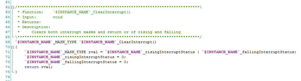
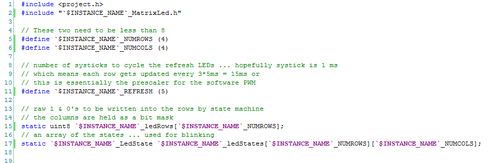
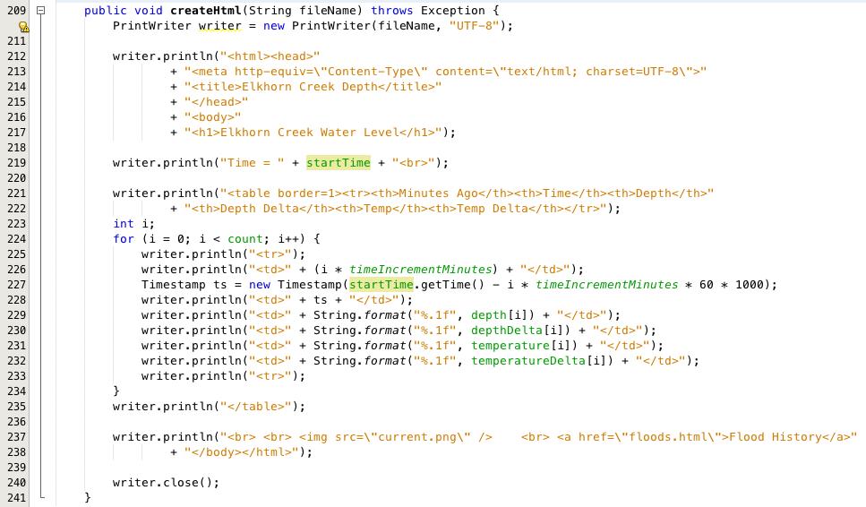
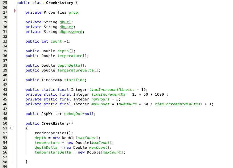
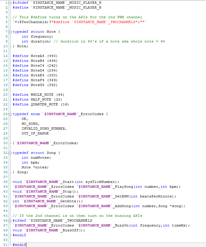
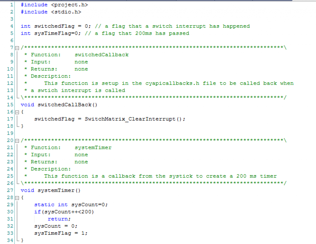
In this previous posts I showed you the Schematic/Symbol and the public API for the Music Player. In this post I will take you through the firmware. The first section defines:
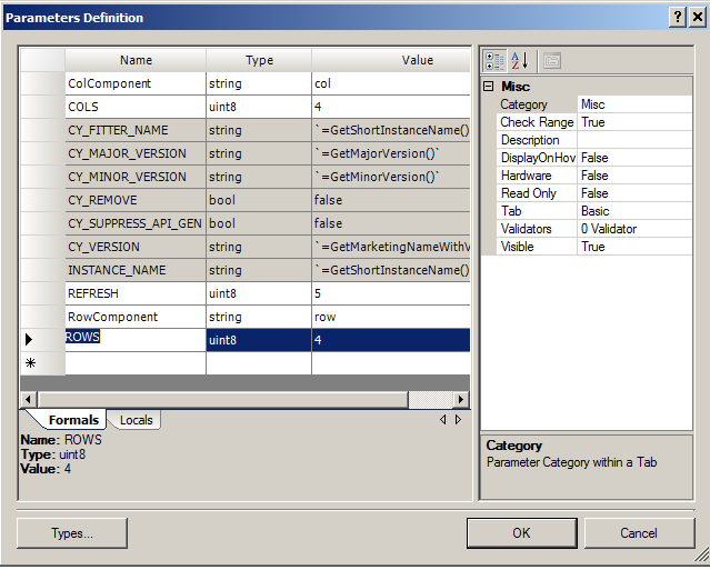
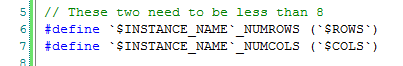
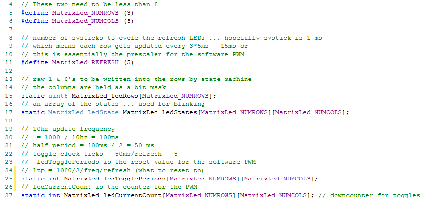
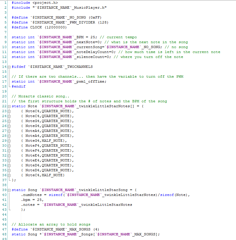
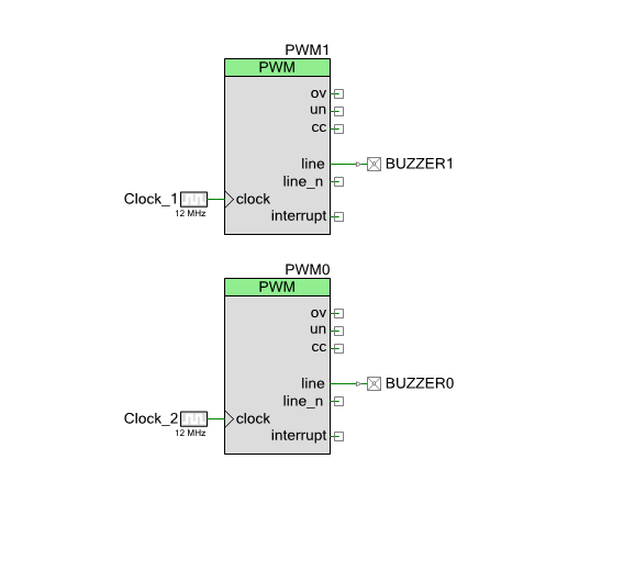
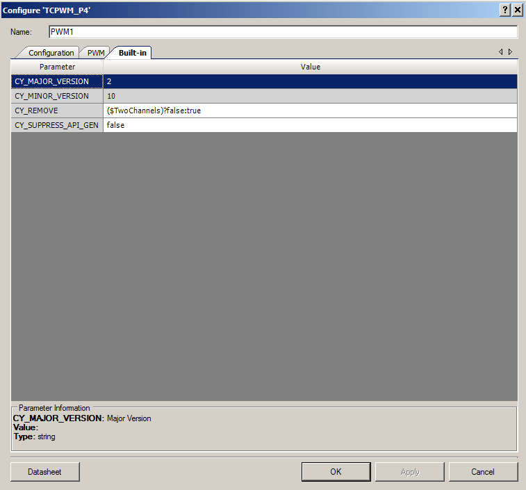
- Parameters of the system, specifically the clock frequency and PWM prescaler (line 4-5)
- The internal variables that are used to keep track with what is happening on the son (lines 8-12).
- The notes for twinkle twinkle little star (Lines 22-43)
- An array to hold songs (line 47-48)
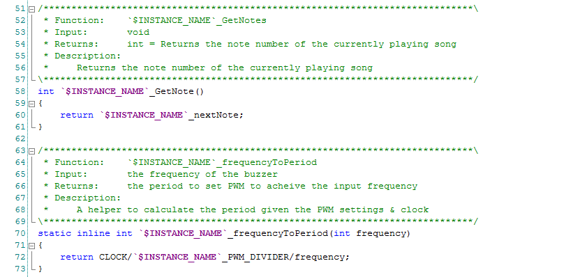
The GetNote function just returns the current songs currently playing note number. I used this function when I was trying to debug the player.
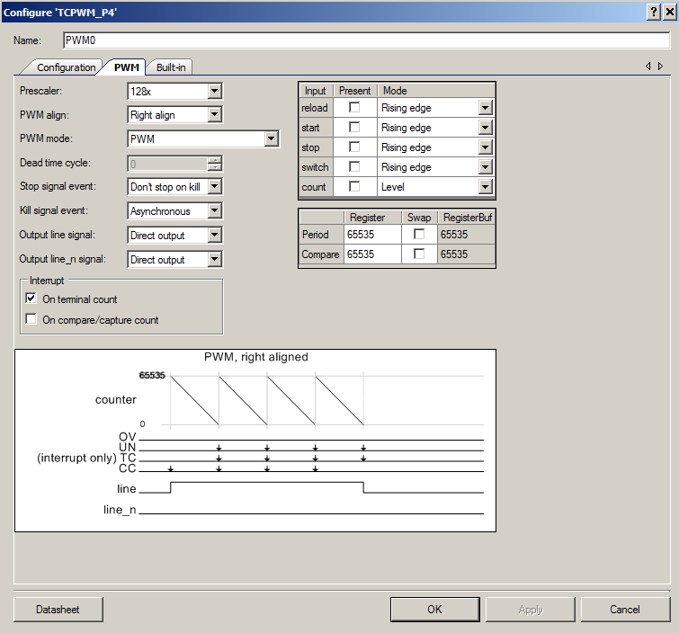
The FrequencyToPeriod uses the settings of the PWM and the desired frequency to calculate the Period/Compare values to achieve the desired output. The PWM has three parameters that change its output.
- The input clock
- The input prescaler (just a divider on the front end of the PWM)
- The period (what you are trying to calculate)
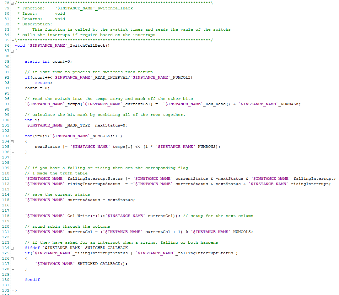
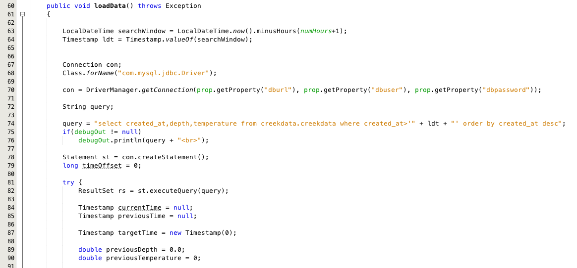
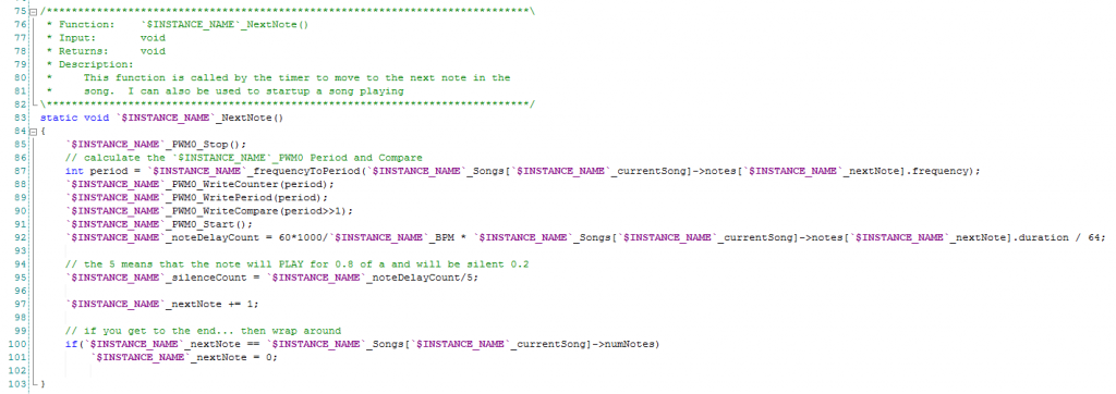
The next note function figures out the right settings for the PWM based on the desired frequency of the note, then sets up the PWM to the correct values (line 88-91), it then calculates how long to play the note (line 92). Finally it sets thing up for the next note (line 97-101)
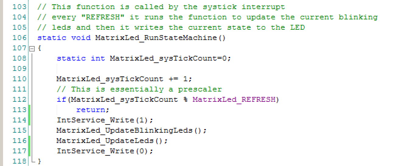
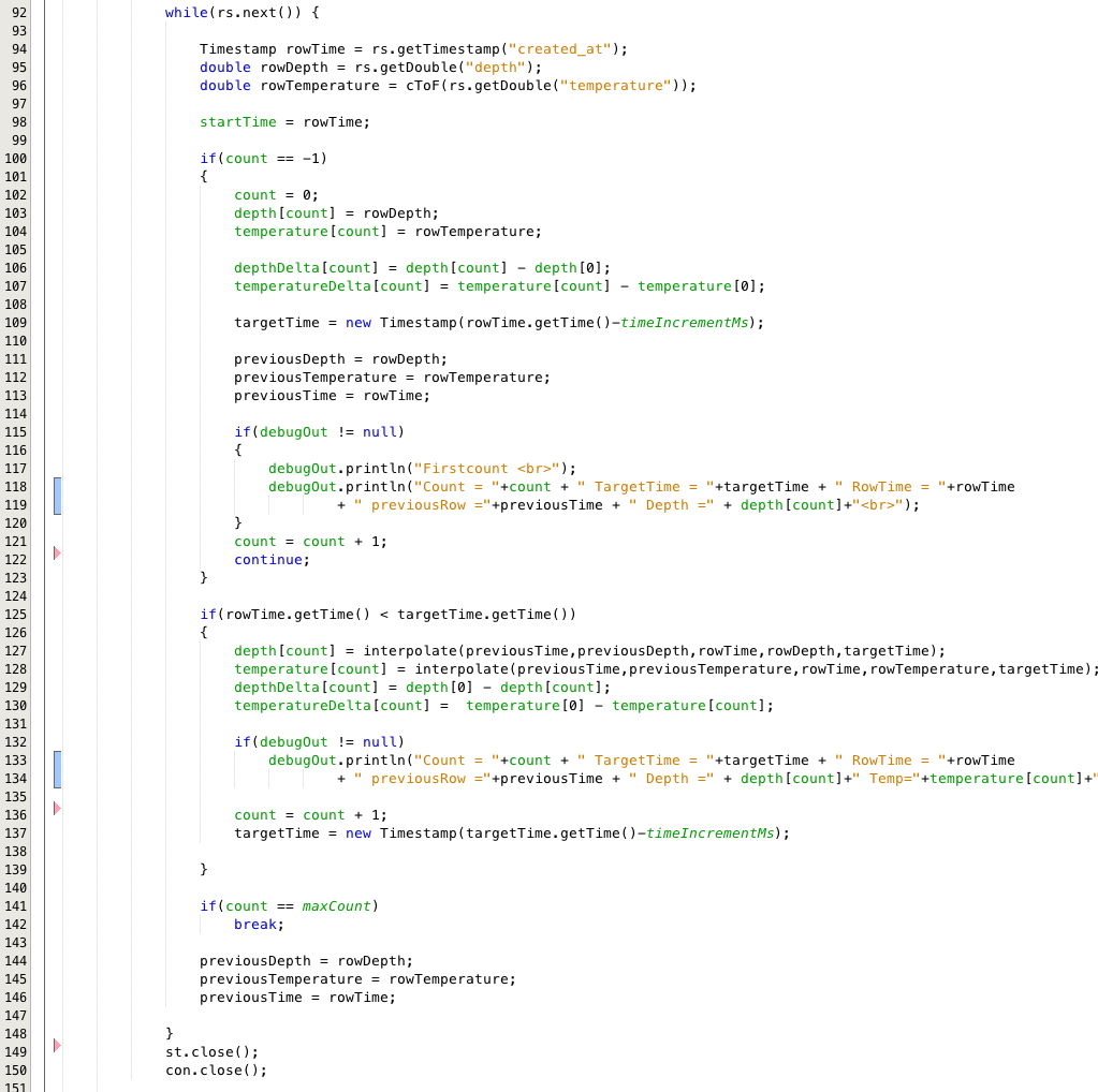
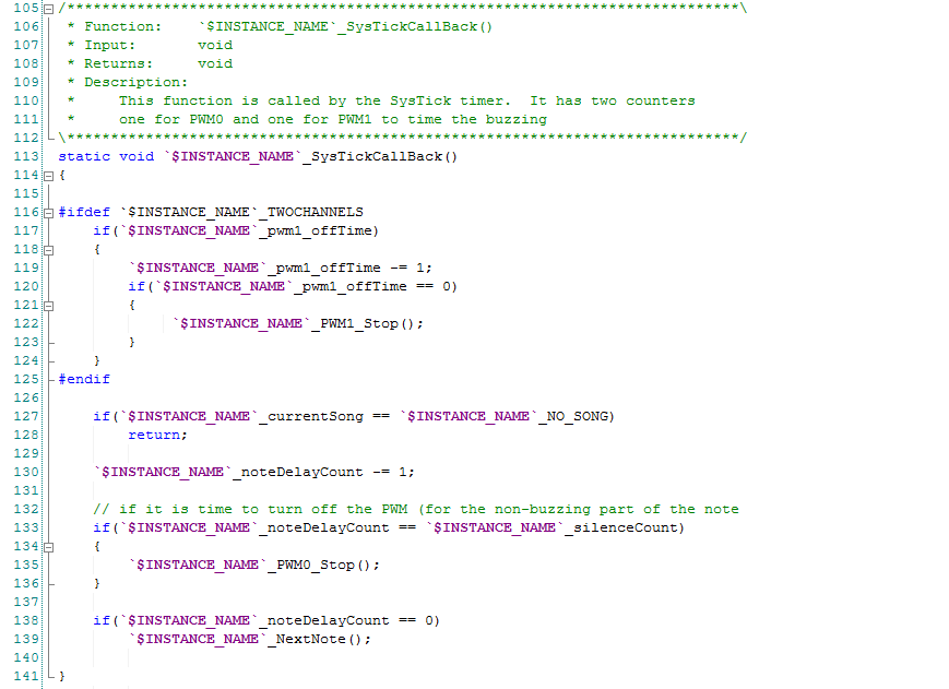
The SysTickCallBack function controls the amount of time that
- A note plays (lines 138-139)
- The gap between the notes (lines 132-136)
- The buzzer sounds (116-124) if the TWO_CHANNELS are enabled
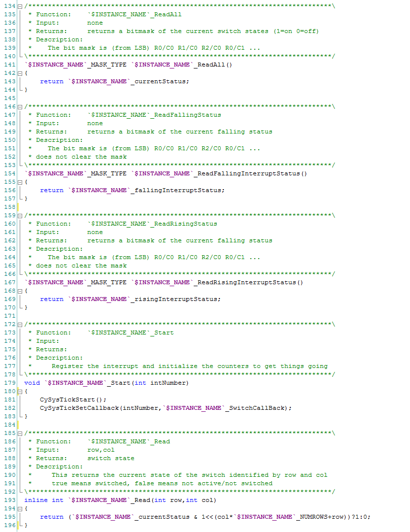
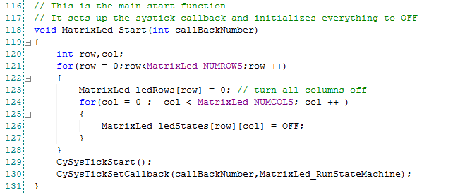
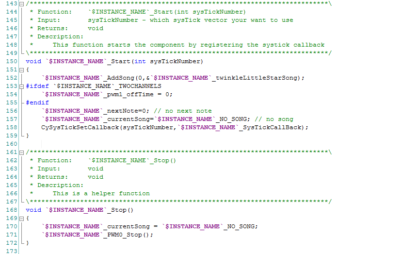
The Start function initializes all of the internal variables to turn off the songs. The MusicPlayer uses the SysTick timer to keep track of how long the notes and the Buzzer have been on/off.
The Stop function turns off the Buzzers.
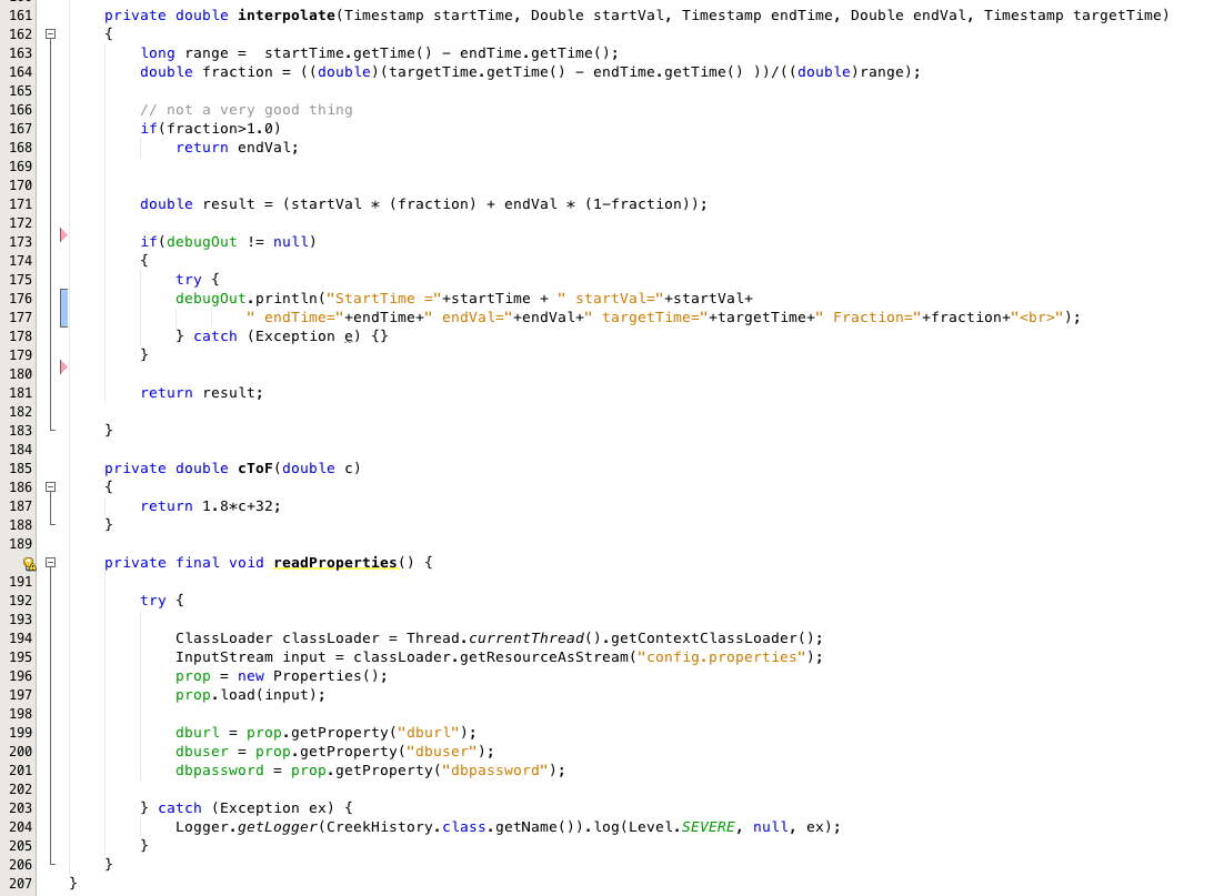
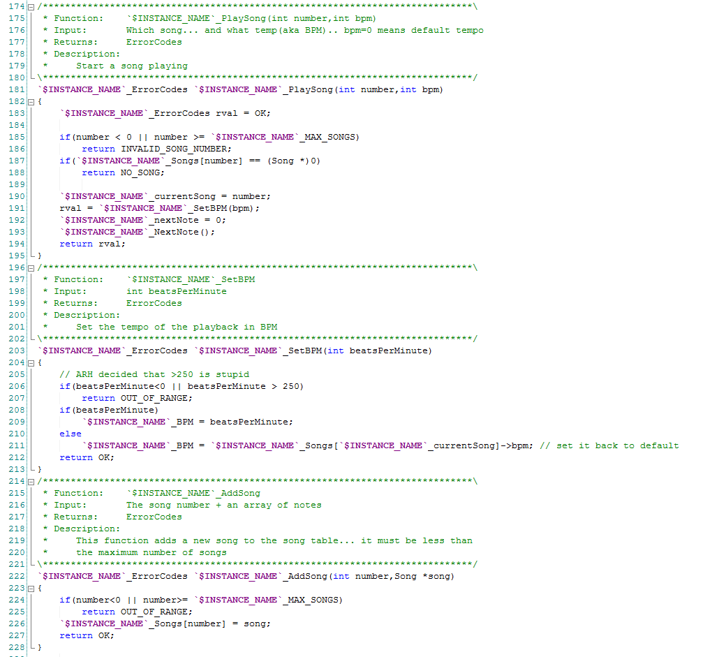
The function PlaySong initializes all of the internal variables that are used to keep track of the song status. It points at the first note, then it calls the NextNote function. This function returns the ErrorCodes value which enables me to do a range check and existence check on the song number (lines 185-188).
The SetBPM changes the internal variable _BPM which is used to calculate the duration of notes. This function also returns an ErrorCodes value after doing a range check.
The AddSong function allows the component user to define a new song and to assign it the list of Songs.
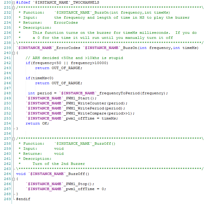
The last section of code provides the buzzing functionality. These function turn on and off the 2nd buzzer. The first function turns on the 2nd buzzer at the requested frequency for either 0-means infinite time or a # of milliseconds. Notice that this section of code only shows up if the user has turned on the second channel (line 230).
In the next post Ill show you the test code for the component.
You can find all of the source code and files at the IOTEXPERT site on github.
Index
Description
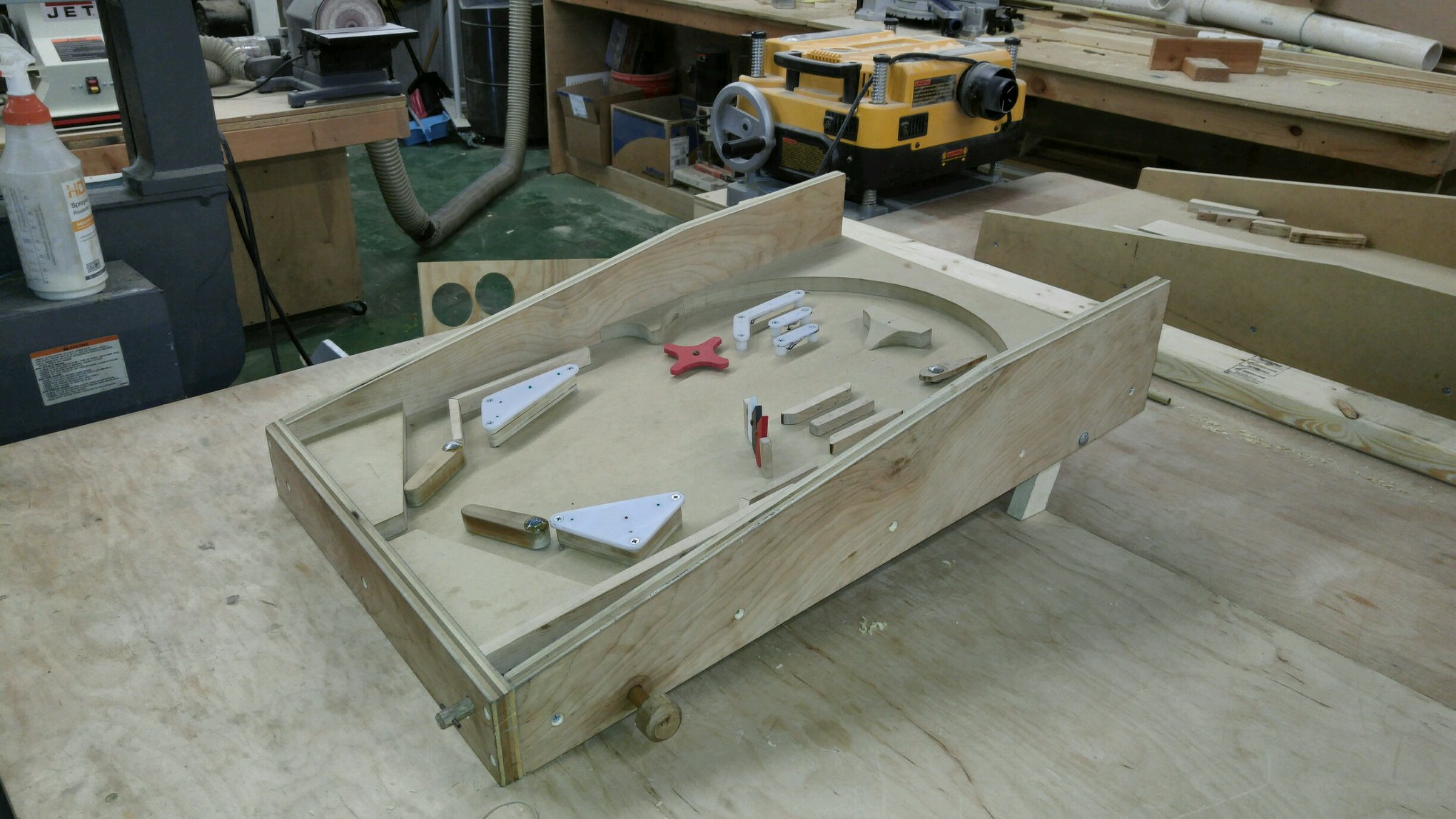
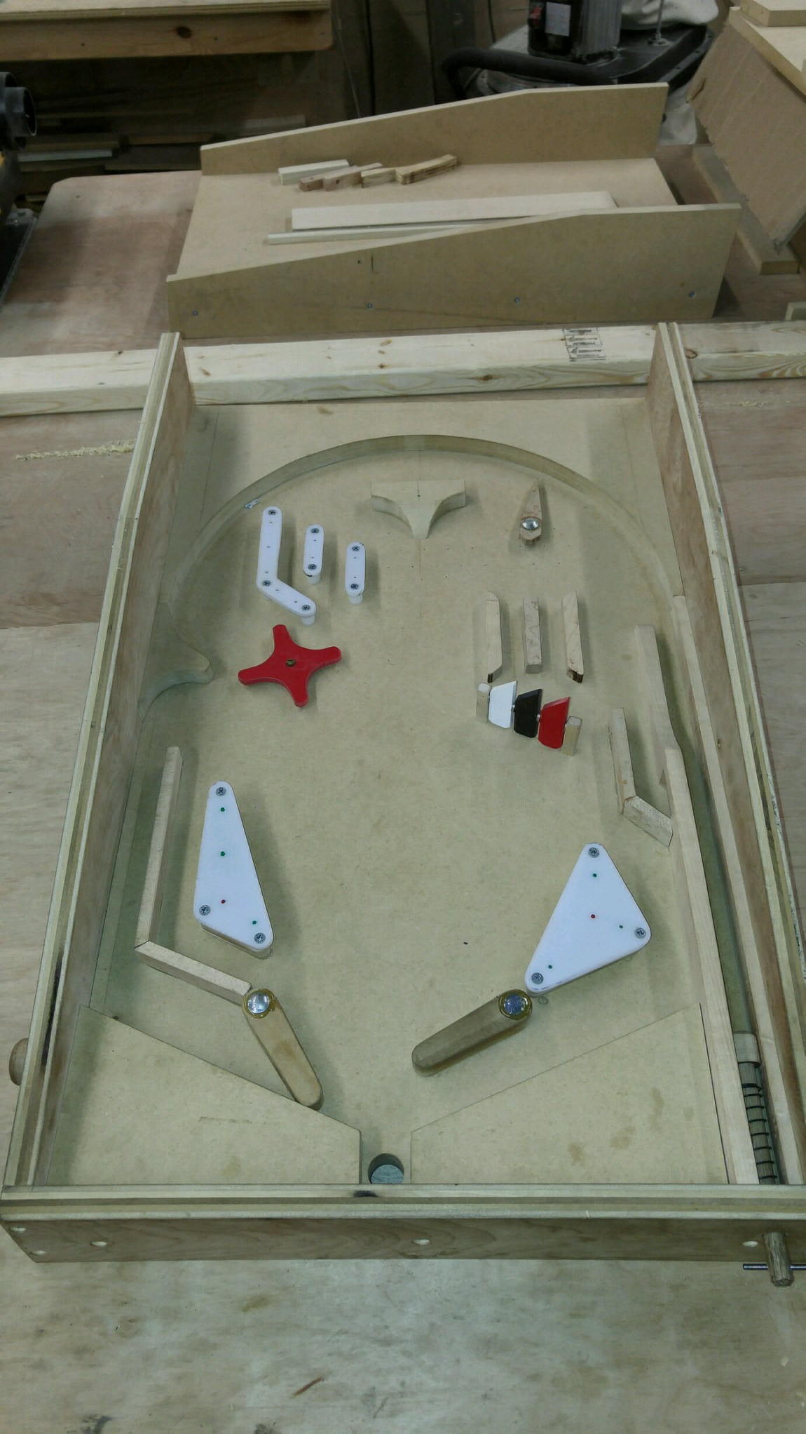
Pinball: Newton's Attic Pinball
An introduction to the project and the goals
Pinball: Lotsa Blinking LEDs
Everyone needs a bunch of LEDs on their Pinball Machine
Pinball: Matrix LEDs (Part 1)
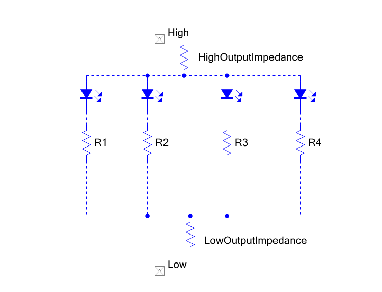
Saving PSoC pins by using a matrix scheme
Pinball: Matrix LEDs (Part 2)
Solving some problems with the matrix
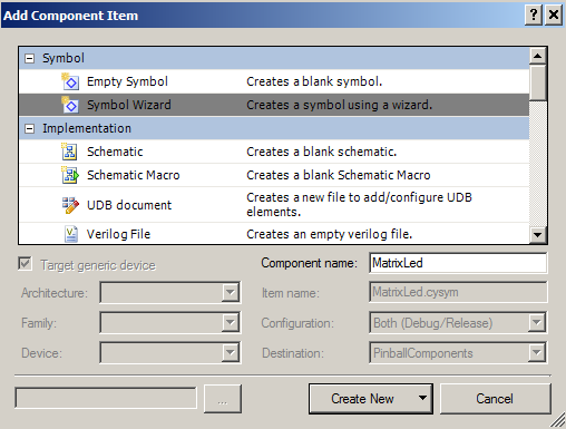
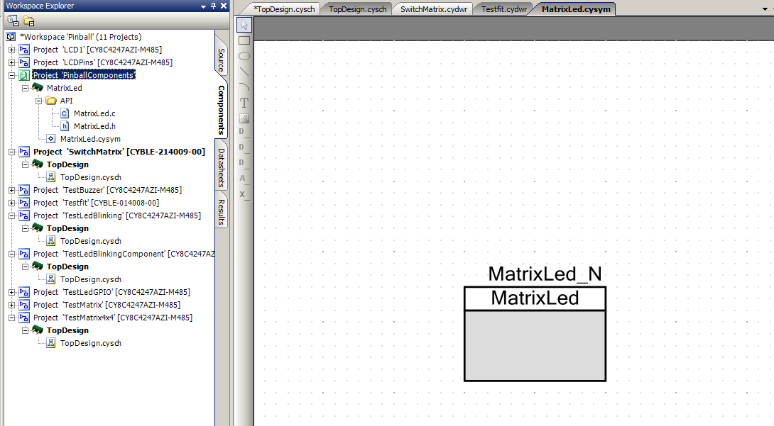
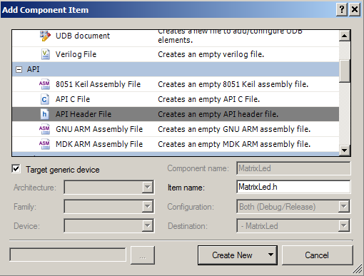
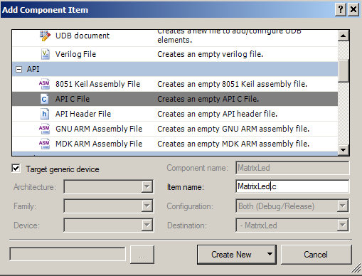
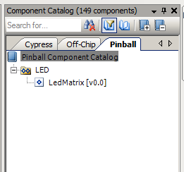
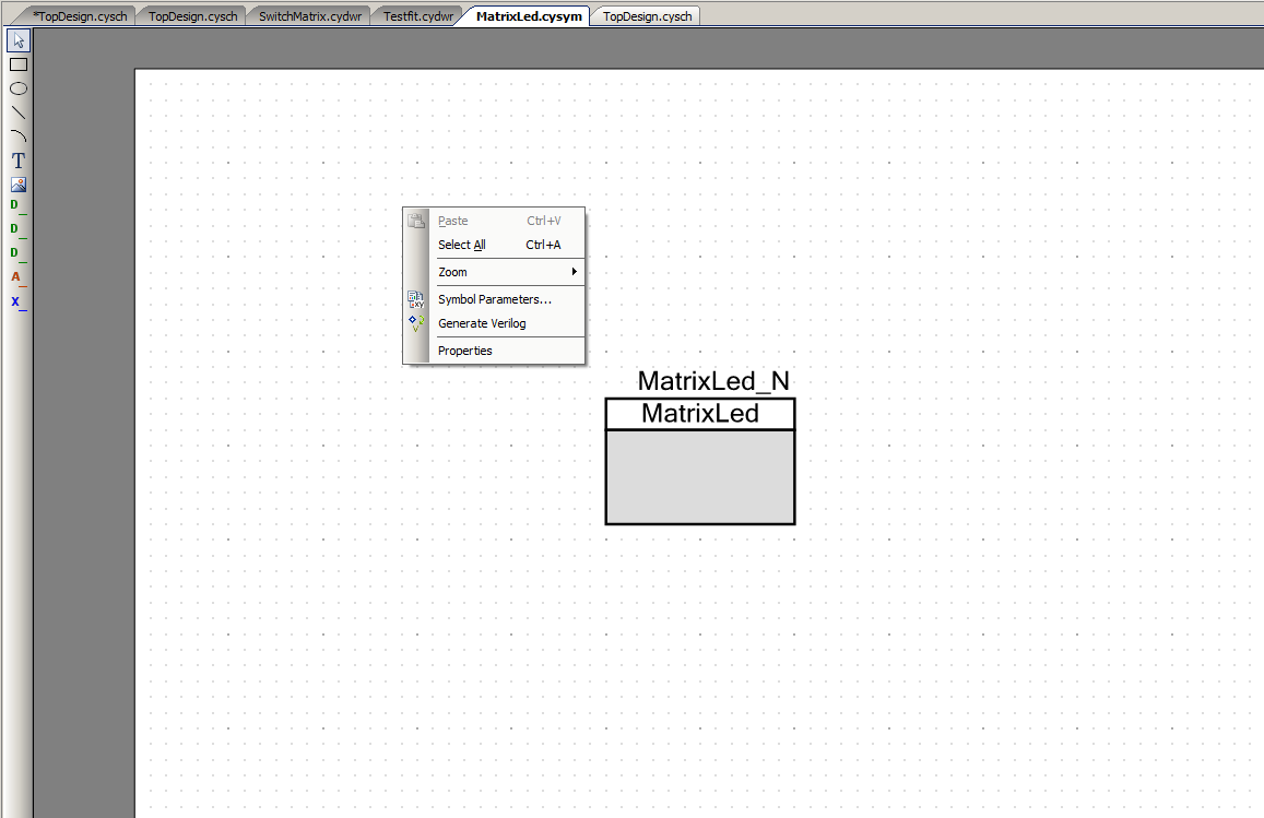
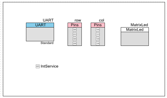
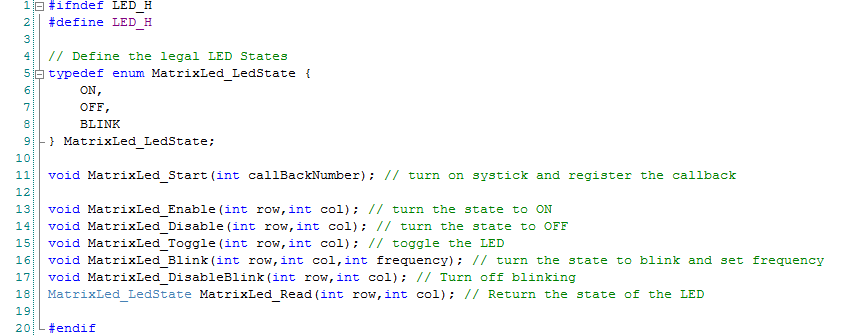
Pinball: Matrix LEDs Component
How to turn the Matrix LED into a component
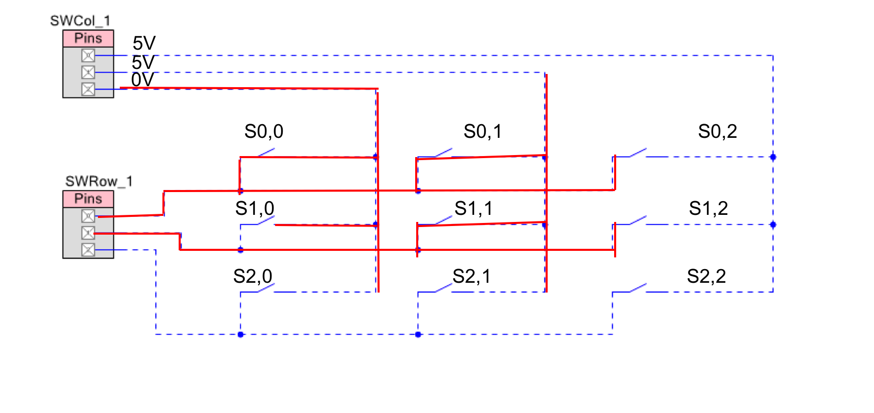
Pinball: A Switch Matrix
Implementing a bunch of switches
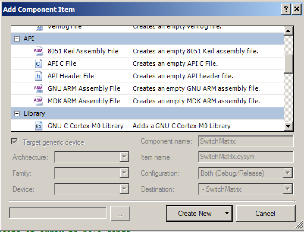
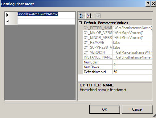
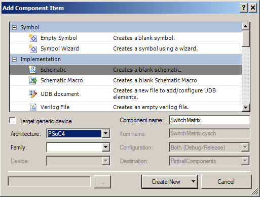
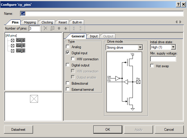
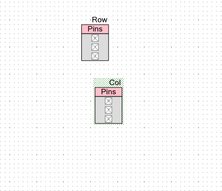
Pinball: Switch Matrix Component (Part 1)
The switch matrix component implementation
Pinball: Switch Matrix Component (Part 2)
The firmware for matrix component
Pinball: Switch Matrix Component (Part 3)
Test firmware for the matrix component
Pinball: The Music Player (Part 1)
The schematic and symbol for a Music Player component
Pinball: The Music Player (Part 2)
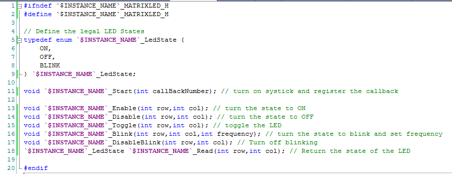
The Public API for the Music Player component
Pinball: The Music Player (Part 3)
The firmware to make the sweet sweet music
Pinball: The Music Player (Part 4)
The test program for the music player
Pinball: The Motors + HBridge
Using an Bridge to control DC Motors
Pinball: The Eagle Schematic
All of the circuits into an Eagle schematic
Pinball: The Printed Circuit Board 1.0
The first Eagle PCB layout of the printed circuit board
Pinball: The PCB Version 1.0 Fail
Problems with the first version of the Eagle PCB layout
Pinball: PCB Layout 1.2 Updates using Eagle
Fixing the errors on the first two versions of the Eagle PCB
Pinball: Assemble and Reflow the 1.2 PCB
Assembling the Eagle PCB
Pinball: Testing the Eagle PCB
Firmware to test the newly built Pinball printed circuit board
Pinball: Debugging the Motor Driver
Fixing the motor driver PSoC project
Pinball: Hot-Air Reworking the Accelerometer Solder
Using a Hot-Air Rework tool to reflow a QFN
Pinball: Debugging the LM317 Power Supply- A Tale of Getting Lucky
Debugging the LM317/LM117 power supply
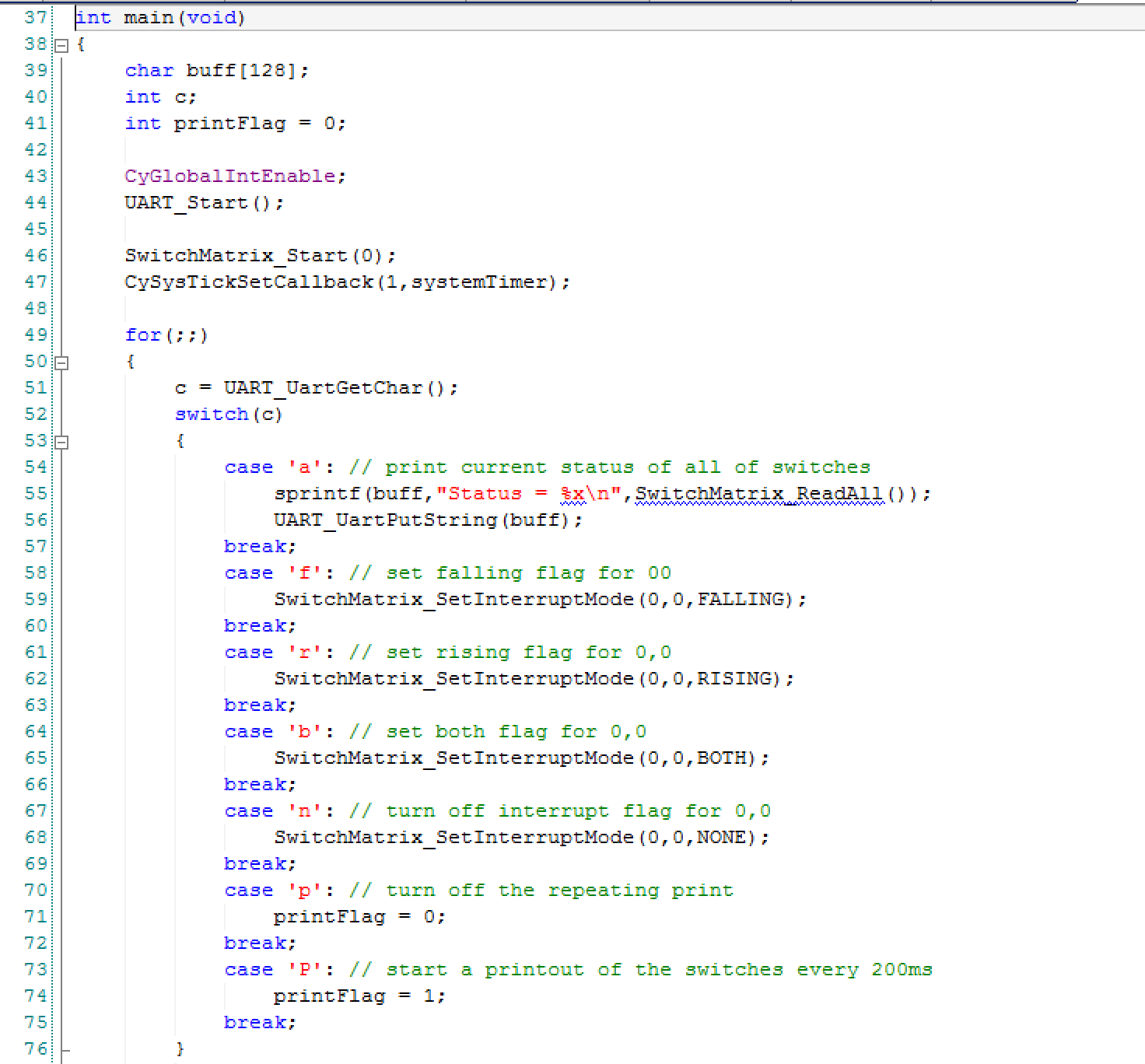
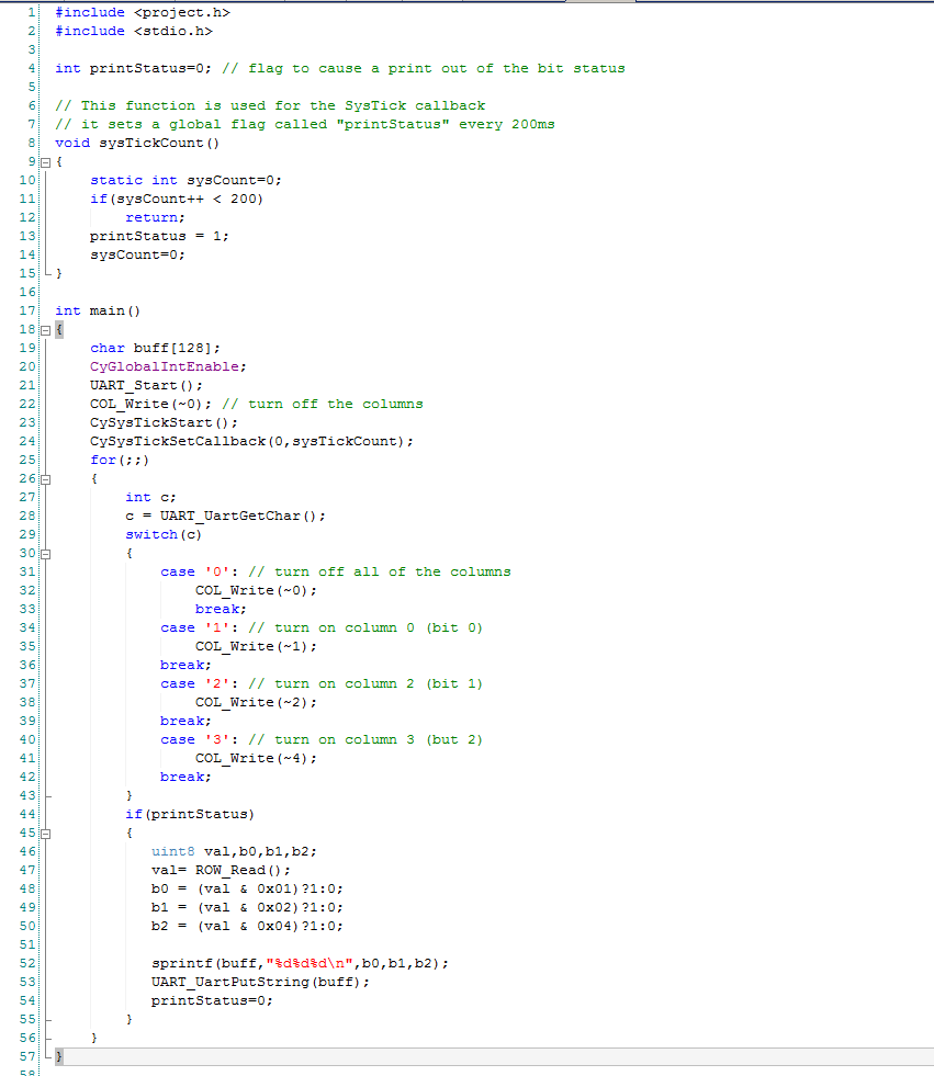
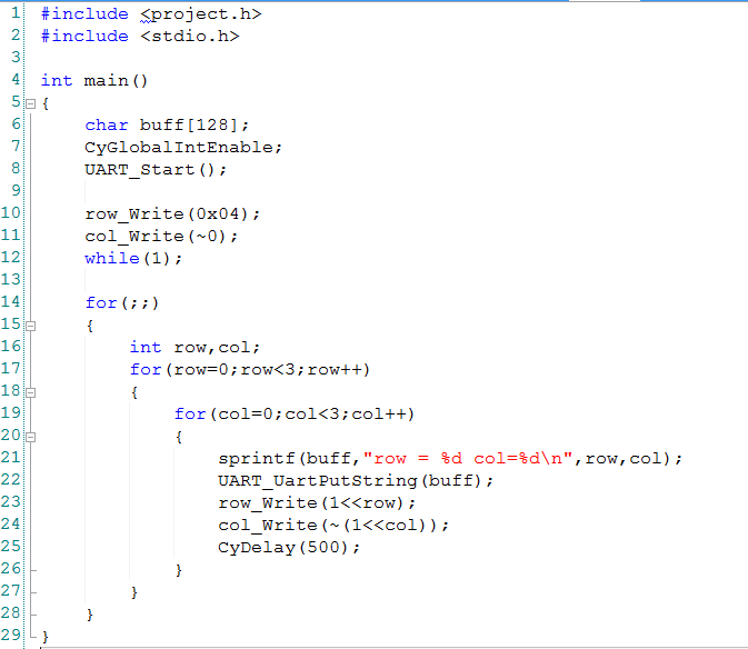
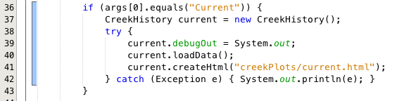
 In the main program I first start all of the components, interrupts etc in lines 43-47. On lines 52-75 I process the user input and try out different functions of the component.