Summary of FreeRTOS FAT SL FileSystem Port
In the previous article I discussed the Cypress 24V10 FRAM which I am going to use to store nonvolatile data for the FreeRTOS FAT SL FileSystem. The “SL” in the name stands for “super light” and was built by HCC Embedded for, get this, embedded applications.
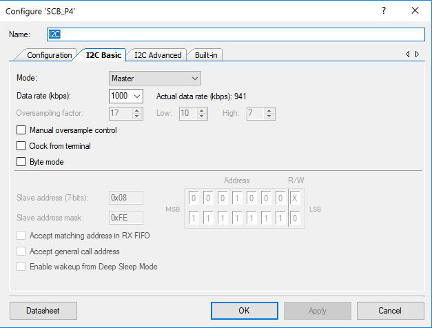
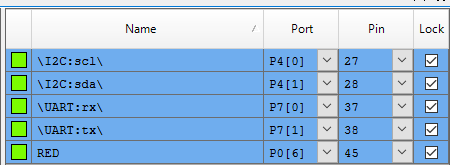
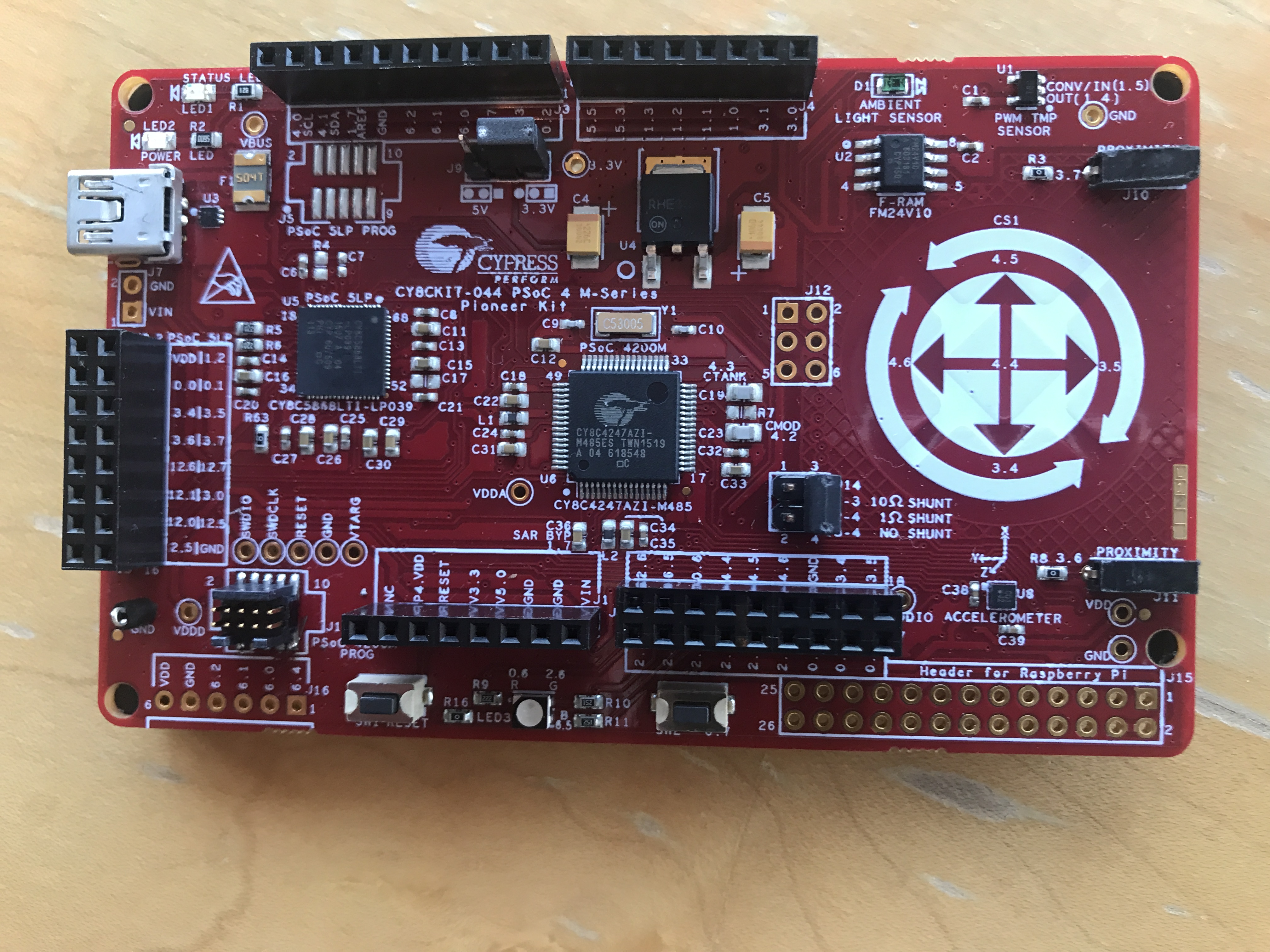
In this article I am going to show you how to build a media driver to make the FreeRTOS FAT SL FileSystem work. In the next article I will talk about how to actually use the FreeRTOS FAT SL FileSystem on the CY8CKIT-044 using the Cypress FMV24V10 FRAM.
The media driver is pretty simple, you just need to provide the following functions:
And two structures
- F_DRIVER – Function pointers to the media driver functions
- F_PHY – Information about the FRAM
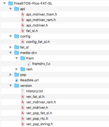
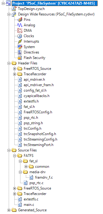
To make all of this work I will start by copying the “ram” driver that was provided as an example (ill call mine framdrv_f.c). The file that I started with resides in FreeRTOS-Plus/Source/FreeRTOS-Plus-FAT-SL/media-drv/ram/ramdrv_f.c
F_DRIVER Structure
The F_DRIVER structure mostly contains function pointers to the driver functions (which you create). All throughout the FreeRTOS FAT SL FileSystem code it will do things like :
status = mdrv->getstatus( mdrv );
which calls the function in the media driver structure named “getstatus”.
Here is the exact definition of the F_DRIVER STRUCTURE (found in FreeRTOS-Plus-FAT-SL/api/api_mdriver.h) :
typedef struct F_DRIVER F_DRIVER;
typedef int ( *F_WRITESECTOR )( F_DRIVER * driver, void * data, unsigned long sector );
typedef int ( *F_READSECTOR )( F_DRIVER * driver, void * data, unsigned long sector );
typedef int ( *F_GETPHY )( F_DRIVER * driver, F_PHY * phy );
typedef long ( *F_GETSTATUS )( F_DRIVER * driver );
typedef void ( *F_RELEASE )( F_DRIVER * driver );
typedef struct F_DRIVER
{
unsigned long user_data; /* user defined data */
void * user_ptr; /* user define pointer */
/* driver functions */
F_WRITESECTOR writesector;
F_READSECTOR readsector;
F_GETPHY getphy;
F_GETSTATUS getstatus;
F_RELEASE release;
} _F_DRIVER;
typedef F_DRIVER *( *F_DRIVERINIT )( unsigned long driver_param );
The user_data and user_ptr do not appear to be used anywhere in the FreeRTOS FAT SL FileSystem code, so I am not sure what they had in mind for those variables.
The F_PHY Structure
The other structure that is needed (sort of) is F_PHY. This structure contains parameters that were originally meant for disk drives and are no longer used. For the FRAM I will divide up the 128k array into “sectors” of “512” bytes. For some reason which I don’t understand the sector size must be fixed to 512 bytes. The history of FAT filesystems is incredibly messy, and I started to dig through it so that I understood the number, but I am not sure that there are enough hours in my life.
typedef struct
{
unsigned short number_of_cylinders;
unsigned short sector_per_track;
unsigned short number_of_heads;
unsigned long number_of_sectors;
unsigned char media_descriptor;
unsigned short bytes_per_sector;
} F_PHY;
As I wrote this article I didnt remember setting up the F_PHY structure… but things still worked (ill address this later in the article).
F_DRVERINIT()
This function sets up the function pointers and marks the in_use variable.
/****************************************************************************
*
* fram_initfunc
*
* this init function has to be passed for highlevel to initiate the
* driver functions
*
* INPUTS
*
* driver_param - driver parameter
*
* RETURNS
*
* driver structure pointer
*
***************************************************************************/
F_DRIVER * fram_initfunc ( unsigned long driver_param )
{
( void ) driver_param;
UART_UartPutString("Calling init\n");
if( in_use )
return NULL;
(void)psp_memset( &t_driver, 0, sizeof( F_DRIVER ) );
t_driver.readsector = fram_readsector;
t_driver.writesector = fram_writesector;
t_driver.getphy = fram_getphy;
t_driver.release = fram_release;
in_use = 1;
return &t_driver;
} /* fram_initfunc */
F_GETPHY()
This function returns information about the FRAM including the size (in sectors) and the size of the sectors (in bytes)
/****************************************************************************
*
* ram_getphy
*
* determinate ramdrive physicals
*
* INPUTS
*
* driver - driver structure
* phy - this structure has to be filled with physical information
*
* RETURNS
*
* error code or zero if successful
*
***************************************************************************/
static int fram_getphy ( F_DRIVER * driver, F_PHY * phy )
{
/* Not used. */
( void ) driver;
phy->number_of_sectors = maxsector;
phy->bytes_per_sector = F_SECTOR_SIZE;
return MDRIVER_RAM_NO_ERROR;
}
FRAM Helper Functions
In order to map sectors to the correct I2C address (remember the FRAM has two banks of memory in two different I2C addresses) and to the correct bank address, I created two function which map “sector” into address and I2C address.
static const unsigned long maxsector = FDRIVER_VOLUME0_SIZE / F_SECTOR_SIZE;
static const unsigned long halfsector = FDRIVER_VOLUME0_SIZE / F_SECTOR_SIZE / 2;
/****************************************************************************
*
* calcAddress
*
* This function takes a sector and returns the address in the bank for the
* start of the secor
*
* INPUTS
*
* unsigned long sector - which logical sector in the FRAM
*
* RETURNS
*
* The FRAM Address of the sector
*
***************************************************************************/
static inline uint32_t calcAddress(unsigned long sector)
{
if(sector < halfsector)
return sector * F_SECTOR_SIZE;
else
return (sector-halfsector) * F_SECTOR_SIZE;
}
/****************************************************************************
*
* calcI2CAddress
*
* This function takes a sector from 0 --> maxsector and figures out which bank
* the address exists.
*
* INPUTS
*
* unsigned long sector - which logical sector in the FRAM to write to
*
* RETURNS
*
* The I2C Address of Bank 0 or Bank 1
*
***************************************************************************/
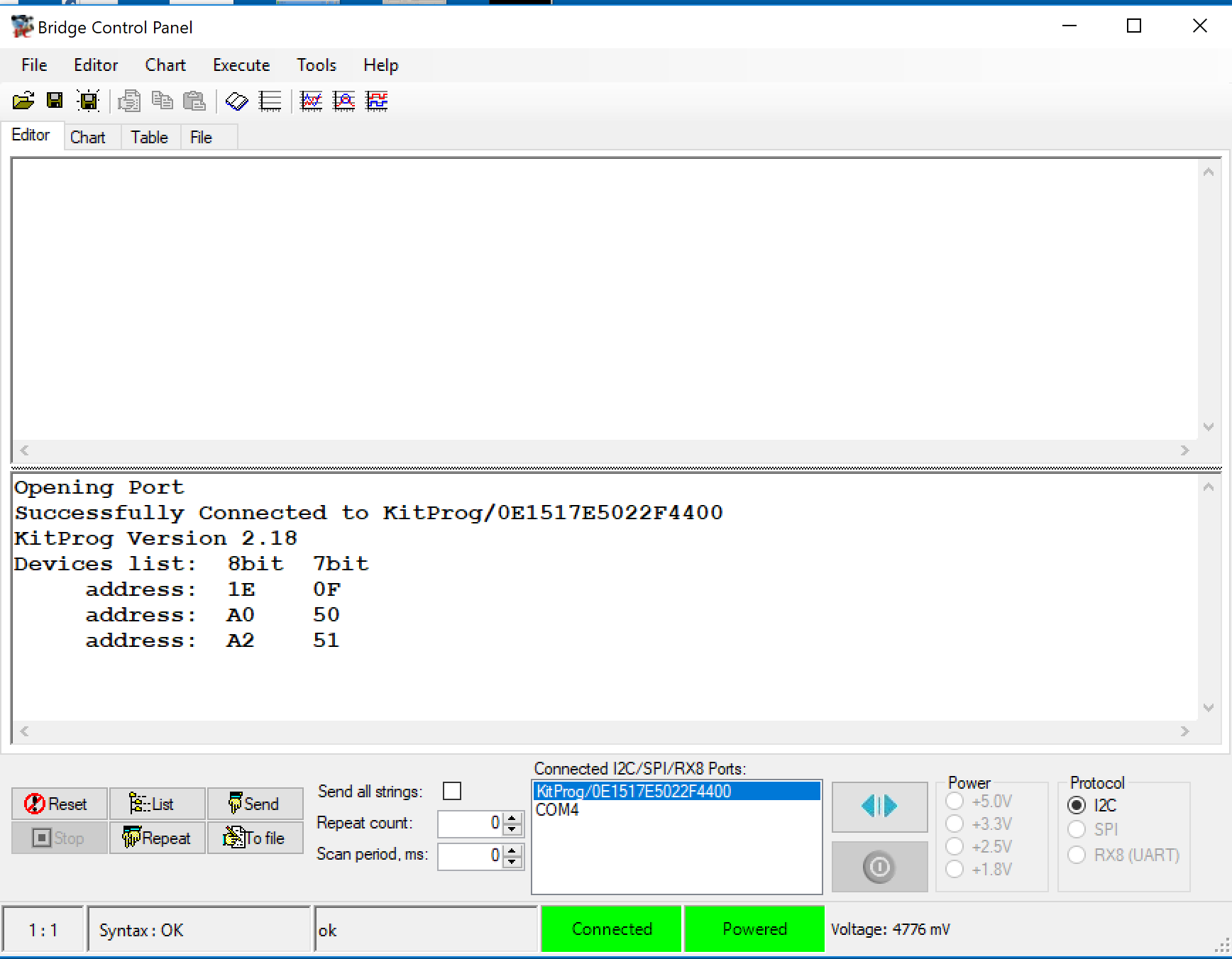
static inline uint32_t calcI2CAddress(unsigned long sector)
{
if(sector < halfsector)
return 0x50; // I2C Bank 0 Address from the datasheet
else
return 0x51; // I2C Bank 0 Address - From the datasheet
}
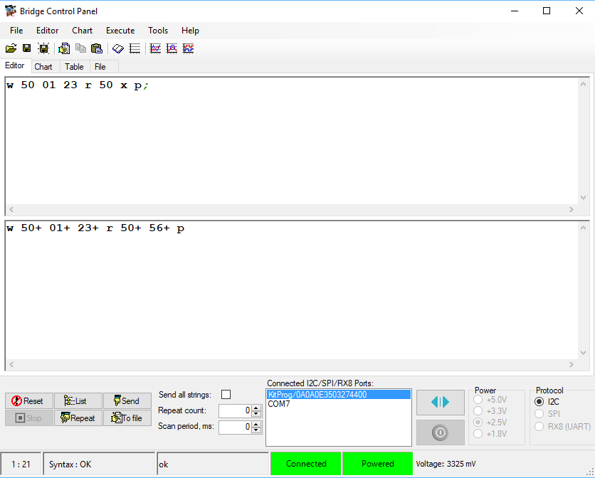
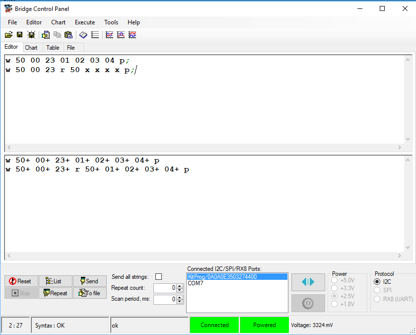
F_READSECTOR()
This function reads 512 bytes that are located in the sector into the RAM buffer pointed to by data. Notice on lines 26 & 27 I put in debugging information. In order to read you need to
- Send a start (line 30)
- Send the I2C address and the write bit
- Set the address you want to read from (line 37-38)
- Send a restart (line 41)
- read the 512 bytes (lines 44-54)
- On the last byte NAK (line 47-50)
/****************************************************************************
*
* fram_readsector
*
* This function reads 512 bytes into the SRAM at the pointer data
*
* INPUTS
*
* driver - driver structure
* void *data - a pointer to the SRAM where the 512 bytes of data will be written
* unsigned long sector - which logical sector in the FRAM to read from
*
* RETURNS
*
* error code or MDRIVER_RAM_NO_ERROR if successful
*
***************************************************************************/
static int fram_readsector ( F_DRIVER * driver, void * data, unsigned long sector )
{
char buff[128]; // A scratch buffer for UART Printing
(void)driver;
uint16 address;
uint32_t status;
sprintf(buff,"Read sector %d\n",(int)sector);
UART_UartPutString(buff);
address = calcAddress(sector);
  status = I2C_I2CMasterSendStart( calcI2CAddress(sector),I2C_I2C_WRITE_XFER_MODE);
    if(status != I2C_I2C_MSTR_NO_ERROR)
    {
        UART_UartPutString("I2C Error\n");
        return MDRIVER_RAM_ERR_SECTOR;
    }
    int i;
    I2C_I2CMasterWriteByte((address>>8)&0xFF);
    I2C_I2CMasterWriteByte(address & 0xFF); //
I2C_I2CMasterSendRestart(calcI2CAddress(sector),I2C_I2C_READ_XFER_MODE);
uint8_t d;
for(i=0;i<F_SECTOR_SIZE;i++)
{
if(i != F_SECTOR_SIZE - 1)
d = I2C_I2CMasterReadByte(I2C_I2C_ACK_DATA);
else
d = I2C_I2CMasterReadByte(I2C_I2C_NAK_DATA);
*((uint8_t *)data + i) = d;
}
I2C_I2CMasterSendStop();
return MDRIVER_RAM_NO_ERROR;
}
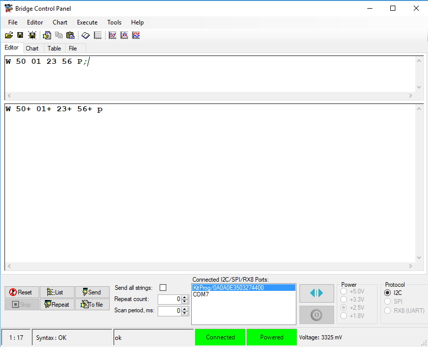
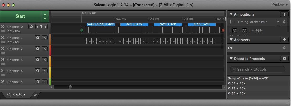
F_WRITESECTOR()
The write sector is very similar to the read. To write the data you need to
- Send a start (line 204)
- Write the address you want to write to (line 205-206)
- Write the 512 bytes (lines 208-214)
- Send a stop (line 215)
/****************************************************************************
 *
 * fram_writesector
 *
 * This function takes 512 bytes of user input and writes to the FRAM in the
 *
 * INPUTS
 *
 * driver - driver structure
 * void *data - a pointer to the SRAM where the 512 bytes of data exists
 * unsigned long sector - which logical sector in the FRAM to write to
 *
 * RETURNS
 *
 * error code or MDRIVER_RAM_NO_ERROR if successful
 *
 ***************************************************************************/

static int fram_writesector ( F_DRIVER * driver, void * data, unsigned long sector )
{
    (void)driver;
    char buff[128]; // A scratch buffer for UART Printing
    uint16 address;
    int i;

    sprintf(buff,"Wrote sector %d\n",(int)sector);
    UART_UartPutString(buff);

    address = calcAddress(sector);
    I2C_I2CMasterSendStart(calcI2CAddress(sector),I2C_I2C_WRITE_XFER_MODE);
    I2C_I2CMasterWriteByte((address>>8)&0xFF);
    I2C_I2CMasterWriteByte(address & 0xFF); //

    for(i=0;i<F_SECTOR_SIZE;i++)
    {
        uint8_t d = *((uint8_t *)data +i);

        I2C_I2CMasterWriteByte(d);

    }
    I2C_I2CMasterSendStop();

  return MDRIVER_RAM_NO_ERROR;
}
F_GETSTATUS()
As I wrote the article I noticed in the documentation that I needed to provide the “F_GETSTATUS” function. The reason that I had not noticed before was that it was not in the media driver provided in the distribution. That being said, my implementation always returns a 0 indicating OK.
/****************************************************************************
 *
 * fram_getstatus
 *
 * This function must return the status of the drive... F_ST_MISSING, F_ST_CHANGED
 * or F_ST_WRPROECT or 0 (for OK)
 * INPUTS
 *
 * driver_param - driver parameter
 *
 *
 * For the FRAM I dont support any of these other status's
 ***************************************************************************/

static long fram_getstatus(F_DRIVER *driver)
{
    (void) driver;
    // F_ST_MISSING	The media is not present (it has been removed or was never inserted).
    //F_ST_CHANGED	Since F_GETSTATUS() was last called the media has either been removed and re-inserted, or a different media has been inserted.
    //F_ST_WRPROTECT	The media is write protected.

    return 0;
}
F_RELEASE()
This function simply set the in_use to 0;
/****************************************************************************
 *
 * fram_release
 *
 * Releases a drive
 *
 * INPUTS
 *
 * driver_param - driver parameter
 *
 ***************************************************************************/
static void fram_release ( F_DRIVER * driver )
{
  /* Not used. */
  ( void ) driver;

  /* Disk no longer in use. */
  in_use = 0;
}
In the next article I will show you the source code for an example project using the FreeRTOS FAT SL Filesystem.