Pattern Agents are running a crowd funding effort for ThingSoC TSoC4L … help them here
Summary
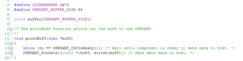
In the previous ThingSoC post I took you through building the firmware to make the PSoC4L drive the ThingSoC I2C hub. Now what? When originally looking around I saw a picture with 4x LCDs connected to the I2C hub, which I thought was cool. In this post Ill show you how to do the same thing with PSoC and the U8G2 library which I talked about in this article. To do this I will:
- Create New PSoC4L Project + Integrate the U8G2 Library
- Update the PSoC4L Firmware
- Test the PSoC4L Firmware
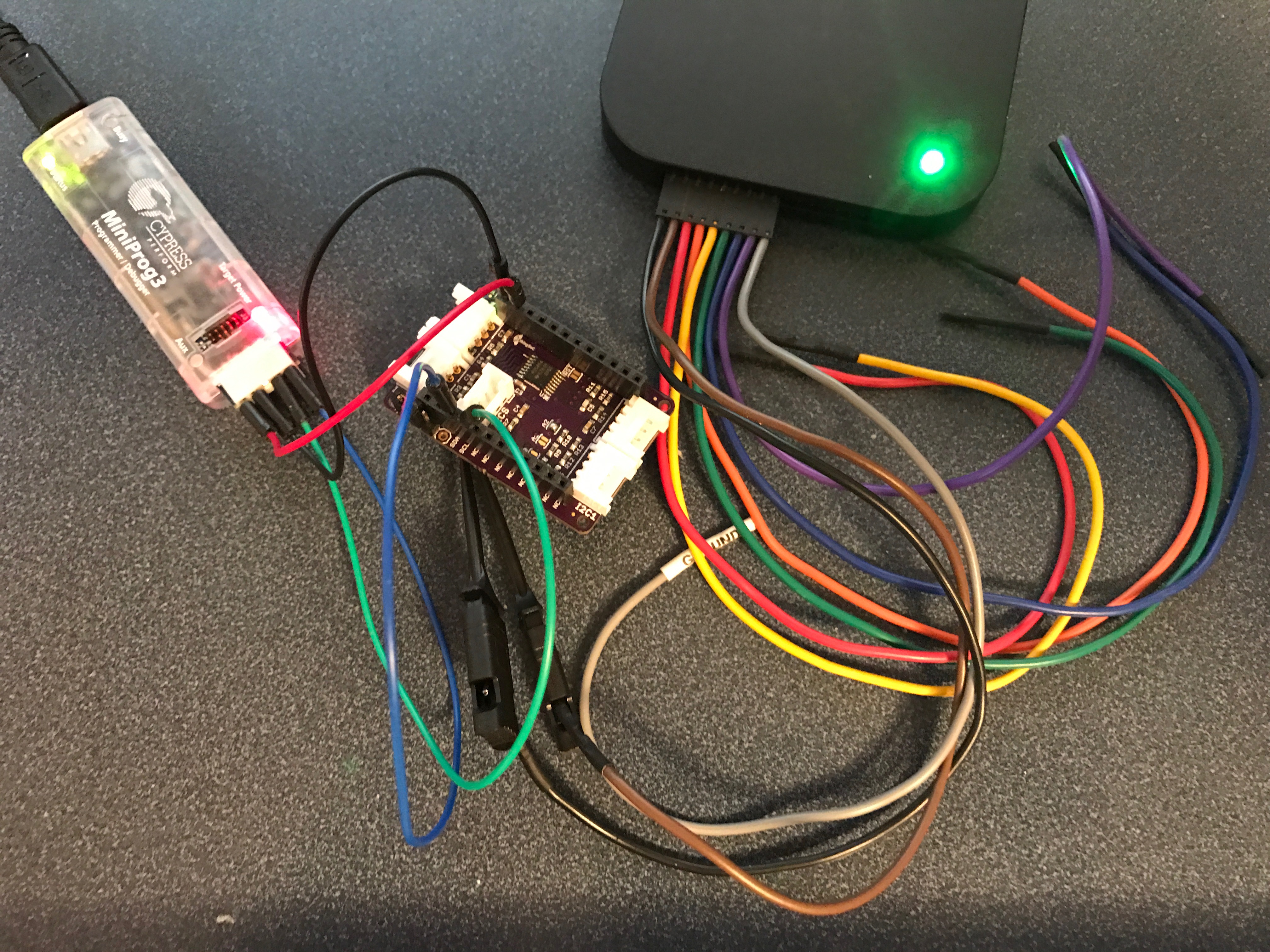
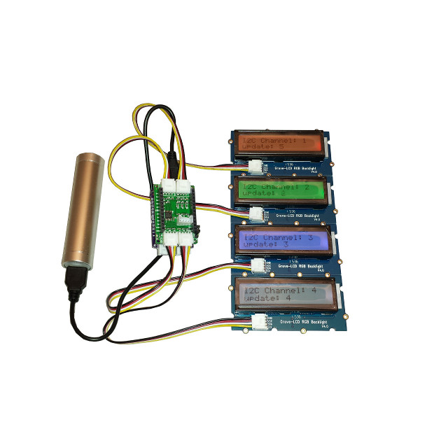
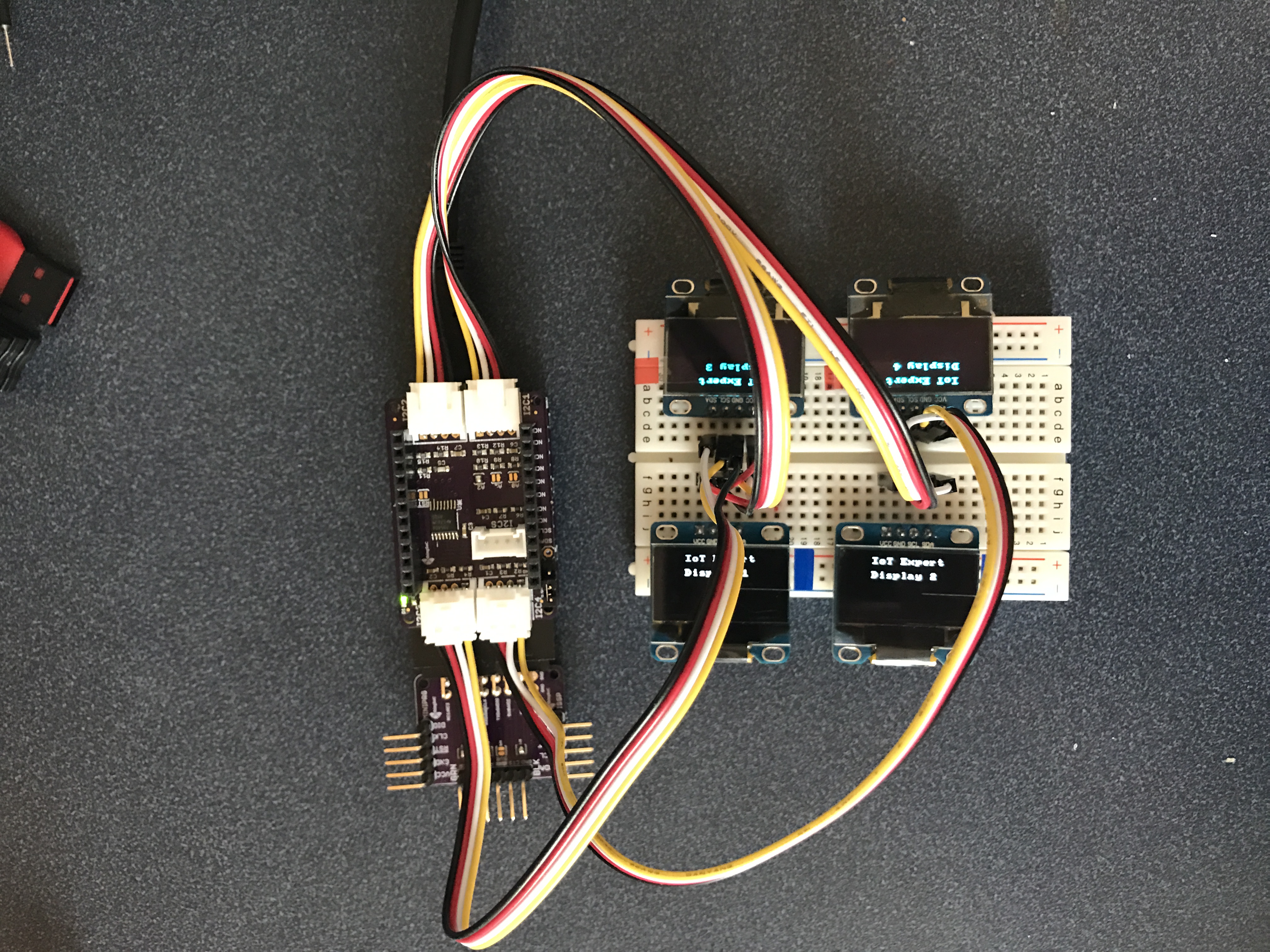
Here is the picture:
Create New PSOC4L Project + Integrate the U8G2 Library
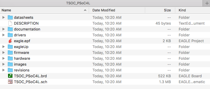
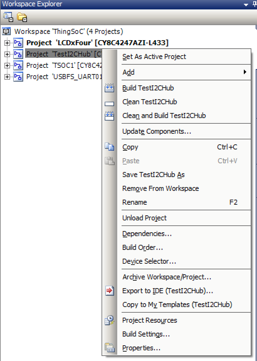
Maybe it should have been obvious, but for some reason it never occurred to me to do a copy/paste to duplicate a project. I guess that I’m slow that way. To do this right click on a project in the workspace explorer and then do paste.
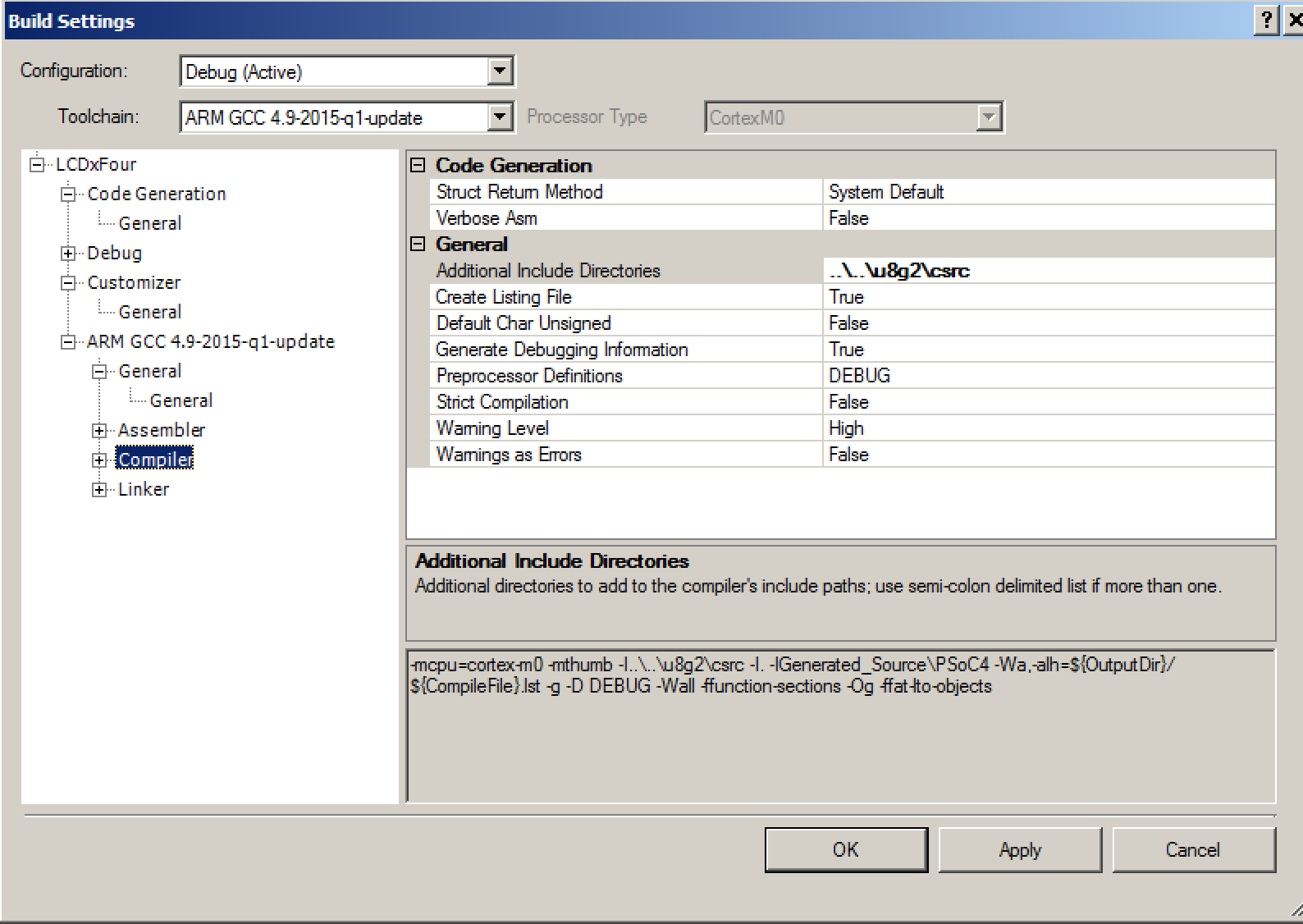
The next step is to integrate the firmware from the U8G2 Library. Start by “gitting” with “git@github.com:olikraus/u8g2.git”. Then you need to add the directory to your project by right clicking the project and selecting “Build Settings”. You need to add U8G2 Library to the additional include directories.
Add the all of the .h and .c files by right clicking the project and selection “Add->Existing Item”
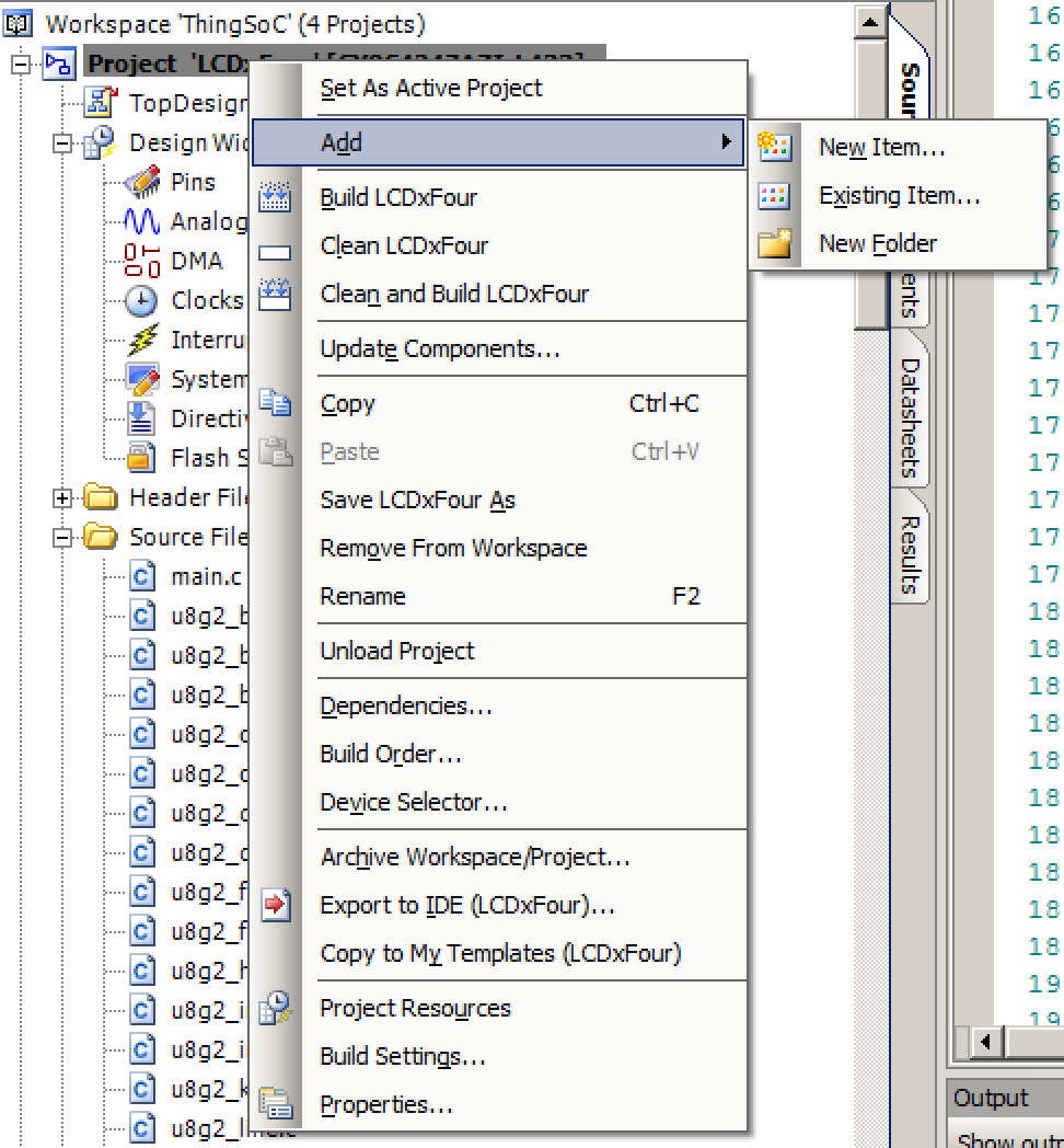
Navigate to the U8G2 library and add all of the .c and .h files. The last thing you need is to bring in the HAL that I wrote for PSoC and described in this post. Specifically you need to bring in the two functions
- psoc_gpio_and_delay_cb
- u8x8_byte_hw_i2c
I suppose that I should package the whole thing up in a component. But, Ill leave that as an exercise for the reader.
Update the PSoC4L Firmware
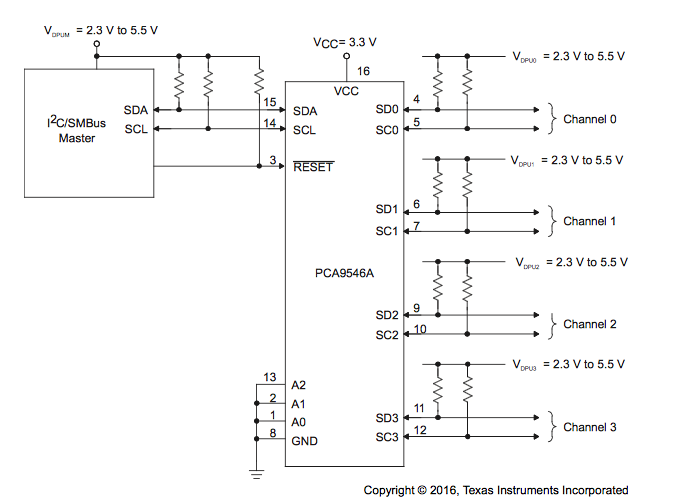
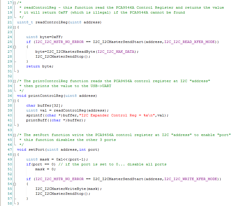
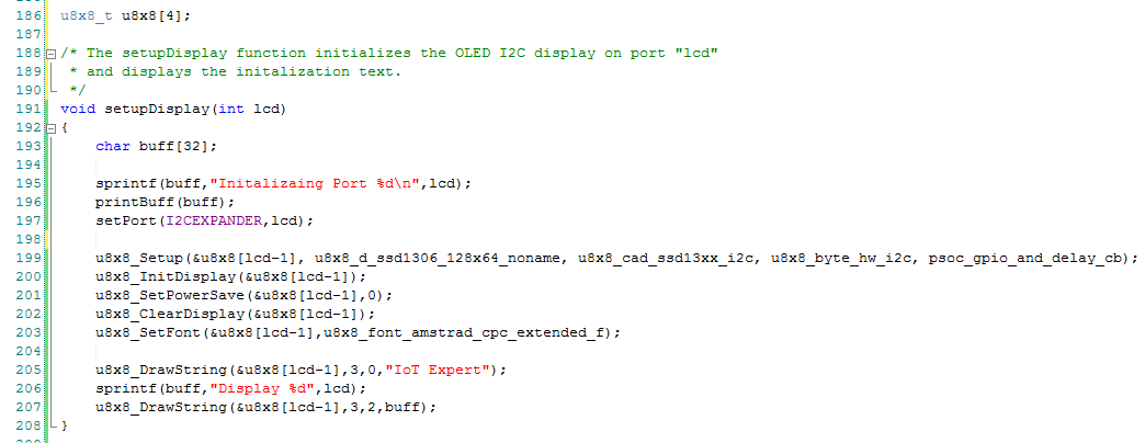
The cool thing about the whole setup with the I2CHUB is that it allows you to have 4 devices with the same I2C address attached to one PSoC SCB at the same time. To get going with the firmware, I start by defining an array of u8x8_t structures to represent the 4 different displays attaches to the 4 different ports on the I2C hub. (line 186). Then I create a function called setupDisplay that initializes the display etc. (lines 199-203). The only trick in the firmware is that Dennis Ritchie defined arrays to run from 0-3 but the I2C busses are labeled 1-4, this is the reason for subtracting 1 from the input lcd number.
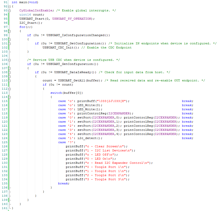
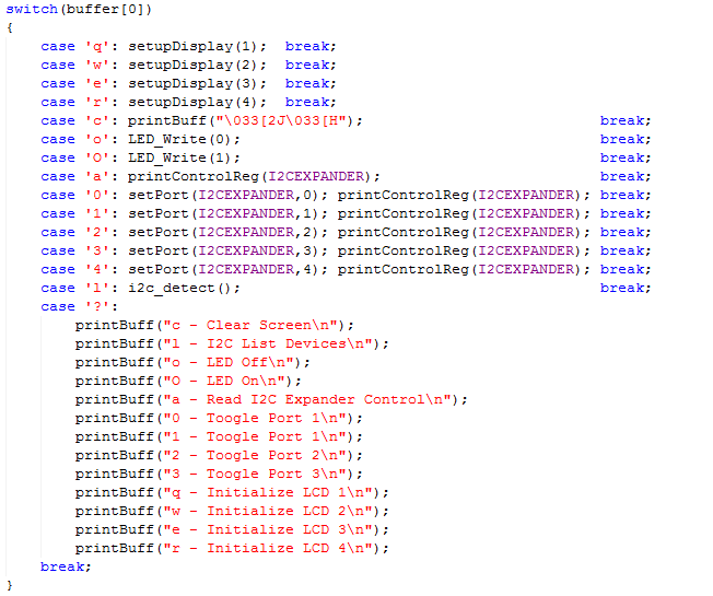
The next step is modifying command processors in the main loop. Specifically, I will add the commands q,w,e,r to startup the displays on I2C ports 1,2,3,4. And, I will add those commands to the help print out.
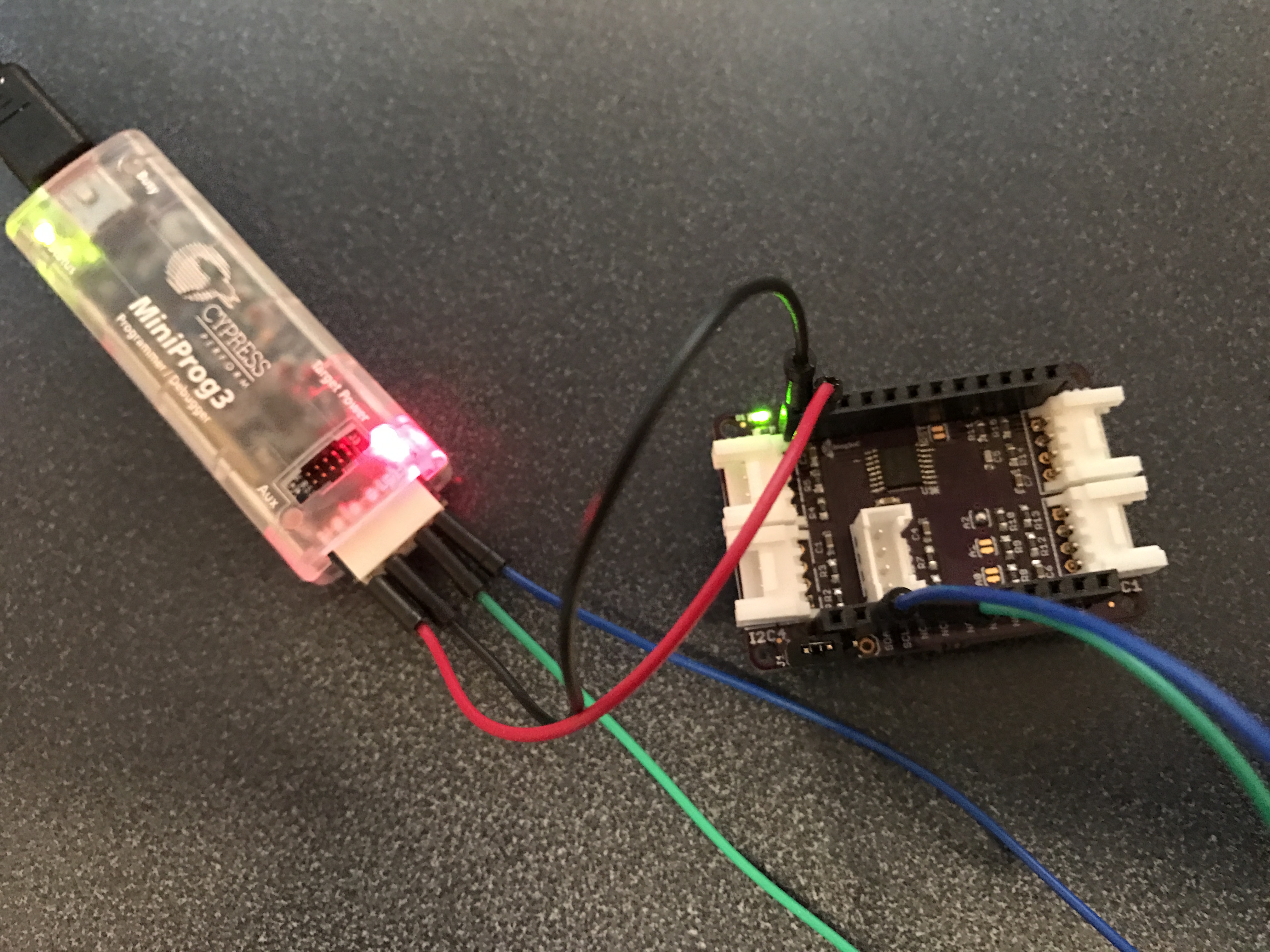
Test the PSoC4L Firmware
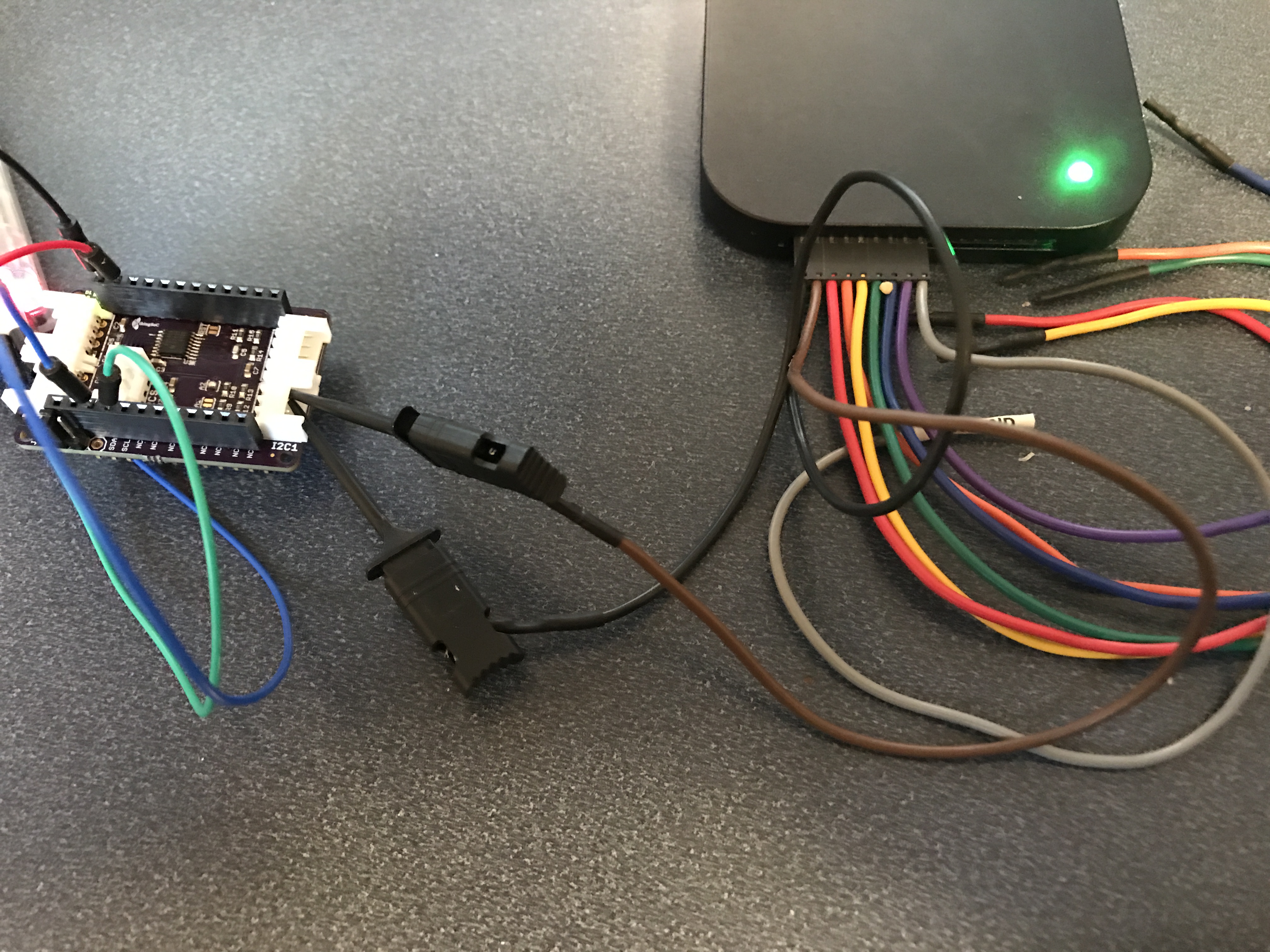
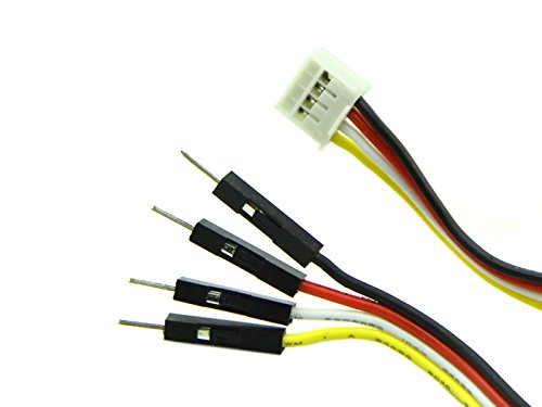
In order to make a connection from the Grove 4-pin connectors to my breadboard I used Switch Doc Labs connectors which I bought from Amazon.com. For some reason you can’t purchase them from the Switch Doc Labs website or the SeeedStudio website, but they are very handy. As an unrelated side note I had never seen (or in fact ever heard of) Switch Doc Labs. But their website has a bunch of tutorials about the Raspberry Pi and Grove ecosystem boards for use with IoT-ifying house plants. Seemed pretty cool.
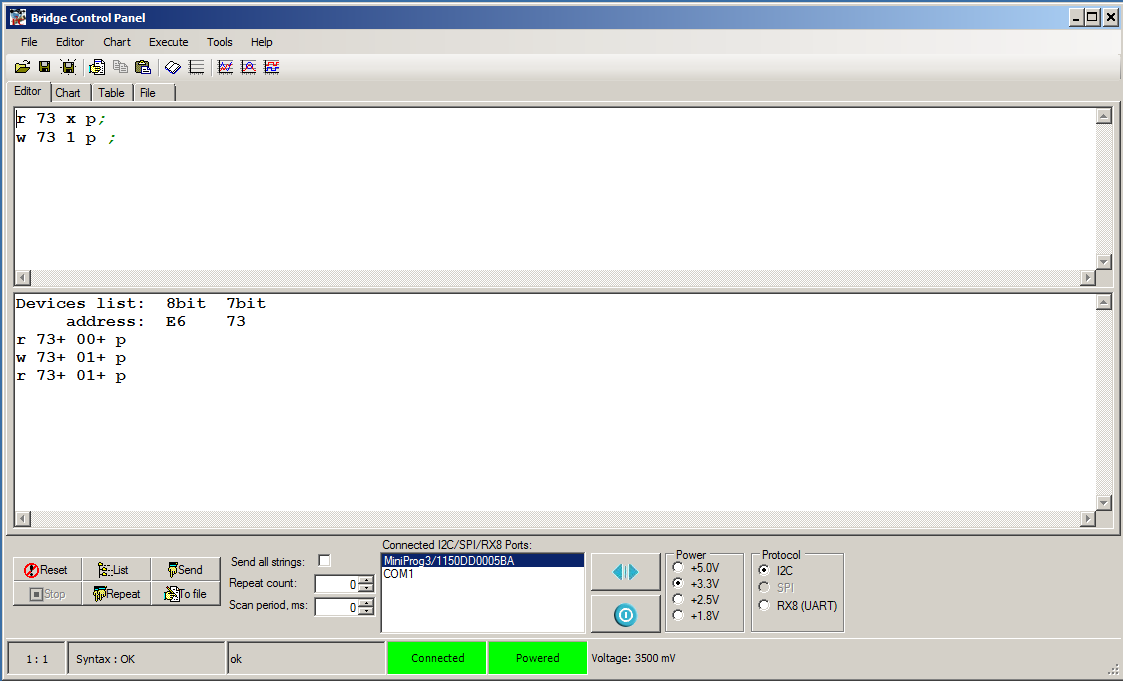
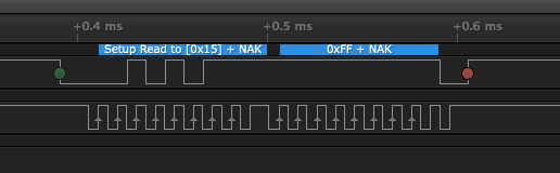
Now when I press “qwer” in my command console I get this:
You can find all of the projects in the TSoC Series at my GitHub ThingSoC repository git@github.com:iotexpert/ThingSoC.git
Index
Description
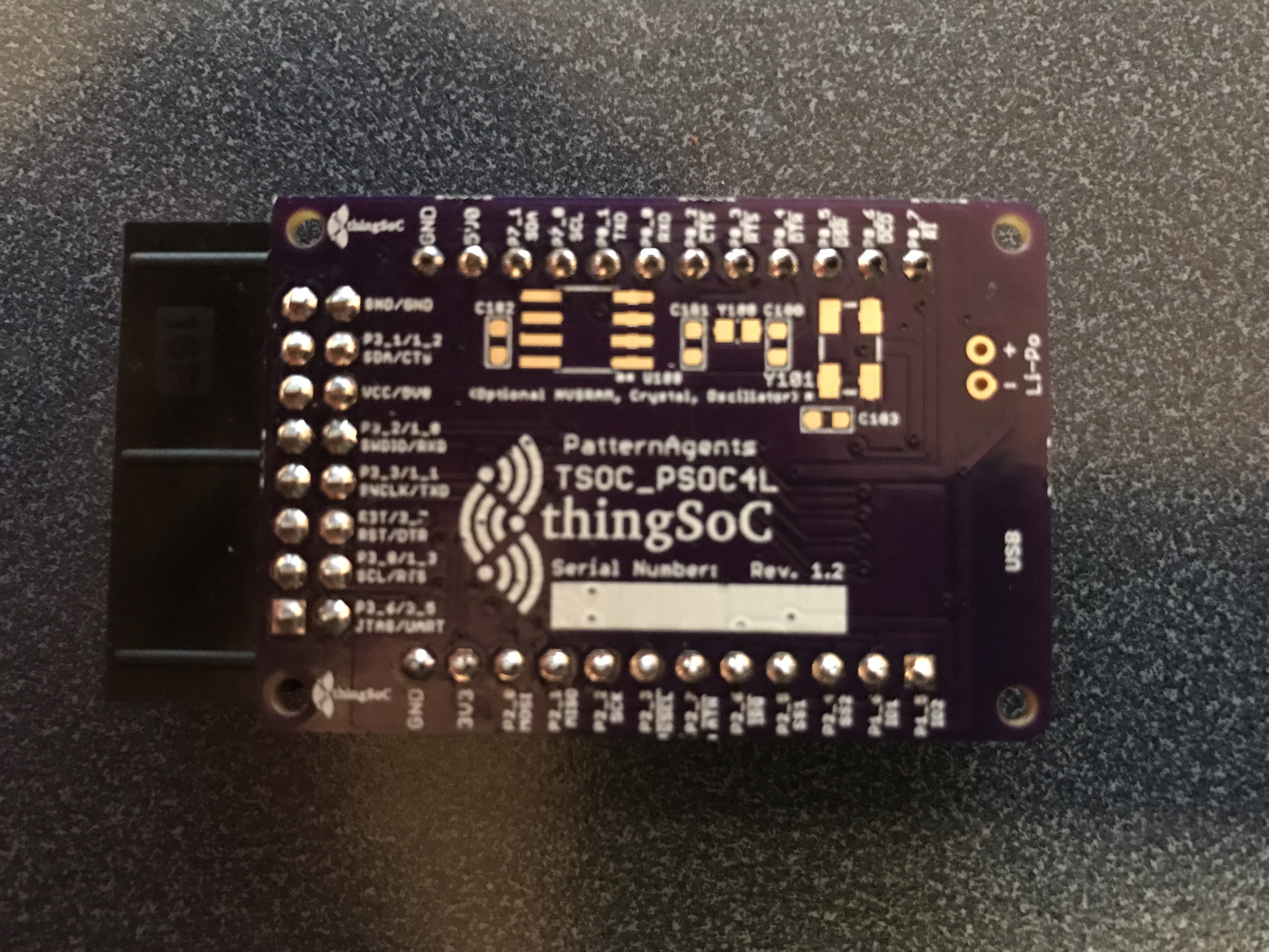
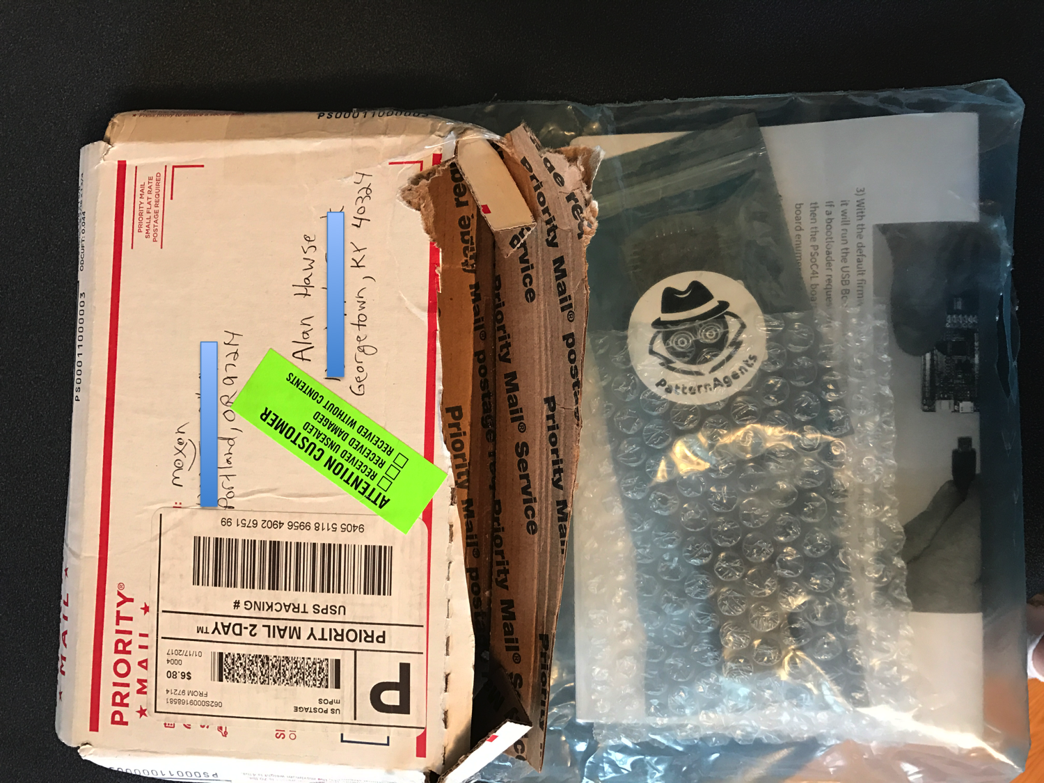
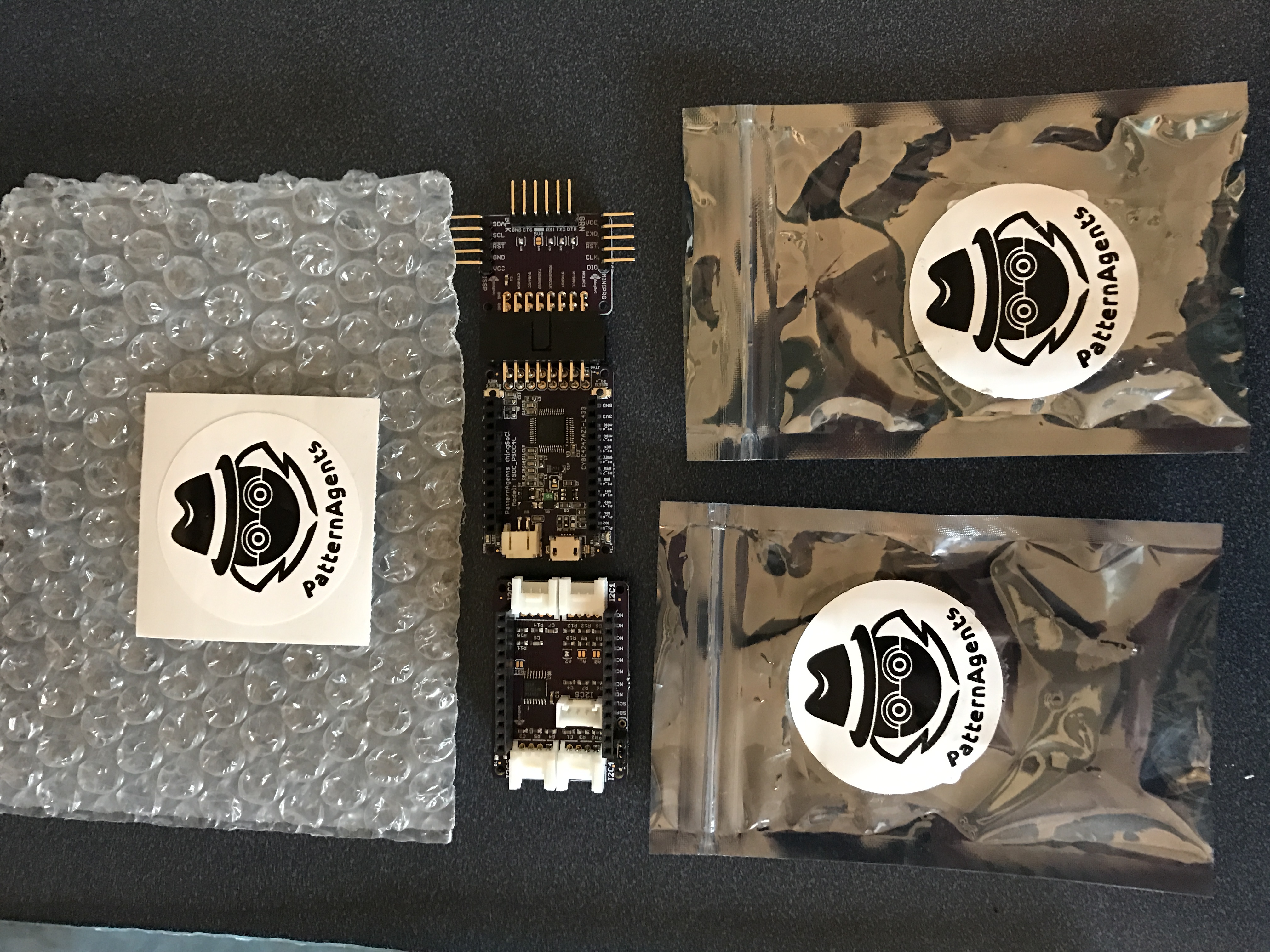
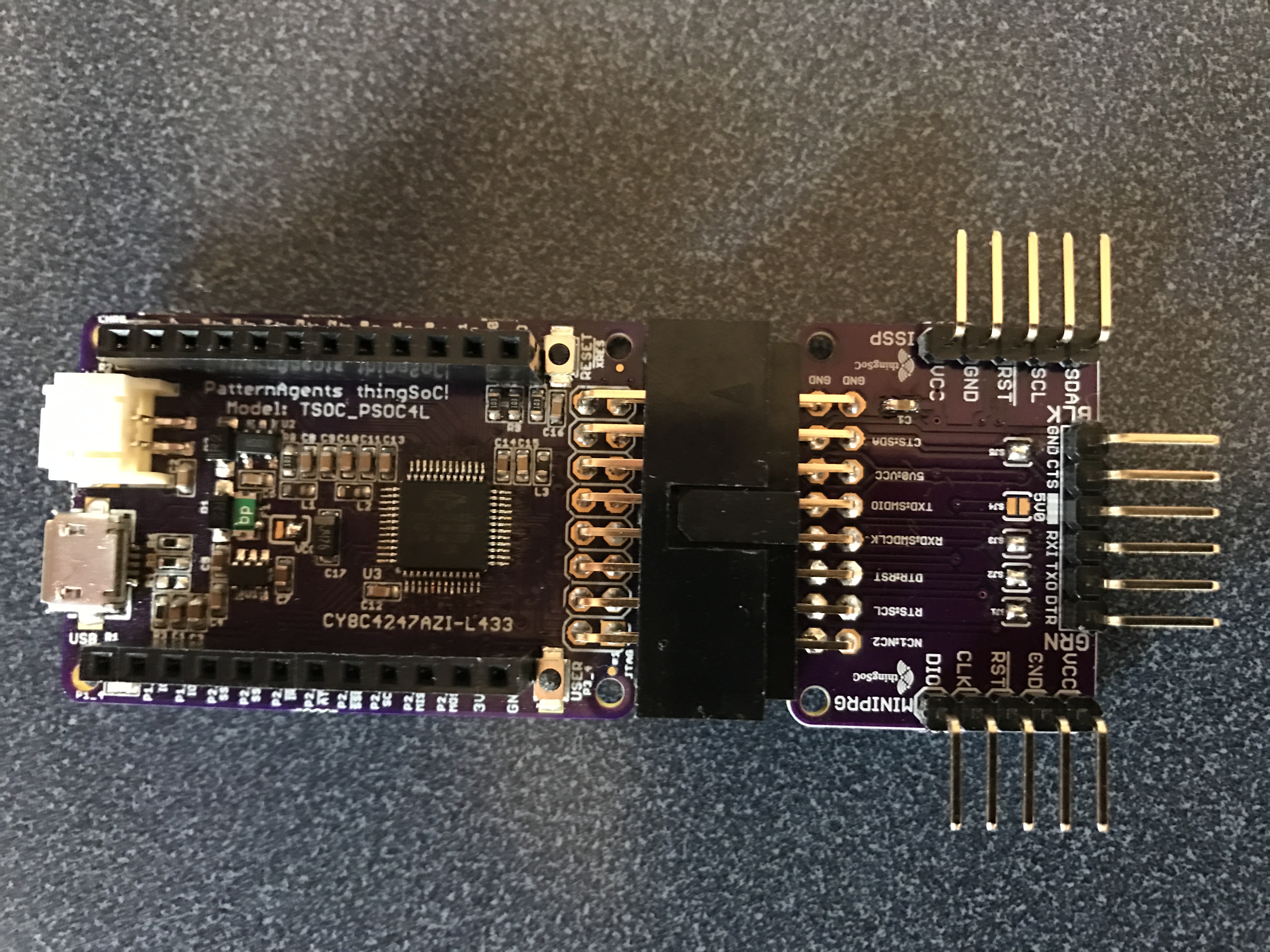
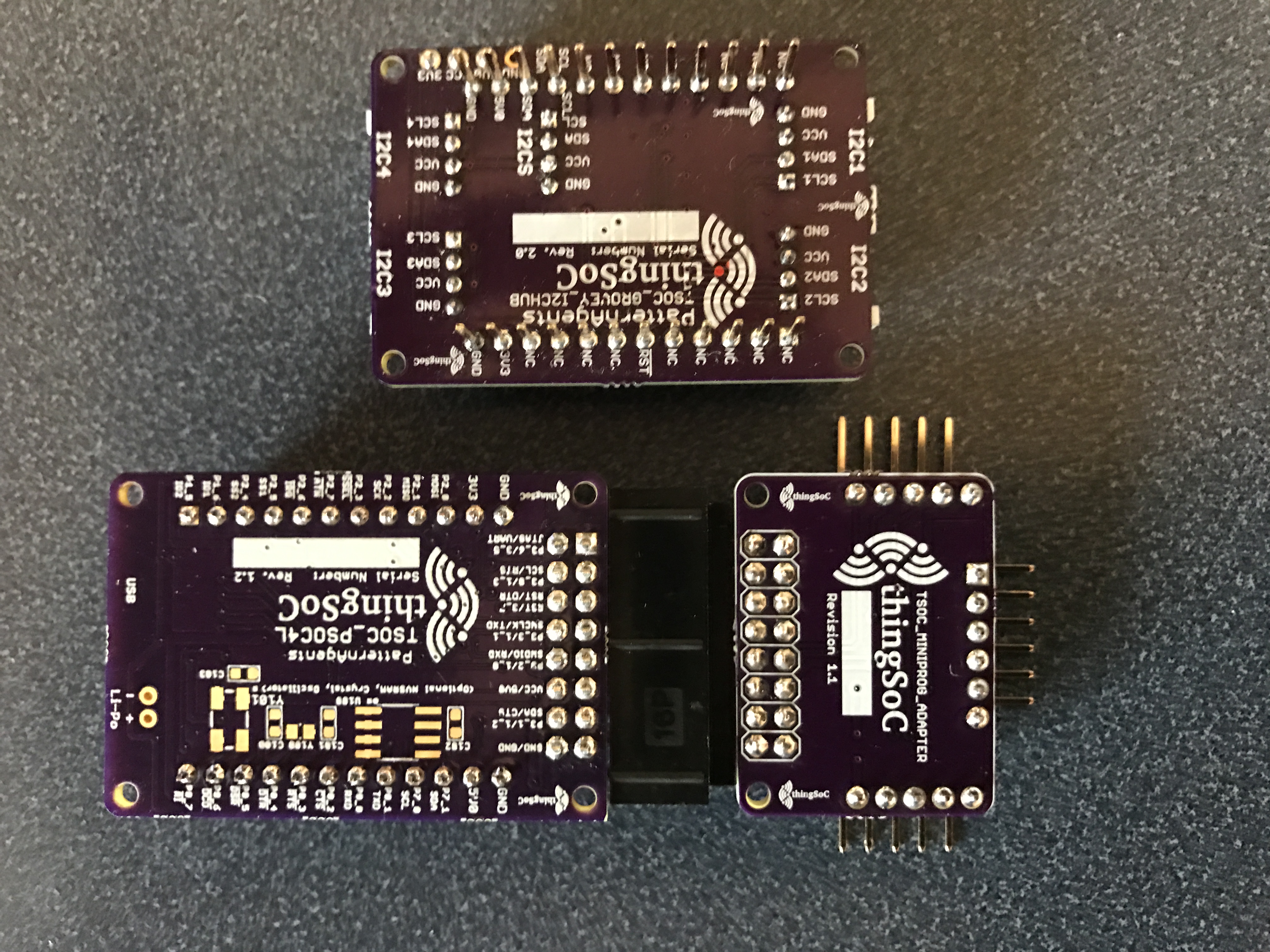
ThingSoc: TSoC PSoC4L Development Kit from PatternAgents
Introduction to ThingSoC
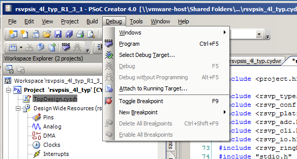
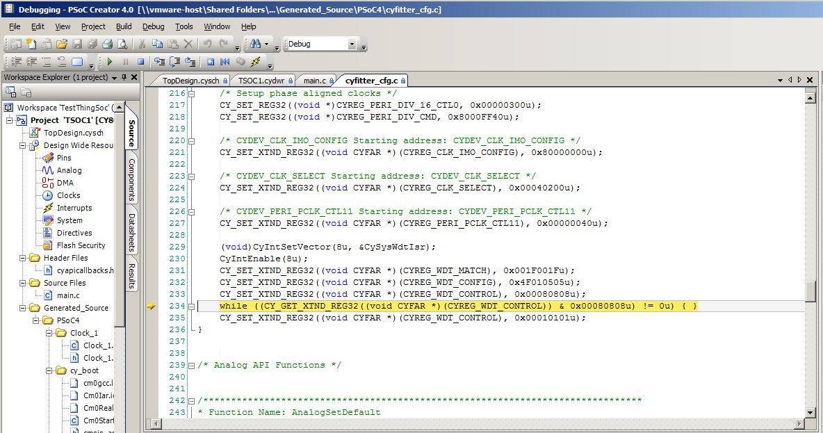
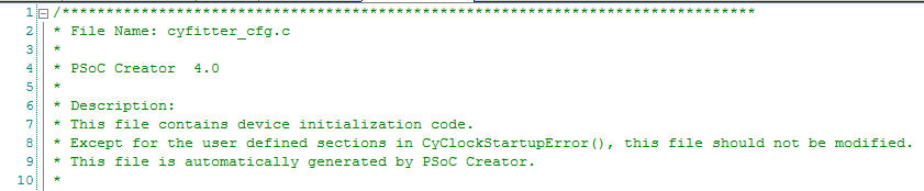
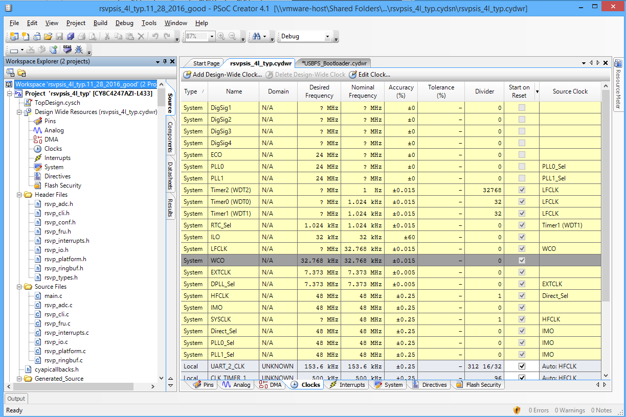
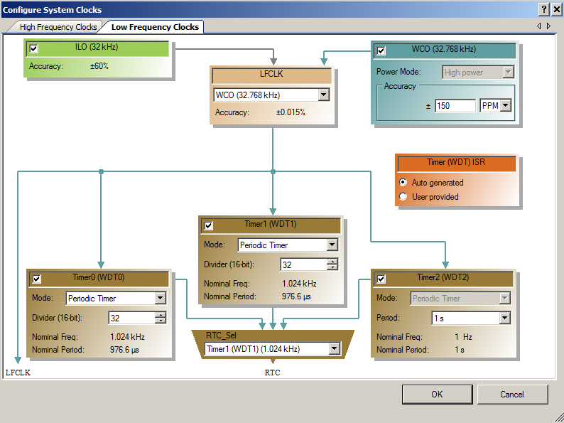
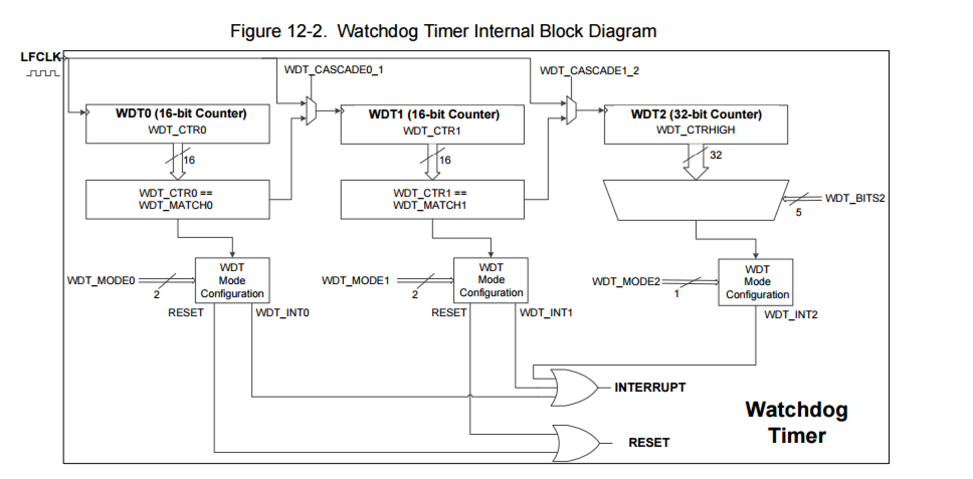
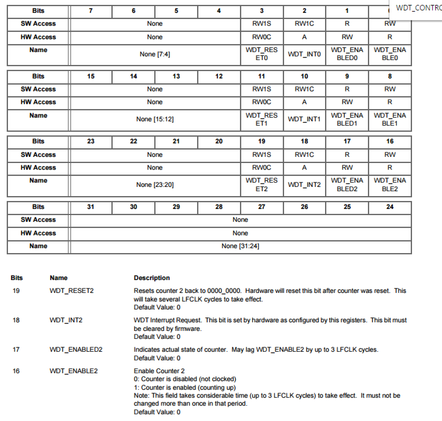
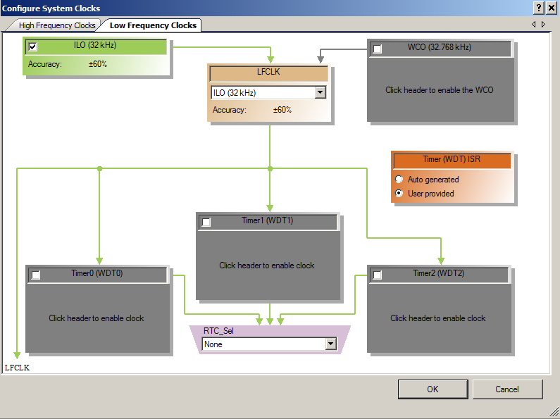
ThingSoC PSoC4L: Using & Debugging the PSoC4 Clock
Debugging a beta firmware problem
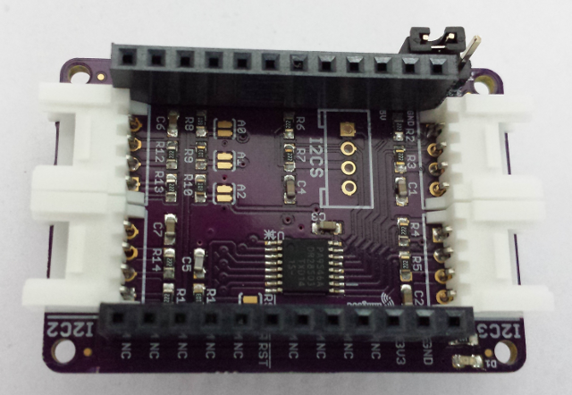
ThingSoC: The TSoC GROVEY I2CHUB : I2C Hub/Switch
Evaluating the ThingSoC I2C Hub
ThingSoC: Multiple I2C Displays
Using the I2CHUB and U8X8 Library
A project using ThingSoC I2C Hub & 4 OLED Displays