Bus Pirate V4 (SeeedStudio)

In the previous two Bus Pirate posts, I introduced the Bus Pirate and talked about the V3 version from Sparkfun, and I showed how to use the V3 version from Seeedstudio to read and write I2C commands into a Cypress FRAM.

Bus Pirate V4 is a complete redesign of the hardware.  It combines the PIC microcontroller and FTDI USB/Serial bridge into a single chip (a PIC 24FJ256GB106).  Mr. Lesnet also added 3.3v and 5.0v on board regulated voltages, and an onboard eeprom for extra storage.  You can read more on the Dangerous Prototypes web page.

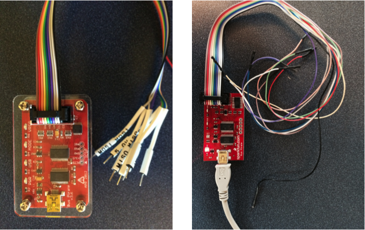
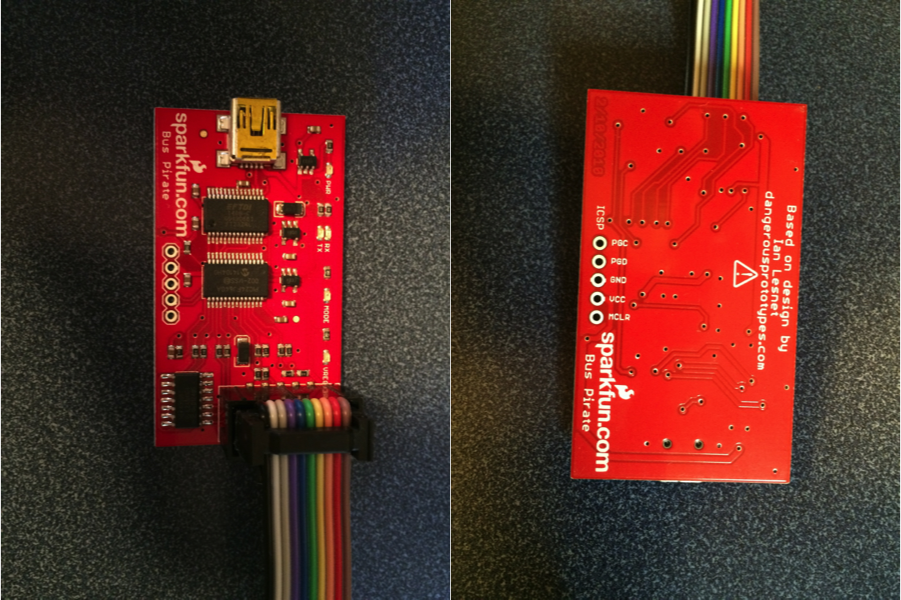
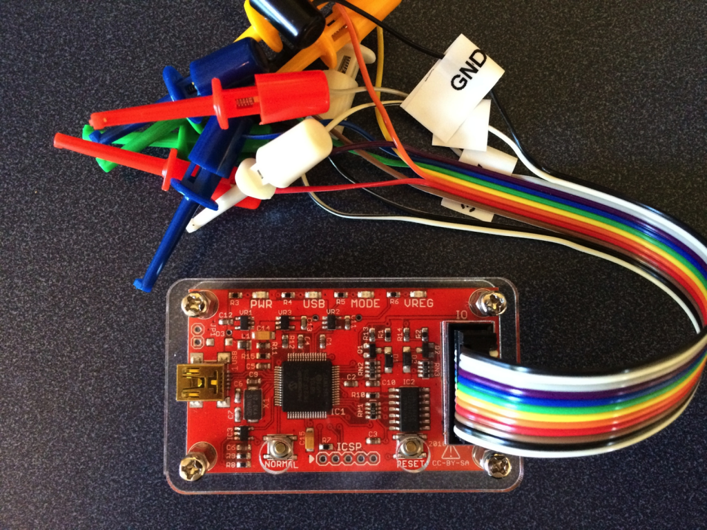
I also ordered the acrylic case (which is cool) as well as the V4 cable (which sucks compared to the V3 cable because the grabbers don’t match the cable color and are signals are unlabeled).

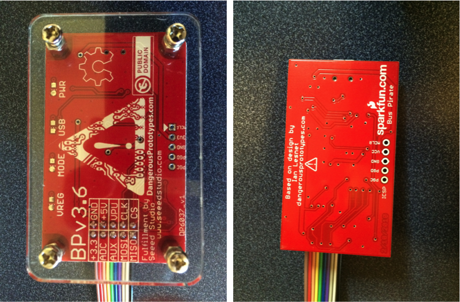
front

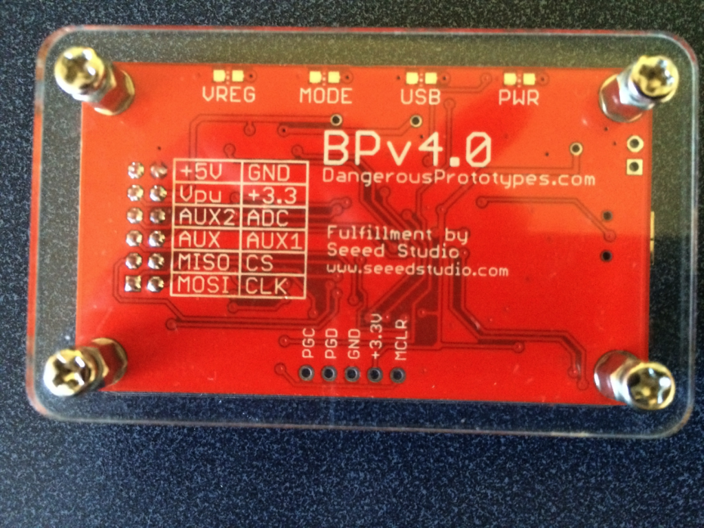
On the back of the board you can clearly see the right way to put a silkscreen on a board.  Clear, sensible, legible.

back

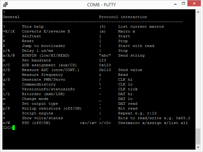
The first thing that I did was “?” to see what was new on the menu.

v4help

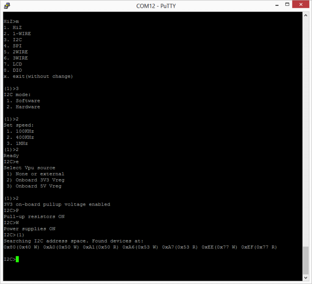
The next thing that I tried was putting the BP into I2C mode.  This was similar to V3 with the exception that now there is a hardware driven I2c and it is capable of 1MHz operation.  The other thing that has been added is a programmable onboard power supply.  You can select either 3.3v or 5.0v by using the “e” command.  The power supply can be turned on/off using “w” (off) and “W” (on).

setupi2c

Here is a screenshot of the schematic for selectable regulated pullup.

schematic

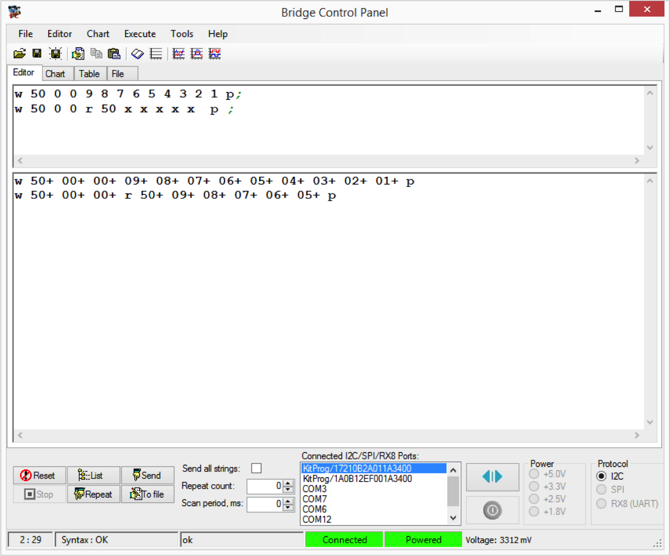
I was interested in trying the Bus Pirate I2C sniffer.  To do this I used the onboard I2C bridge in the “KitProg” on the CY8CKIT042 and used the Cypress Bridge Control Panel (part of PSoC Programmer) to issue I2C commands to the FRAM on my test setup (which is the same as in the previous posts).  In the example below I first issue a “Write, location 0x00, data 9,8,7,6,5,4,3,2,1”  In other words fill up the first 9 locations in the FRAM with 9..1.

The second command issues a “write, location 0x00, Read the next 5 bytes (each “x” reads 1 byte)”.

In the 2nd part of the Bridge Control Panel you can see the actual commands that happened on the bus and the ACKs (“+”) and responses from the FRAM.

bcp

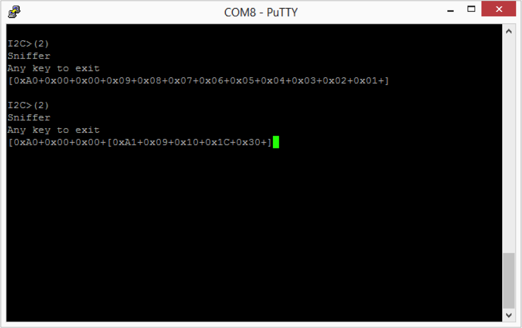
In the screenshot below you can see that the sniffer perfectly “sniffs” the first command.  That is pretty cool… and a very useful function.

In the second case, you can see that the BP sniffer can see the write command perfectly and can read the first byte response from the FRAM perfectly, but does not read the other bytes correctly.  Specifically it reads 0x10, 0x1c and 0x30 instead of 0x08, 0x07, and 0x06.

sniffer

To debug this problem I plugged in my Tektronix MSO2024B logic analyzer to see if there was some problem with the I2C transactions.  However, you can see from the screenshot below that the scope can read transactions perfectly.  So, what is going on?  I don’t know.  But, at this point it seems clear that the sniffer is a bit flaky.  At this point that is going to be a problem for another day.
scope

Bus Pirate V3 (SeeedStudio)

In the previous post, I introduced Bus Pirate  V3 – specifically the Sparkfun version.  After digging through things a little bit I decided to order the SeeedStudio V3 Bus Pirate.  This version has exactly the same firmware, pinout etc as the Sparkfun version.  However, there are a few good improvements in the SeeedStudio version.

First, the silkscreen on the SeeedStudio board is WAY better.  There is no good excuse for having a bad silkscreen on your board.  When you compare the two boards you can easily see the labels that clearly document the pins.

sidebyside

Second, the cable that you can get from SeeedStudio has beautiful heat shrink labels on the end of the cable.  And, more importantly the colors match the pins on the board.  In the picture the below the SparkFun cable colors are correct because I uncrimped the cable and fixed it as I described in the previous post.

side-by-side-top

And lastly, the SeeedStudio version is compatible with their acrylic case which is inexpensive and works well.  It is just two pieces of acrylic that have been laser cut to fit the BP.  Nice.

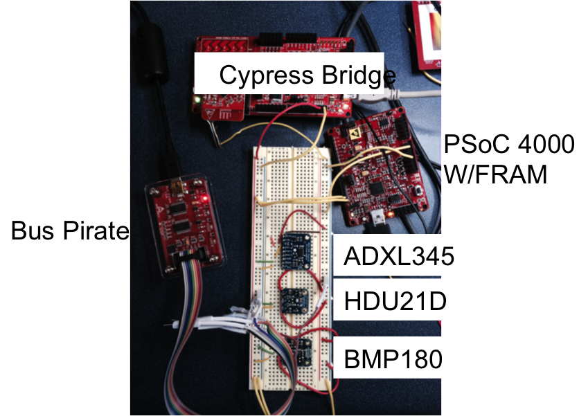
For my project I have:

  1. An FM24V10 FRAM from mounted onto a PSoC 4000 development kit from Cypress
  2. An ADXL345 3-Axis accelerometer mounted on an breakout board from Adafruit.
  3. An BMP180 Barometric pressure and temperature sensor on a breakout board from Adafruit
  4. A HDU-21D-F Humidity and temperature sensor on a breakout board from Adafruit

Here is the schematic:

schematic

And, here is a picture of the crazy breadboard.

breadboard1


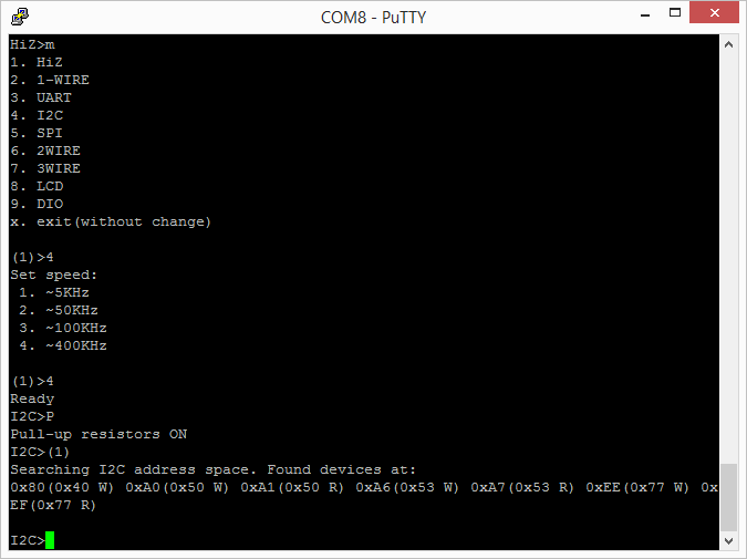
When you attach a terminal program – like Putty – to the usb serial port of the Bus Pirate, you are given a command prompt (press enter to get the prompt).  The first prompt that you get is “HiZ” which indicates that all of the pins of the BP are in high impedance mode.  Then, I issue the “m” command which tells the BP that I want to switch the mode.  I select “4” to put the BP into I2C mode.  I then select “4” to pick 400khz.  Notice that the BP says “~400kz” which almost certainly means that the I2C is implemented with bit banging.  Then I turn on the I2C pullup resistors  using the “P” (capital P) which are on the BP board.  In order for them to work you need to attach the “VPU” pin to either 3.3v or 5.0v.  The last command that I issue is a macro, all the macros are  enclosed in parenthesis.  The macro that I issue is “(1)” which searches the I2C address space (addresses 1-127) and makes a list of all of the devices that respond.

i2csetup

In my setup there are 4 I2C devices

Devices
Device 7-bit address 8-bit read 8-bit write
FRAM 0x50 0xA1 0xA1
ADXL345 0x53 0xA7 0xA6
BMP180 0x77 0xEF 0xEE
HTU21 0x40 0x81 0x80

In order to write to the FRAM you need to issue:

  1. An I2C Start – in BP that means “[“
  2. The 7-bit I2C address of the FRAM (0x50) and the write bit “0”.  AKA 0xA0
  3. The two byte address of where you want to start writing data in the FRAM 0x00 and 0x00
  4. The data – in this case 9,8,7,6,5,4,3,2,1 (which means that locations 0-8 will contain 9..1)
  5. An I2C stop – in BP that means “]”

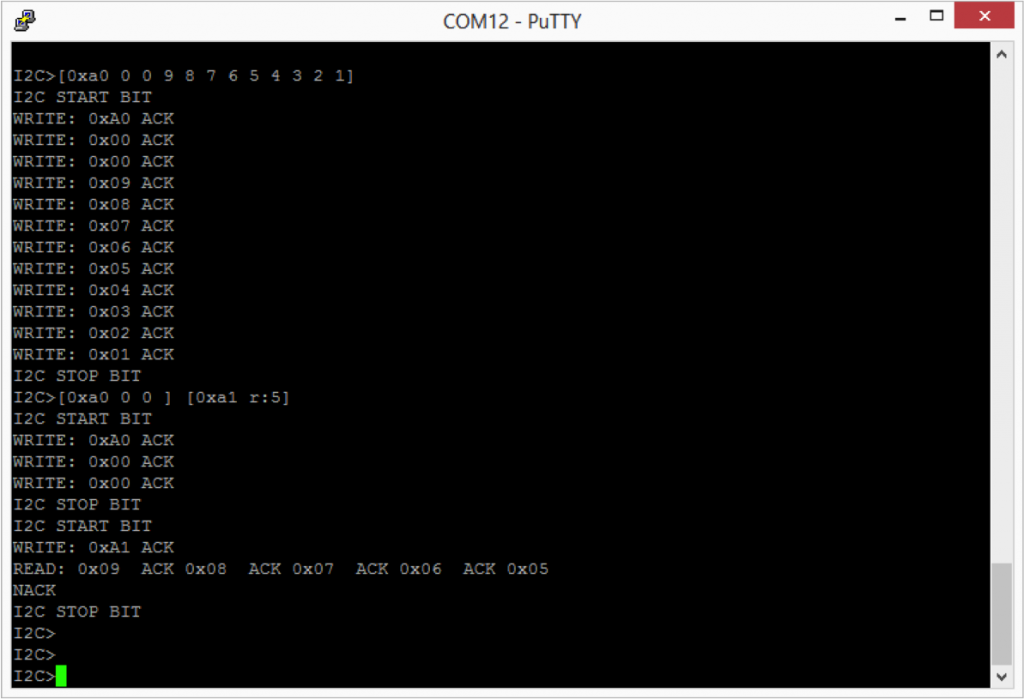
After issuing this sequence “[0xa0 0 0 9 8 7 6 5 4 3 2 1]” you can see the commands that are actually issueed on the I2C bus as well as the slave FRAM responding with “ACK”.

i2c-commands

The second example which you can see in the above screen shot is to read from the FRAM.  In order to do this you need to issue the following I2C commands

  1. An I2C Start – “[“
  2. The 7-bit I2C address of the FRAM (0x50) and the write bit “0”.  AKA 0xA0 (left shift the 0x50 and or it with the read 0x00)
  3. The two by address of where you would like to read 0x00 and 0x00
  4. An I2C Stop – “]”
  5. An I2C Start (aka Restart) – “[“
  6. The 7-bit I2C address of the FRAM (0x50) and the read bit “1”.  AKA 0xA1 (left shift the 0x50 and or it with the read 0x01)
  7. 5 reads

After issuing this sequence “[0xa0 0 0][0xa1 r:5]” you can see the commands that are actually issued on the I2C bus as well as the slave FRAM responding with the data in the FRAM and the “ACKs”.

In the next post I will introduce the V4 Bus Pirate.

Bus Pirate V3 (from Sparkfun)

One of the common open source development tools is called the Bus Pirate.  It is a low cost ($35) serial terminal based program that can issue commands to many (and mostly serial) busses including UART, SPI, 1-2-3 wire and I2C.  Bus Pirate was developed by Ian Lesnet of Dangerous Prototypes.

I am currently working on a project for a friend of mine  (more to come on this topic) that will read data from 3 different I2C sensors, record the data into a nonvolatile RAM and simultaneously broadcast it over a BLE Radio.  As such, I had a need to make sure that I understood the way that these sensors behave.

The bus pirate has had 4 major revisions and many subrevisions.  The current “stable” version is V3, however, there is a fairly new version V4 which has many improvements and should soon displace V3.

Initially I bought a V3 bus pirate from Sparkfun and the Sparkfun cable,  which I thought would be cool. sparkfun

I started by plugging the BP into a USB port, where it proceeded to enumerate as something my computer had never seen before.  Great.  I looked  around a bit and figured out that the designer had used a FTDI USB to Serial bridge chip as part of the design.  This chip required a custom driver which I found on FTDIs driver website.  This requirement was also documented in the Bus Pirate 101 tutorial.  It is kind of too bad that FTDI hasn’t gotten their driver to be understood by Windows without intervention.  Just one more good reason to use the Cypress USB Serial Chip.

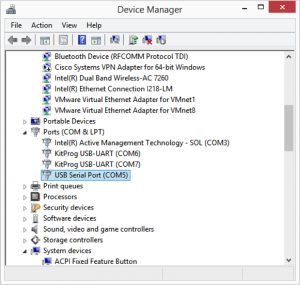
After sorting out the driver situation I attached to the Bus Pirate using my favorite terminal program – Putty.  You can see (by looking at the Device Manager) that the BP enumerated as COM5 on my computer.

devicemanager

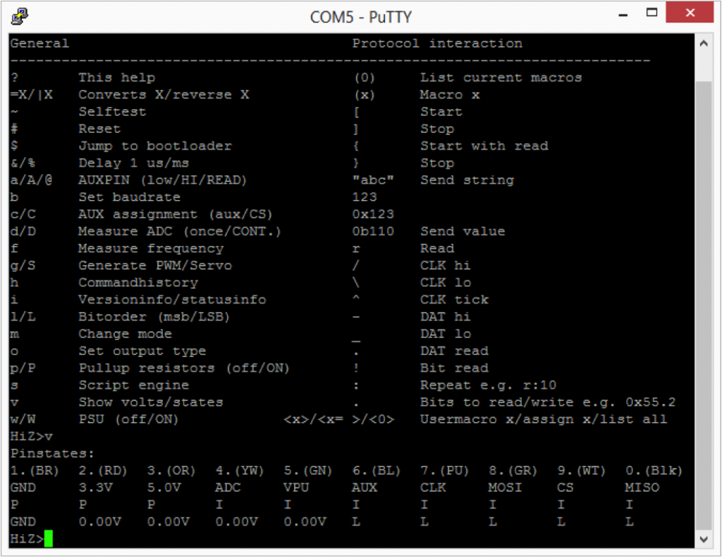
The first thing that I tried (without having yet looked at the instructions was “?” which nicely gave a list of the commands (as you can see in the screenshot below).

screen1

I then tried “v” which shows the states of the 10 pins.  Cool.  My first though was “which wire on this cable is pin 1?”  Then I looked at the screen and realized “wow… look at that, the wires on the cable are the same color as the labels on the screen”.  I though that was pretty damn civilized.  I had a variable voltage sitting right next to the kit (just a POT on another devkit that I was working on) so I plugged it into the “YW” (aka Yellow) wire.  After pressing v again it happily reported 0.00v (two decimal places even).  Hmmm… what in the world is going on.   Time for the fluke.  Crazy, the voltage is right, I wonder what isnt working.  I then guessed that the cable was plugged in backwards, but that wasnt it (the cable is keyed).  Then I wondered if there was something wrong with the cable, so I disconnected it and just connected directly to the pin (which is unlabeled on the silkscreen – that sucks).  I found the pinout on the schematic on Dangerous Prototypes.  Then I realized, the cable is BACKWARDS from the real pinout.  That really really sucks.

When I looked at the comments on the Sparkfun page there is quite the little discussion about this topic.  Included is a suggestion to un-crimp the cable, flip it over, and recrimp.  I tried this suggestion and it worked out, until I broke part of the plastic holding the cable together.  After getting the voltage source connected to pin 4 I was able to see changes in the value being read correctly by the analog to digital convertor in the BP.  Cool.

The other comment which caught my attention on the Sparkfun page was a request from Ian Lesnet to please buy from the SeeedStudio website.  This motivated me to purchase another V3 and a V4 from SeeedStudio.  I the next post Ill talk more about my experience with SeeedStudio V3 and V4.