Summary
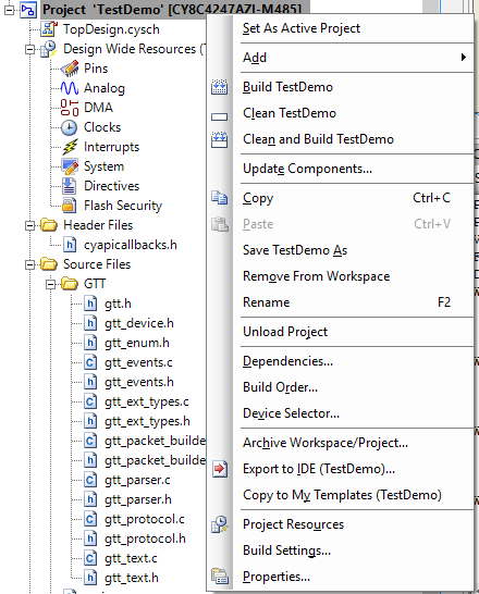
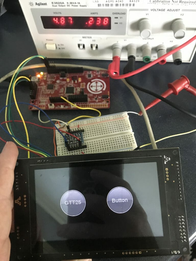
In the previous article I showed you how to integrate the Matrix Orbital Driver into a PSoC4200M project. I am planning on using this device on a bus with multiple displays, and using an RTOS. The byte based driver in the previous example isn’t that great for this situation. In one of the earlier articles I showed you how to build a packet based interface instead of a byte-based interface. Lets integrate that into the PSoC4200M project, and add some more commands.
In this article I will
- Integrate the packet driver
- Add event handlers
- Add some new commands
- Fix a nasty little bug that is lurking in the driver
Integrate the Packet Driver
In the file gtt_parser.c there is a big long function which reads a byte at a type every time that it is called. It then assembles the packet into a buffer of bytes that the rest of the system can consume. After the packet is completely read, it sets up pointers to the start and end of the packet and finally calls the function “gtt_process_packet”. For me what I will do is read in a packet, then call this function to setup things and call the gtt_process_packet.
// This function process a whole packet at a time
uint8_t gtt_parser_process(gtt_device *device)
{
    gtt_packet_error_t rval;
    rval = device->ReadPacket(device);
    if(rval == GTT_PACKET_NODATA)
        return 0;

    if(rval != GTT_PACKET_OK)
    {
#if DEBUG_PSOC
        sprintf(buff,"GTT_PACKET_ERROR %d\r\n",rval);
        UART_UartPutString(buff);
#endif
        return 0; // No data
    }

    device->Parser.PacketStart = device->Parser.Index;
    device->Parser.Index += device->Parser.Length;

	uint8_t Result = gtt_process_packet(device, device->Parser.PacketStart);
	if (Result)
	    return 0;
	else
	    return 1;

}
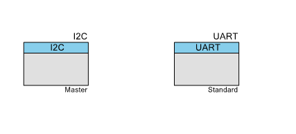
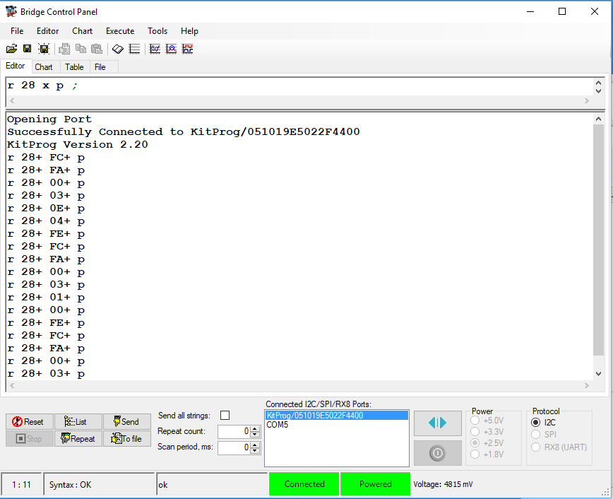
I use almost the same packet driver as I built in the earlier example. Except that I need to modify it to read into the gtt buffers that the gtt driver library expects. The biggest benefit of this whole thing is that it makes complete I2C transactions, rather than issuing a bunch of start/address/reads which makes it significantly more efficient.
gtt_packet_error_t readPacketI2C(gtt_device *device)
{
uint8_t data;
uint32_t i2cerror;
i2cerror = I2C_I2CMasterSendStart( ((i2cContext_t *)device->Context)->slaveAddress,I2C_I2C_READ_XFER_MODE , ((i2cContext_t *)device->Context)->timeout);
i2cerror |= I2C_I2CMasterReadByte(I2C_I2C_NAK_DATA,&data,((i2cContext_t *)device->Context)->timeout);
i2cerror |= I2C_I2CMasterSendStop(((i2cContext_t *)device->Context)->timeout);
// Something bad happened on the I2C Bus ....
if(i2cerror)
{
sprintf(buff,"I2C Return Code %X\r\n",(unsigned int)i2cerror);
UART_UartPutString(buff);
return GTT_PACKET_I2CERROR;
}
// The screen returns a 0 when there is nothing in the buffer.
if(data == 0)
{
return GTT_PACKET_NODATA;
}
// This is bad because there was something other than a packet start byte
if(data != 252)
{
sprintf(buff,"bad data = %d\r\n",data);
UART_UartPutString(buff);
return GTT_PACKET_DATABAD;
}
// We know that we have a command
i2cerror = I2C_I2CMasterSendStart( ((i2cContext_t *)device->Context)->slaveAddress,I2C_I2C_READ_XFER_MODE , ((i2cContext_t *)device->Context)->timeout);
i2cerror |= I2C_I2CMasterReadByte(I2C_I2C_ACK_DATA,&data,((i2cContext_t *)device->Context)->timeout); // command
device->Parser.Command = data;
// Read the Length
i2cerror |= I2C_I2CMasterReadByte(I2C_I2C_ACK_DATA,&data,((i2cContext_t *)device->Context)->timeout); // length
device->Parser.Length = data<<8;
i2cerror |= I2C_I2CMasterReadByte(I2C_I2C_NAK_DATA,&data,((i2cContext_t *)device->Context)->timeout); // length
device->Parser.Length += data;
i2cerror |= I2C_I2CMasterSendStop(((i2cContext_t *)device->Context)->timeout);
if(i2cerror)
return GTT_PACKET_I2CERROR;
if(device->Parser.Length > device->rx_buffer_size)
{
return GTT_PACKET_SIZE;
}
// If the packet has any data... then read it.
if(device->Parser.Length != 0)
{
i2cerror |= I2C_I2CMasterSendStart( ((i2cContext_t *)device->Context)->slaveAddress,I2C_I2C_READ_XFER_MODE , ((i2cContext_t *)device->Context)->timeout);
for(uint32_t i=0;i < device->Parser.Length-1; i++)
{
i2cerror |= I2C_I2CMasterReadByte(I2C_I2C_ACK_DATA,&data,((i2cContext_t *)device->Context)->timeout); // length
device->rx_buffer[device->Parser.Index+i] = data;
}
// Read the last byte
i2cerror |= I2C_I2CMasterReadByte(I2C_I2C_NAK_DATA,&data,((i2cContext_t *)device->Context)->timeout); // length
device->rx_buffer[device->Parser.Index +device->Parser.Length - 1 ] = data;
i2cerror |= I2C_I2CMasterSendStop(((i2cContext_t *)device->Context)->timeout);
if(i2cerror)
return GTT_PACKET_I2CERROR;
}
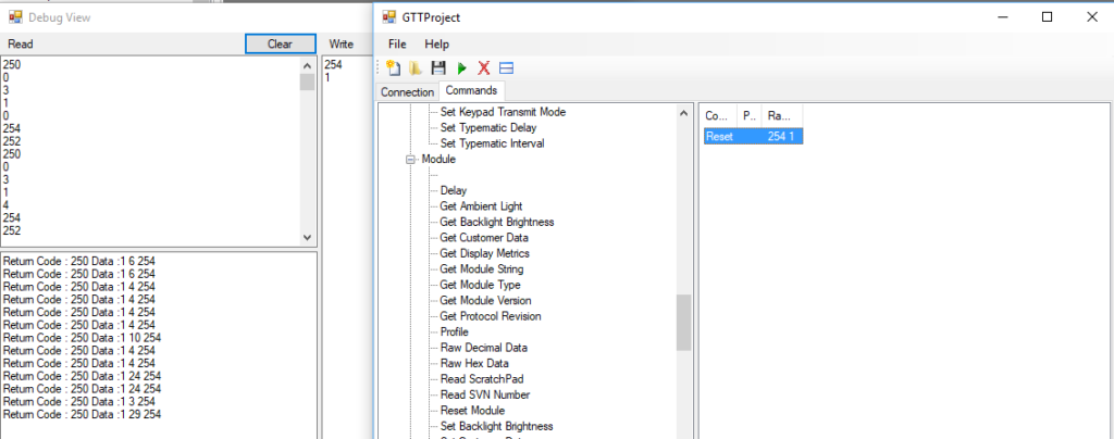
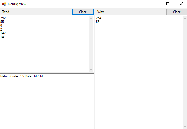
sprintf(buff,"command = %d length = %d bytes= ",device->Parser.Command,device->Parser.Length);
UART_UartPutString(buff);
for(uint32_t i=0;i<device->Parser.Length;i++)
{
//sprintf(buff,"%d ",inbuff[i]);
sprintf(buff,"%d ",device->rx_buffer[device->Parser.Index+i]);
UART_UartPutString(buff);
}
UART_UartPutString("\r\n");
return GTT_PACKET_OK;
}
Add Event Handlers
I noticed when I looked at the gtt_device.h that the structure for the gtt_device has an member called “gtt_events”, but what is that?
typedef struct gtt_device
{
	void* Context;            /* device depended storage */
	gtt_write Write;          /* Function for writing data */
	gtt_read Read;            /* Function for reading data */
    gtt_packet_error_t (*ReadPacket)(gtt_device *);

	uint8_t secured_packets;  /* 0 = regular protocol, 1 = wrap all outgoing packets with crc protection*/

	/* The fields below are internal and shall NOT be used by the read/write functions */

	gtt_parser Parser;        /* Protocol parser data */
	uint8_t *rx_buffer;       /* Buffer for incoming data */
	size_t rx_buffer_size;    /* size of the rx buffer in elements */
	uint8_t *tx_buffer;       /* Buffer for outgoing data */
	size_t tx_buffer_size;    /* size of the tx buffer in elements */
	size_t tx_index;          /* current index for the packet writer */
	gtt_events events;        /* Event Callbacks */
	size_t wait_idx;          /* Current Packet Index for the waitlist */
	gtt_waitlist_item waitlist[8]; /* Packet recieve waitlists */
} gtt_device;
Well. the gtt_events structure is defined in gtt_events.h. Basically it is a bunch of function pointers, which if you provide functions, it will call those functions when things happen on the screen. For instance the function that gtt_event_slider_change is pointing to will be called when a slider changes.
typedef void(*gtt_event_key)(gtt_device* device, uint8_t key, eKeypadRepeatMode type);
typedef void(*gtt_event_sliderchange)(gtt_device* device, eTouchReportingType type, uint8_t slider, int16_t value);
typedef void(*gtt_event_touch)(gtt_device* device, eTouchReportingType type, uint16_t x , uint16_t y);
typedef void(*gtt_event_regiontouch)(gtt_device* device, eTouchReportingType type, uint8_t region);
typedef void(*gtt_event_baseobject_on_property_change)(gtt_device* device, uint16_t ObjectID, uint16_t PropertyID);
typedef void(*gtt_event_visualobject_on_key)(gtt_device* device, uint16_t ObjectID, uint8_t Row, uint8_t Col, uint8_t ScanCode, uint8_t Down);
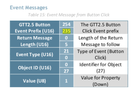
typedef void(*gtt_event_button_click)(gtt_device* device, uint16_t ObjectID, uint8_t State);
typedef struct gtt_events {
gtt_event_key key;
gtt_event_sliderchange sliderchange;
gtt_event_touch touch;
gtt_event_regiontouch regiontouch;
gtt_event_baseobject_on_property_change baseobject_on_property_change;
gtt_event_visualobject_on_key visualobject_on_key;
gtt_event_button_click button_click;
} gtt_events;
To start with I just created stub functions that would just print out the information. Here is an example of a function for the “gtt_event_button_click”
void my_gtt_event_button_click(gtt_device* device, uint16_t ObjectID, uint8_t State)
{
    (void)device;
    (void)ObjectID;
    (void)State;
    UART_UartPutString("event button click\r\n");
}
Once you have those functions you need to add them to the gtt_device structure like this:
gtt_events myEvents = {
    .sliderchange = my_gtt_event_sliderchange,
    .touch = my_gtt_event_touch,
    .regiontouch = my_gtt_event_regiontouch,
    .baseobject_on_property_change = my_gtt_event_baseobject_on_property_change,
    .visualobject_on_key = my_gtt_event_visualobject_on_key,
    .button_click = my_gtt_event_button_click
};
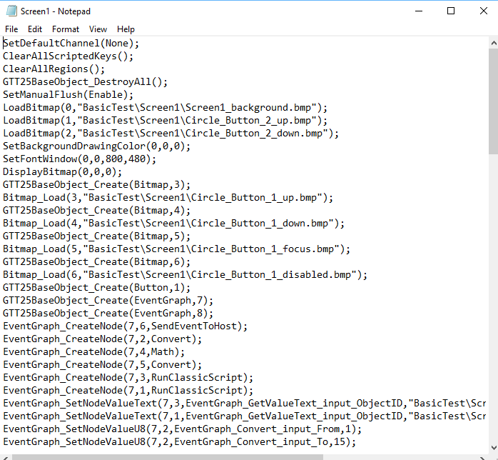
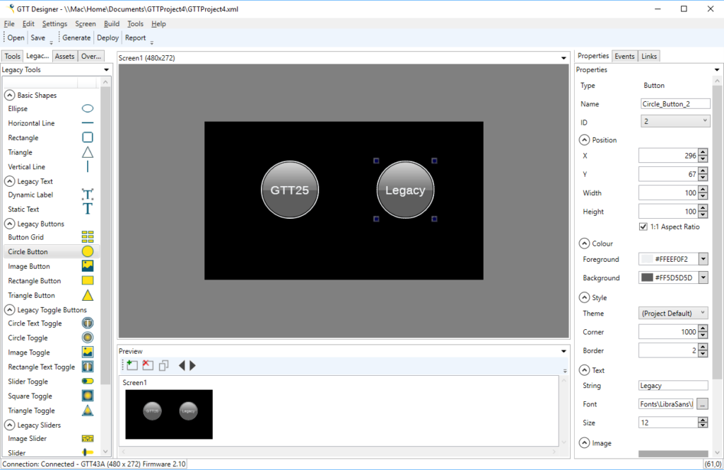
Add New Commands
Now we are ready to update the test project to add some more commands. Here are a few examples which call the “gtt25” functions.
case 'q':
UART_UartPutString("Set Text\r\n");
gtt25_set_label_text(gtt,2,t);
break;
case '2':
gtt25_set_slider_value(gtt,3,2);
break;
case '9':
gtt25_set_slider_value(gtt,3,9);
break;
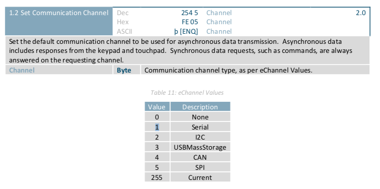
case 'I':
gtt_set_default_channel(gtt, eChannel_I2C);
break;
case '+':
count += 1;
if(count>100)
count = 100;
gtt25_set_gauge_value(gtt,9,count);
break;
case '-':
if(count > 0)
count -= 1;
gtt25_set_gauge_value(gtt,9,count);
break;
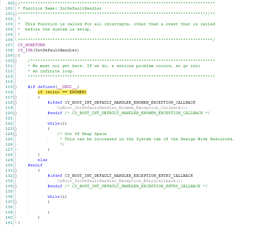
Fix a Nasty Little Bug
While I was debugging the library I found myself where the program was hung. When I ran the debugger I found myself here. This means that there was an ARM exception. But why?
Then when you look at the call stack you find out that the exception is in the function “gtt_parser_getS16”
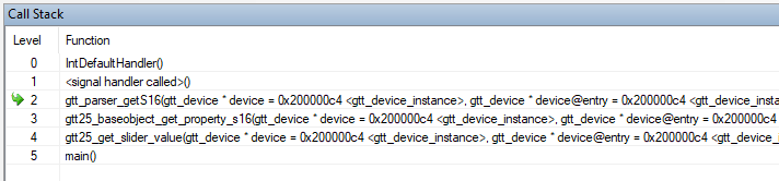
OK… but what in the world? All this function is doing is taking the bytes and casting them into a uint16_t

Well it turns out that if the address that is being read is ODD meaning not even aligned, you will endup with an ARM exception for an unaligned access of the memory. This is why you need to be super careful with a pointer cast. In this case you are casting a uint8_t pointer which can be byte aligned.
Here is a proper fix to this problem, assemble the composite type byte-by-byte.
int16_t gtt_parser_getS16(gtt_device* device, size_t index, size_t *outIndex)
{

    int16_t data = (device->rx_buffer[index]<<8 | device->rx_buffer[index+1]);
	*outIndex = index + 2;
    return data;

}
In the next article I will port all of this stuff to PSoC 6.
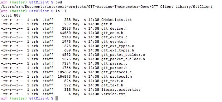
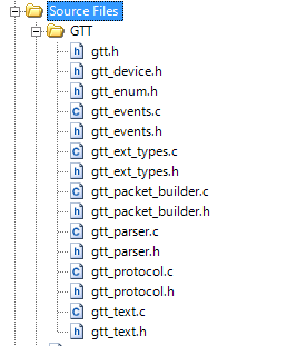
You can "git" these projects from https://github.com/iotexpert/GTT43A And the driver library from https://github.com/iotexpert/GTT-Client-Library
Title
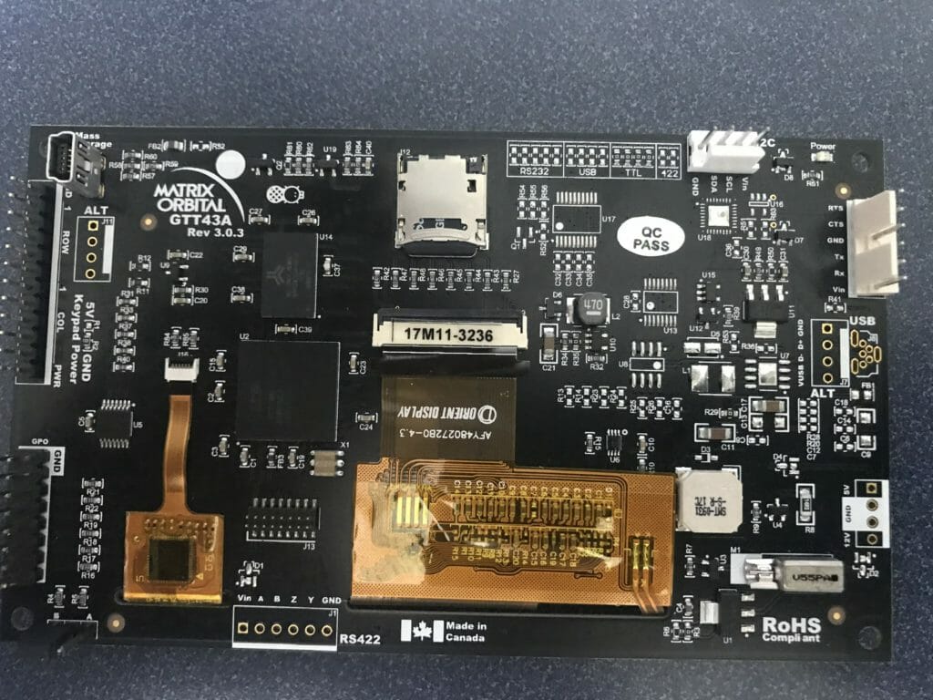
Matrix Orbital GTT43: A Cool Display
Matrix Orbital GTT43A: Serial Interface
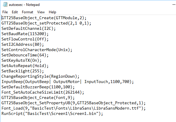
Matrix Orbital GTT43A: GTT Scripts
Matrix Orbital GTT43A: A PSoC 4 Interface
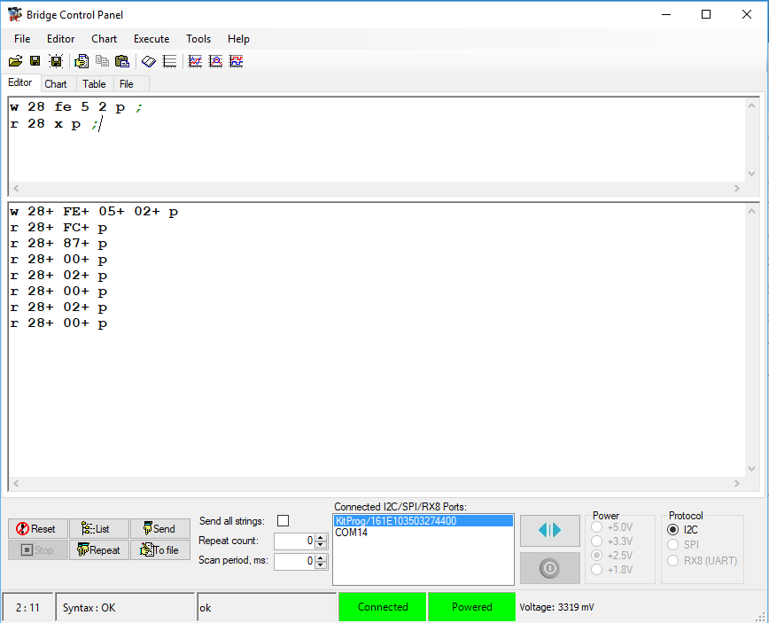
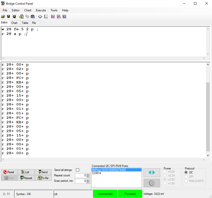
Matrix Orbital GTT43A: Debugging the I2C
Matrix Orbital GTT43A: GTT Driver Library - Part 1
Matrix Orbital GTT43A: GTT Driver Library - Part 1
Matrix Orbital GTT43A: PSoC 6 using RTOS and the GTT Driver Library