In the last bunch of posts I have talked about the main systems of the pinball machine electronics package. Now it is time to assemble all of those pieces into a complete system on an Eagle schematic which you can find in the “eagle” directory on the github site.
I use the multipage capability of Eagle to partition the schematic into 7 pages.
- Main Page
- LEDs
- Switches
- Accelerometer
- Power
- Motors
- Test Points
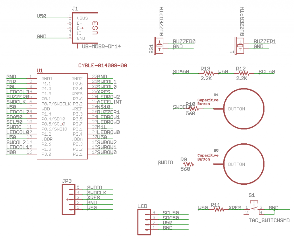
The main page contains the
- PSoCBLE module: Notice that I used every single pin except for VRef. Also notice that I overloaded SWD-Clock and SWD-IO pins by attaching capsense buttons to those pins. This means that I will never be able to debug and use Capsense at the same time.
- USB Connector: When I was trying to figure out how to make the board less expensive my son suggested that everybody has a USB charger, so why don’t you just power the pinball machine with that? I thought that this was a great idea as it eliminates a $5+ wall wart.
- Two buzzers. These are super simple low cost 12mm through hole buzzers which are used by the MusicPlayer component.
- Two capsense buttons multiplexed to the SWDCLK and SWDIO pins of the chip. Notice that they have a 560Ohm series resistor
- The reset button for the system which just pulls down the XRES when you press the button. It also has the 10K pullup resistor which pulls up XRES when the button is not being pressed
- Pull-up resistors for the 5V I2C bus.
- A 5-Pin programming plug for the MiniProg-3 connected to SWDIO and SWDCLK and the Power/Ground
- A plug for the I2C LCD to connect to the I2C Bus
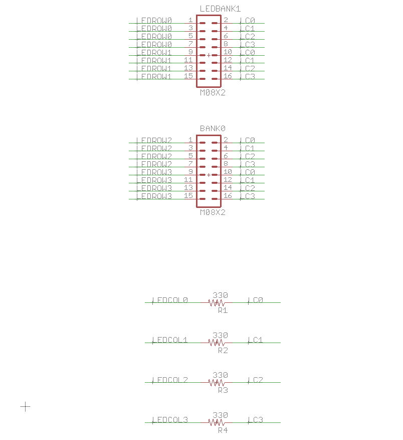
Page two of the schematic contains two connectors for the LEDs which I talked about in detail in the Matrix LED Posts . It also contains the current limiting resistors. In order to save money in the BOM I am not going to actually put connectors into the 100mil center holes, but will let the kids learn to solder by attaching the wires directly into the holes with solder.
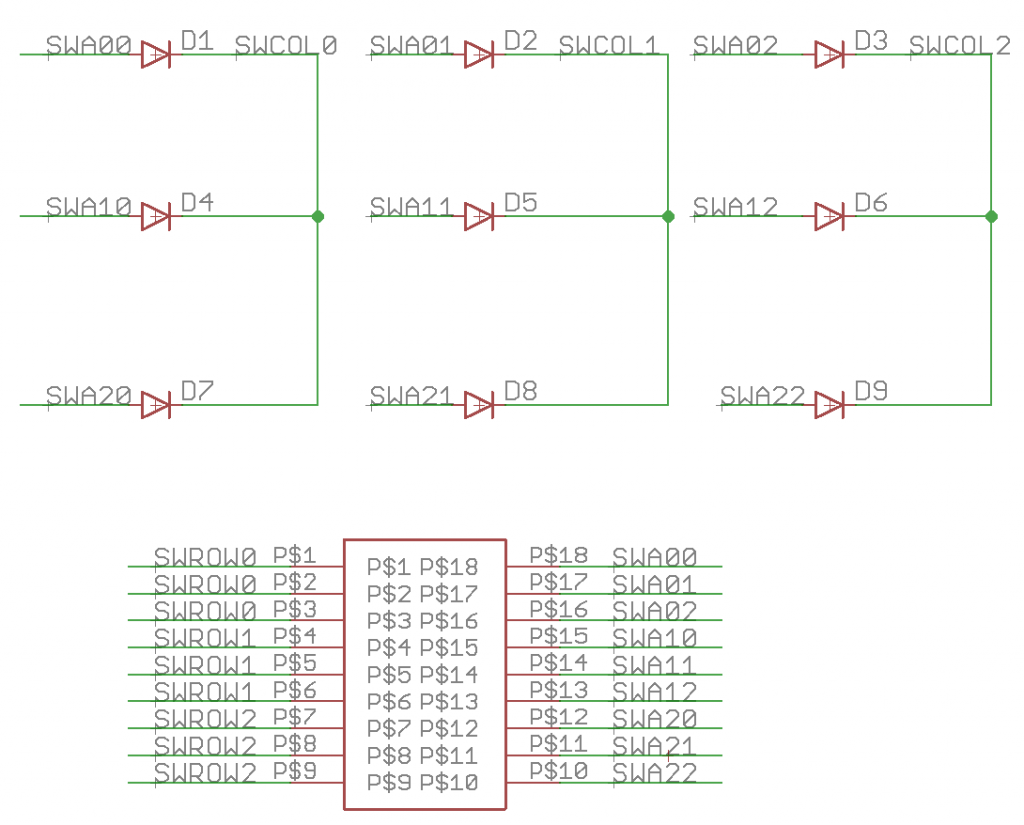
Page three of the schematic contains the switch matrix connectors and diodes.
I thought that it would be a really cool idea to have an accelerometer on the board to provide a tilt functionality. This actually turned out to be a serious PITA because I couldn’t find a cheap accelerometer that was 5v. So, in addition to the accelerometer I have to provide a level translator for the I2C bus (PCA9306) and a level translator for the Accelerometer interrupt line (the mostfet and pull-up resistors). I also have to provide a 3.3v power supply (next page of the schematic)
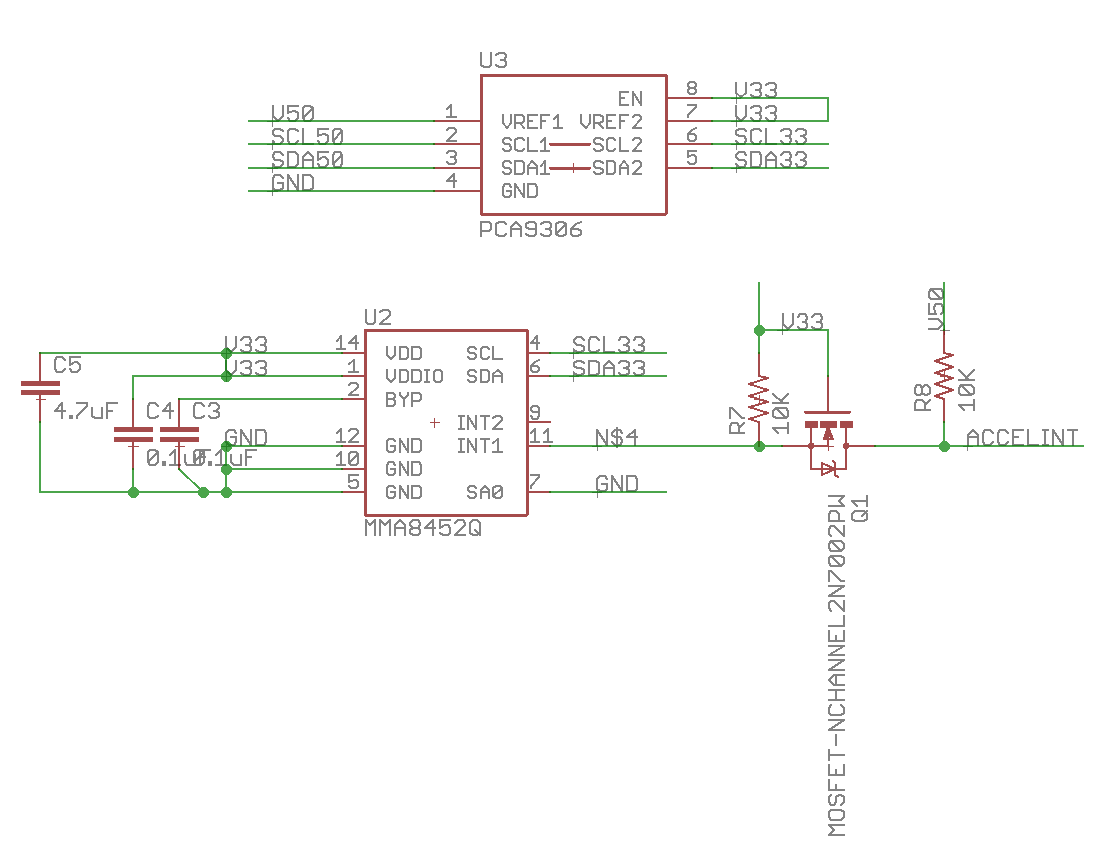
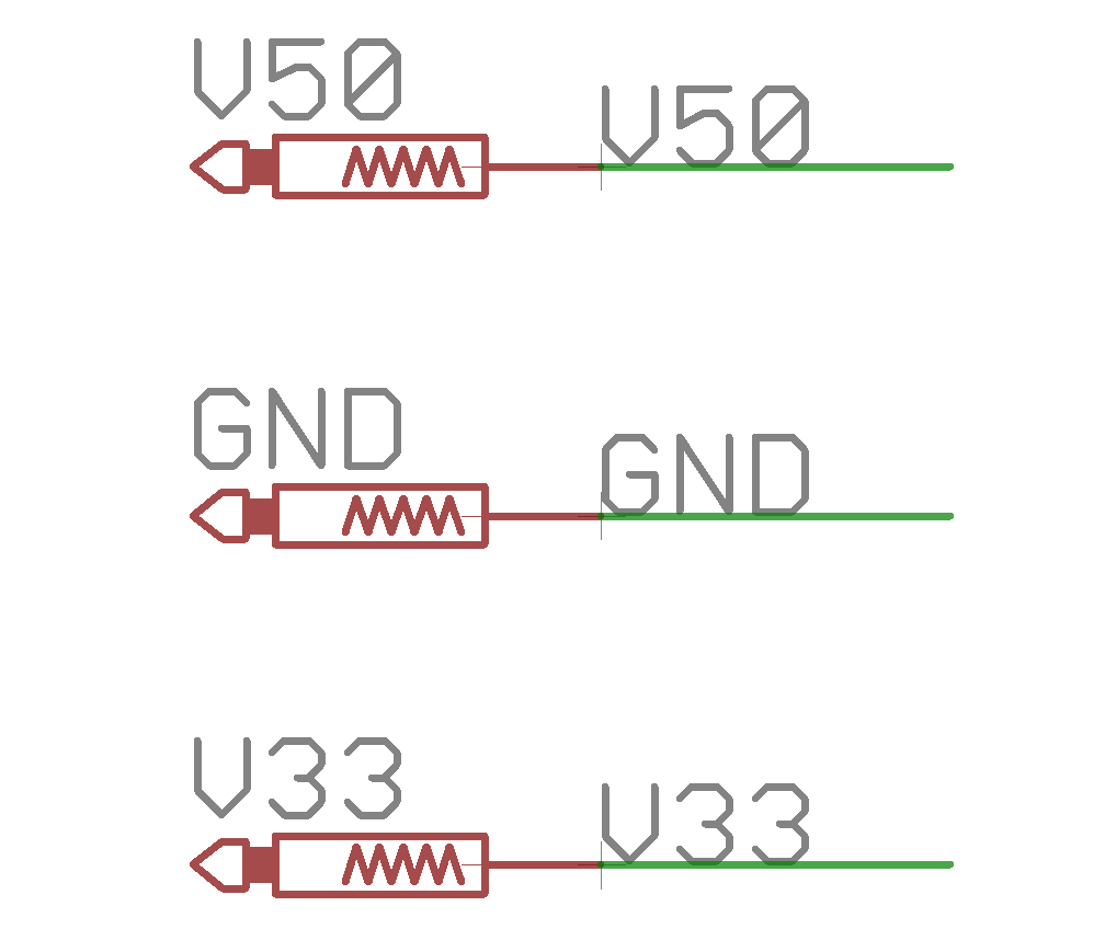
The 3.3v accelerometer requires a 3.3v power supply, so on this page I use an REG317 to create 3.3v from the VBUS power supply.

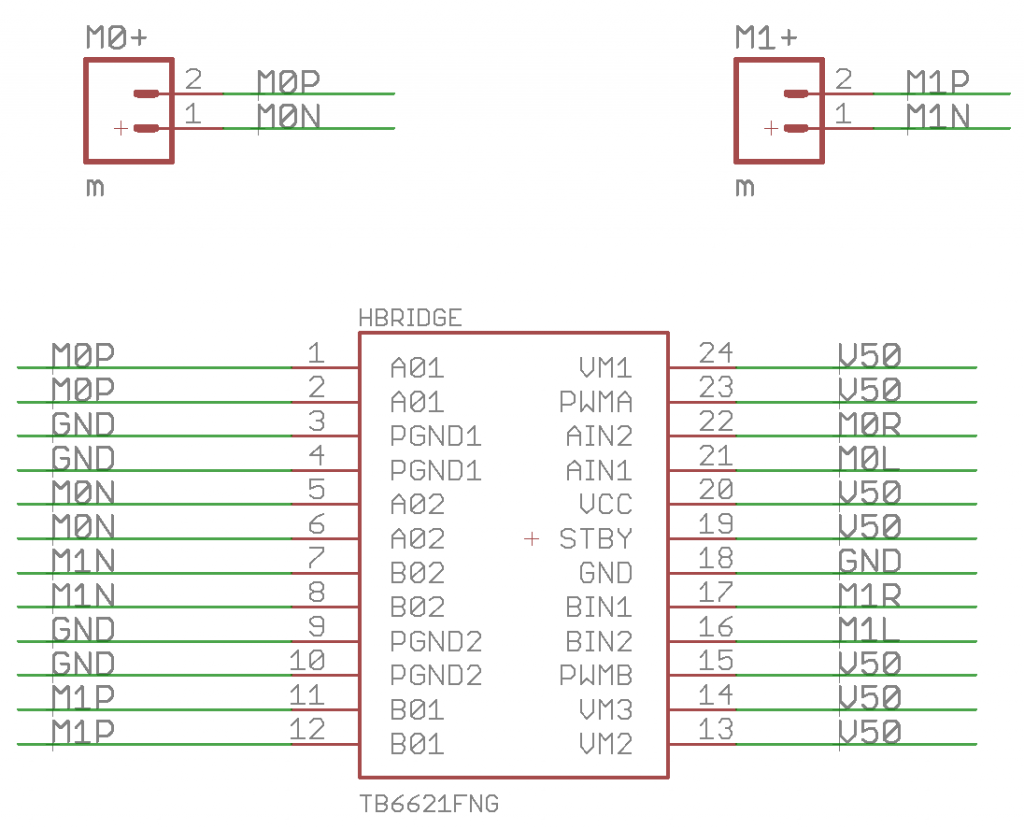
In order to drive the two brushed DC motors I use a TB6621 motor driver chip that contains two H-Bridges.
Finally I like to have test points on the board to measure stuff while I am assembling the board.
In the next post Ill talk about the creation of the layout for the printed circuit board.
You can find all of the source code and files at the IOTEXPERT site on github.
Index
Description
Pinball: Newton's Attic Pinball
An introduction to the project and the goals
Pinball: Lotsa Blinking LEDs
Everyone needs a bunch of LEDs on their Pinball Machine
Pinball: Matrix LEDs (Part 1)
Saving PSoC pins by using a matrix scheme
Pinball: Matrix LEDs (Part 2)
Solving some problems with the matrix
Pinball: Matrix LEDs Component
How to turn the Matrix LED into a component
Pinball: A Switch Matrix
Implementing a bunch of switches
Pinball: Switch Matrix Component (Part 1)
The switch matrix component implementation
Pinball: Switch Matrix Component (Part 2)
The firmware for matrix component
Pinball: Switch Matrix Component (Part 3)
Test firmware for the matrix component
Pinball: The Music Player (Part 1)
The schematic and symbol for a Music Player component
Pinball: The Music Player (Part 2)
The Public API for the Music Player component
Pinball: The Music Player (Part 3)
The firmware to make the sweet sweet music
Pinball: The Music Player (Part 4)
The test program for the music player
Pinball: The Motors + HBridge
Using an Bridge to control DC Motors
Pinball: The Eagle Schematic
All of the circuits into an Eagle schematic
Pinball: The Printed Circuit Board 1.0
The first Eagle PCB layout of the printed circuit board
Pinball: The PCB Version 1.0 Fail
Problems with the first version of the Eagle PCB layout
Pinball: PCB Layout 1.2 Updates using Eagle
Fixing the errors on the first two versions of the Eagle PCB
Pinball: Assemble and Reflow the 1.2 PCB
Assembling the Eagle PCB
Pinball: Testing the Eagle PCB
Firmware to test the newly built Pinball printed circuit board
Pinball: Debugging the Motor Driver
Fixing the motor driver PSoC project
Pinball: Hot-Air Reworking the Accelerometer Solder
Using a Hot-Air Rework tool to reflow a QFN
Pinball: Debugging the LM317 Power Supply- A Tale of Getting Lucky
Debugging the LM317/LM117 power supply
No comment yet, add your voice below!