Summary
In the previous articles I talked about the GE Hackathon, using WICED and CapSense, and finally creating a Particle Photon configuration. In this article I will show you the WICED HTTP Client firmware which will read the button state and send it via WICED HTTP to the Particle Cloud. To build this project I will start from the I2C Read firmware that I talked about in this article.
There are two parts of this application
- The “main” application which reads the buttons and sends a message
- The “sendMessage” function which builds a WICED HTTP message and sends it to the Particle cloud.
Main Application
I took the code from the previous example (CY3280 –> I2C –> WICED) and only made a few modifications (though I rearranged things a bit to make it easier to look at)
- I joined the network (line 126)
- I look up the IP address of the Particle Cloud (line 128)
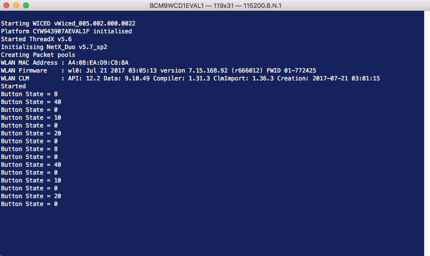
- Then I send a HIGH or LOW via the sendMessage function based on the state of the buttons (all the buttons do the same thing)
#include "wiced.h"
#include <stdlib.h>
#define I2C_ADDRESS (0x37)
#define BUTTON_REG (0xAA)
wiced_semaphore_t buttonPress; // used to signal in ISR to signal main
void application_start( )
{
wiced_init(); // Initialize the WICED device
wiced_rtos_init_semaphore(&requestSemaphore); // Initialize
wiced_result_t result;
wiced_network_up(WICED_STA_INTERFACE, WICED_USE_EXTERNAL_DHCP_SERVER, NULL);
wiced_hostname_lookup( SERVER_HOST, &ip_address, DNS_TIMEOUT_MS, WICED_STA_INTERFACE );
wiced_rtos_init_semaphore(&buttonPress);
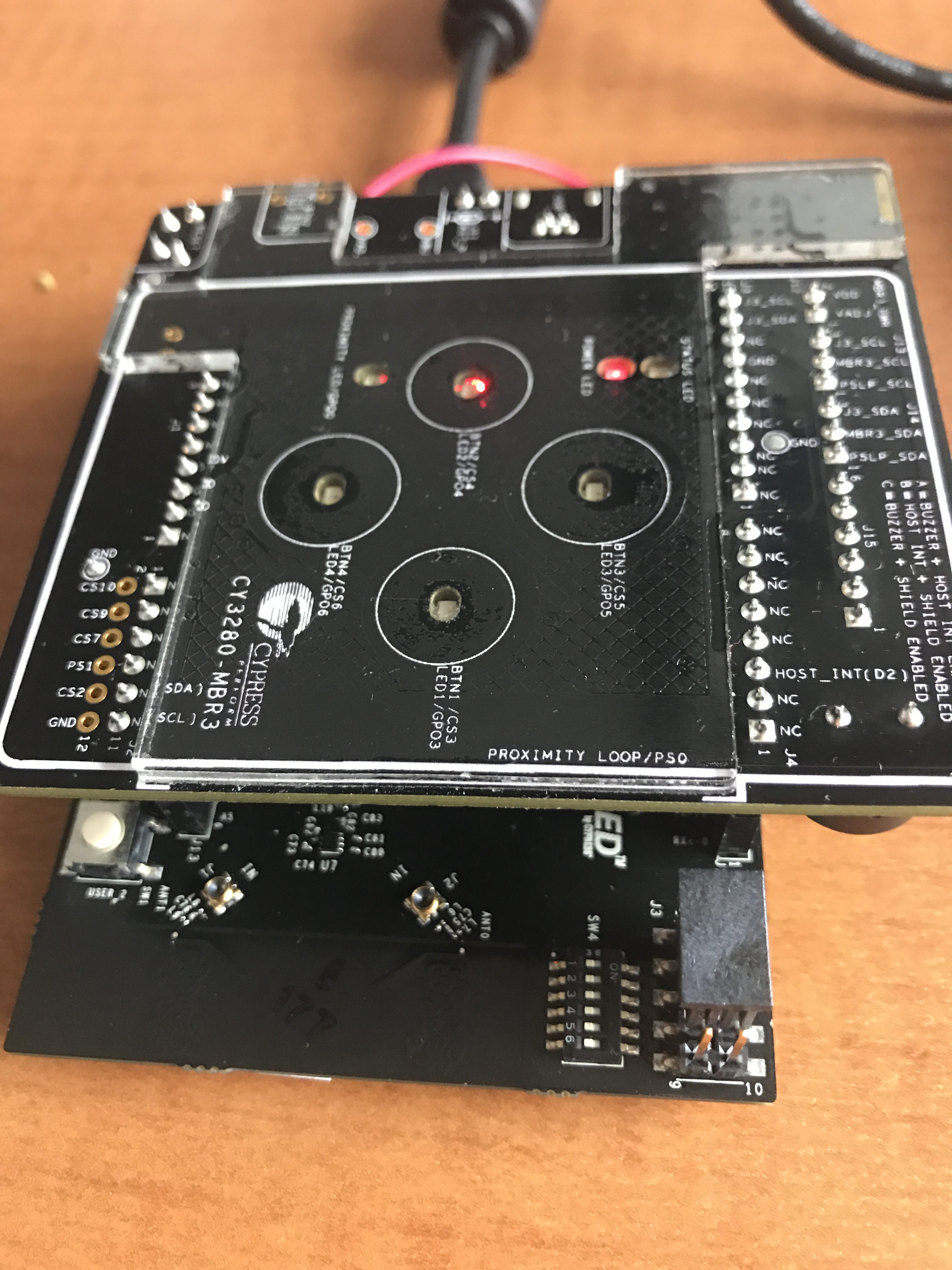
// WICED_GPIO_9 is the MBR3 Interrupt Pin
wiced_gpio_init(WICED_GPIO_9,INPUT_PULL_UP);
wiced_gpio_input_irq_enable(WICED_GPIO_9, IRQ_TRIGGER_FALLING_EDGE, button_isr, NULL); /* Setup interrupt */
/* Setup I2C master */
const wiced_i2c_device_t i2cDevice = {
.port = WICED_I2C_2,
.address = I2C_ADDRESS,
.address_width = I2C_ADDRESS_WIDTH_7BIT,
.speed_mode = I2C_STANDARD_SPEED_MODE
};
wiced_i2c_init(&i2cDevice);
/* Tx buffer is used to set the offset */
uint8_t tx_buffer[] = {BUTTON_REG};
uint8_t buttonStatus;
while ( 1 )
{
wiced_rtos_get_semaphore(&buttonPress,WICED_WAIT_FOREVER);
// Do this until the MBR3 is alive. It goes into deep sleep and wakes when you
// send the first command.
do {
result = wiced_i2c_write(&i2cDevice, WICED_I2C_START_FLAG | WICED_I2C_STOP_FLAG, tx_buffer, sizeof(tx_buffer));
}
while(result != WICED_SUCCESS);
result=wiced_i2c_read(&i2cDevice, WICED_I2C_START_FLAG | WICED_I2C_STOP_FLAG, &buttonStatus, sizeof(buttonStatus));
if(buttonStatus > 0)
{
WPRINT_APP_INFO(("Sending On\n"));
sendMessage("HIGH");
}
else
{
WPRINT_APP_INFO(("Sending Off\n"));
sendMessage("LOW");
}
}
}
Send Message via WICED HTTP
The WICED HTTP sendMessage function simply
- Creates a http_client (which is just a mechanism to keep track of an HTTP connection
- Sets up a connection (lines 77-80)
- Makes the connection (line 82)
- Creates the message (line 88) in “application/x-www-form-urlencoded” format
- Builds the HTTP headers for a HTTP “POST” (lines 90-105)
- Write the Request (lines 108 –> 112)
- Waits for the response using semaphore (line 114)
- Destroys the connection (line 115 –> 116)
#include "wiced_tls.h"
#include "http_client.h"
#define SERVER_PORT ( 443 )
#define SERVER_HOST "api.particle.io"
#define SERVER_RESOURCE "/v1/devices/2a001b000347353137323334/digitalwrite"
#define PARTICLE_ACCESS_TOKEN "1311f9217a60"
#define DNS_TIMEOUT_MS ( 10000 )
#define CONNECT_TIMEOUT_MS ( 3000 )
wiced_semaphore_t requestSemaphore; // used to signal request is done static http_client_t client;
static http_request_t request;
static http_client_configuration_info_t client_configuration;
static wiced_ip_address_t ip_address;
/* void sendMessage - Send HTTP request to turn on or off the LED
*/
void sendMessage( char *state )
{
http_client_init( &client, WICED_STA_INTERFACE, event_handler, NULL );
/* configure HTTP client parameters */
client_configuration.flag = (http_client_configuration_flags_t)(HTTP_CLIENT_CONFIG_FLAG_SERVER_NAME | HTTP_CLIENT_CONFIG_FLAG_MAX_FRAGMENT_LEN);
client_configuration.server_name = (uint8_t*)SERVER_HOST;
client_configuration.max_fragment_length = TLS_FRAGMENT_LENGTH_1024;
http_client_configure(&client, &client_configuration);
http_client_connect( &client, (const wiced_ip_address_t*)&ip_address, SERVER_PORT, HTTP_USE_TLS, CONNECT_TIMEOUT_MS );
http_header_field_t header[3]; // Three headers
char messageBody[128]; // Enough to hold the message body
char messageLengthBuffer[10]; // Enough to hold the characters for the Content-Length: header
sprintf(messageBody,"access_token=%s¶ms=D7%%2C%s",PARTICLE_ACCESS_TOKEN,state);
header[0].field = HTTP_HEADER_HOST;
header[0].field_length = sizeof( HTTP_HEADER_HOST ) - 1;
header[0].value = SERVER_HOST;
header[0].value_length = sizeof( SERVER_HOST ) - 1;
#define MIME_FORM_URL "application/x-www-form-urlencoded"
header[1].field = HTTP_HEADER_CONTENT_TYPE;
header[1].field_length = sizeof( HTTP_HEADER_CONTENT_TYPE ) - 1;
header[1].value = MIME_FORM_URL;
header[1].value_length = sizeof( MIME_FORM_URL ) - 1;
sprintf(messageLengthBuffer," %d",strlen(messageBody)); // Put the message body into the buffer so that you can strlen it
header[2].field = HTTP_HEADER_CONTENT_LENGTH;
header[2].field_length = sizeof( HTTP_HEADER_CONTENT_LENGTH ) - 1;
header[2].value = messageLengthBuffer;
header[2].value_length = strlen(messageLengthBuffer);
// Build the HTTP Message
http_request_init( &request, &client, HTTP_POST, SERVER_RESOURCE, HTTP_1_1 );
http_request_write_header( &request, &header[0], 3 ); // 3 headers
http_request_write_end_header( &request );
http_request_write(&request,(uint8_t*)messageBody,strlen(messageBody));
http_request_flush( &request );
wiced_rtos_get_semaphore(&requestSemaphore,10000); // wait up to 10 seconds to close the request and the client
http_request_deinit(&request);
http_client_deinit(&client);
}
WICED HTTP Event Handler
The way that the WICED HTTP executes is that it has a worker thread waiting on the TCP socket. When it gets a response it runs your callback function and tells you what happened. In this case I just tell my thread to close the connection and move on.
/*
 * void event_handler() is called by the http_client function when
 *  Data is received from the server
 *  a connection is made
 *  a disconnect occurs
 *
 *  When data is received I assume that the response is good and I reset the semaphore so that another request can happen
 */

static void event_handler( http_client_t* client, http_event_t event, http_response_t* response )
{
    switch( event )
    {
        case HTTP_CONNECTED: // Dont do anything
        break;

        case HTTP_DISCONNECTED: // Disconnect if you get this event
            wiced_rtos_set_semaphore(&requestSemaphore);
        break;

        case HTTP_DATA_RECEIVED: // Disconnect if you get this event
            wiced_rtos_set_semaphore(&requestSemaphore);
        break;

        default:
        break;
    }
}