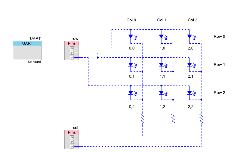
In the previous post I talked in detail about driving LEDs using the PSoC4 BLE GPIOs. The basic problem that I have now is that I want to drive way more LEDs than I have available GPIO pins. Using one GPIO per LED means that I am only able to drive 8 LEDs with the 8 pins that I have reserved. But I want to do 16 not 8. So now what? To solve this, I configure the LEDs into the Matrix. In the schematic below you can see an example 3×3 test matrix. It uses 6 pins and is able to drive 9 LEDs.
So how does it work? Simple. Write a 1 onto the row you want to enable then write a 0 onto the other rows. Next write a 0 onto the column you want to enable and a 1 onto the other columns. For example, if I drive 010 onto the “row” pins and 101 onto the column pins then the LED I have labeled 1,1 will turn on. With this scheme the row pins are used to drive the “power” and the column pins are used to drive the “ground”.
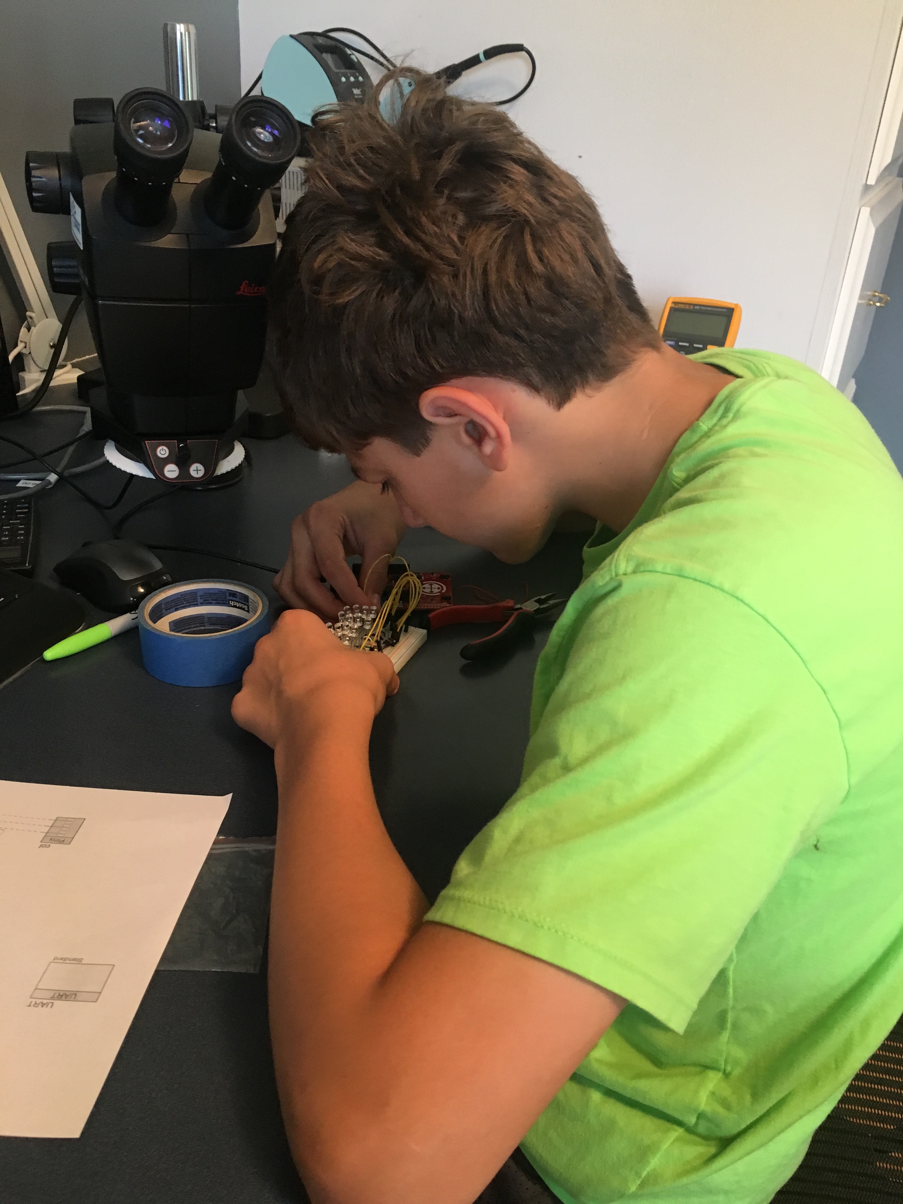
Then I get the lab assistant a.k.a. 12 year old son Nicholas to build up a test board.
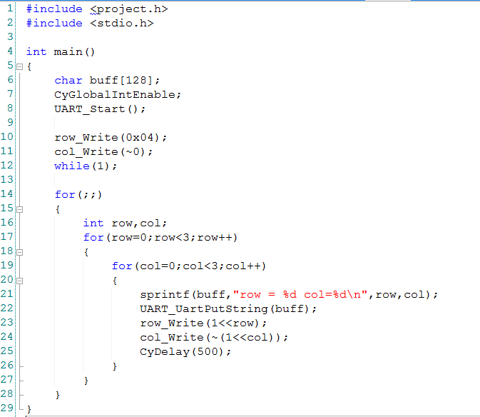
I need a little bit of firmware to turn on each LED one by one.
- Lines 17-19: iterate through the three rows/columns
- Line 23: write the correct pattern to the row driver (001,010,100)
- Line 21-22: print the current row column to the UART
- Line 24: write the correct pattern to the column driver (110,101,011)
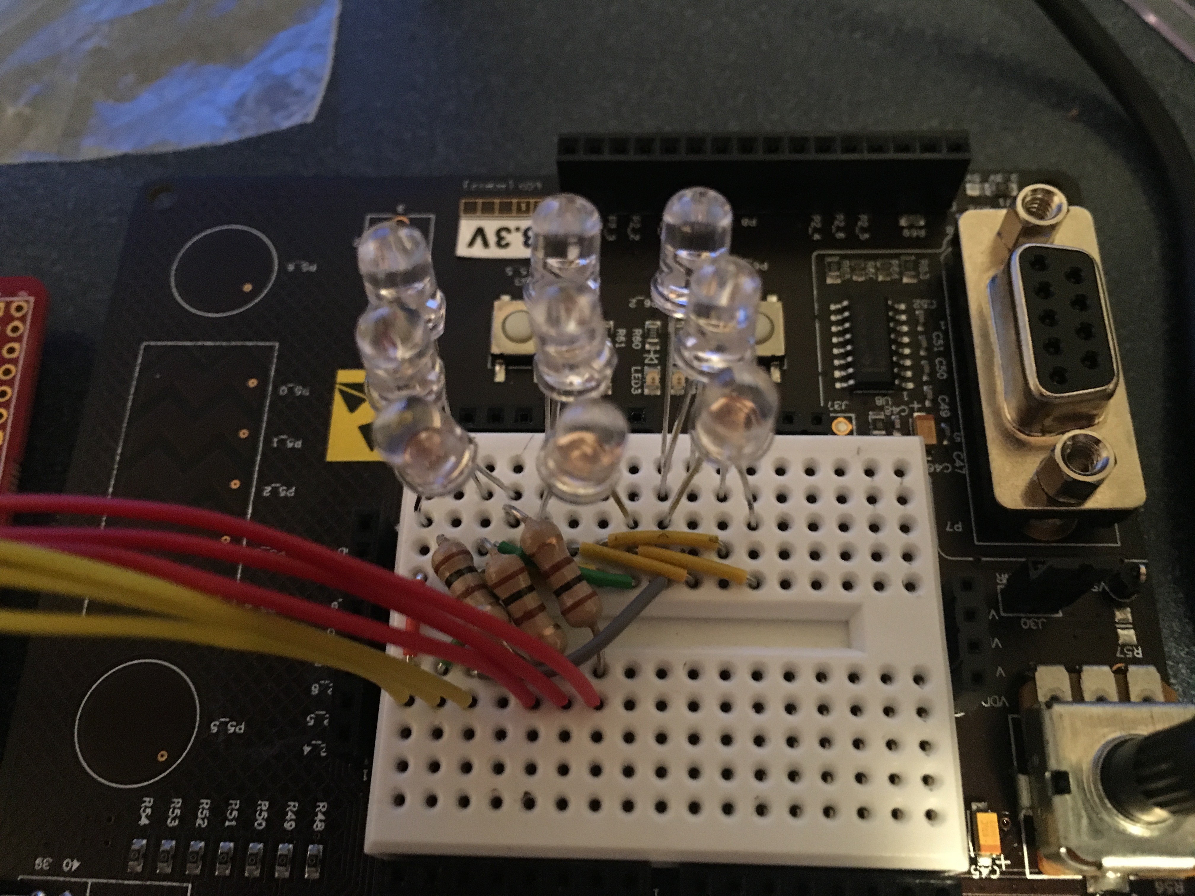
After that everything seems to work… you can see how bright the LEDs are in the movie below.
In the next post I will show you how to Time Division Multiplex the LEDs and explain what the problem is with that scheme.
You can find all of the source code and files at the IOTEXPERT site on github.
Index
Description
Pinball: Newton's Attic Pinball
An introduction to the project and the goals
Pinball: Lotsa Blinking LEDs
Everyone needs a bunch of LEDs on their Pinball Machine
Pinball: Matrix LEDs (Part 1)
Saving PSoC pins by using a matrix scheme
Pinball: Matrix LEDs (Part 2)
Solving some problems with the matrix
Pinball: Matrix LEDs Component
How to turn the Matrix LED into a component
Pinball: A Switch Matrix
Implementing a bunch of switches
Pinball: Switch Matrix Component (Part 1)
The switch matrix component implementation
Pinball: Switch Matrix Component (Part 2)
The firmware for matrix component
Pinball: Switch Matrix Component (Part 3)
Test firmware for the matrix component
Pinball: The Music Player (Part 1)
The schematic and symbol for a Music Player component
Pinball: The Music Player (Part 2)
The Public API for the Music Player component
Pinball: The Music Player (Part 3)
The firmware to make the sweet sweet music
Pinball: The Music Player (Part 4)
The test program for the music player
Pinball: The Motors + HBridge
Using an Bridge to control DC Motors
Pinball: The Eagle Schematic
All of the circuits into an Eagle schematic
Pinball: The Printed Circuit Board 1.0
The first Eagle PCB layout of the printed circuit board
Pinball: The PCB Version 1.0 Fail
Problems with the first version of the Eagle PCB layout
Pinball: PCB Layout 1.2 Updates using Eagle
Fixing the errors on the first two versions of the Eagle PCB
Pinball: Assemble and Reflow the 1.2 PCB
Assembling the Eagle PCB
Pinball: Testing the Eagle PCB
Firmware to test the newly built Pinball printed circuit board
Pinball: Debugging the Motor Driver
Fixing the motor driver PSoC project
Pinball: Hot-Air Reworking the Accelerometer Solder
Using a Hot-Air Rework tool to reflow a QFN
Pinball: Debugging the LM317 Power Supply- A Tale of Getting Lucky
Debugging the LM317/LM117 power supply
No comment yet, add your voice below!