
PSoC 6 Introduction
#
Title
Comment
0
A Two Hour PSoC 6 Class
An introduction to the PSoC 6 class with links to all of the documents
1
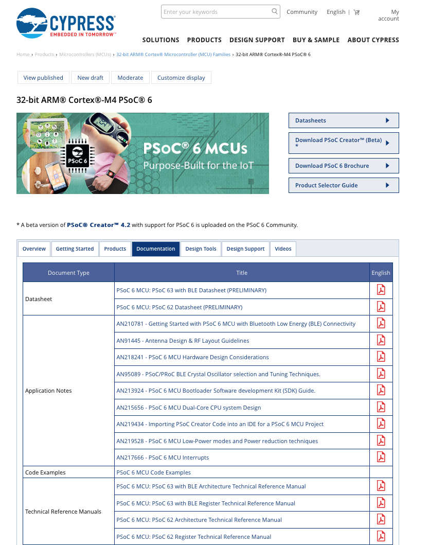
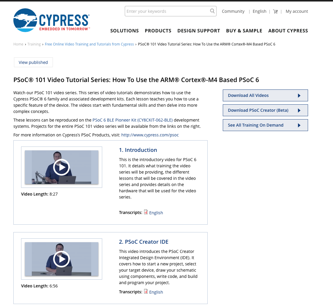
Resources
Links to all of the Cypress PSoC 6 information including videos, application notes etc.
2
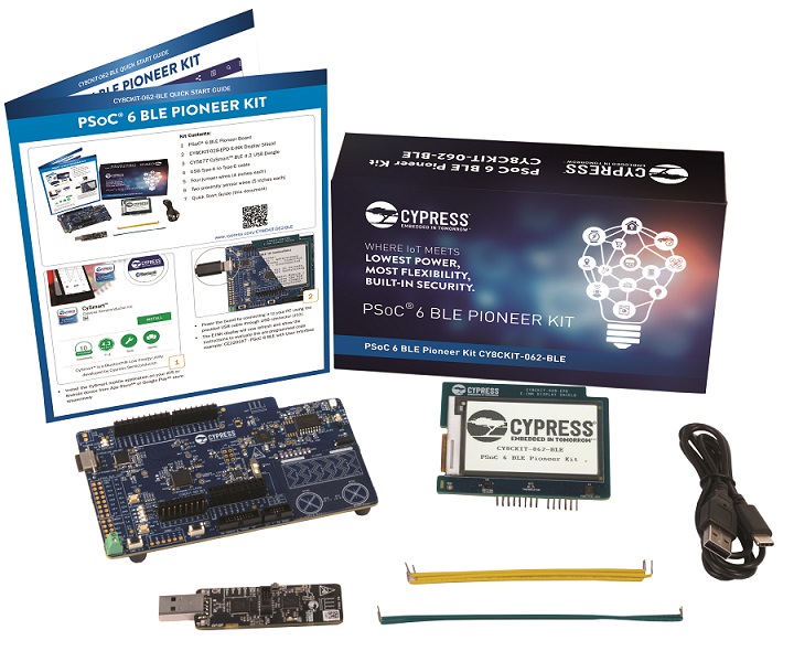
Your First Project
Learn how to build a PSoC 6 project and program your CY8CKIT-062-BLE development kit
3
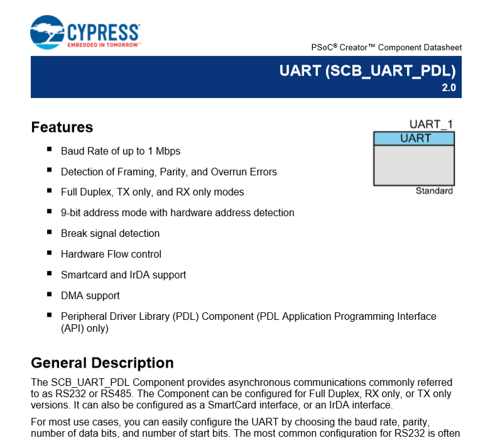
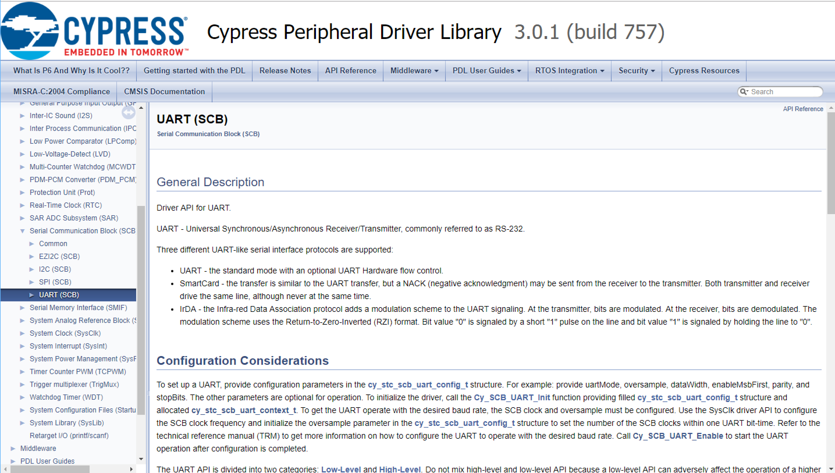
FreeRTOS and a Debugging UART
Build a project using FreeRTOS including a debug console with the UART
4
CapSense
Build a project using the Mutual Cap Buttons and Self Cap Slider
5
Bluetooth Low Energy
Build a CapSense project using BLE and CySmart
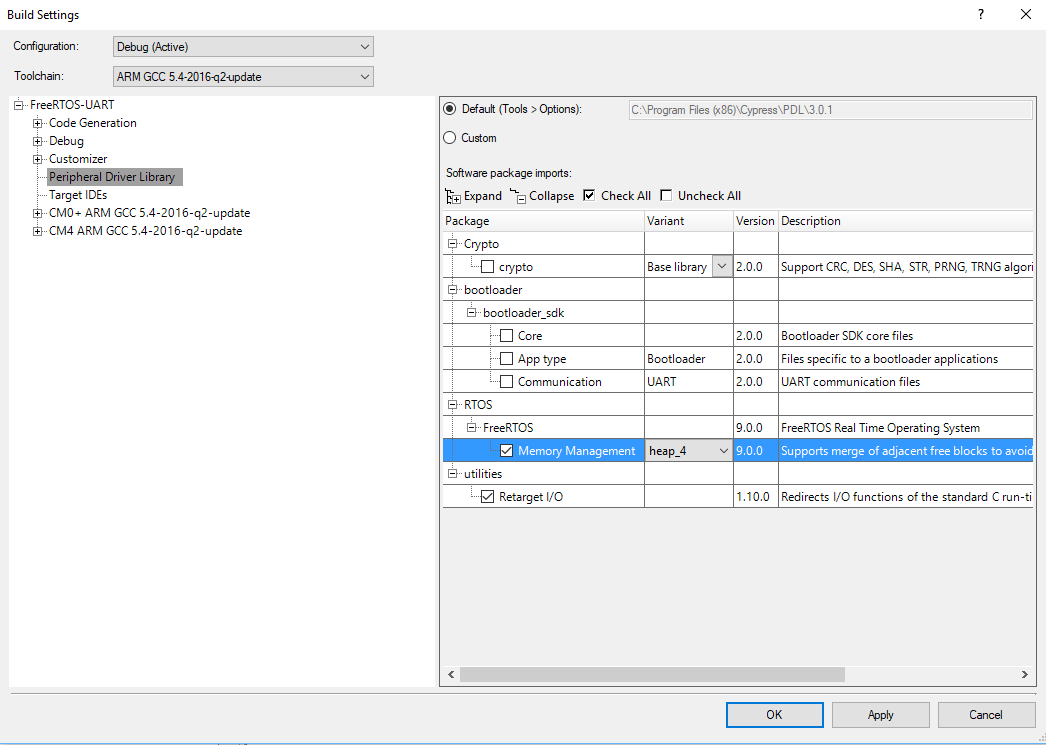
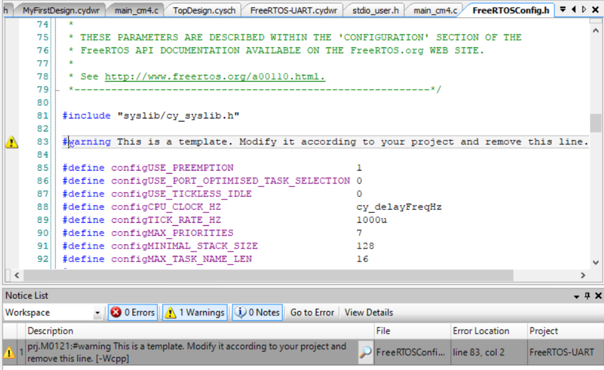
Since I did the webinar several things have happened
- Lesson 4: I fixed an error in the stack size for FreeRTOS
- Lesson 5: The PSoC Creator BLE PDL has been upgraded to greatly simplify the notifyCapSense function
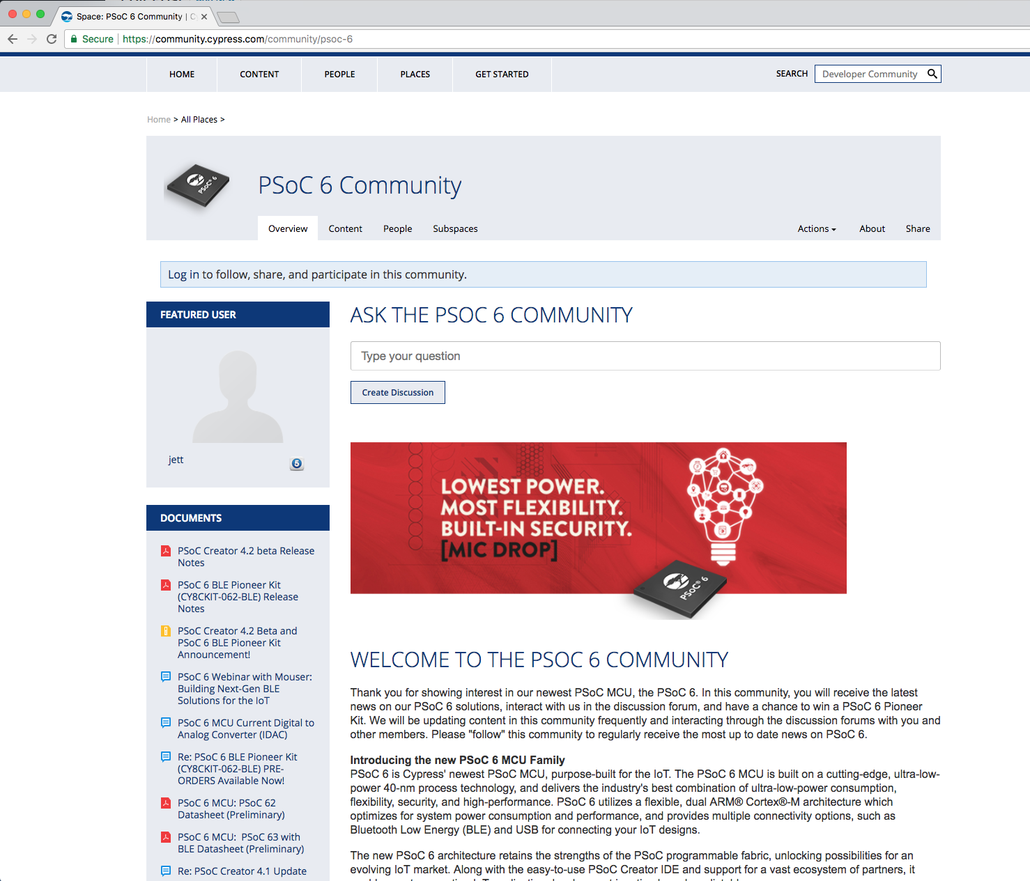
All of the projects are available at git@github.com:iotexpert/psoc-6-introduction.git or www.github.com/iotexpert/psoc-6-introduction
Project Description
This project is a PSoC 6 BLE extension of the previous project with CapSense and UART.
The BLE will:
- Advertise the device with the name “P6Intro” and as having the CapSense Service
- Will allow one connection (with no security)
- A BLE CapSense Service with the CapSense Slider characteristic as “notify”
- When the CapSense slider updates it will send a notification to any connected device
The CapSense will (same as before)
- BTN0 will set the intensity to 0%
- BTN1 will set the intensity to 100%
- CapSense slider will set the intensity (0-100) when touched
The UART will (same as before)
- UART Key ‘0’ turn the LED to intensity = 0%
- UART Key ‘1’ turn the LED to intensity = 100%
- UART Key ‘5’ turn the LED to intensity = 50%
- UART Key ‘?’ will printout help
How does it work?
This device will act as a GAP Peripheral with a GATT database server with the CapSense Service. The PSoC 6 BLE component will allow you to split the BLE function onto the CM0+ (Controller) and the CM4 (Host and Profiles). On the CM4 you will build an event handler which will act each time something happens in the Bluetooth world e.g. a connection, a disconnection, a read or write.
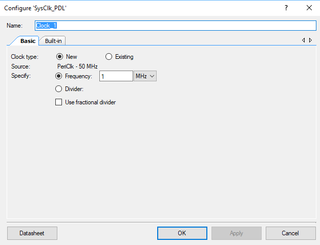
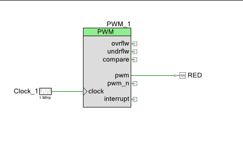
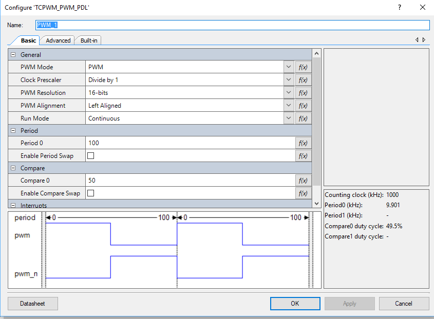
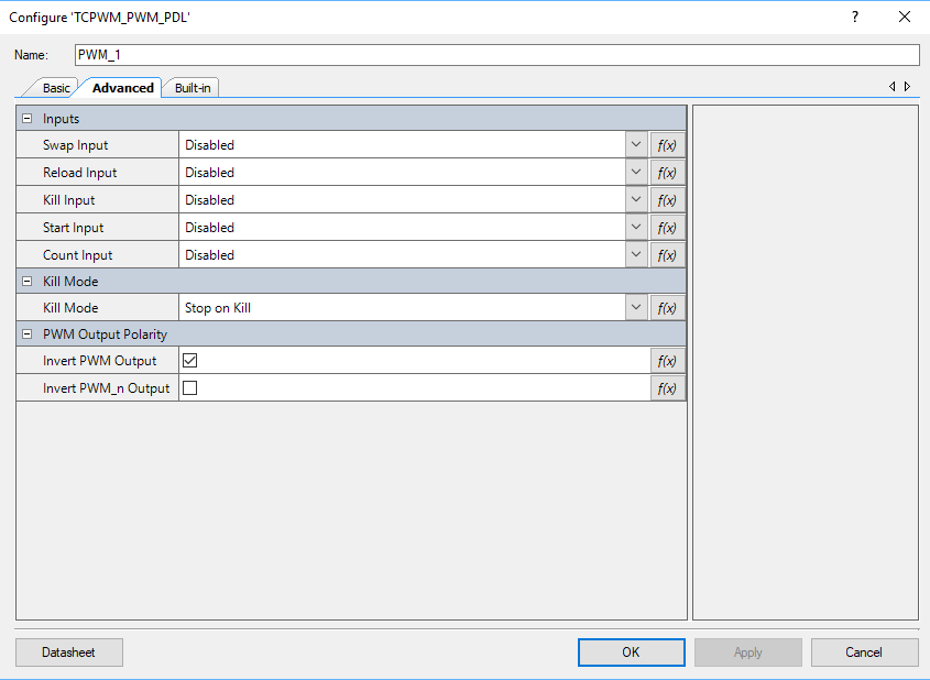
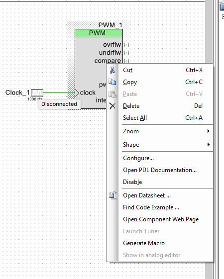
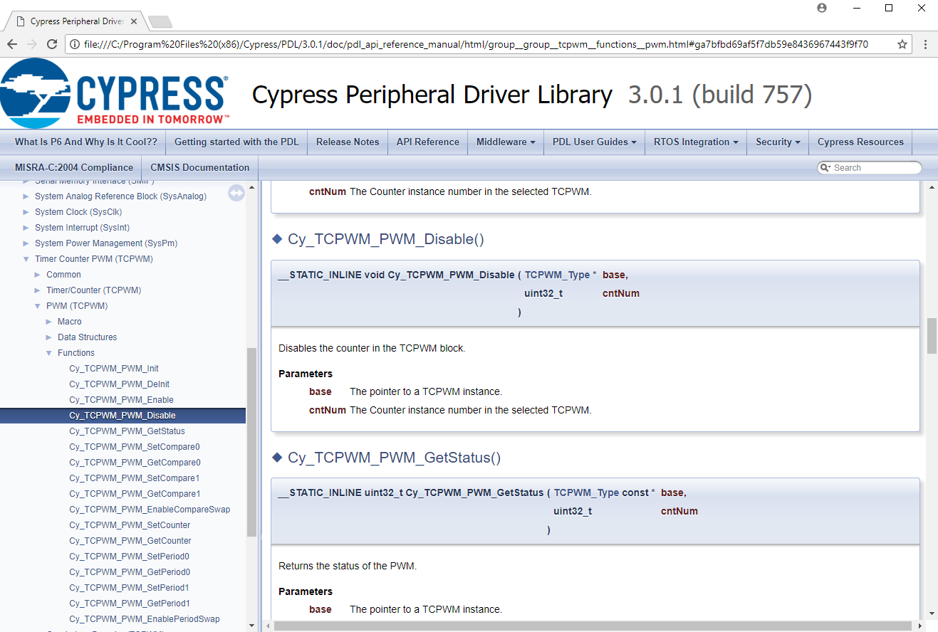
(same as previous project) You can control the intensity of an LED with a pulse width modulator and a high frequency input clock. If the duty cycle is “small” then the intensity of the LED is low (meaning dim). If the duty cycle is “big” then the intensity is “high”. A 0% duty cycle will be off, a 50% duty cycle will be in the middle and 100% duty cycle will be all on. To make this work I will set the input clock to 1 MHZ and the PWM Period to 100. The PWM Compare value will then be set between 0 and 100 to represent brightness in percent.
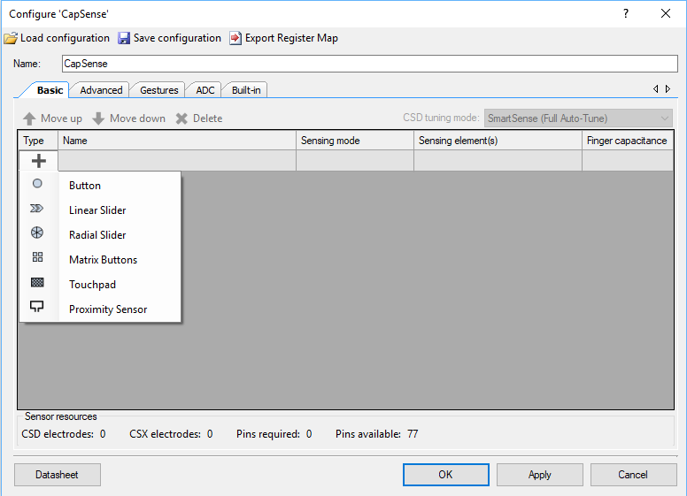
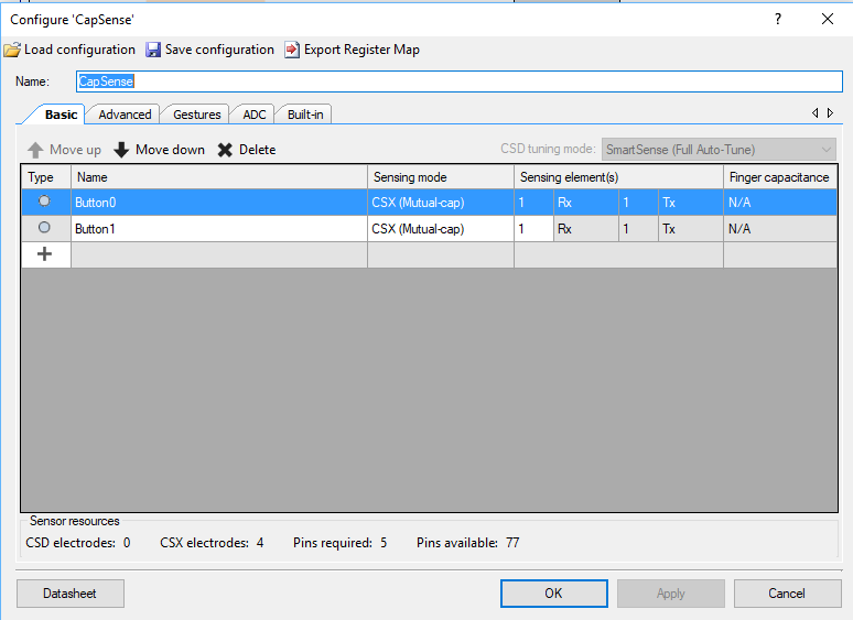
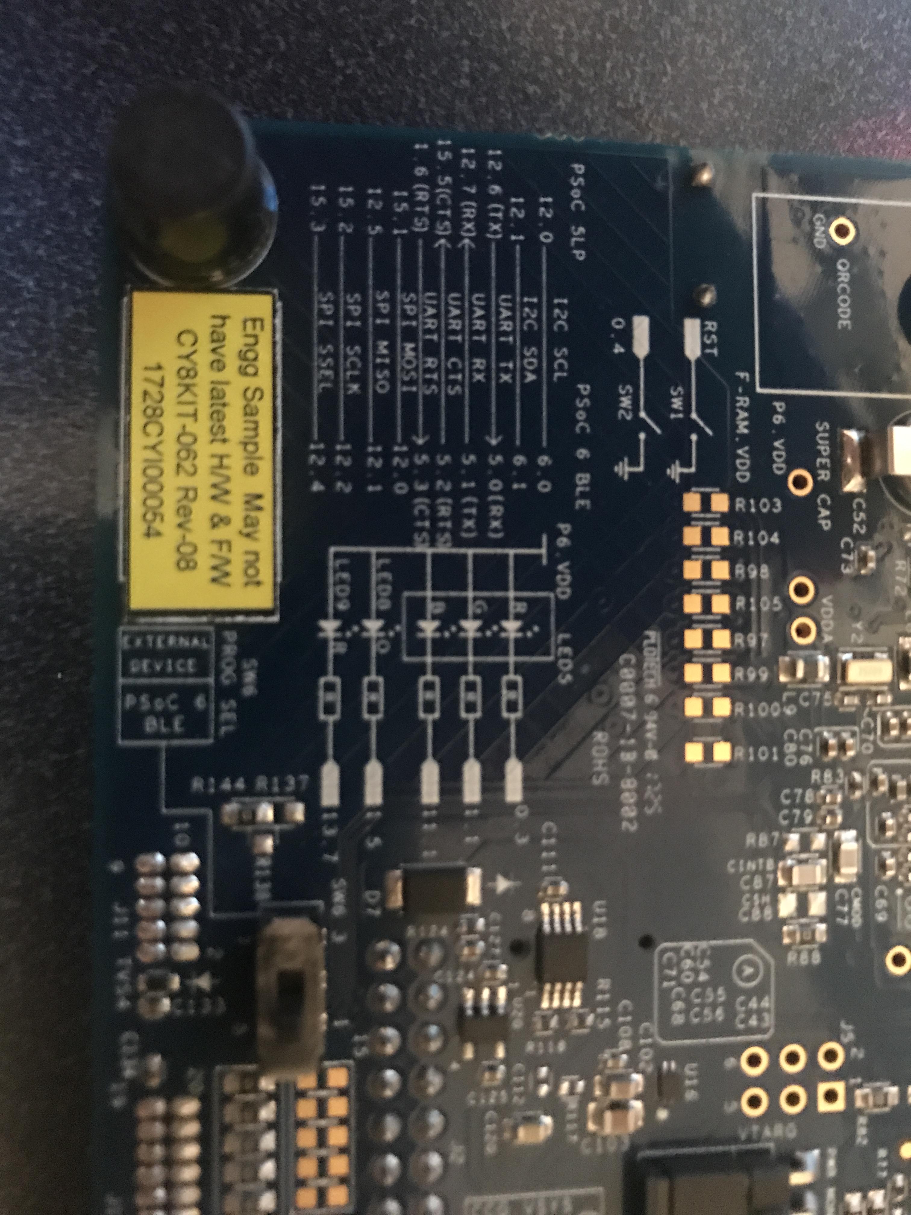
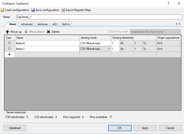
(same as previous project) The Cypress CapSense block has two sensing modes, mutual capacitance and self-capacitance. The CY8CKIT-062-BLE has two Mutual Capacitance buttons and a 5-Segment Self or Mutual Capacitance Slider.
The project will have four tasks
- BLE – Will act as a BLE GATT Peripheral that advertises the CapSense Service with the CapSense Slider. The value of the slider will ‘Notify’
- UART – Read data from the keyboard and send messages to the PWM Task
- CapSense – Read finger positions from the slider and buttons and send messages to the PWM Task
- PWM – Will have an input queue, when a integer message is received it will set the PWM compare value to the integer received (0 >= msg <= 100)
How am I going to do it?
- Copy, Paste and Rename the CapSense UART Project
- Add and Configure the BLE Component
- Fix the Interrupts
- Update the main_cm0p. c to run the BLE radio
- Add three global variables to main_cm4.c
- Create a new task to process the BLE
- Create an Event Handler
- Make a Function to Send Notifications
- Update the capSenseTask to Send Values
- Add the bleTask to main function in main_cm4.c
- Program and Test
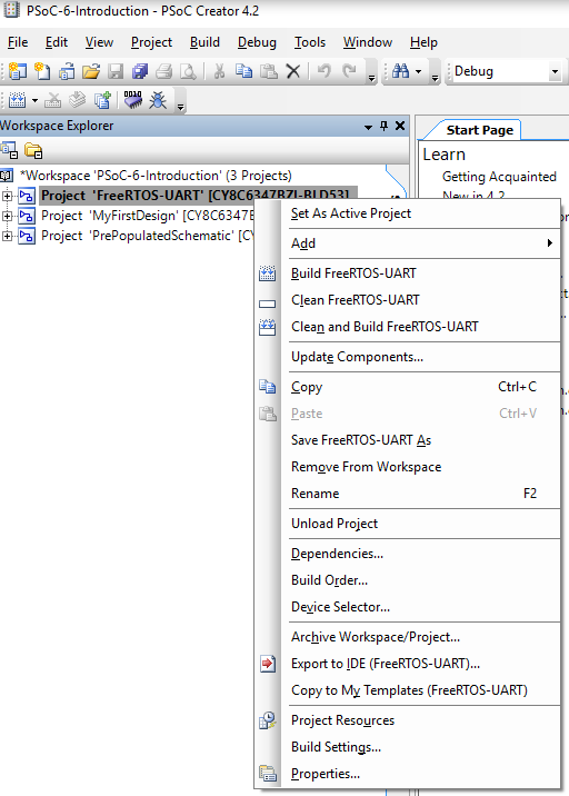
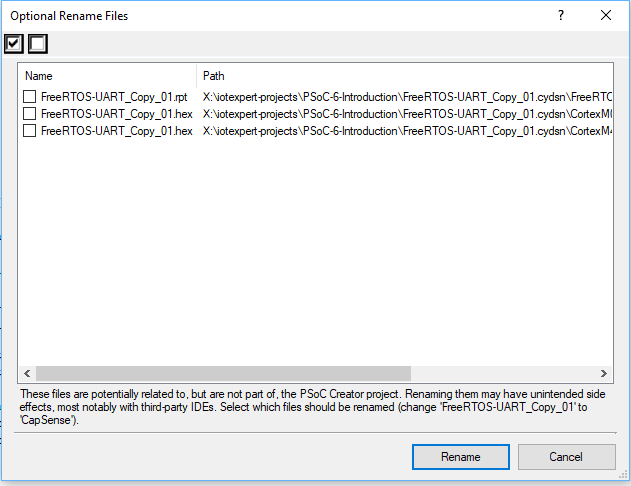
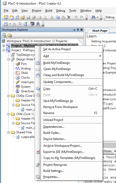
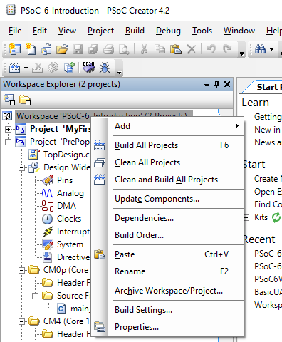
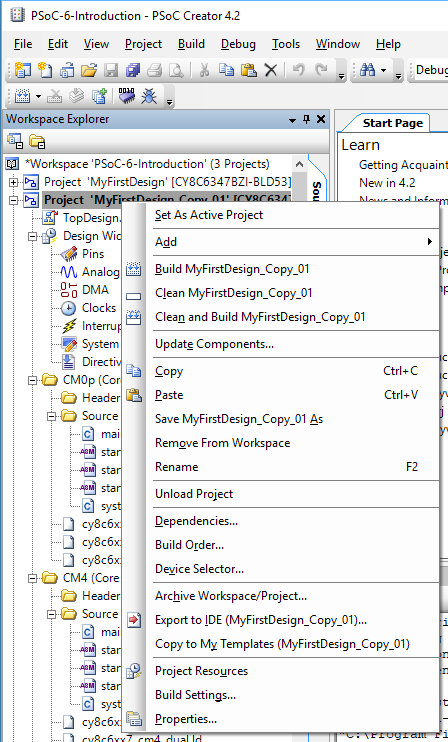
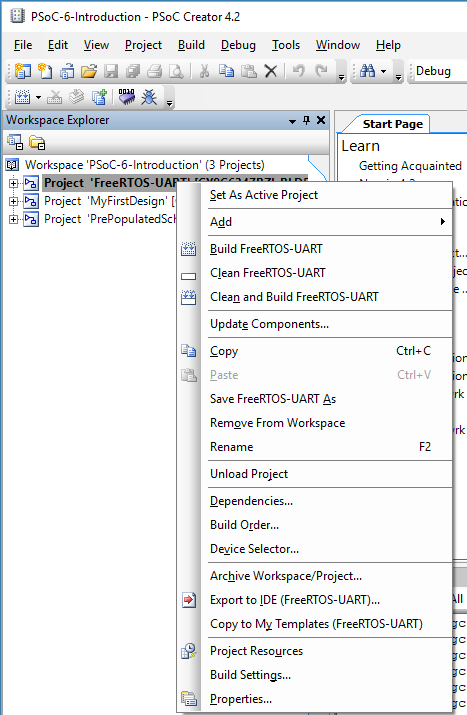
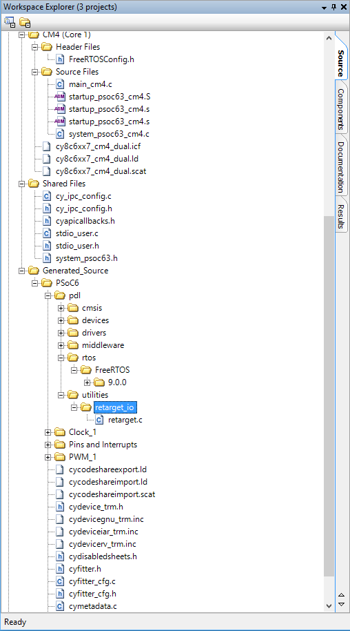
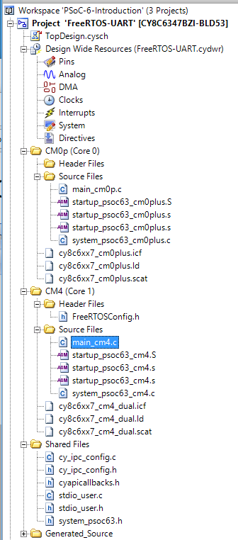
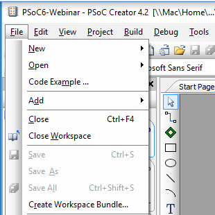
Copy, Paste and Rename the CapSense UART Project
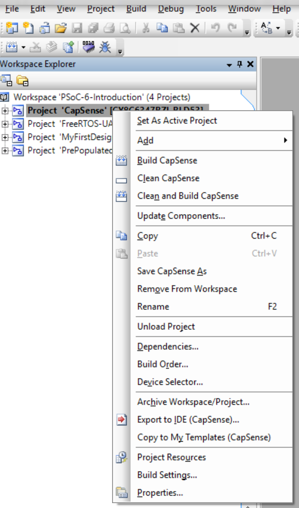
Right click on the PSoC-6-Introdution and Paste

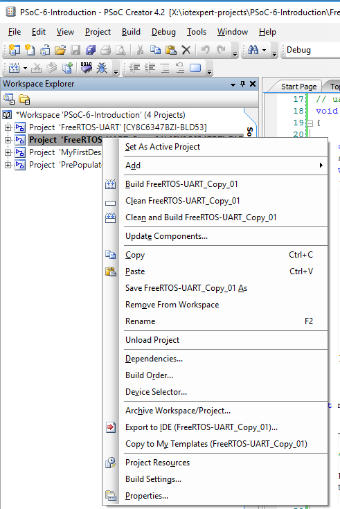
Right click and rename the project to be CapSense_BLE
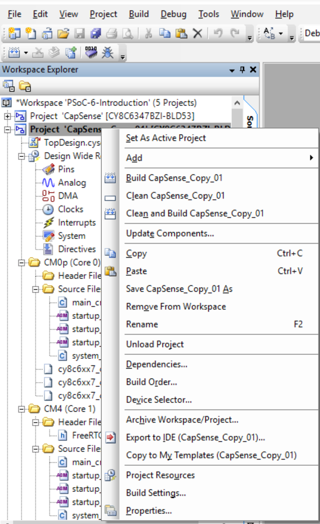
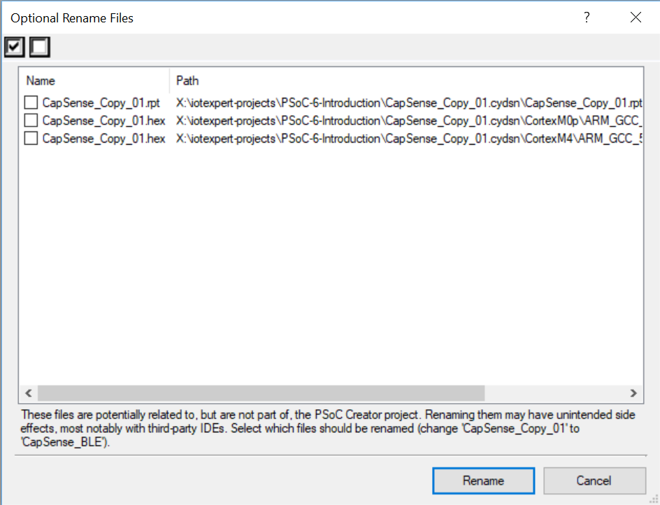
When is asks you to rename… do it
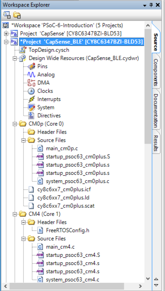
It should look like this now.
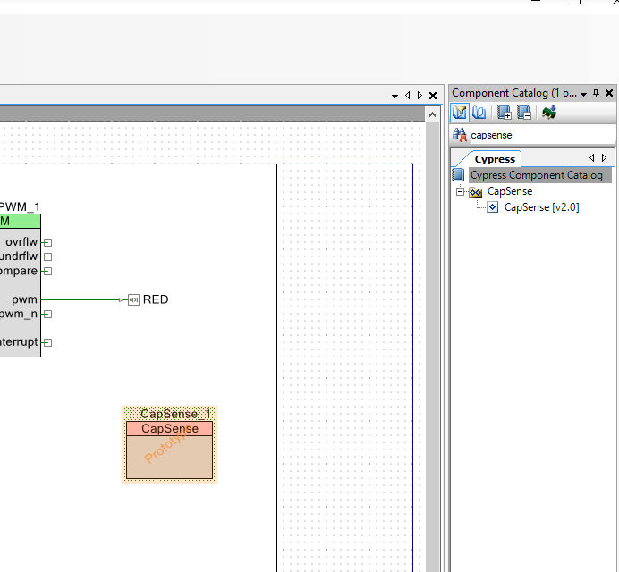
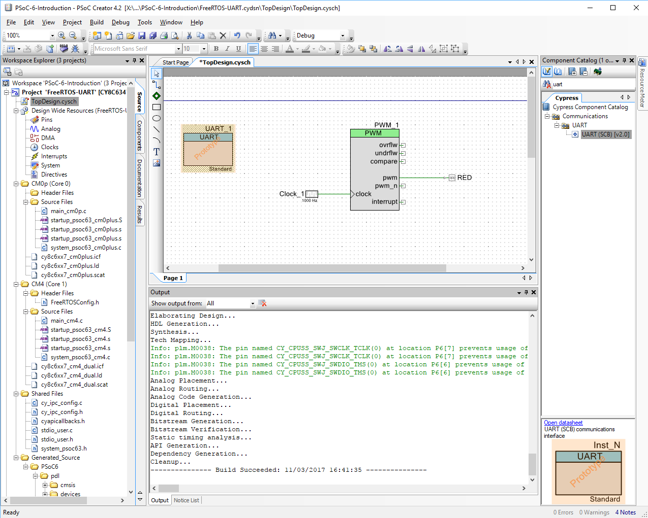
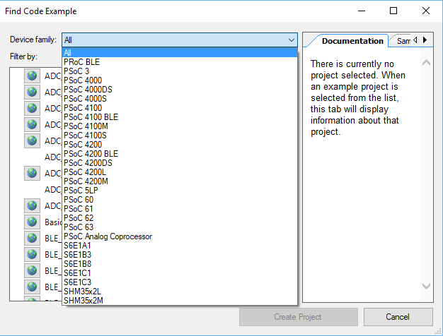
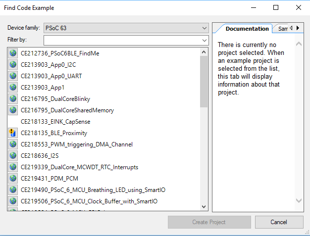
Add and Configure the BLE Component
Go to the Component Catalog and find the Bluetooth Low Energy component and drag/drop it into your design schematic.
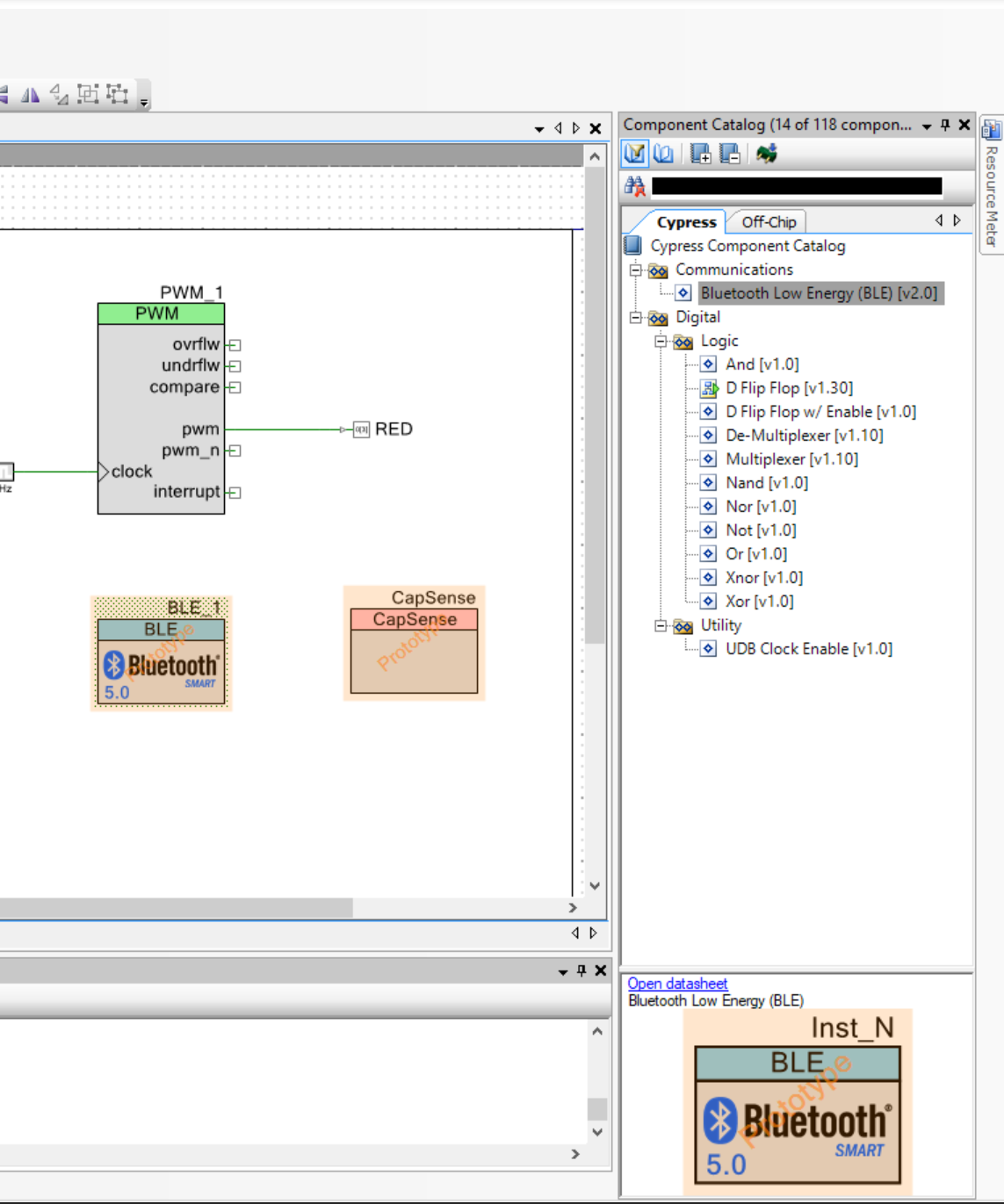
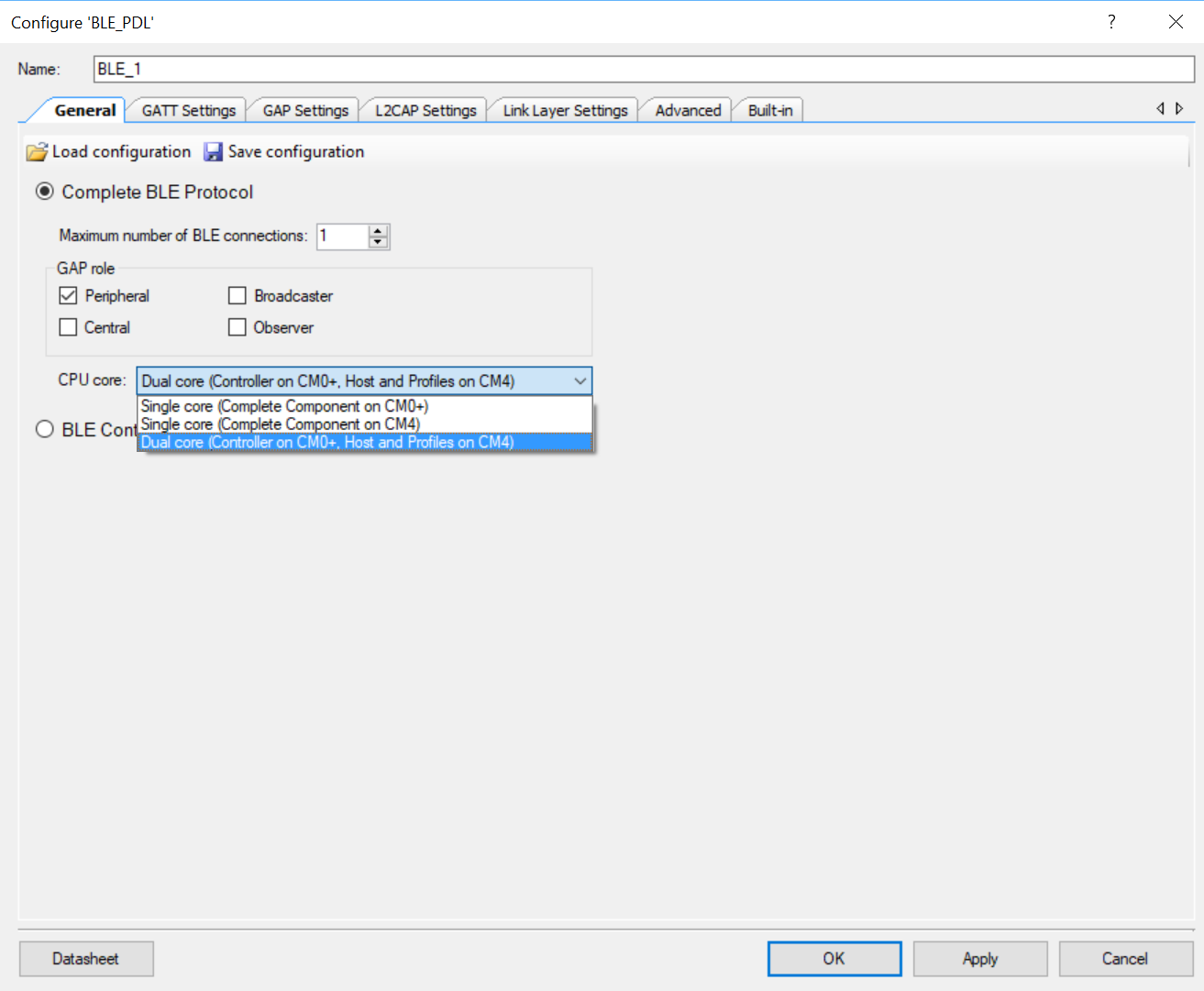
Configure the component to be a “Dual Core …” and set the number of connections to 1.
Add the Capsense service to your server by clicking “Load Service…”
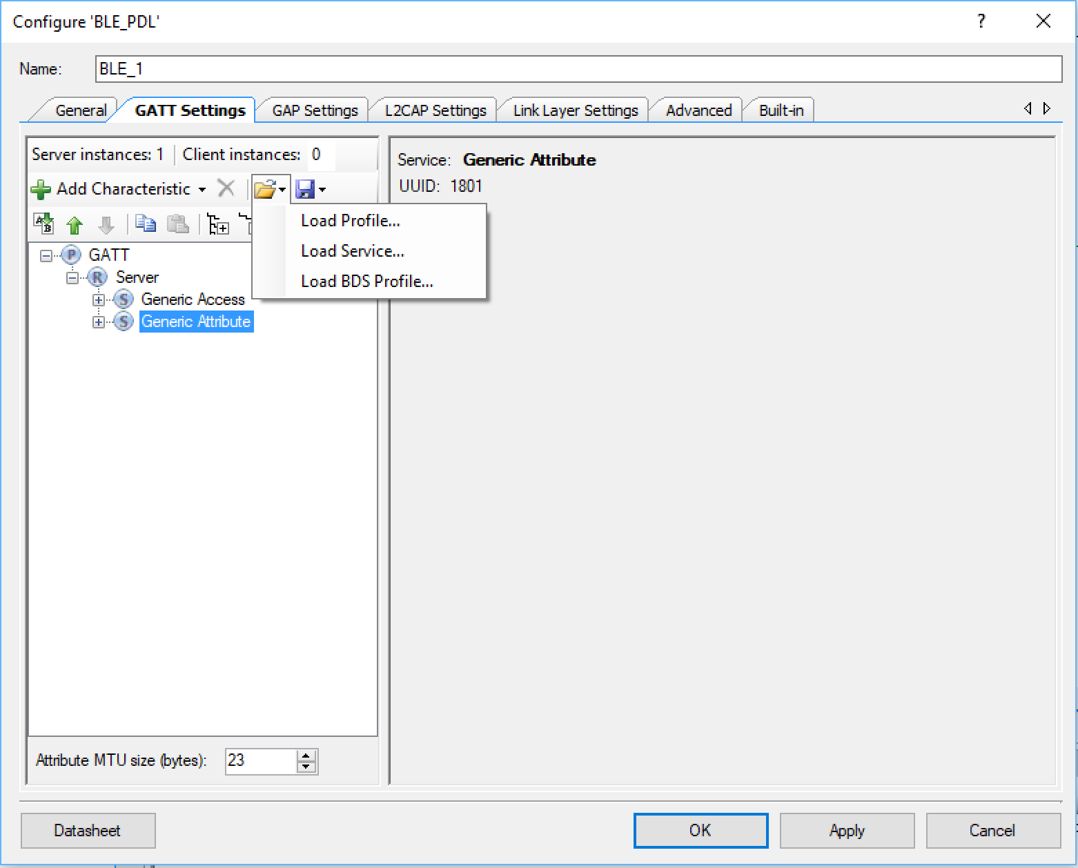
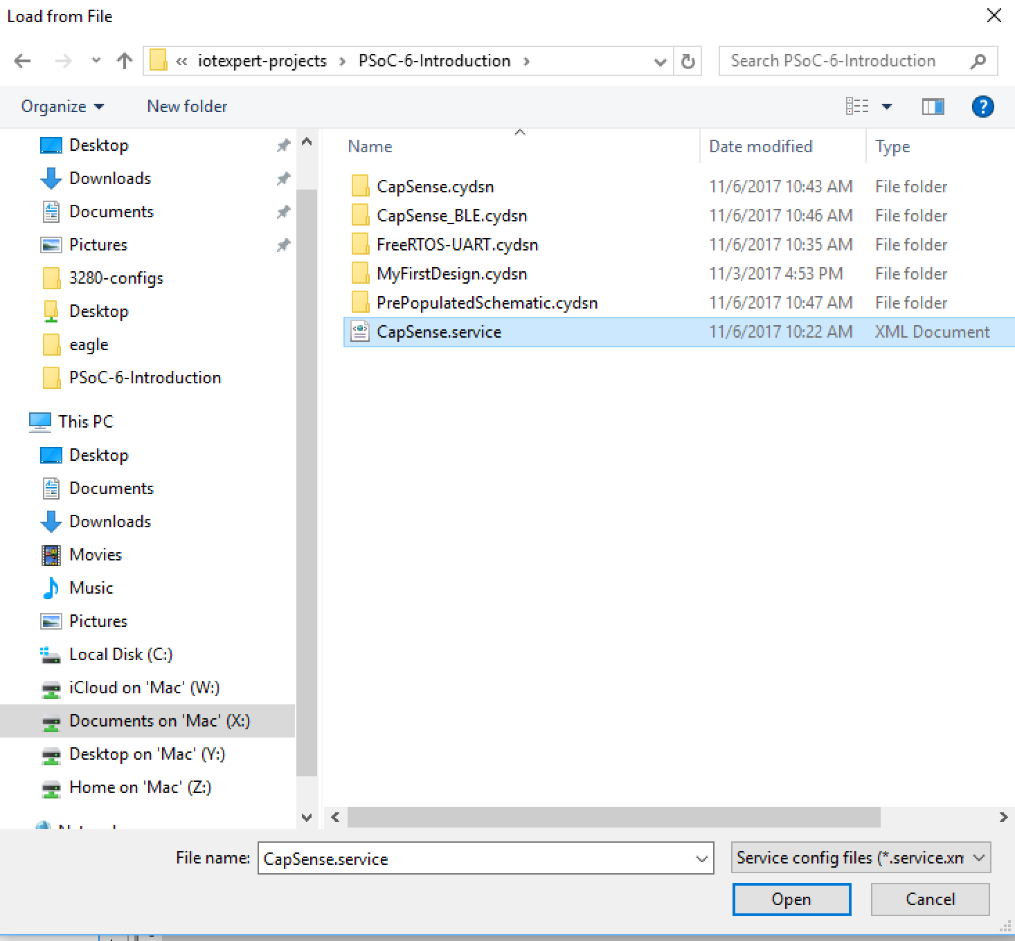
And selecting the “CapSense.service” file. I created this file to have the right UUIDs and characteristics.
You can now look at the CapSense Slider service and the CapSlider characteristic

Set the name of our peripheral in the “GAP Settings”. In this case I will call it P6INTRO.
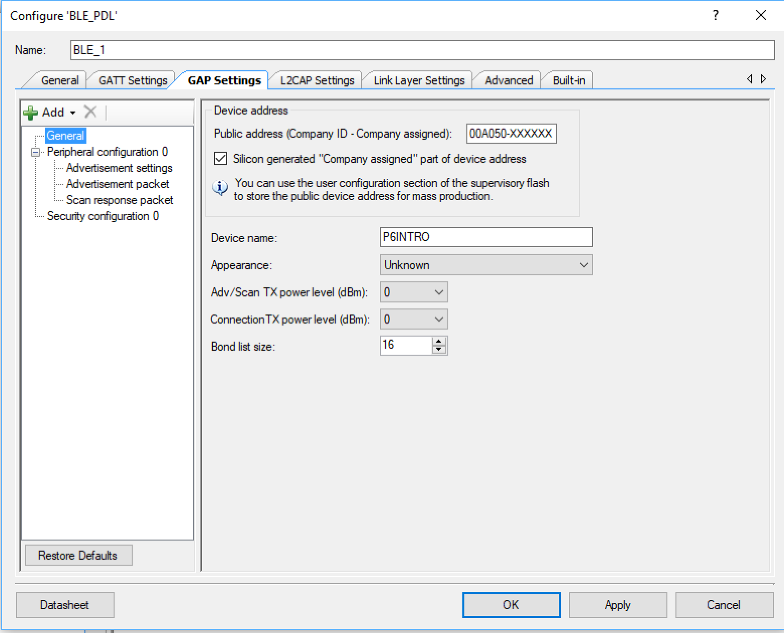
Configure the advertising settings to advertise the name of the device and the CapSense Service.

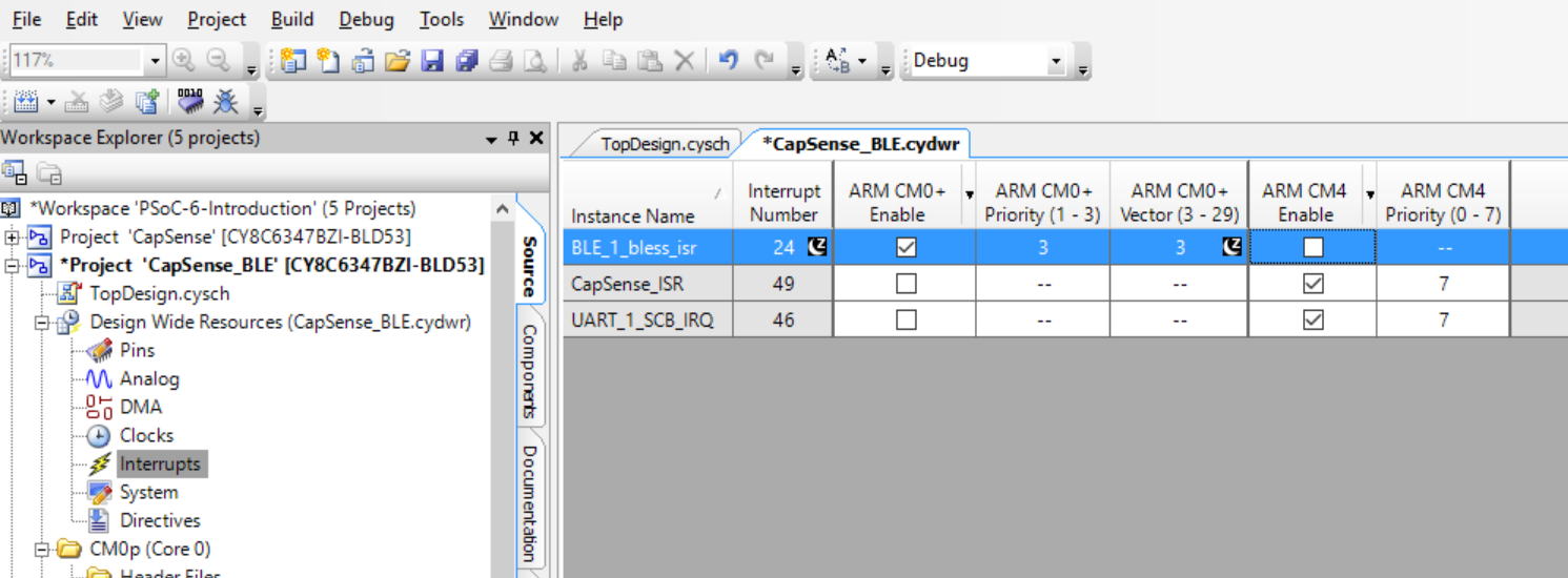
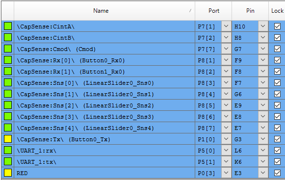
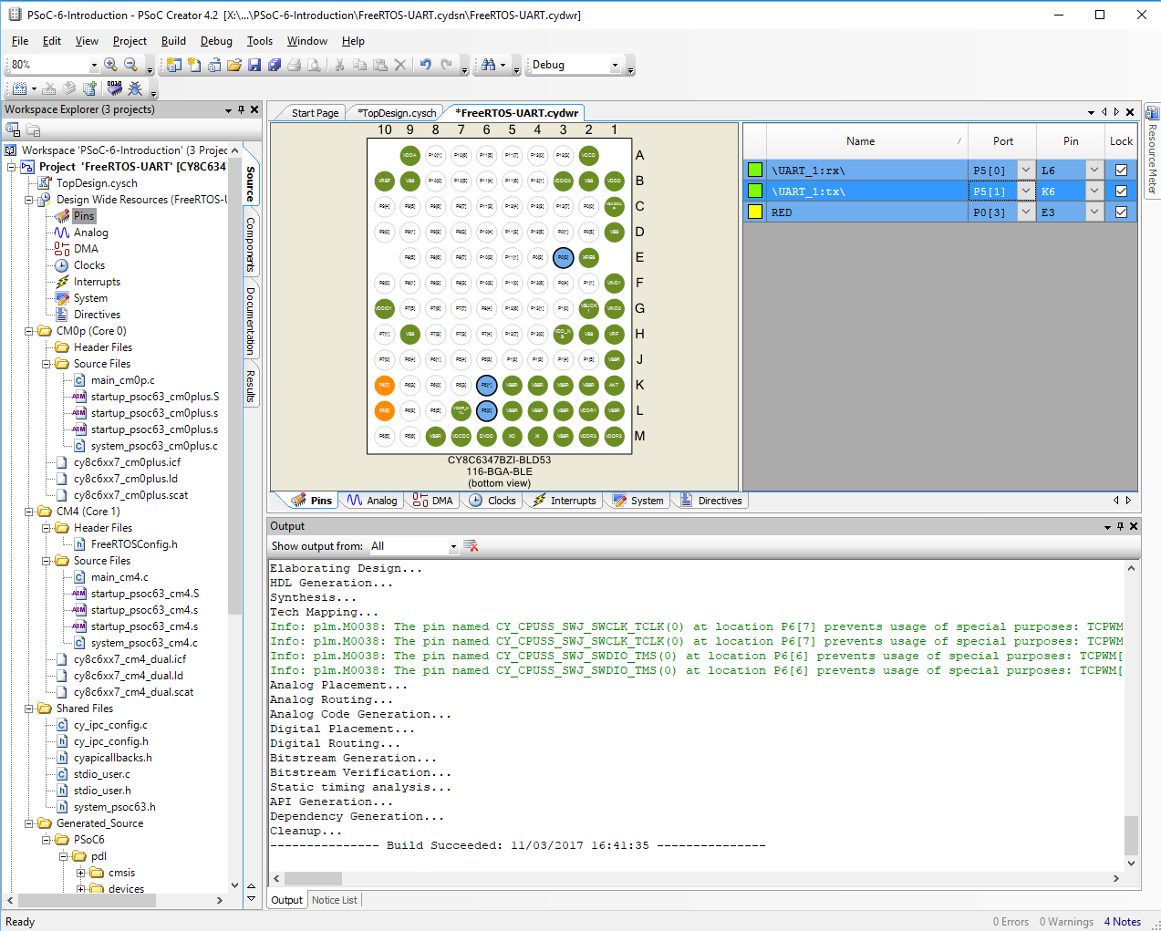
Fix the Interrupts
Almost all of the interrupt sources in the PSoC 6 can be connected to one or both of the Cortex cores. I think that you are probably crazy to attach it to both. In this case the BLE interrupt needs to be connected to the “ARM CM0+”
Update main_cm0p. c to Run the BLE Radio Controller
#include <project.h>
int main(void)
{
    __enable_irq(); /* Enable global interrupts. */


    Cy_BLE_Start(0);

    /* Enable CM4.  CY_CORTEX_M4_APPL_ADDR must be updated if CM4 memory layout is changed. */
    Cy_SysEnableCM4(CY_CORTEX_M4_APPL_ADDR);


    for(;;)
    {
        Cy_BLE_ProcessEvents();
    }
}
Add three global variables to main_cm4.c
The BLE Task will have a queue that the CapSense will use to send out changes in the CapSense Slider.
QueueHandle_t bleQueueHandle;
int connected=0;
int notify=0;
Create a new task to process the BLE
The. task will just start up the BLE processing on the CM4. Then it will cause the BLE event manager to run. If a new value of the CapSense slider is set, it will send out a notification using the “notifyCapSense” function
// bleTask handles the BLE connection (or not).. if the user connects and turns on
// notifications then it sends out new values of the CapSense slider
void bleTask(void *arg)
{
    (void)arg;
    uint32_t msg;

    printf("Starting BLE Task\r\n");
    bleQueueHandle = xQueueCreate(1,sizeof(uint32_t));
    Cy_BLE_Start(customEventHandler);

    for(;;)
    {
        Cy_BLE_ProcessEvents();

        // CapSense task will put CapSense slider values in the bleQueueHandle
        if(xQueueReceive(bleQueueHandle,&msg,0) == pdTRUE)
            notifyCapSense((uint8_t)msg);

        taskYIELD();
    }
}
Create an Event Handler
You will need a task to handle the BLE processing on the CM4. Each time a Bluetooth event occurs you will need to do “something”
// This event handler is called by BLE
void customEventHandler(uint32_t event, void *eventParameter)
{
     cy_stc_ble_gatts_write_cmd_req_param_t   *writeReqParameter;

    switch (event)
    {
        case CY_BLE_EVT_STACK_ON:
        case CY_BLE_EVT_GAP_DEVICE_DISCONNECTED: // Central disconnects
            Cy_BLE_GAPP_StartAdvertisement(CY_BLE_ADVERTISING_FAST,CY_BLE_PERIPHERAL_CONFIGURATION_0_INDEX);
            connected = 0;
            notify=0;
        break;

        case CY_BLE_EVT_GATT_CONNECT_IND: // A Central connection is made
            connected = 1;
        break;

        case CY_BLE_EVT_GATTS_WRITE_REQ:
            writeReqParameter = (cy_stc_ble_gatts_write_cmd_req_param_t *)eventParameter;

            if(CY_BLE_CAPSENSE_CAPSLIDER_CLIENT_CHARACTERISTIC_CONFIGURATION_DESC_HANDLE ==  writeReqParameter->handleValPair.attrHandle)
                notify = writeReqParameter->handleValPair.value.val[0];

            Cy_BLE_GATTS_WriteRsp(writeReqParameter->connHandle);
        break;

        default: // Ignore all other events
        break;
    }
}
Make a Function to Send Notifications
// This function is run inside BLE Task and sends notification if you are connected and notifications are on
void notifyCapSense(uint8_t capValue)
{
    if(!(connected && notify))
        return;

    cy_stc_ble_gatts_handle_value_ntf_t v1;
    v1.connHandle = cy_ble_connHandle[0];
    v1.handleValPair.attrHandle = CY_BLE_CAPSENSE_CAPSLIDER_CHAR_HANDLE;
    v1.handleValPair.value.len = 1;
    v1.handleValPair.value.val = &capValue;

    Cy_BLE_GATTS_Notification(&v1);

}
EDIT!!!!
If you look at the source code at GitHub you will find that I removed the variables “connected” and “notify” and I changed the notifyCapSense function. This was done because the BLE PDL implementation was greatly improved and simplified. The new function iterates through the connections and sends the notification to all of them. This was done to handle multiple connections.
// This function is run inside BLE Task and sends notification if you are connected and notifications are on
void notifyCapSense(uint8_t capValue)
{

    unsigned int index;

    printf("Sending CapSense %d\r\n",capValue);

    cy_stc_ble_gatt_handle_value_pair_t handleValuePair;
    handleValuePair.attrHandle = CY_BLE_CAPSENSE_CAPSLIDER_CHAR_HANDLE;
    handleValuePair.value.val = &capValue;
    handleValuePair.value.len = 1;

    Cy_BLE_GATTS_WriteAttributeValueLocal(&handleValuePair);

    /* Iterate and send notiication to all the connected devices that are ready to receive notification */
    for(index = 0; index <CY_BLE_CONN_COUNT; index++)
    {
        Cy_BLE_GATTS_SendNotification(&cy_ble_connHandle[index], &handleValuePair);
    }

}
Update the capSenseTask to Send Values
Inside of the capsenseTask you need to send new values of the slider to the BLE task via the Queue. Meaning the BLE task needs to send out notifications, but it can only do that if the capsenseTask notifies it of changes.
sliderPos=CapSense_GetCentroidPos(CapSense_LINEARSLIDER0_WDGT_ID);
            if(sliderPos<0xFFFF) // If they are touching the slider then send the %
            {
                msg = sliderPos;
                xQueueSend(pwmQueueHandle,&msg,0); // Send message to PWM - change brightness
                xQueueSend(bleQueueHandle,&msg,0); // Send message to BLE
            }
Add the bleTask to main function in main_cm4.c
In the main function you need to start the BLE Task.
xTaskCreate( bleTask, "BLE Task",4096,0,3,0);
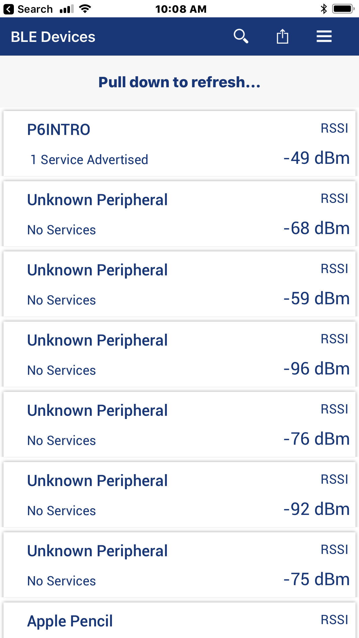
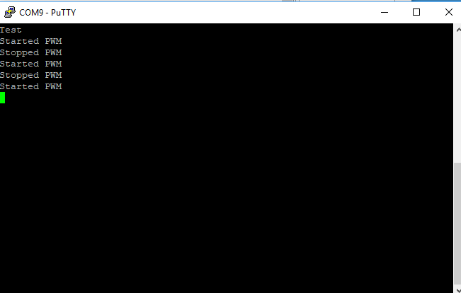
Program and Test
To test this project I will run the CySmart iOS App. First, you can see all of the devices that are advertising
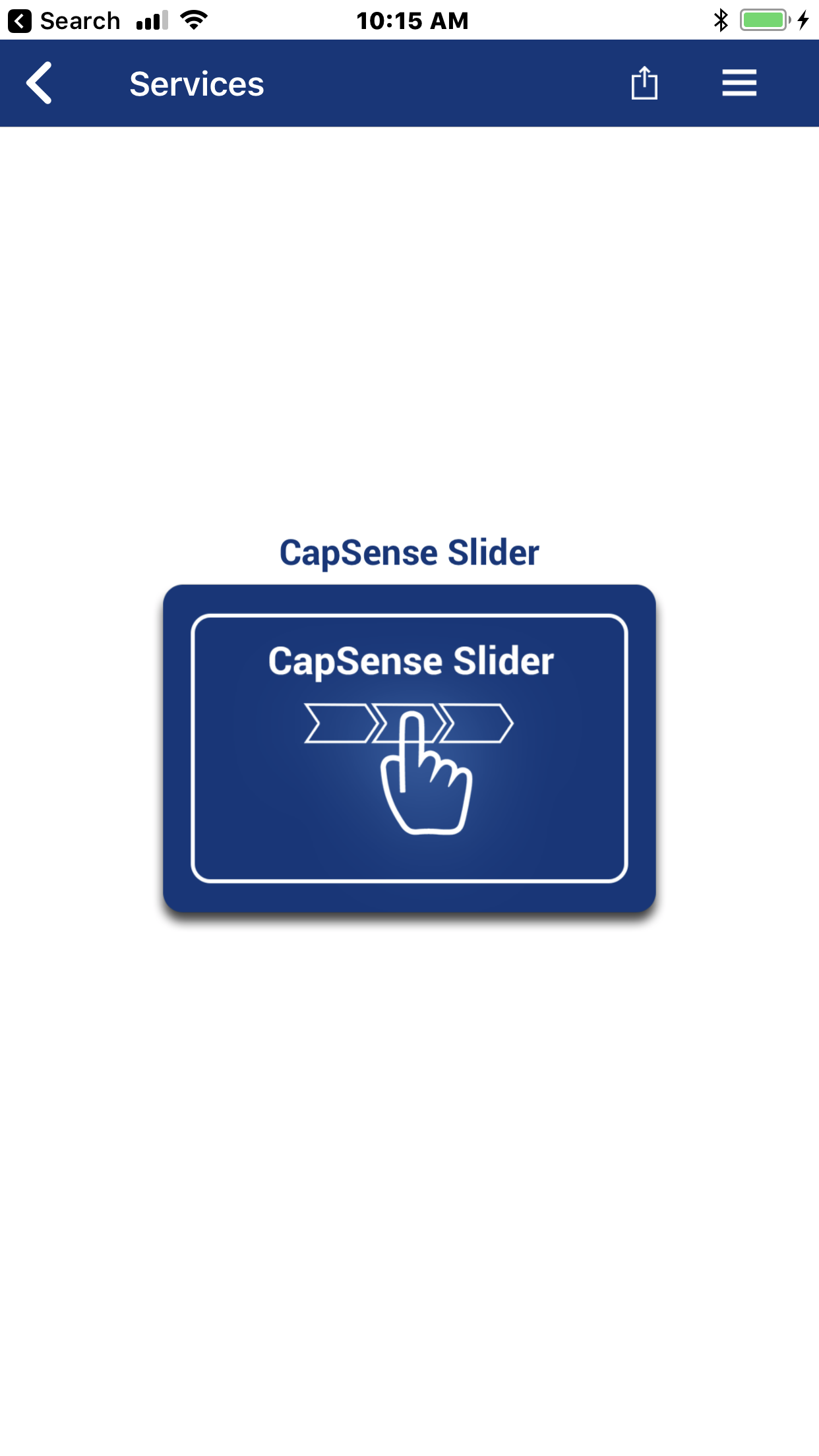
Scroll left (or right) to find the “CapSense Slider”
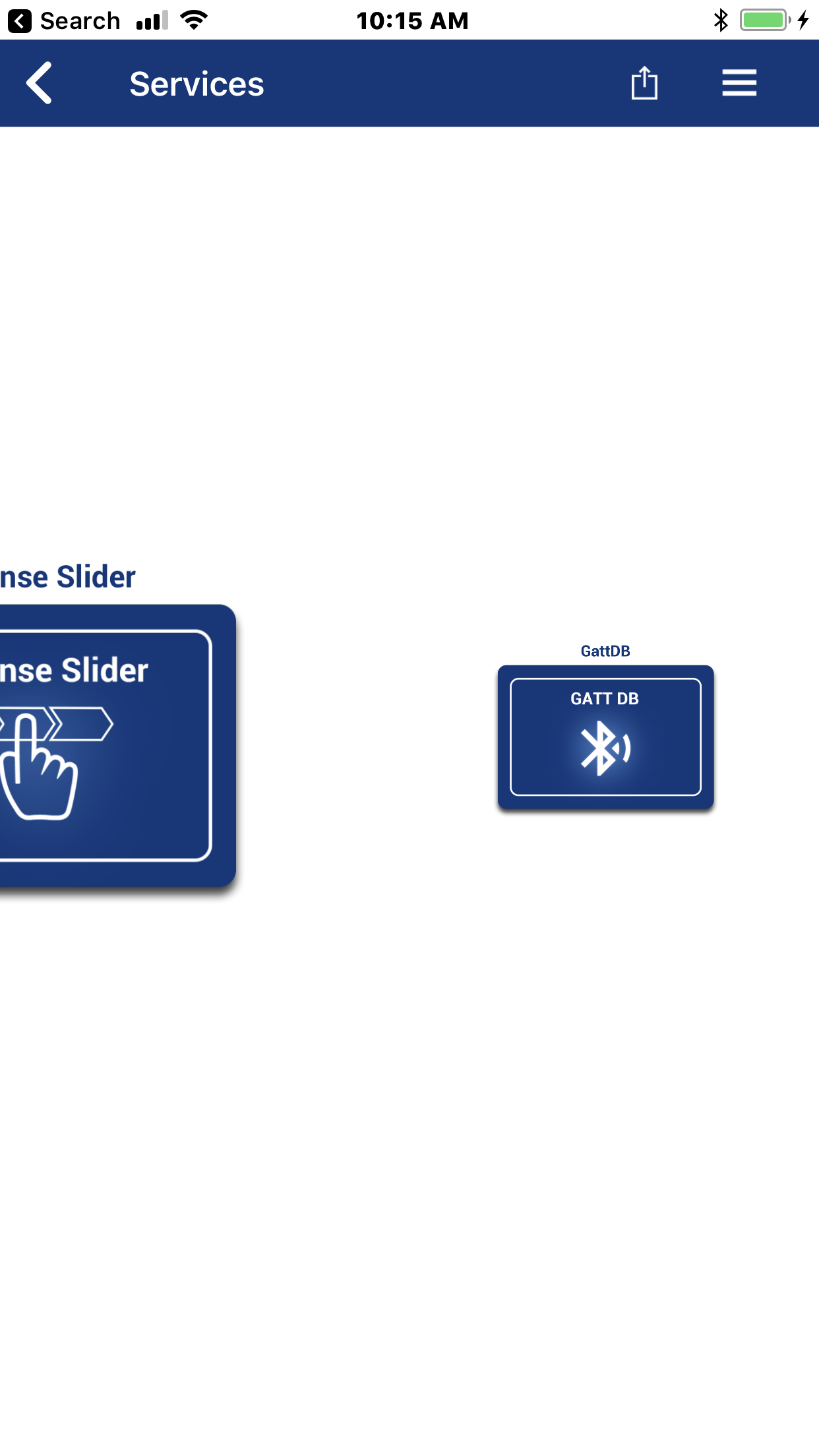
When you see it, Press on the CapSense Slider Icon
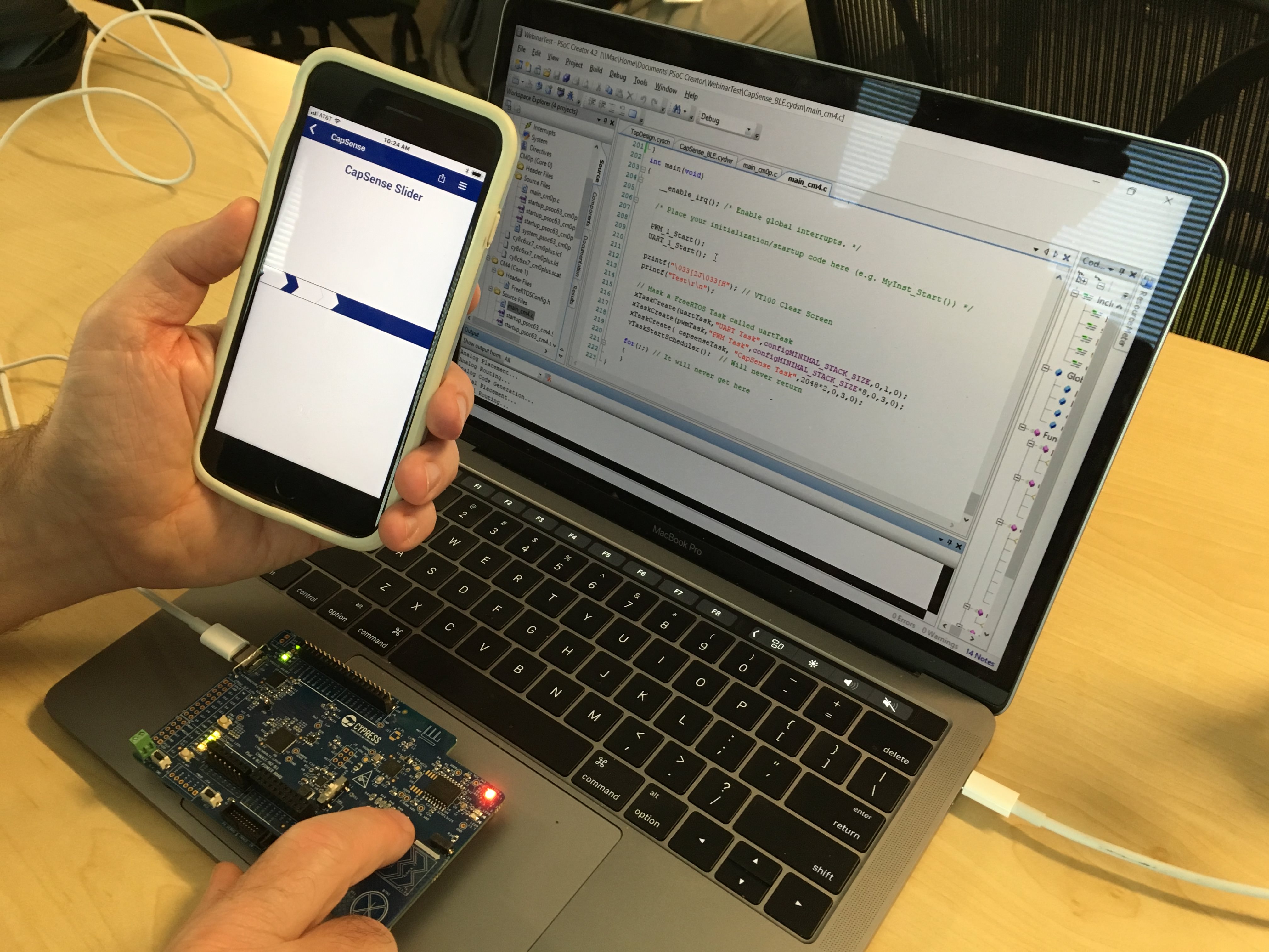
Then put your finger on the slider and you should see it change

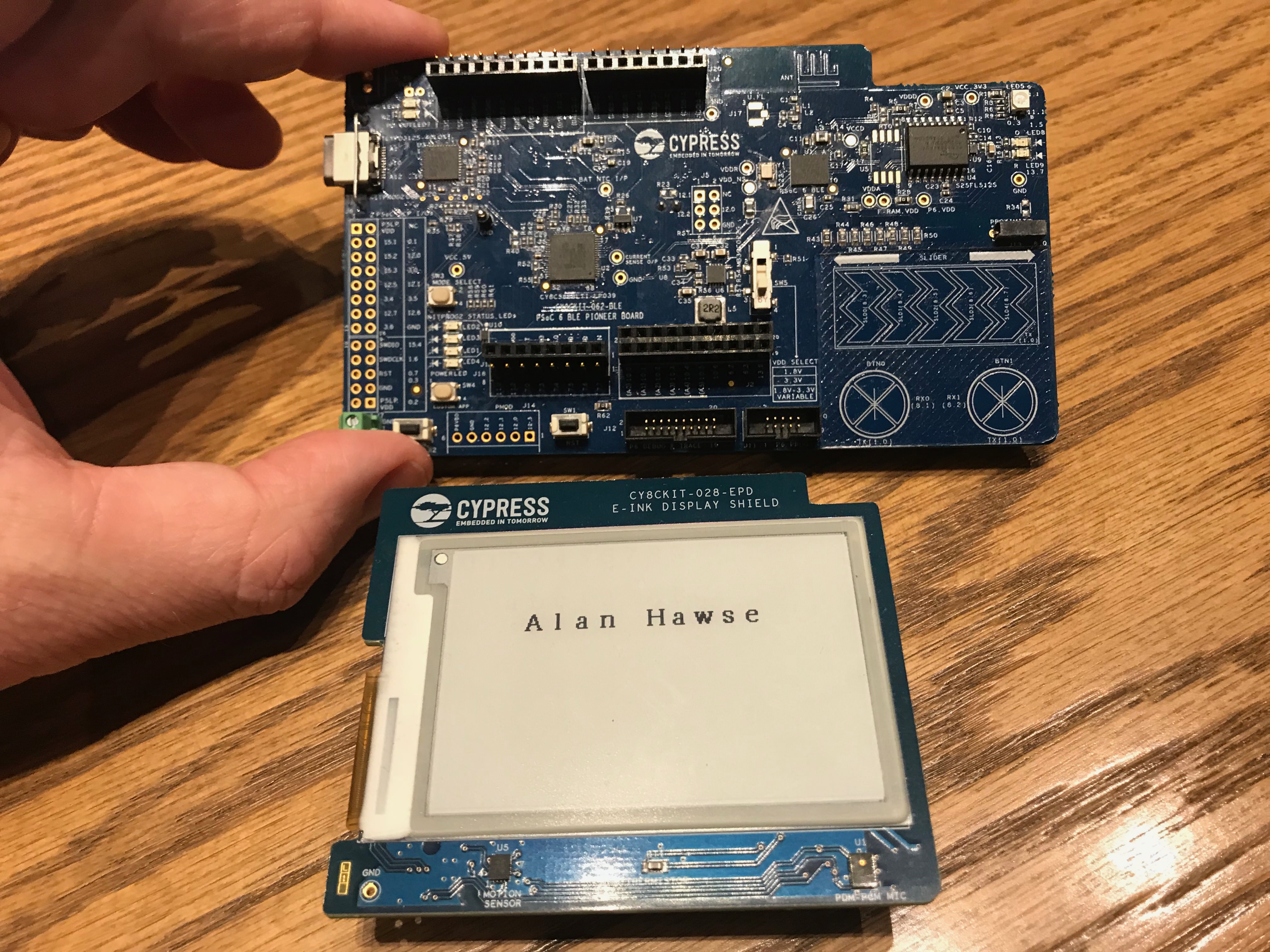
Here is a picture of the whole system.


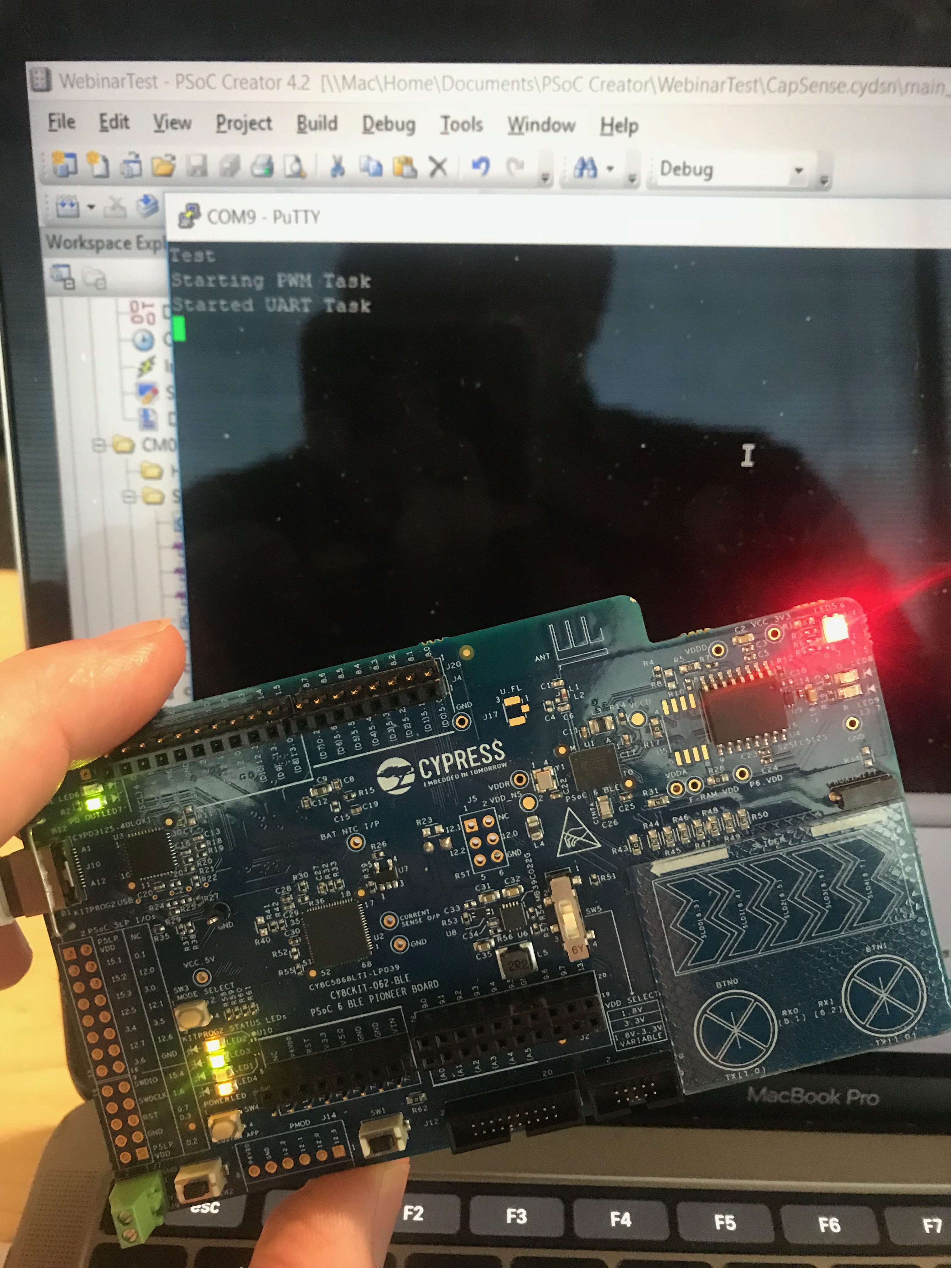
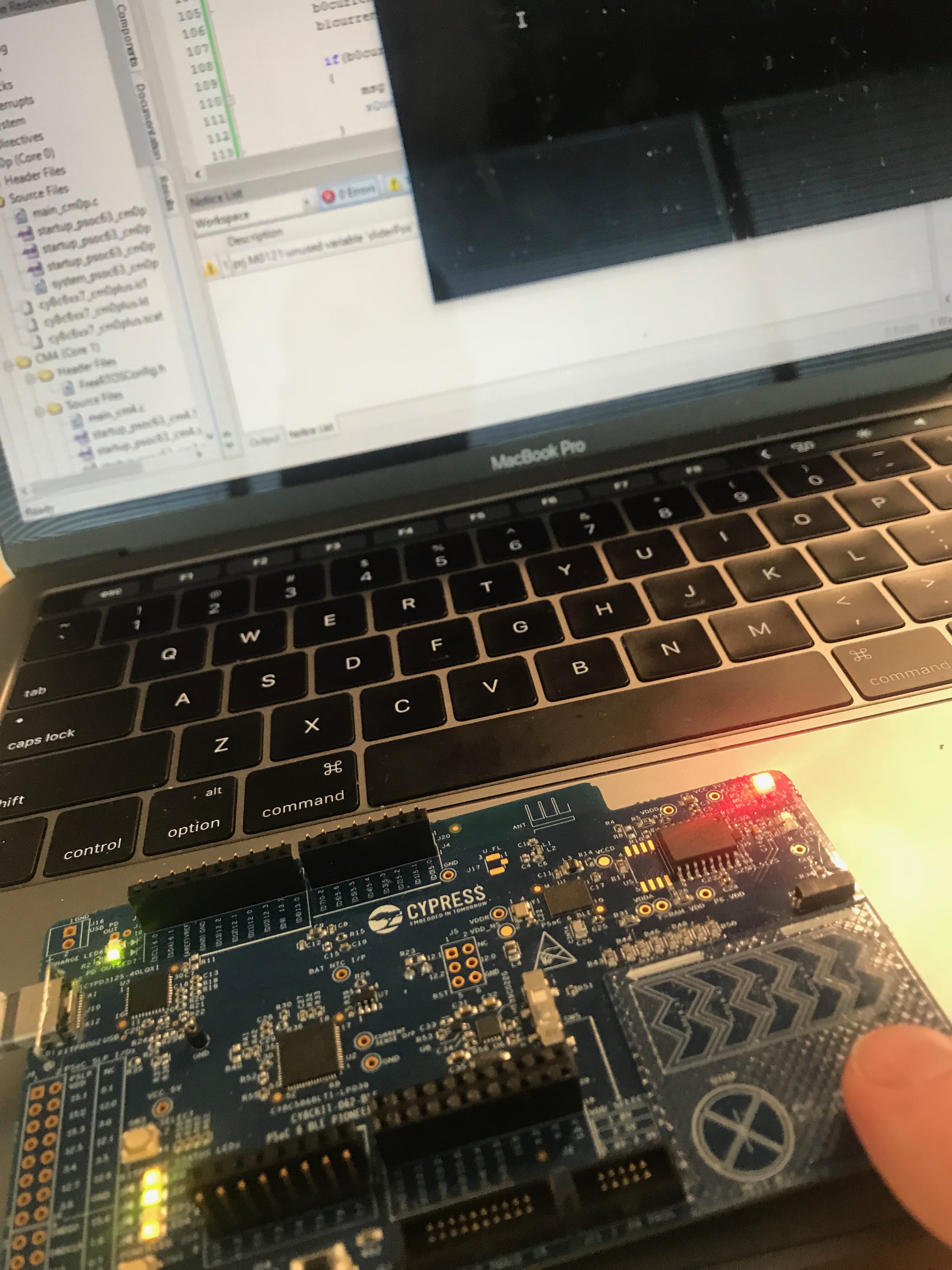

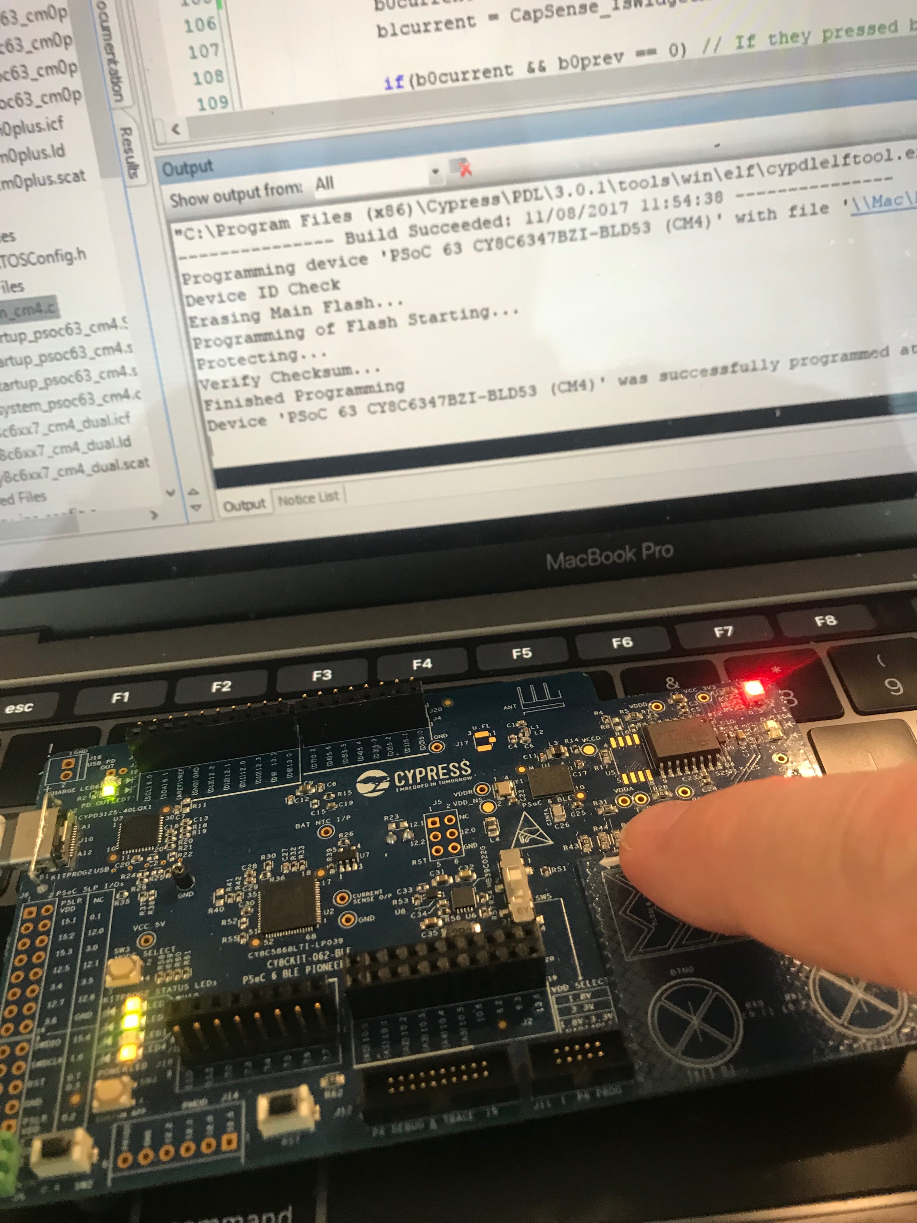


