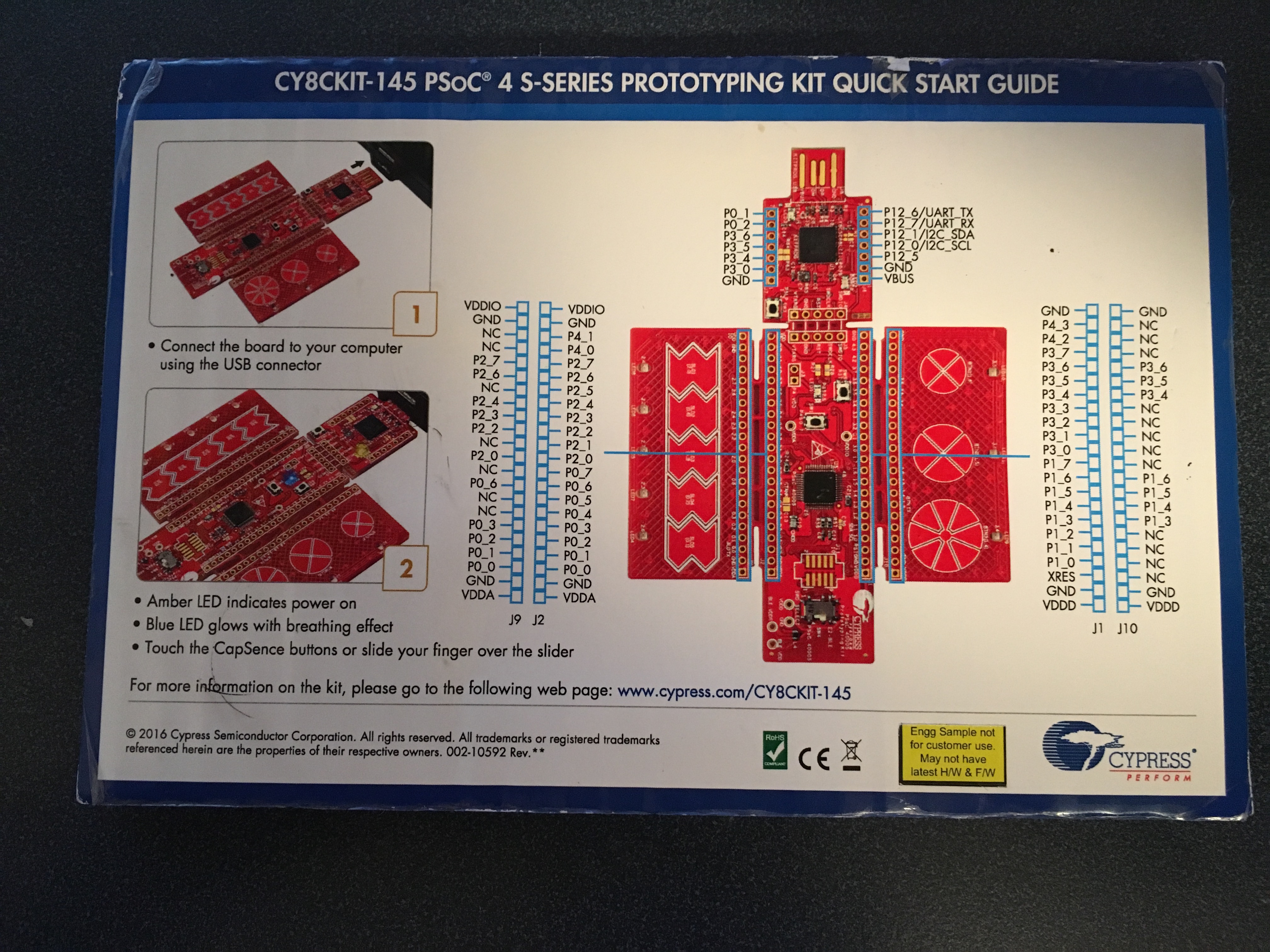
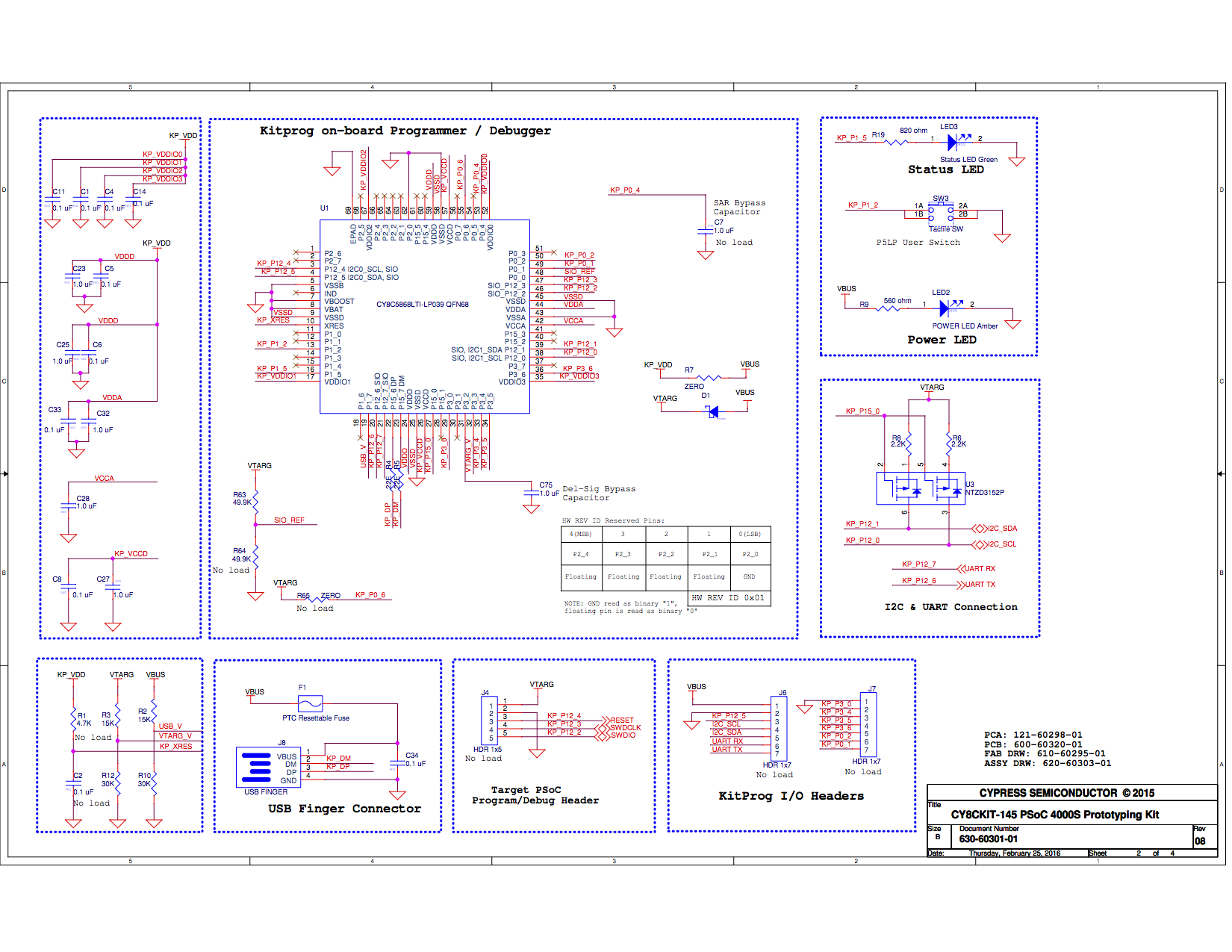
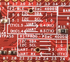
In the previous post, I unboxed the CY8CKIT145 and showed you the schematics. In this post, I will show you how to build the CapSense firmware that runs on the PSoC4000S. The first decision I needed to make was how to connect the PSoC and the PRoC chips. So I looked at the back of the kit and there was a handy-dandy picture of the schematic in the silkscreen. Here is a zoomed in view:
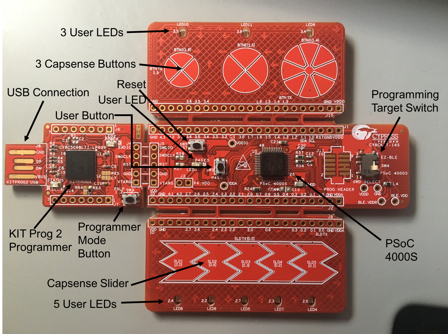
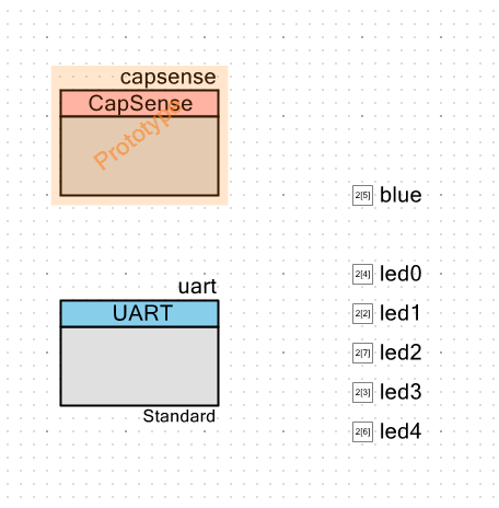
I didn’t have the schematic on the airplane, but here is a more “schematic” view of the chips on the board.

I knew that the UART source code would be slightly easier, so I picked that as the mechanism to connect the chips. On my computer I had the “capsenseled” workspace from the videos. So, I created a new PSoC4000S project in that workspace called “145capsenseled.” I started with the schematic:
- Add the new CapSense component. I am currently running a “nightly build” of PSoC Creator 3.3 that supports the new chip. You can see in the PSoC Creator release I’m using there is a prototype version of the CapSense component.
- Add 5 Digital Output Pins under software control to drive the LEDs that are next to the slider
- Add 1 Digital Output pin to drive the blue LED
- Add a Serial Communication Block (SCB) configured as a UART
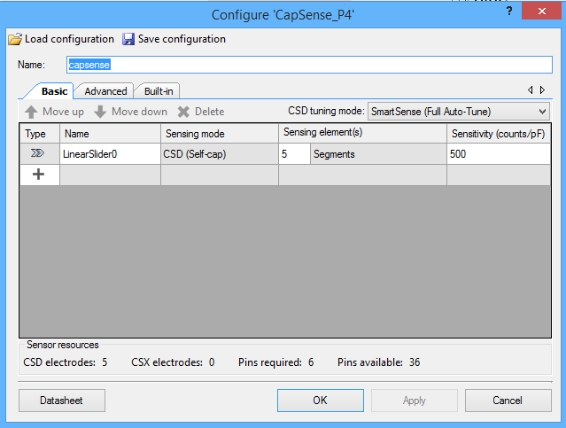
Here is a screenshot of the new CapSense component configuration wizard. You can see I added a linear slider and set up the component to use SmartSense full-auto tuning.
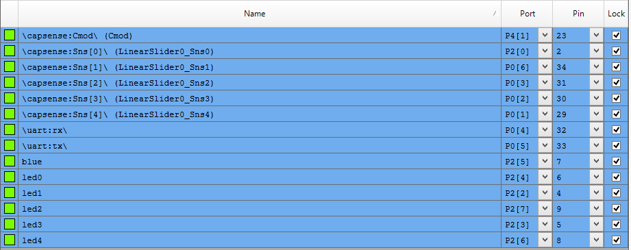
After configuring the CapSense, I set up the pin assignments using the DWR:
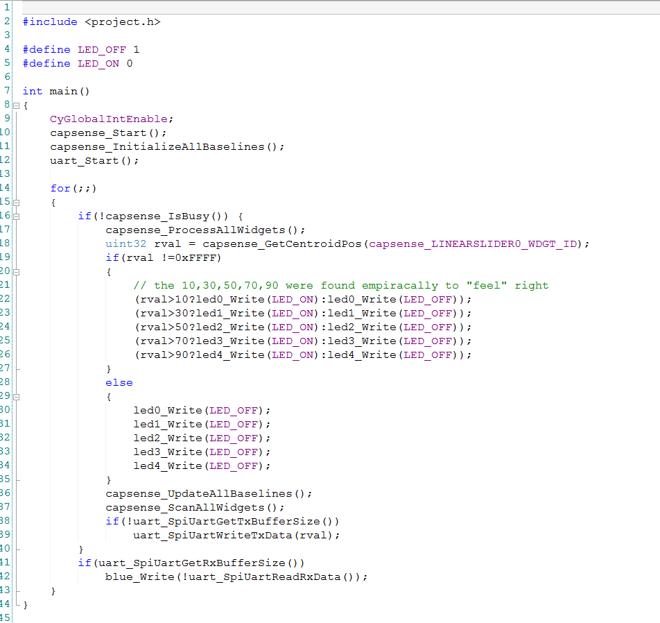
Then I wrote the firmware, which was pretty straight forward.
- 10-11 start the CapSense
- 12 start the UART
- 16: If the CapSense block is done scanning and is idle, then read the CapSense and do something with it (lines 17 -> 41).
- 18: figure out where the person is touching
- 19: if they have actually touched the block
- 22-26 light up the LEDs
- 30-35 If there is no touch, then turn off the LEDs.
- 36-37 start the next scan
- 38-39: If the UART is not busy… then send the position (0-100) or (0xFF if there is no touch).
- 41-42: If there is a byte in the UART receive buffer, then light up or turn off the Blue LED. (Notice that the LED is active low so I use the “!” operation to flip the state of the signal.
After that, I programmed the kit and tested it. It seemed like everything was good. In the next post, I’ll show you the schematic and firmware that runs on the PRoC BLE.
You can find the PSoC Creator workspace on github in the directory called “capsenseble-145.”
Index
Description
PSoC4000s and the CY8CKIT145 Stamp Board - Part 1
The board and schematics
PSoC4000s and the CY8CKIT145 Stamp Board - Part 2
PSoC4000S Firmware
PSoC4000s and the CY8CKIT145 Stamp Board - Part 3
PRoC BLE Firmware
PSoC4000s and the CY8CKIT145 Stamp Board - Part 4
Debugging the problem