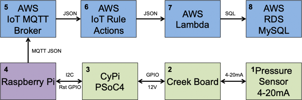
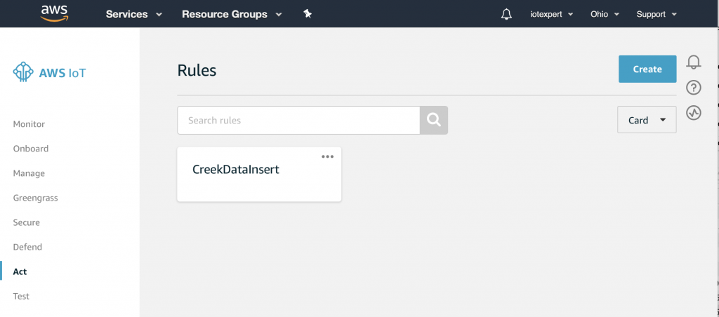
Summary
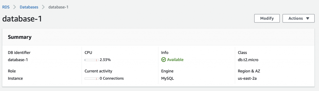
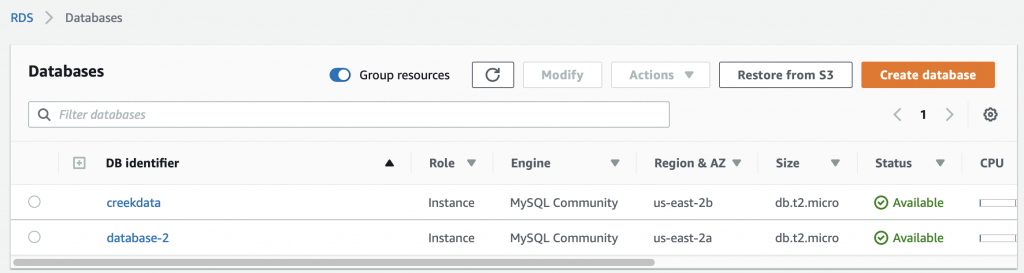
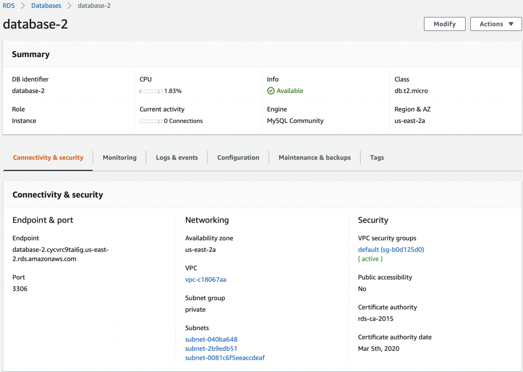
At this point in the Creek 2.0 series I have data that is moving from my sensor into the AWS IoT core via MQTT. I also have a VPC with an AWS RDS MySQL database running. In order to get the data from the AWS IoT Device Shadow into the database, I am left with a two remaining steps:
- Create a Lambda Function which can run when asked and store data into the Database (this article)
- Connect the IoT MQTT Message Broker to the Lambda Function (the next article)
This article addresses the Lambda Function, which unfortunately is best written in Python. I say ‘unfortunately’ because I’ve always had enough self-respect to avoid programing in Python – that evil witch’s brew of a hacker language. 🙂 But more seriously, I have never written a line of code in Python so it has been a bit of a journey. As a side note, I am also interested in Machine Learning and the Google TensorFlow is Python driven, so all is not lost.
For this article, I will address:
- What is an AWS Lambda Function?
- Create a Lambda Function
- Run a Simple Test
- Install the Python Libraries (Deployment Package)
- Create a MySQL Connection and Test
- Configure the Lambda Function to Run in your VPC
- Create an IAM Role and Assign to the Lambda Function
- Update the Lambda Function to Insert Data
- The Whole Program
What is an AWS Lambda Function?
AWS Lambda is a place in the AWS Cloud where you can store a program, called a Lambda Function. The name came from the “anonymous” function paradigm which is also called a lambda function in some languages (lisp was the first place I used it). The program can then be triggered to run by a bunch of different things including the AWS IoT MQTT Broker. The cool part is that you don’t have to manage a server because it is magically created for you on demand. You tell AWS what kind of environment you want (Python, Go, Javascript etc), then AWS automatically creates that environment and runs your Lambda function on demand.
In this case, we will trigger the lambda function when the AWS IoT Message Broker accepts a change to the Device Shadow. I suppose that the easiest way to understand is to actually build a Lambda Function.
Create a Lambda Function
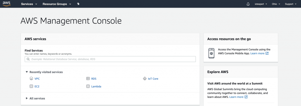
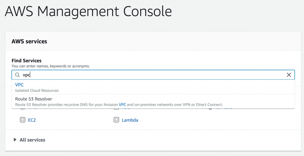
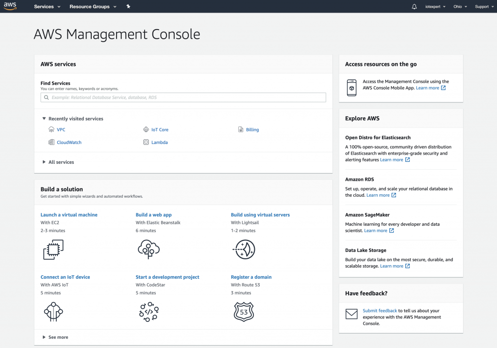
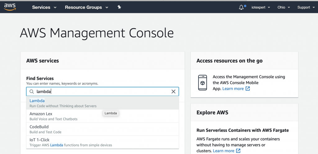
To create a Lambda function you will need to go to the Lambda management console. To get there, start on the AWS Management console and search for “lambda”
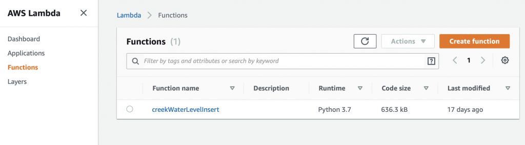
On the Lambda console, click “Functions” then “Create function”
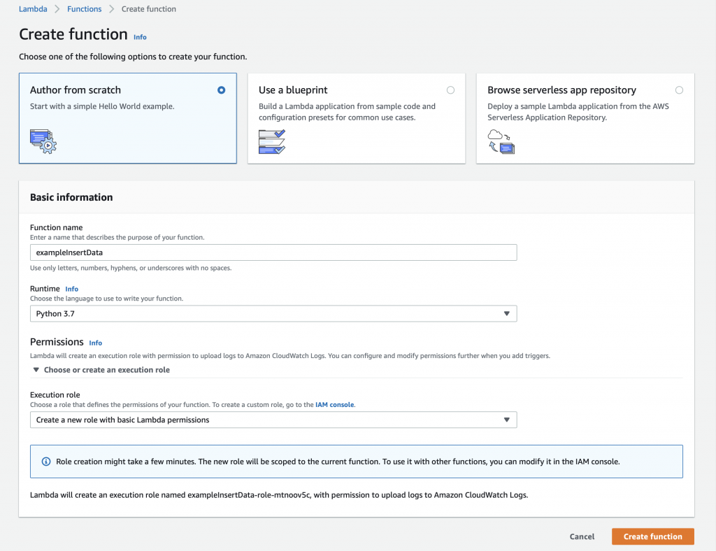
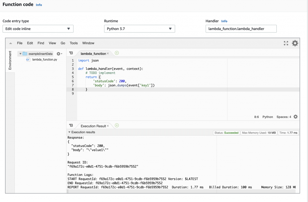
We will build this function from scratch… oh the adventure. Give the function a name, in this case “exampleInsertData”. Finally, select the Runtime. You have several choices including “Python 3.7” which I suppose was the lesser of evils.
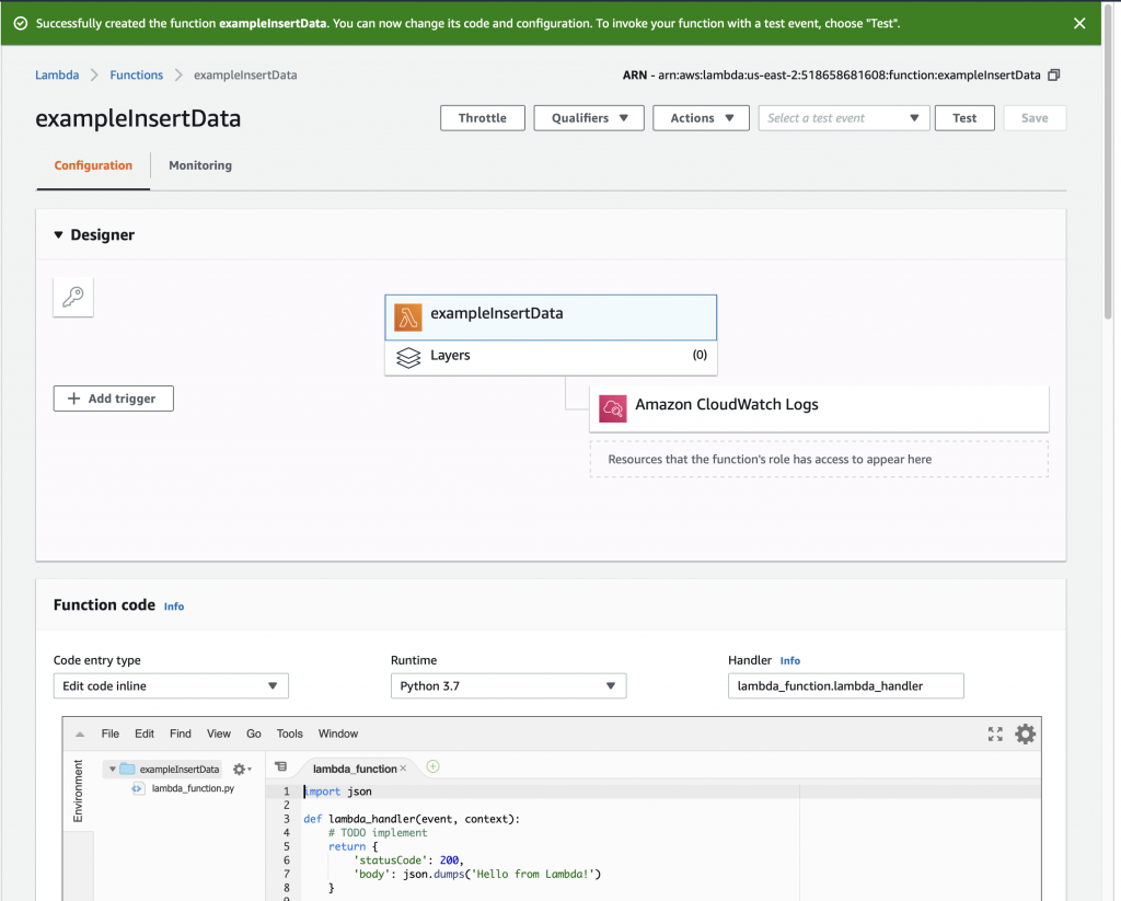
Once you click “Create function” you will magically arrive at this screen where you can get to work. Notice that the AWS folks give you a nice starter function.
Run a Simple Test
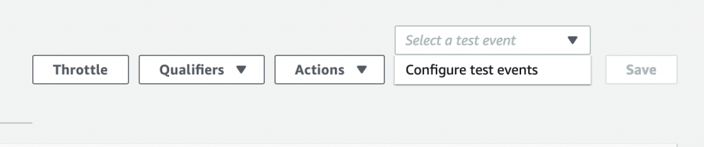
Now the we have a simple function let us run a simple test – simple, eh? To do this, click on the drop down arrow where it says “Select a test event” and then pick out “Configure test events”
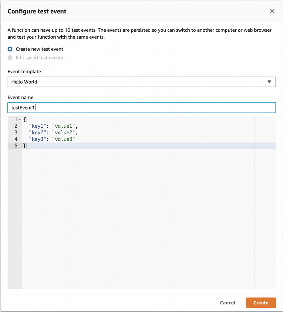
On the configure test event screen, just give your event the name “testEvent1” and click “Create”
Now you can select “testEvent1” and then click “Test”

This will take the JSON message that you defined above (actually you let it be default) and send it into the Lambda program. The console will show you the output of the whole mess in the “Execution result: …” Press the little “Details arrow” to see everything. Notice that the default function sends a JSON keymap with two keys.
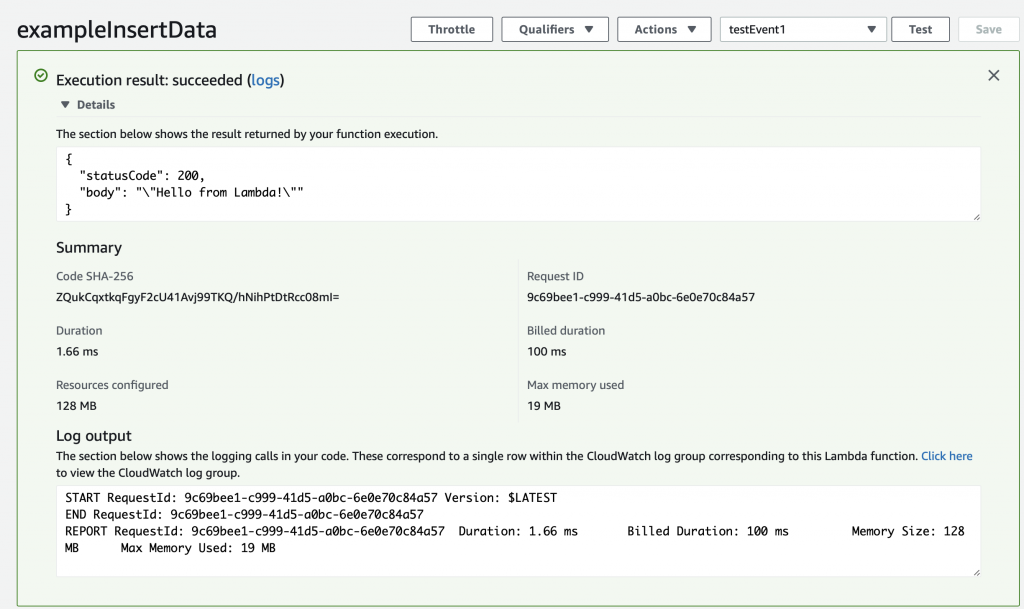
When you function runs, an object is created inside of your Python program called “event” that is the JSON object that was sent to the Lambda function. When we created the testEvent1 it gave us the option to specify the JSON object which is used as the argument to the function. The default was a keymap with three keys key1,key2 and key3.
{
  "key1": "value1",
  "key2": "value2",
  "key3": "value3"
}
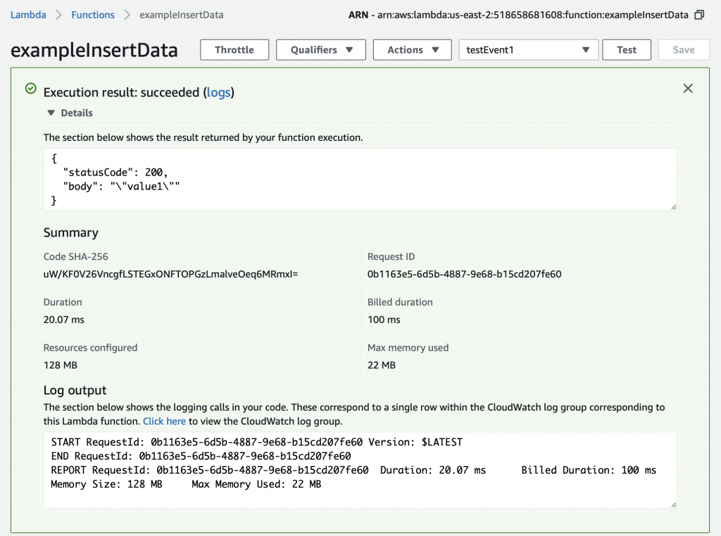
Instead of having the function return “Hello from Lambda” lets have it return the value that goes with “key1”. To do that, make a little modification to the function to “json.dumps(event[‘key1’])”. Now when you run the test you can see that it returns the “body” as “value1”.
Install Python Libraries
The default installation of Python 3.7 in Lambda does not have two libraries that I want to use. Specifically:
- pymysql – a MySQL database interface
- pytz – a library for manipulating time (unfortunately it can’t create more time)
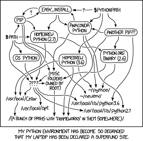
I actually don’t know what libraries are in the default Python3.7 runtime (or actually even how to figure it out?). In order to use libraries which are not part of the Python installation by default, you need to create a “Python Deployment Package“. If you google this problem, you will find an amazing amount of confusion on this topic. The humorist XKCD drew a very appropriate cartoon about this topic. (I think that I’m allowed to link it? but if not I’m sorry and I’ll remove it)
Making a deployment package is actually pretty straightforward. The steps are:
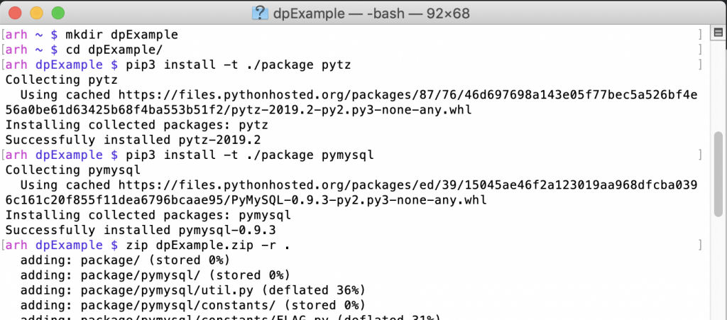
- Create a directory on your computer
- Use PIP3 to install the libraries you need in your LOCAL directory
- Zip it all up
- Upload the zip file to AWS Lambda
Here are the first three steps (notice that I use pip3)
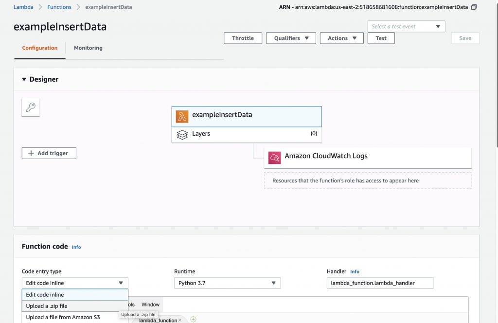
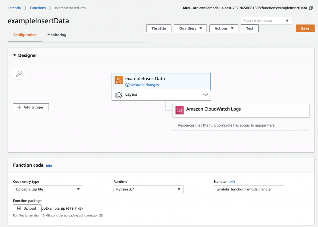
To update your AWS Lambda function, select “Upload a .zip file” on the Function code drop down.
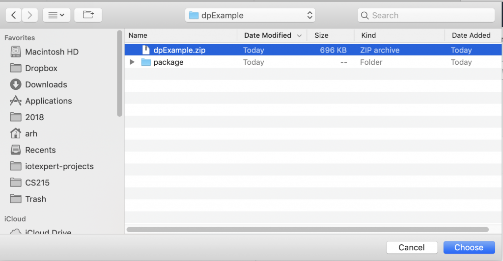
Then pick your zip file.
Now you need to press the “Save” button which will do the actual update.
After the upload happens you will get an error message like this. The problem is that you don’t have a file called “lambda_function.py” and/or that file doesn’t have a function called “lamda.handler”. AWS is right, we don’t have either of them.
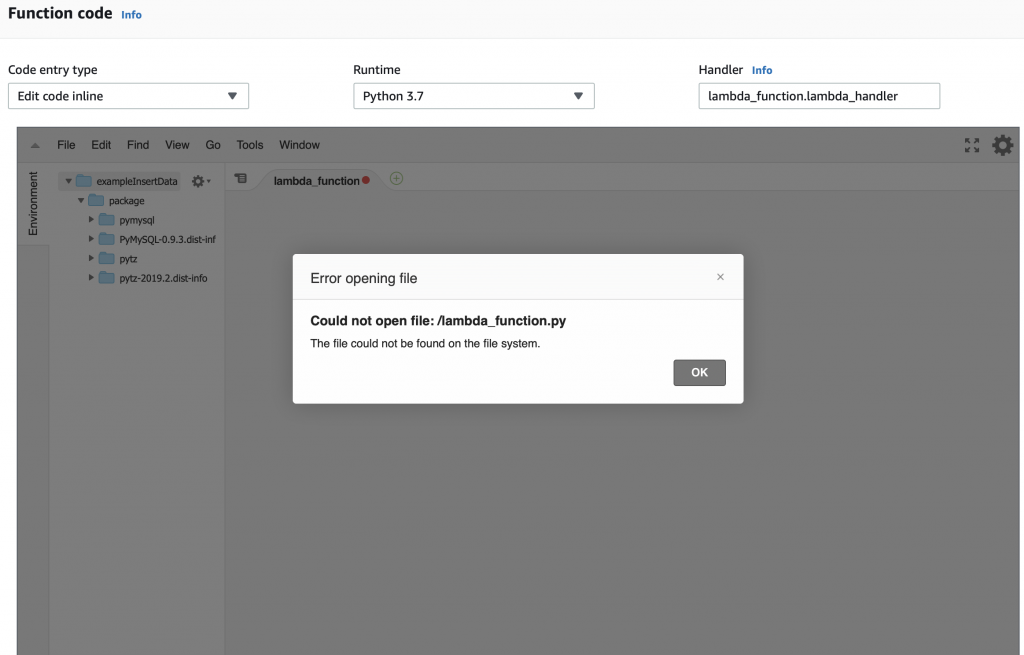
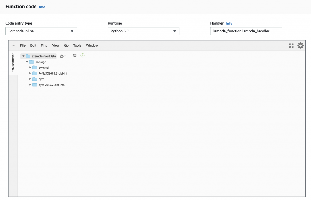
But you can see that we now have the “package” directory with the stuff we need to attach to the MySQL database and to manipulate time.
The little box that says “handler” tells you that you need to have a file called “lamda_function.py” and that Python file needs to have a function called “lambda_handler”. So let’s create that file and function. Start with “File->New File”
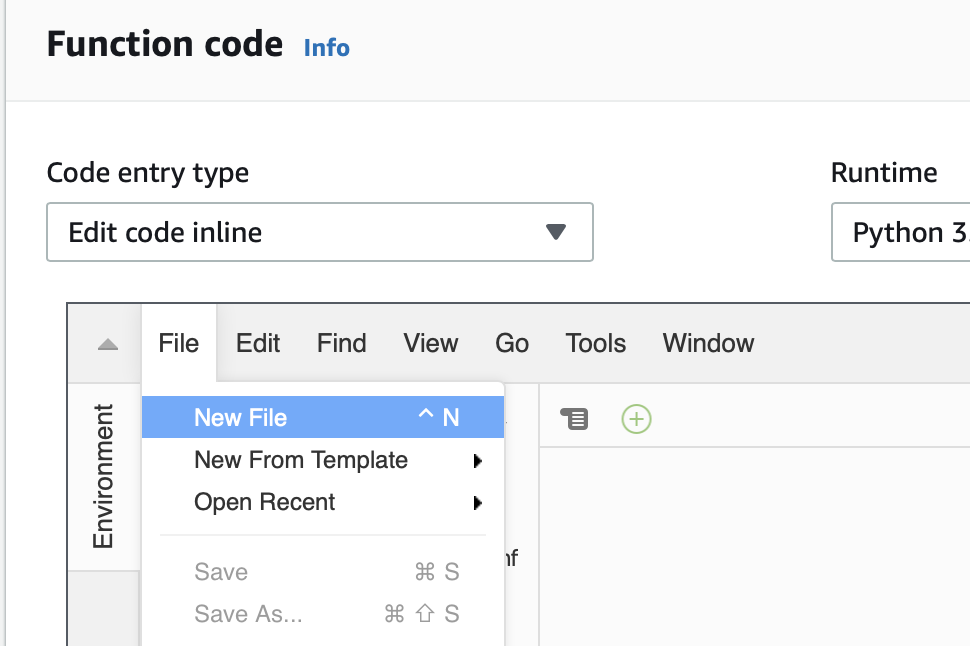
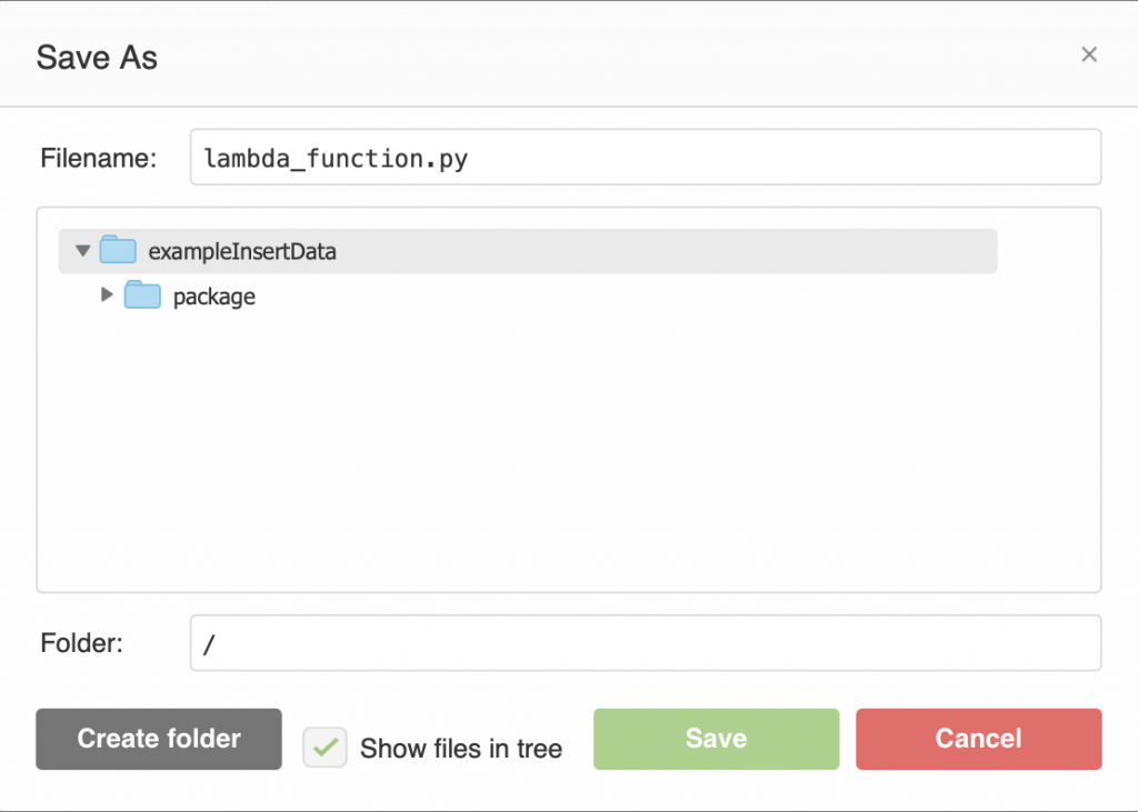
The a “File->Save As…”
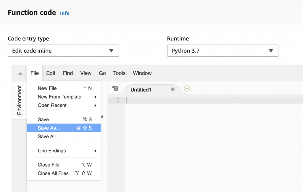
Give it the name “lambda_function.py”
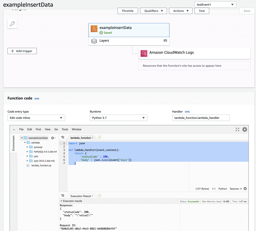
Now write the same function as before. Then press “save”. You could have created the function and file on your computer and then uploaded it as part of the zip file, but I didn’t.
import json

def lambda_handler(event,context):
    return {
        'statusCode' : 200,
        'body' : json.dumps(event['key1'])
    }
OK. Let’s test and make sure that everything is still working. So run the “testEvent1″… and you should see that it returns the same thing.
The next step is to create and test a MySQL connection.
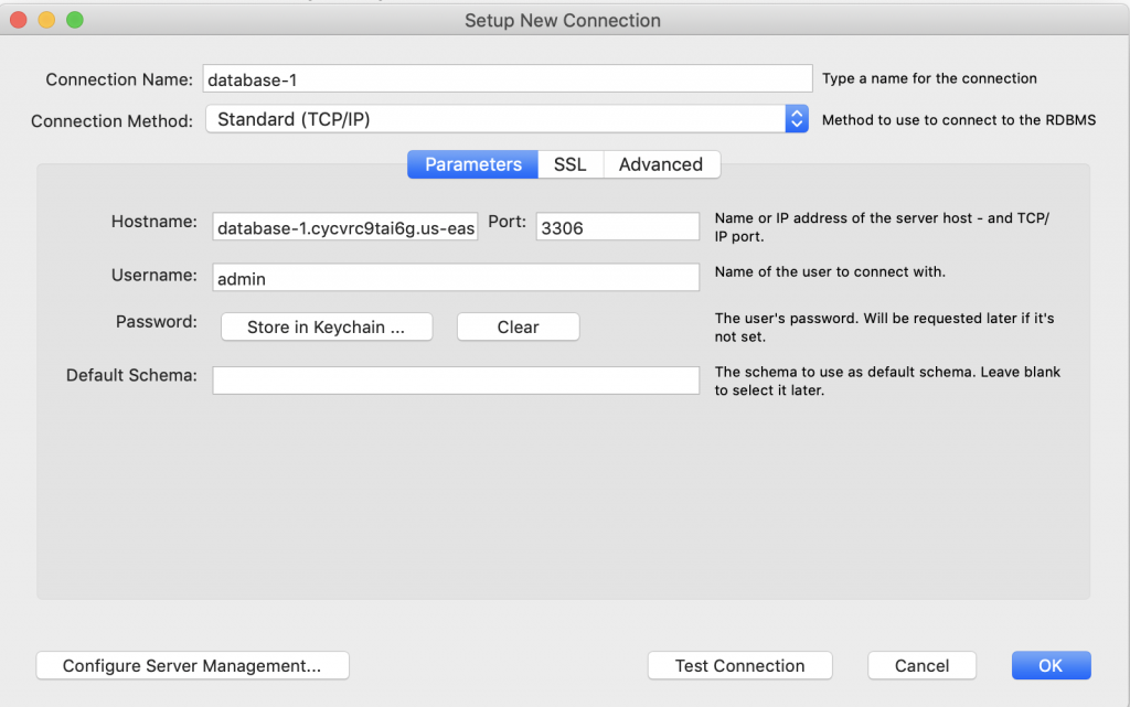
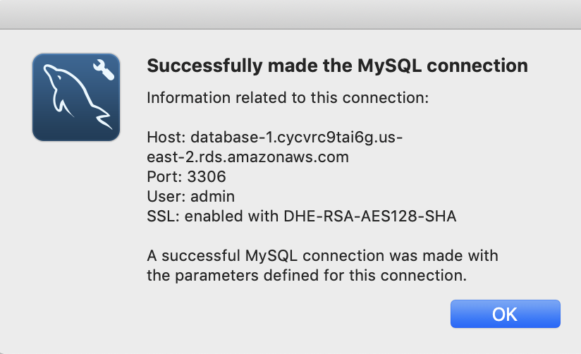
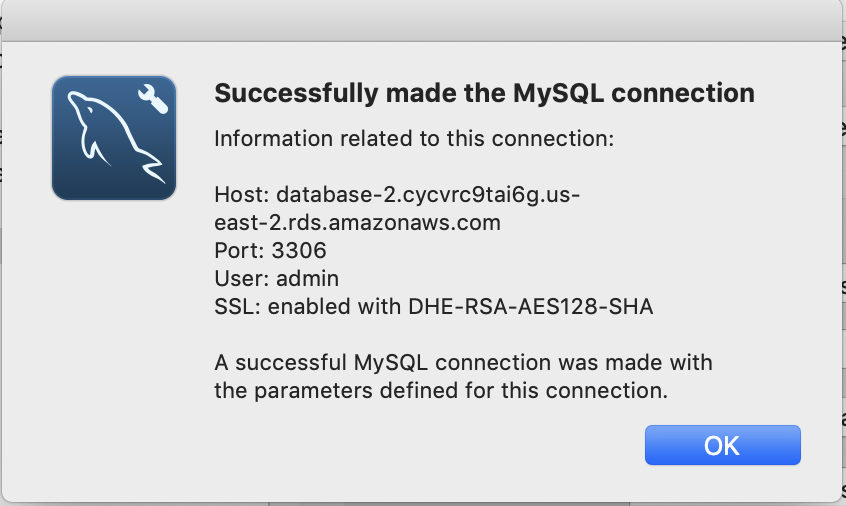
Create a MySQL Connection and Test
This simple bit of Python uses the “pymysql” library to open up a connection to the “rds_host” with the “name” and “password”. Assuming this works, the program goes on and runs the lambda_hander. Otherwise it spits out an error to the log and exits.
import json
import logging
from package import pymysql


#rds settings
rds_host  = "your database endpoint goes here.us-east-2.rds.amazonaws.com"
name = "your mysql user name"
password = "your mysql password "
db_name = "your database name"

logger = logging.getLogger()
logger.setLevel(logging.INFO)

try:
    conn = pymysql.connect(rds_host, user=name, passwd=password, db=db_name, connect_timeout=5)
except:
    logger.error("ERROR: Unexpected error: Could not connect to MySQL instance.")
    sys.exit()


def lambda_handler(event,context):
    return {
        'statusCode' : 200,
        'body' : json.dumps(event['key1'])
    }
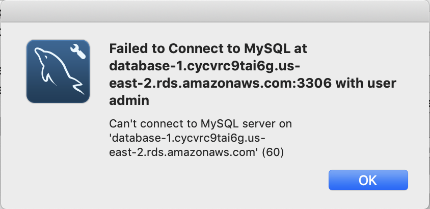
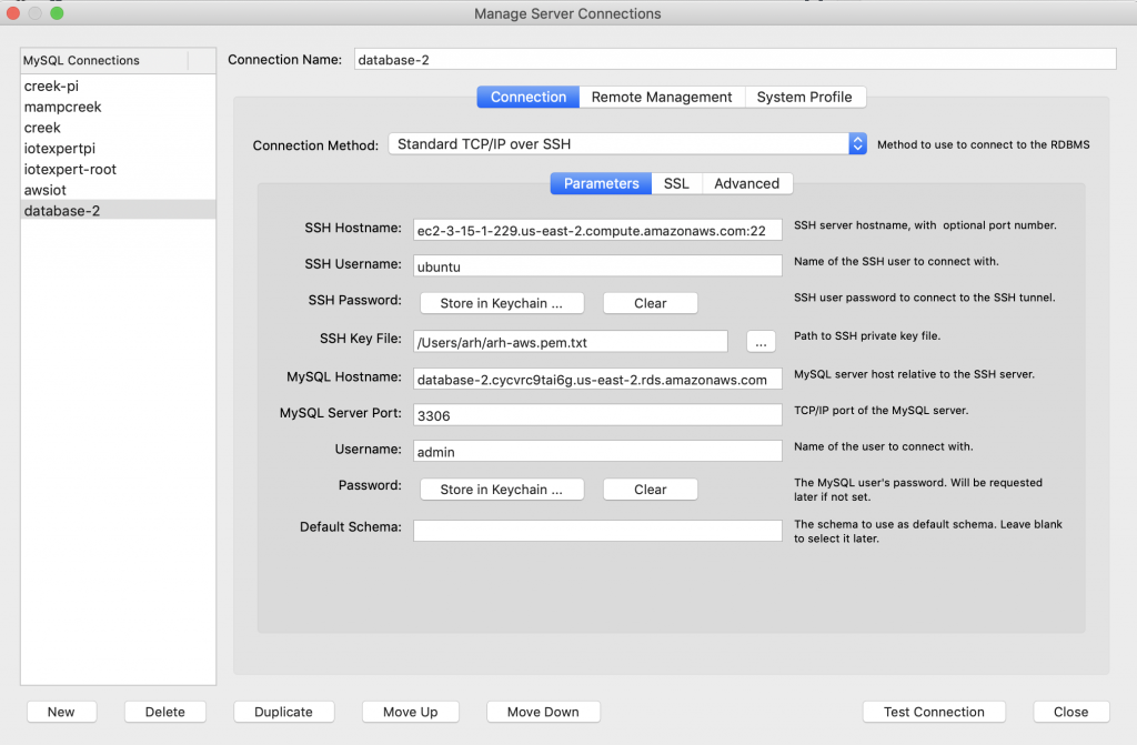
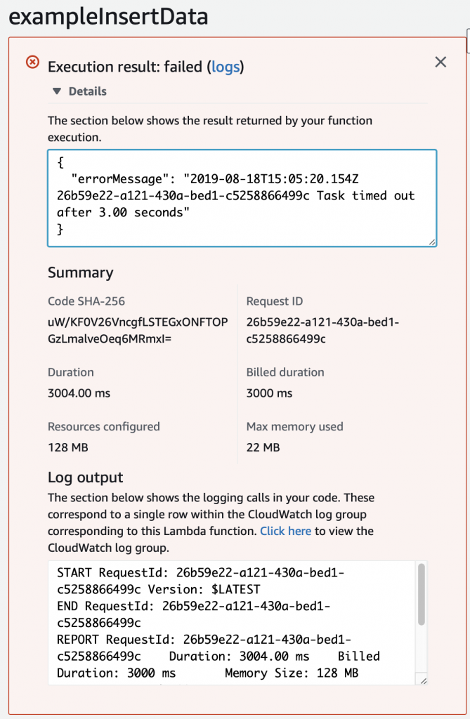
When I run the test, I get this message which took me a long time to figure out. Like a stupidly long time. In order to fix it, you need to configure the Lambda function to run in your VPC.
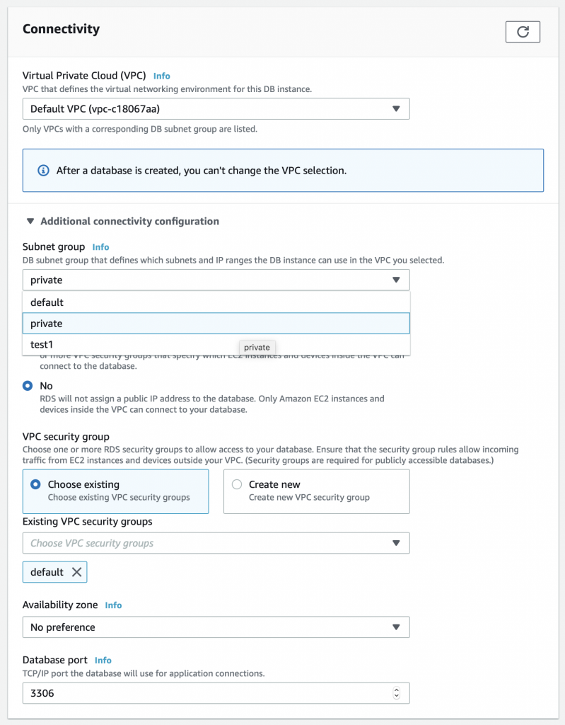
Configure the Lambda Function to Run in your VPC
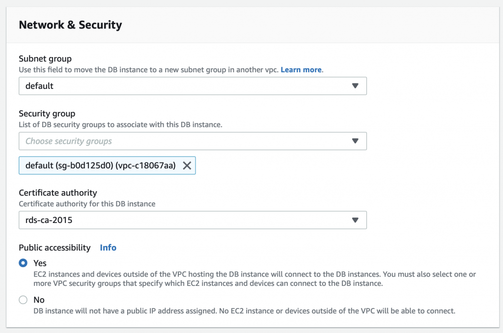
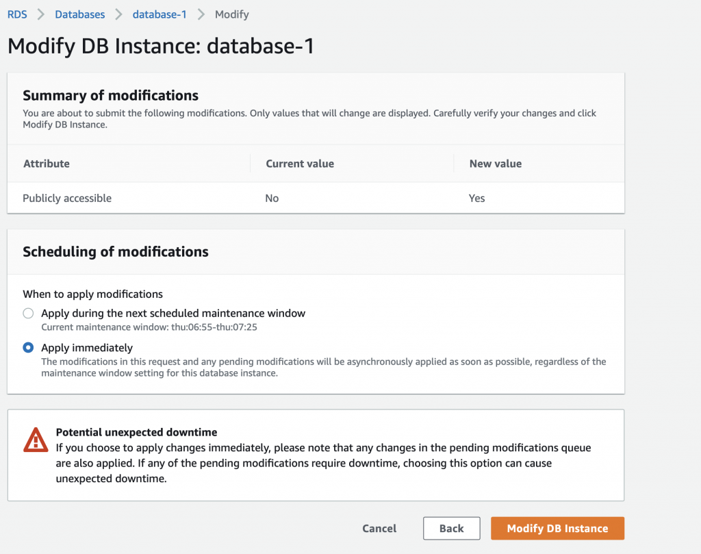
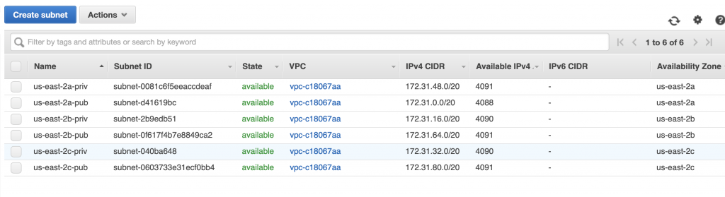
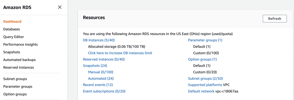
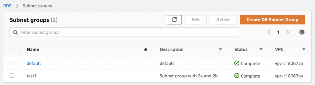
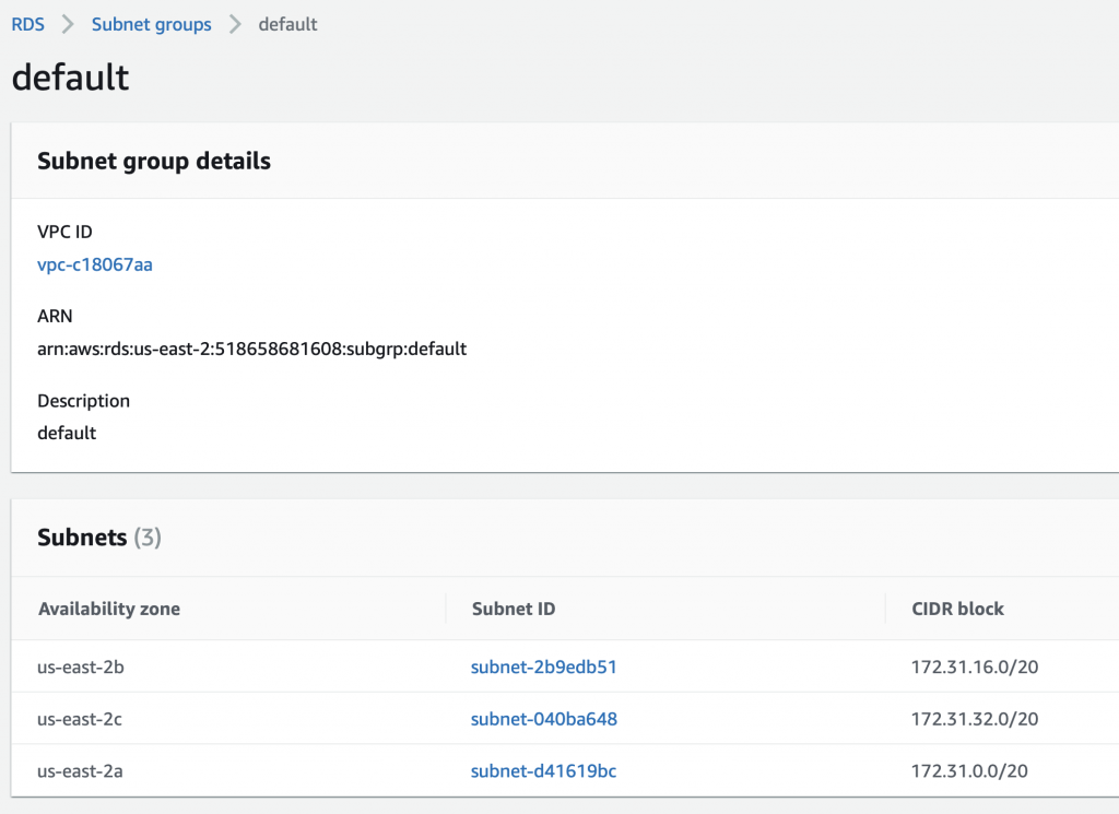
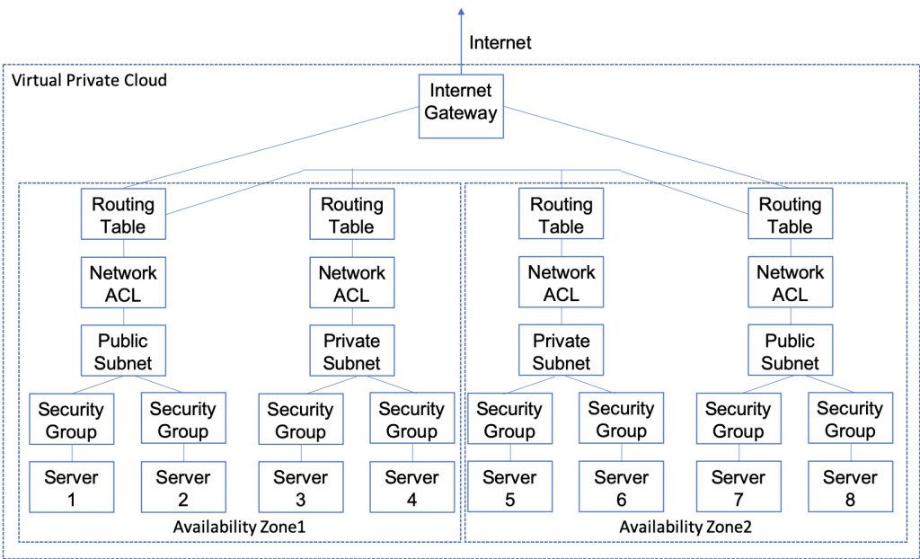
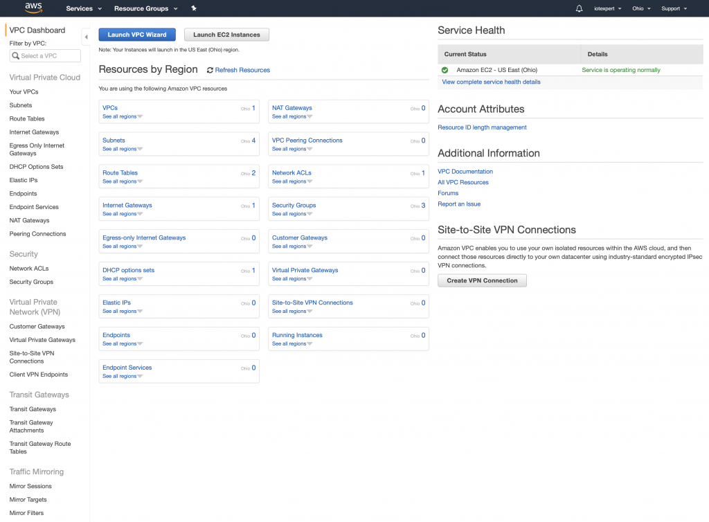
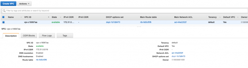
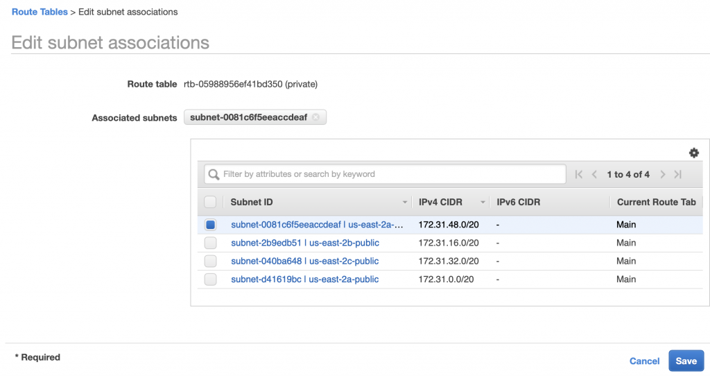
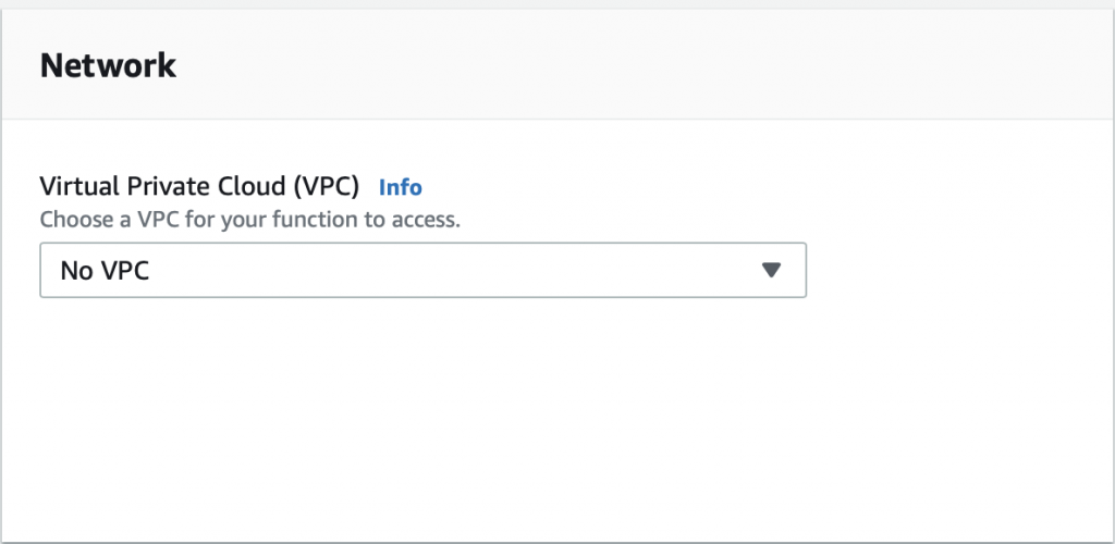
The problem is that the AWS Lambda Functions runs on the public Internet which does not have access to your AWS RDS database which you might recalls is on a private subnet in my VPC. To fix this, you need to tell AWS to run your function INSIDE of your VPC. Scroll down to the network section. See where it says “No VPC”
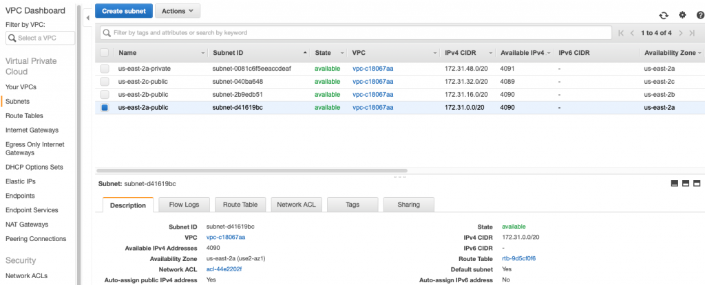
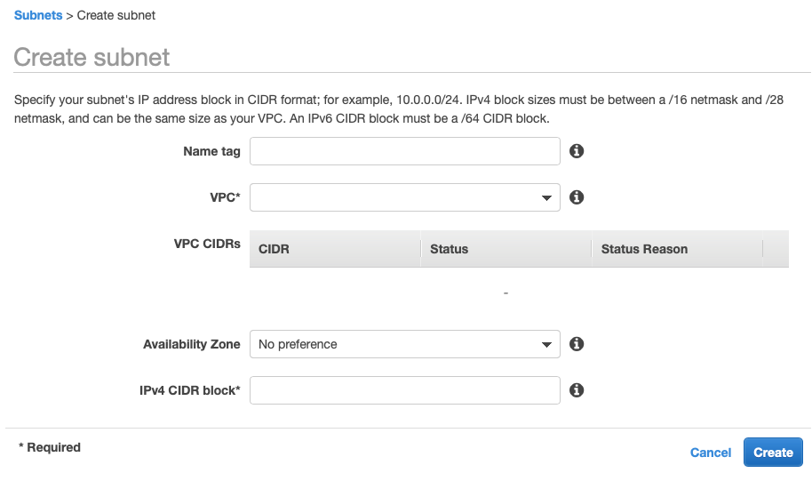
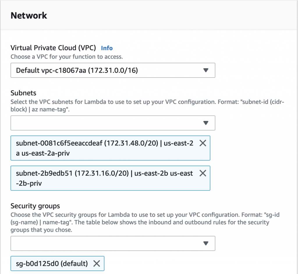
Pick out your VPC and then pick out two subnets in your VPC. You probably should pick two subnets from different availability zones. But it doesn’t matter if they are public or not as they only talk to the database.
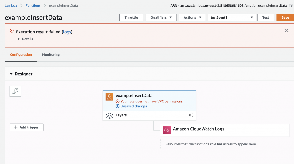
After clicking save I get this message “Your role does not have VPC permissions”. This took forever to figure out as well. To fix this problem, you need to create the correct IAM role….
Create an IAM Role and Assign to the Lambda Function
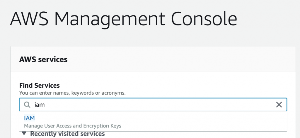
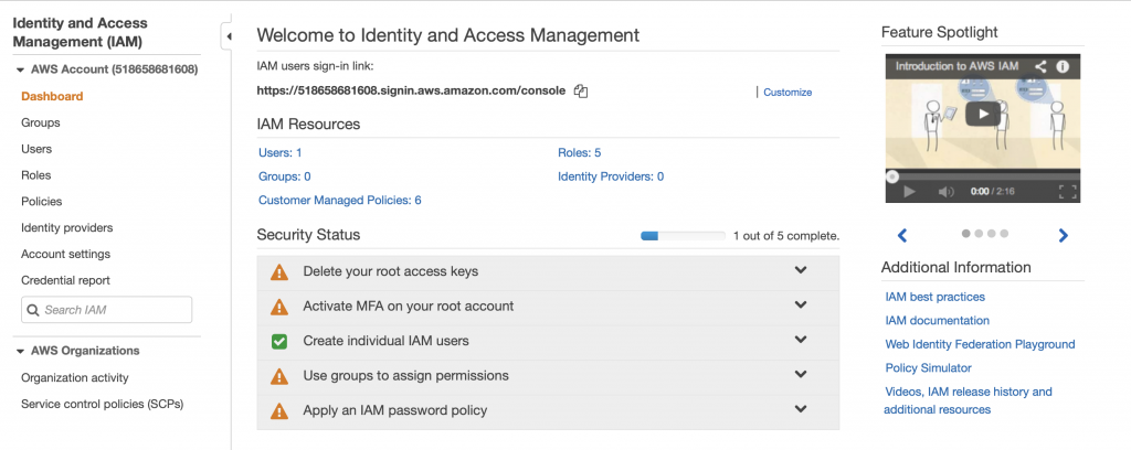
To create the role, you need to get to the IAM console and the “roles” sub console. There are several way to get to the screen to create the role. But I do this by going to the AWS console, searching for IAM, and clicking.
This takes me to the IAM Console. I don’t know that much about these options. Actually looking at this screen shot it looks like I have some “Security status” issues (which I will need to figure out). However in order to get the Lambda function to attach to your VPC, you need to create a role. Do this by clicking “Roles”
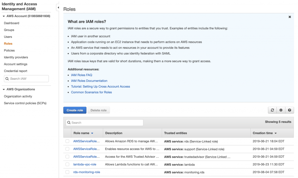
When you click on roles you can see that there are several roles, essentially rules that give your identity the ability to do things in the AWS cloud. There are some that are created by default. But in order for your Lambda function to attach to your VPC, you need to give it permission. To do this click “Create role”
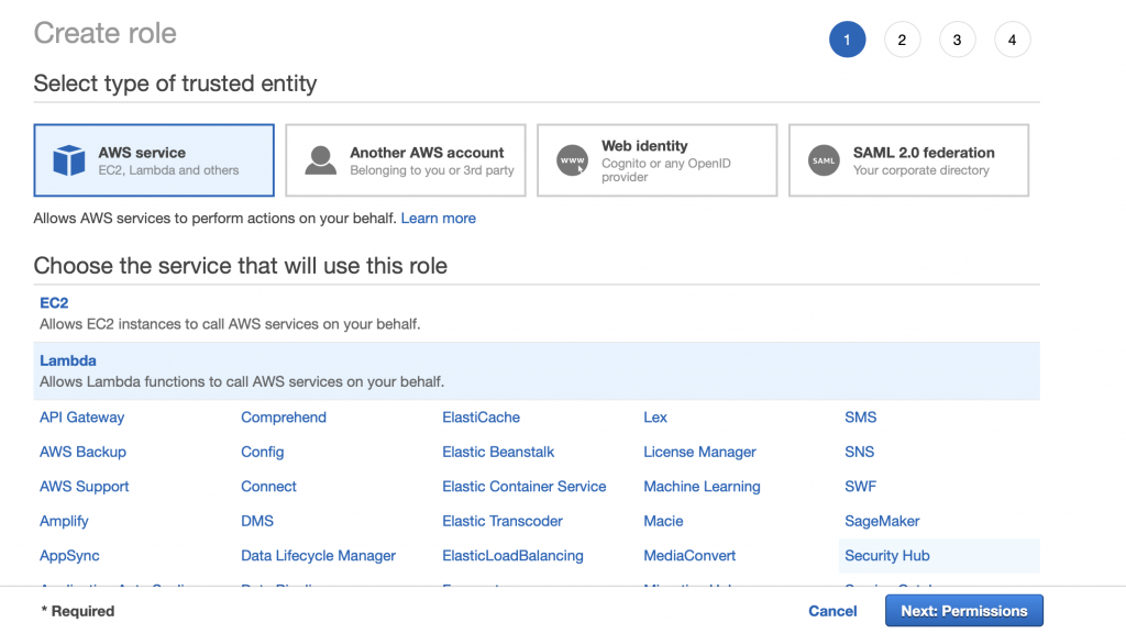
Pick “AWS service” and “Lambda” then click Next: Permissions
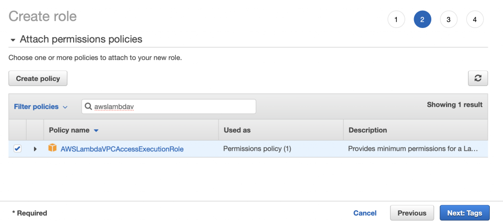
Search for the “AWSLambdaVPCAccessExecutionRole”. Pick it and then click Next: Tags
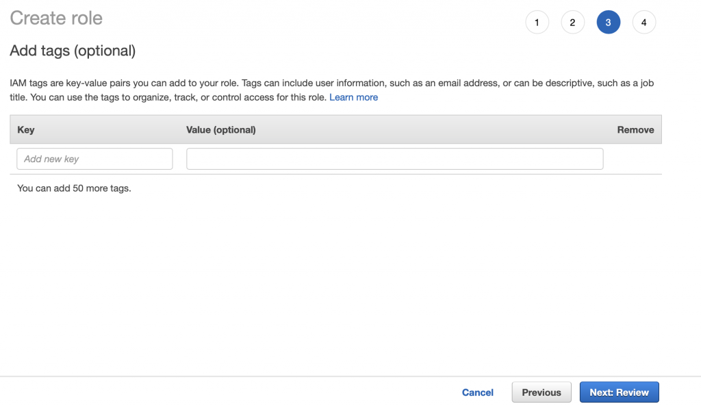
I don’t have any tags so click Next: Review
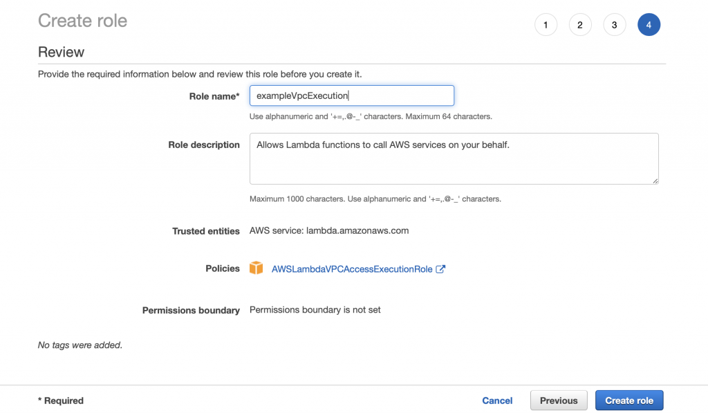
Give the role a name “exampleVpcExecution” then click Create role.
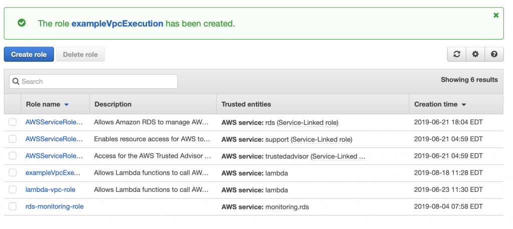
You should get a success message.
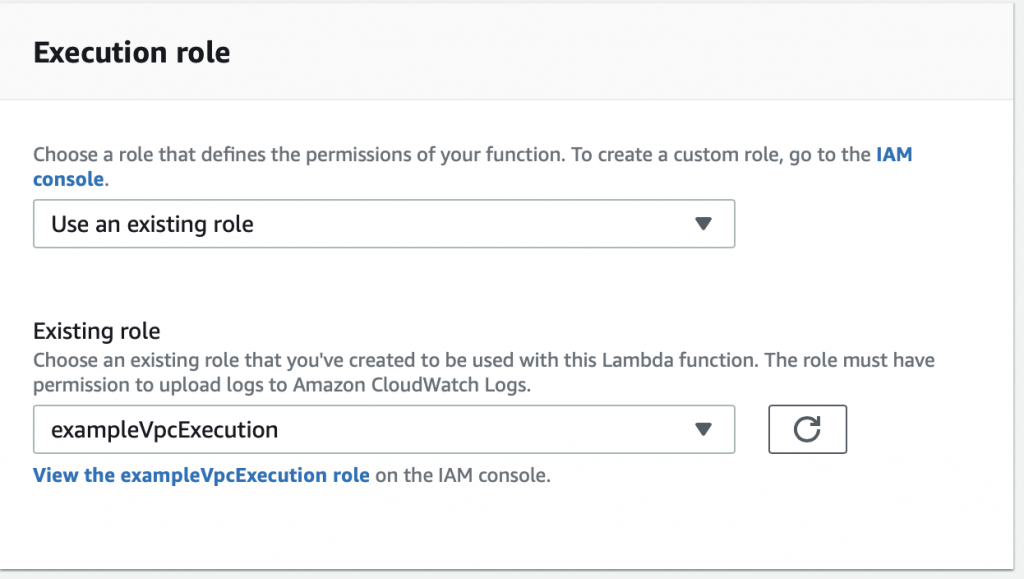
Now go back to the Lambda function configuration screen. Move down to “Execution role” and pick out the role that you just created.
Now when I test things work…. now let’s fix up the function to actually do the work of inserting data.
Update the Lambda Function to Insert Data
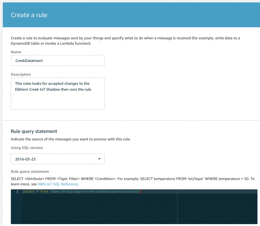
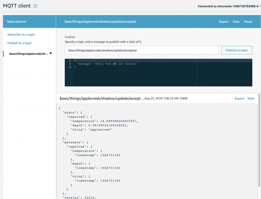
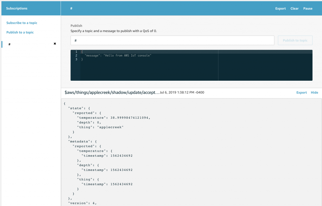
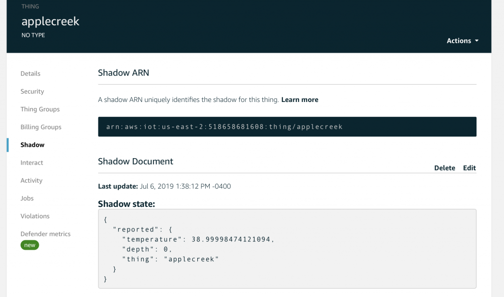
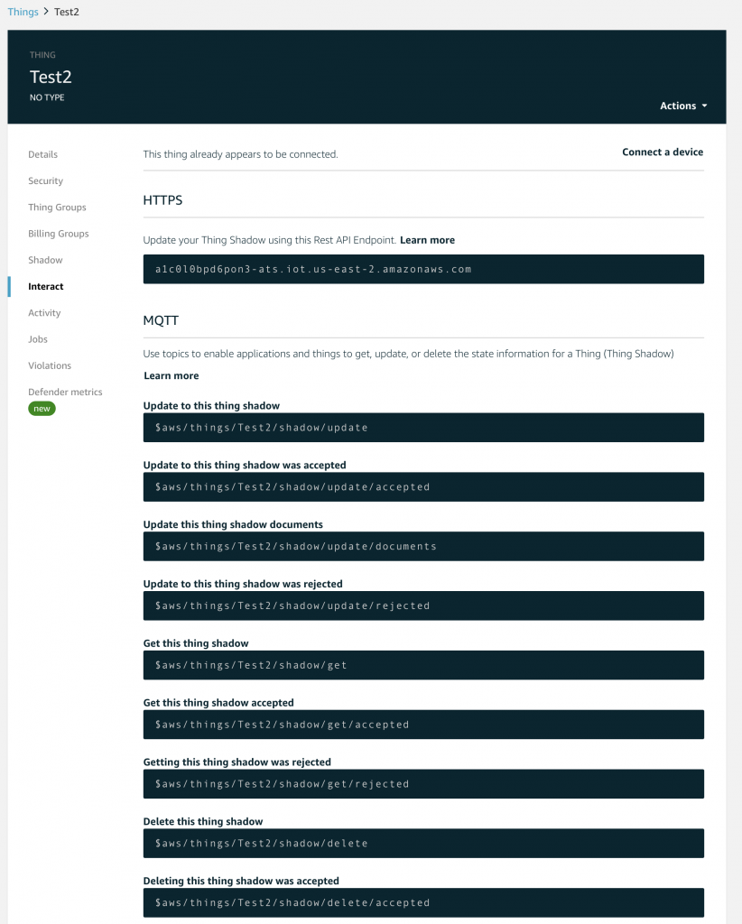
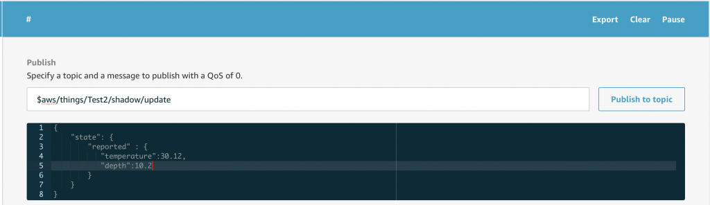
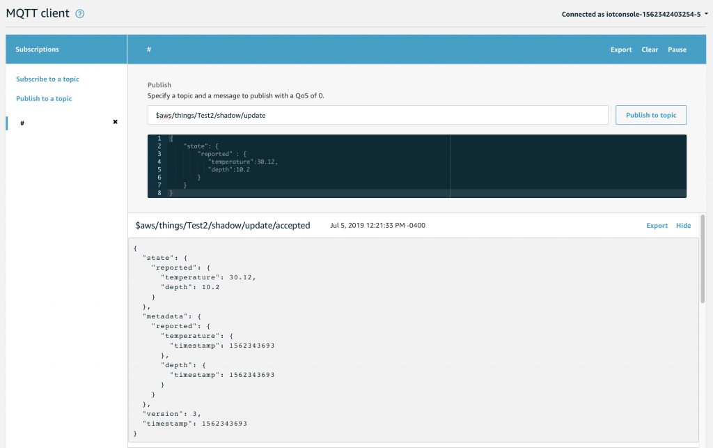
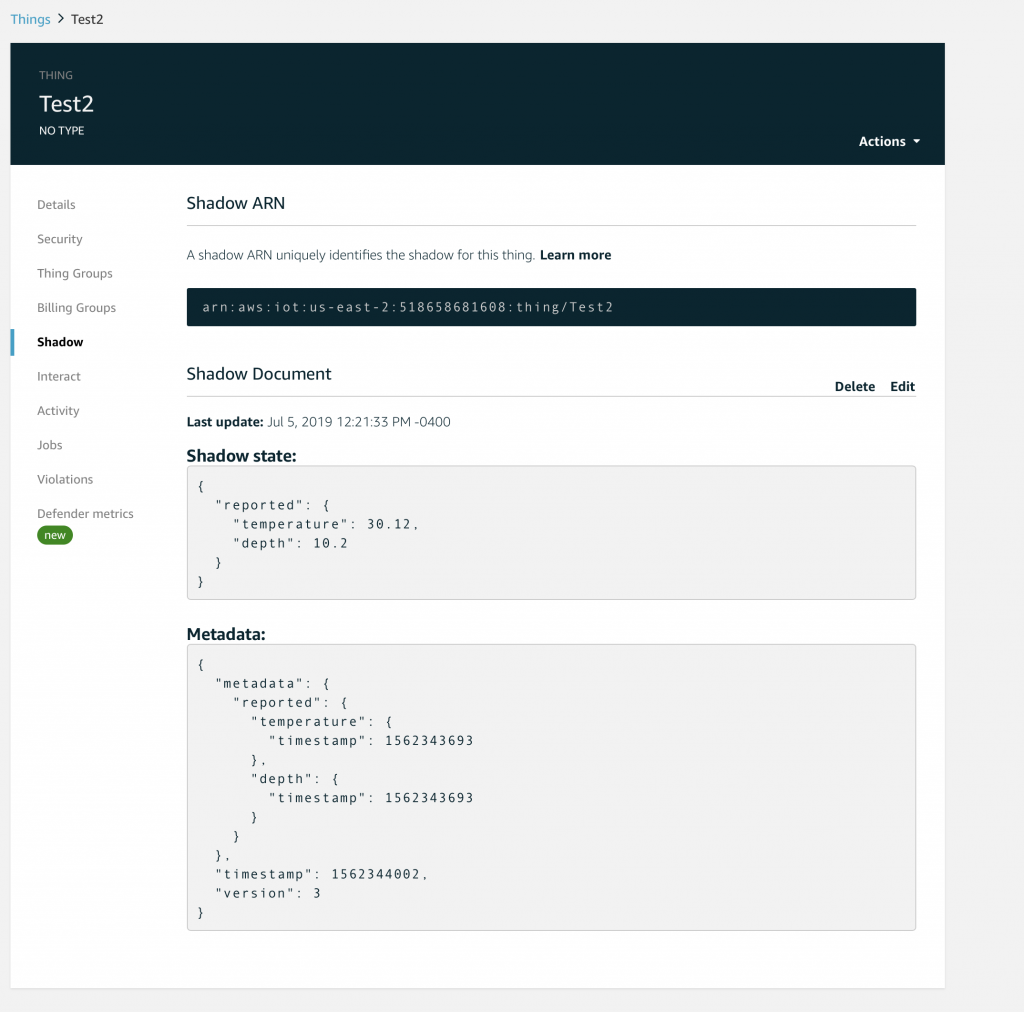
You should recall from the article on AWS MQTT that when you update the IoT Device Shadow via MQTT you publish a JSON message like this to the topic “$aws/things/applecreek/shadow/update”
{
  "state": {
    "reported": {
      "temperature": 37.39998245239258,
      "depth": 0.036337487399578094,
      "thing": "applecreek"
    }
  }
}
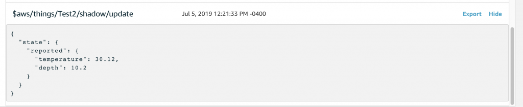
Which will cause the AWS IoT to update you device shadow and then publish a message to “$aws/things/applecreek/shadow/update/accepted” like this:
{
  "state": {
    "reported": {
      "temperature": 37.39998245239258,
      "depth": 0.036337487399578094,
      "thing": "applecreek"
    }
  },
  "metadata": {
    "reported": {
      "temperature": {
        "timestamp": 1566144733
      },
      "depth": {
        "timestamp": 1566144733
      },
      "thing": {
        "timestamp": 1566144733
      }
    }
  },
  "version": 27323,
  "timestamp": 1566144733
}
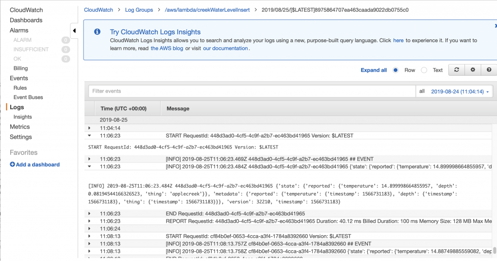
In the next article Im going to show you how to hook up those messages to run Lambda function. But, for now assume that the JSON that comes out of the “…/accepted” topic will be passed to your function as the “event”.
The program has the following sections:
- Setup the imports
- Define some Configuration Variables
- Make a logger
- Make a connection to the RDS database
- Find the name of the thing in the JSON message
- Search for the thingId in the table creekdata.things
- Find the state key/value
- Find the reported key/value
- Find the depth key/value
- Find the temperature key/value
- Find the timestamp key/value
- Convert the UTC timestamp to Eastern Time (I should have long ago designed this differently)
- Insert the new data point into the Database
Setup the Imports
The logging import is used to write data to the AWS logging console.
The pymysql is a library that knows how to attach to MySQL databases.
I made the decision years ago to store time in eastern standard time in my database. That turns out to have been a bad decision and I should have used UTC. Oh well. To remedy this problem I use the “pytz” to convert between UTC (what AWS uses) and EST (what my system uses)
import sys
sys.path.append("./package")
import logging
import pymysql

from pytz import timezone, common_timezones
import pytz
from datetime import datetime
Define Some Configuration Variables
Rather than hardcode the Keys in the JSON message, I setup a number of global variables to hold their definition.
stateKey ="state"
reportedKey = "reported"
depthKey = "depth"
temperatureKey = "temperature"
timeKey = "time"
deviceKey = "thing"
timeStampKey = "timestamp"
Make a connection to the RDS Database
In order to write data to my RDS MySQL database I create a connection using “pymysql.connect”. Notice that if this fails it will write into the cloud watch log. If it succeeds then there will be a global variable called “conn” with the connection object.
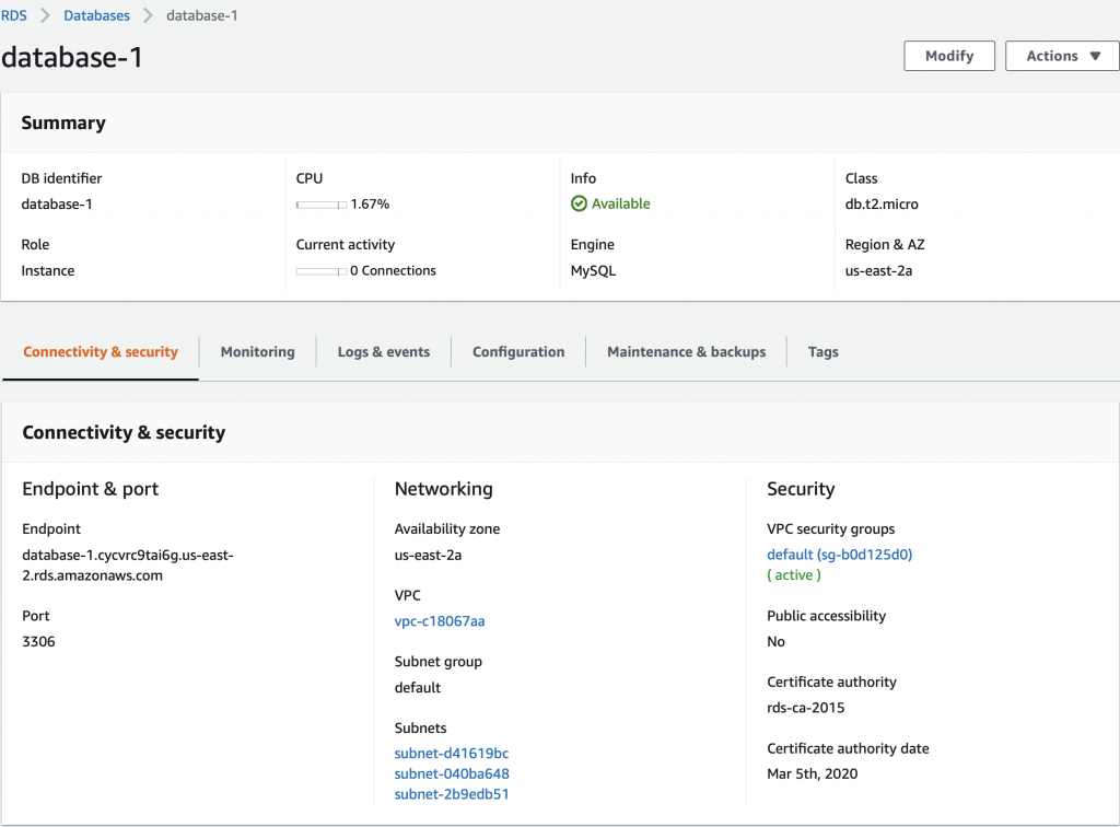
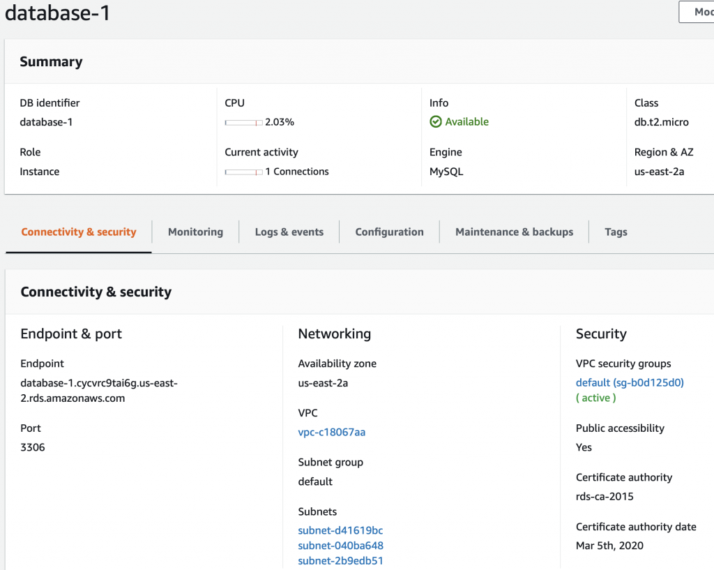
rds_host  = "creekdata.cycvrc9tai6g.us-east-2.rds.amazonaws.com"
name = "database user"
password = "databasepassword"
db_name = "creekdata"

try:
    conn = pymysql.connect(rds_host, user=name, passwd=password, db=db_name, connect_timeout=5)
except:
    logger.error("ERROR: Unexpected error: Could not connect to MySQL instance.")
    sys.exit()
Make a logger
AWS gives you the ability to write to the AWS CloudWatch logging system. In order to write there, you need to create a “logger”
logger = logging.getLogger()
logger.setLevel(logging.INFO)
Look for the stateKey and reportKey
The JSON message “should” have key called “state”. The value of that key is another keymap with a value called “reported”
if stateKey in event:
        if reportedKey in event[stateKey]:
Find the Depth
Assuming that you have state/reported then you need to find the value of the depth
if depthKey in event[stateKey][reportedKey]:
                depthValue = event[stateKey][reportedKey][depthKey]
Find the Temperature
It was my intent to send the temperature every time I update the shadow state. But I put in a provision for the temperature not being there and taking the value -99
if temperatureKey in event[stateKey][reportedKey]:
                temperatureValue = event[stateKey][reportedKey][temperatureKey]
            else:
                temperatureValue = -99
Look for a Timestamp
My current sensor system does not keep time, however, I may add that functionality at some point. So, I put in the ability to have a timeStamp set by the sensor. If there is no timestamp there, AWS happily makes one for you when you update the device shadow. I look in
- The reported state
- The overall message
- Or I barf
if timeStampKey in event[stateKey][reportedKey]:
                timeValue = datetime.fromtimestamp(event[stateKey][reportedKey][timeStampKey],tz=pytz.utc)
#                logger.info("Using state time")
            elif timeStampKey in event:
#                logger.info("using timestamp" + str(event[timeStampKey]))
                timeValue = datetime.fromtimestamp(event[timeStampKey],tz=pytz.utc)
            else:
                raise Exception("JSON Missing time date")
Find the name of the thing in the JSON message
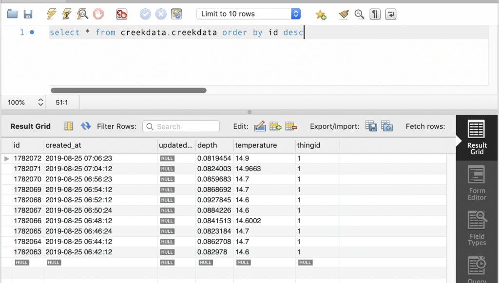
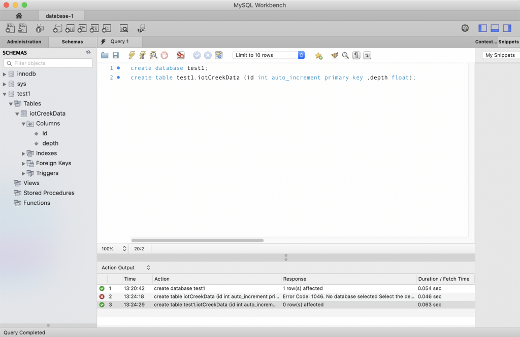
My database has two tables. The table called “creekdata” has columns of id, thingid, depth, temperature, created_at. The thing id is key into another table called “things” which has the columns of thingid and name. In other words, it has a map of a text name for things to a int value. This lets me store multiple thing values in the same creekdata table… which turns out to be an overkill as I only have one sensor.
When I started working on this program I wanted the name of thing to be added automatically as part of the JSON message, but I couldn’t figure it out. So, I added the thing name as a field which is put in by the sensor.
if deviceKey in event[stateKey][reportedKey]:
                deviceValue = event[stateKey][reportedKey][deviceKey]
            else:
                logger.error("JSON Event missing " + deviceKey)
                raise Exception("JSON Event missing " + deviceKey)
Search for the thingId in the table creekdata.things
I wrote a function which takes the name of a thing and returns the thingId.
def getThingId(deviceName):
    with conn.cursor() as cur:
        cur.execute("select thingid from creekdata.things where name=%s", deviceName)
    results = cur.fetchall()
#    logger.info("Row = " + str(len(results)))
    if len(results) > 0:
#        logger.info("thingid = "+ str(results[0][0]))
        return results[0][0]
    else:
        raise Exception("Device Name Not Found " + deviceName)
Convert the UTC timestamp to Eastern Time
As I pointed out earlier, I should have switched the whole system to store UTC. But no. So I use the pytz function to switch my UTC value to EST.
  tz1 = pytz.timezone('US/Eastern')
    xc = timeValue.astimezone(tz1)
Insert the New Data Point into the Database
Now we know everything, so insert it into the database.
with conn.cursor() as cur:
        cur.execute("INSERT into creekdata.creekdata (created_at,depth, thingid,temperature) values (%s,%s,%s,%s)",(xc.strftime("%Y-%m-%d %H:%M:%S"),depthValue,thingIdValue,temperatureValue));
    conn.commit()
The Final Program
Here is the whole program in one place.
import json
import sys
import logging
import os

sys.path.append("./package")
import pymysql

from pytz import timezone, common_timezones
import pytz
from datetime import datetime

stateKey ="state"
reportedKey = "reported"
depthKey = "depth"
temperatureKey = "temperature"
timeKey = "time"
deviceKey = "thing"
timeStampKey = "timestamp"

#rds settings
rds_host  = "put your endpoint here.us-east-2.rds.amazonaws.com"
name = "mysecretuser"
password = "mysecretpassword"
db_name = "creekdata"

logger = logging.getLogger()
logger.setLevel(logging.INFO)

try:
    conn = pymysql.connect(rds_host, user=name, passwd=password, db=db_name, connect_timeout=5)
except:
    logger.error("ERROR: Unexpected error: Could not connect to MySQL instance.")
    sys.exit()


def lambda_handler(event,context):
    logger.info('## EVENT')
    logger.info(event)
    insertVal = ""
    if stateKey in event:
        if reportedKey in event[stateKey]:
            if depthKey in event[stateKey][reportedKey]:
                depthValue = event[stateKey][reportedKey][depthKey]
            if temperatureKey in event[stateKey][reportedKey]:
                temperatureValue = event[stateKey][reportedKey][temperatureKey]
            else:
                temperatureValue = -99
            if timeStampKey in event[stateKey][reportedKey]:
                timeValue = datetime.fromtimestamp(event[stateKey][reportedKey][timeStampKey],tz=pytz.utc)
#                logger.info("Using state time")
            elif timeStampKey in event:
#                logger.info("using timestamp" + str(event[timeStampKey]))
                timeValue = datetime.fromtimestamp(event[timeStampKey],tz=pytz.utc)
            else:
                raise Exception("JSON Missing time date")

            if deviceKey in event[stateKey][reportedKey]:
                deviceValue = event[stateKey][reportedKey][deviceKey]
            else:
                logger.error("JSON Event missing " + deviceKey)
                raise Exception("JSON Event missing " + deviceKey)
        else:
            raise Exception("JSON Event missing " + reportedKey)
    else:
        raise Exception("JSON Event missing " + stateKey)

    thingIdValue = getThingId(deviceValue)
    tz1 = pytz.timezone('US/Eastern')
    xc = timeValue.astimezone(tz1)

    with conn.cursor() as cur:
        cur.execute("INSERT into creekdata.creekdata (created_at,depth, thingid,temperature) values (%s,%s,%s,%s)",(xc.strftime("%Y-%m-%d %H:%M:%S"),depthValue,thingIdValue,temperatureValue));
    conn.commit()

    return "return value"  # Echo back the first key value

def getThingId(deviceName):
    with conn.cursor() as cur:
        cur.execute("select thingid from creekdata.things where name=%s", deviceName)
    results = cur.fetchall()
#    logger.info("Row = " + str(len(results)))
    if len(results) > 0:
#        logger.info("thingid = "+ str(results[0][0]))
        return results[0][0]
    else:
        raise Exception("Device Name Not Found " + deviceName)