Electronica 2016 – The WICED Server

The last three days at Electronica I have been showing people how to build the Robot ARM Controller.  In previous posts I talked about the process for the Servo Motor controller and the CapSense user interface.

image009

In this post I am going to focus on the TCP/IP Server running on the Cypress WICED board.  Remember that this board performs two functions

  1. An I2C Master which writes data to the PSoC Servo Motor Controller
  2. A TCP/IP Server listening on TCP Port 40508.  The command format of the TCP/IP Packet is a 2-digit ASCII coded hex number representing the position of motor 1 followed by a 2-digit ASCII coded hex number for motor 2 e.g 3240 takes motor 1 to 0x32 aka 50% and 0x40 aka 64% for motor 2

The first section of code (lines 11-14) gets things going by starting WICED and attaching to the network.  The next section (lines 16-26) sets up the I2C Master and creates a standard message buffer (called tx_buffer).  Finally on lines 28-30 creates a socket and starts listening to TCP/IP Port 40508.

screen-shot-2016-11-11-at-7-30-38-am

The main loop of my server starts by waiting for a valid active connection (line 34-36).  Then when it gets a valid connection it

  • Line 43: receives the data into a packet
  • Line 45: gets a pointer (rbuffer) to the data in the packet
  • Line 46: translates the ASCII data into integers
  • Line 50: frees the tcp pack
  • Line 52: sends the updated position to the PSoC via I2C

screen-shot-2016-11-11-at-7-35-08-am

All of this source code is posted to the iotexpert GitHub site at git@github.com:iotexpert/E2016RobotArm.git

Electronica 2016 – CY8CKIT-145 User Interface

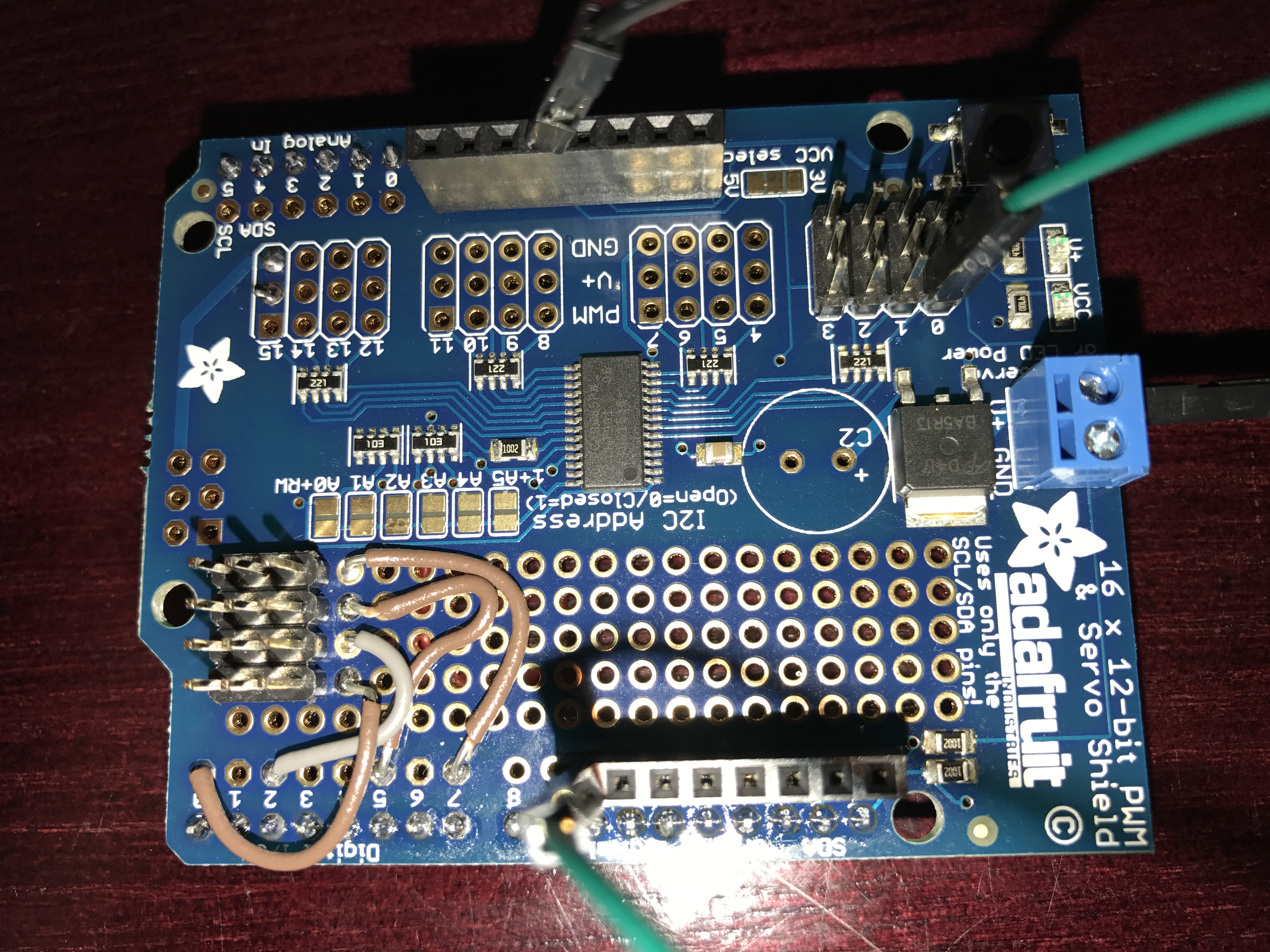
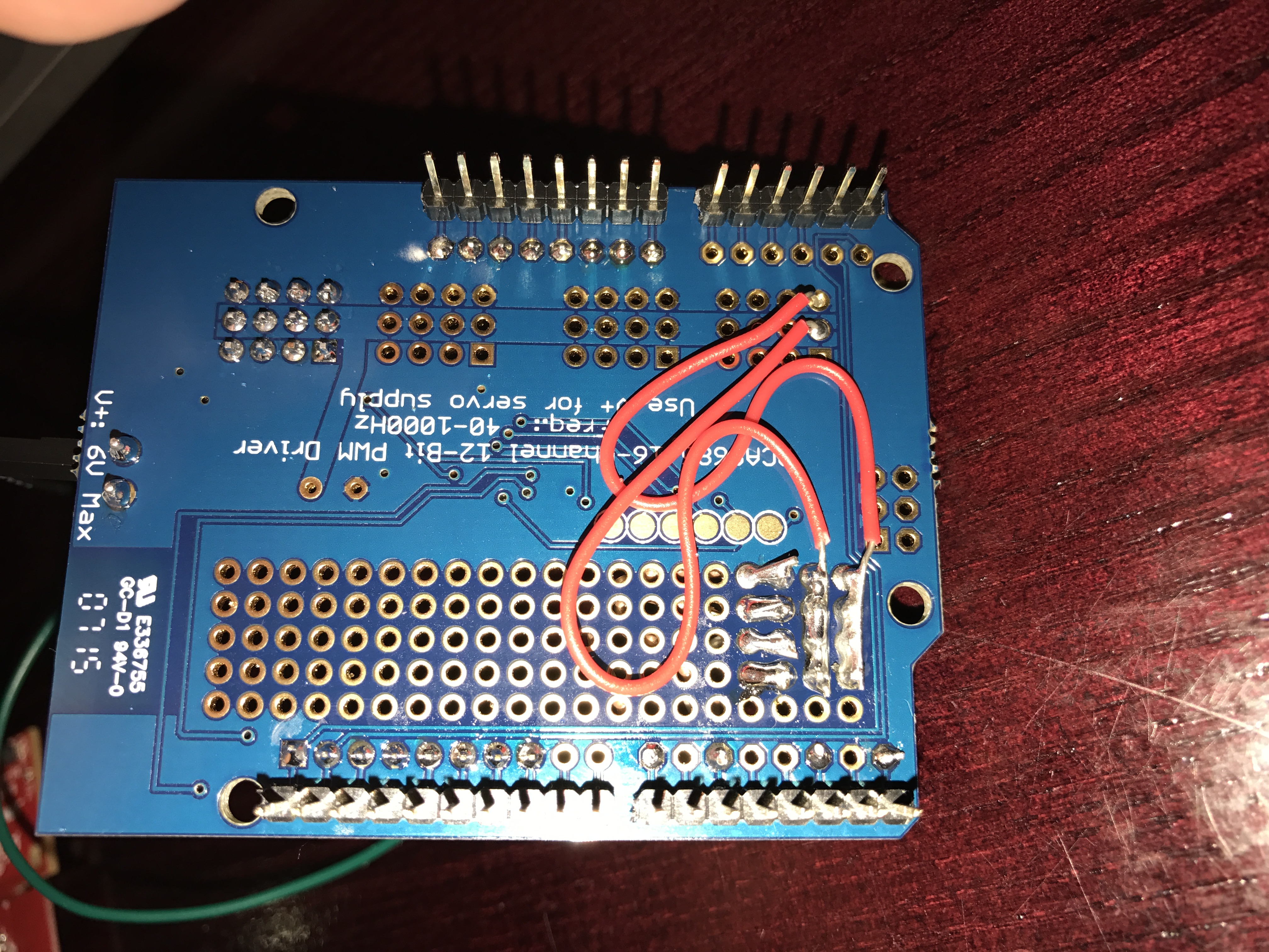
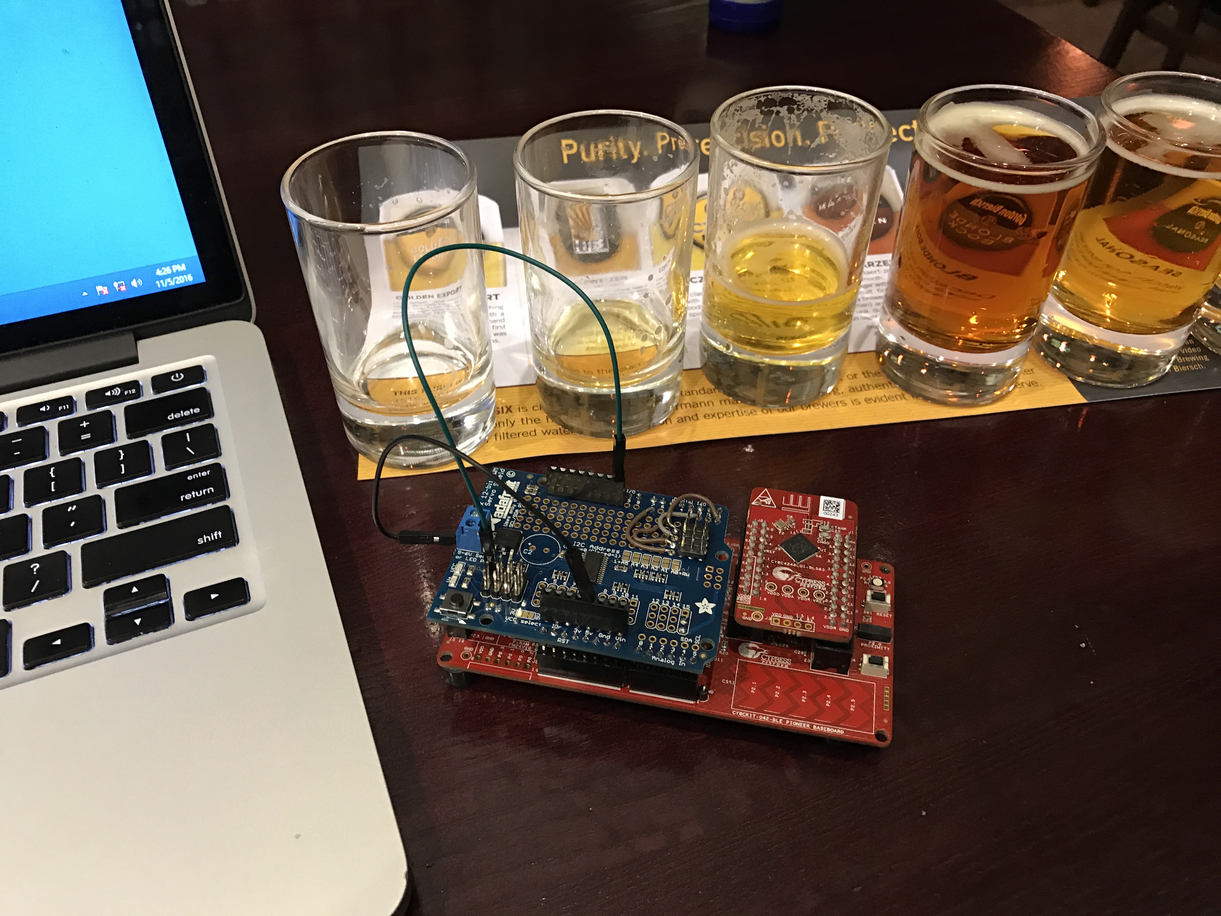
I finally made it to Munich late yesterday afternoon… then I proceeded to turn my hotel room into an electronics lab as I frantically worked to finish everything for tomorrow.  Earlier this year I wrote a whole series of posts about the PSoC4000S & CY8CKIT-145 after the Embedded World show.  We finally have volume production on the development kit and will be giving them out at the show this week.  So, I decided to use the -145 as part of the user interface for my Electronica project.  The devkit functions as the block labeled “PSoC Capsense”.  The wire between the “PSoC Capsense” and the “WICED WiFi” will be I2C (the green and red wire from the picture below)

electronica-wiced

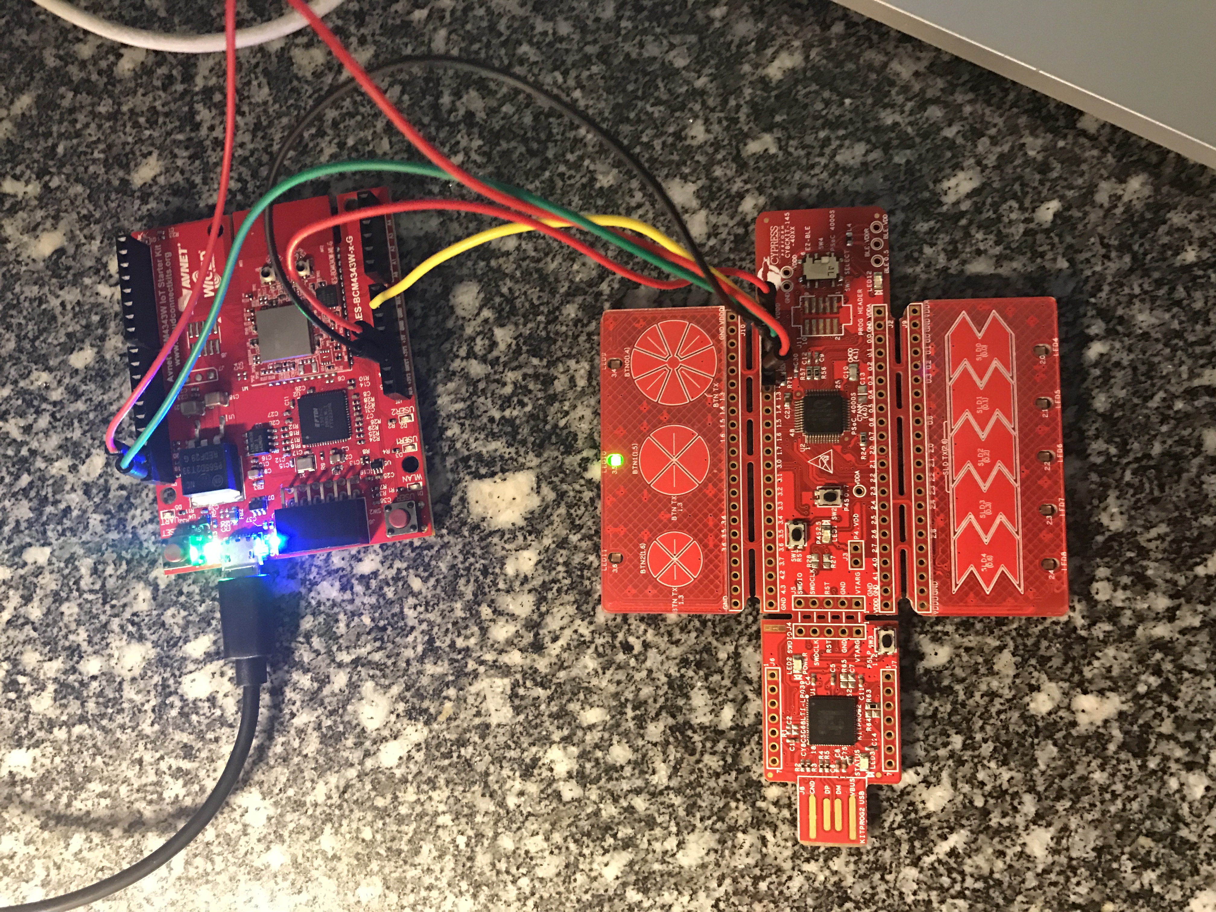
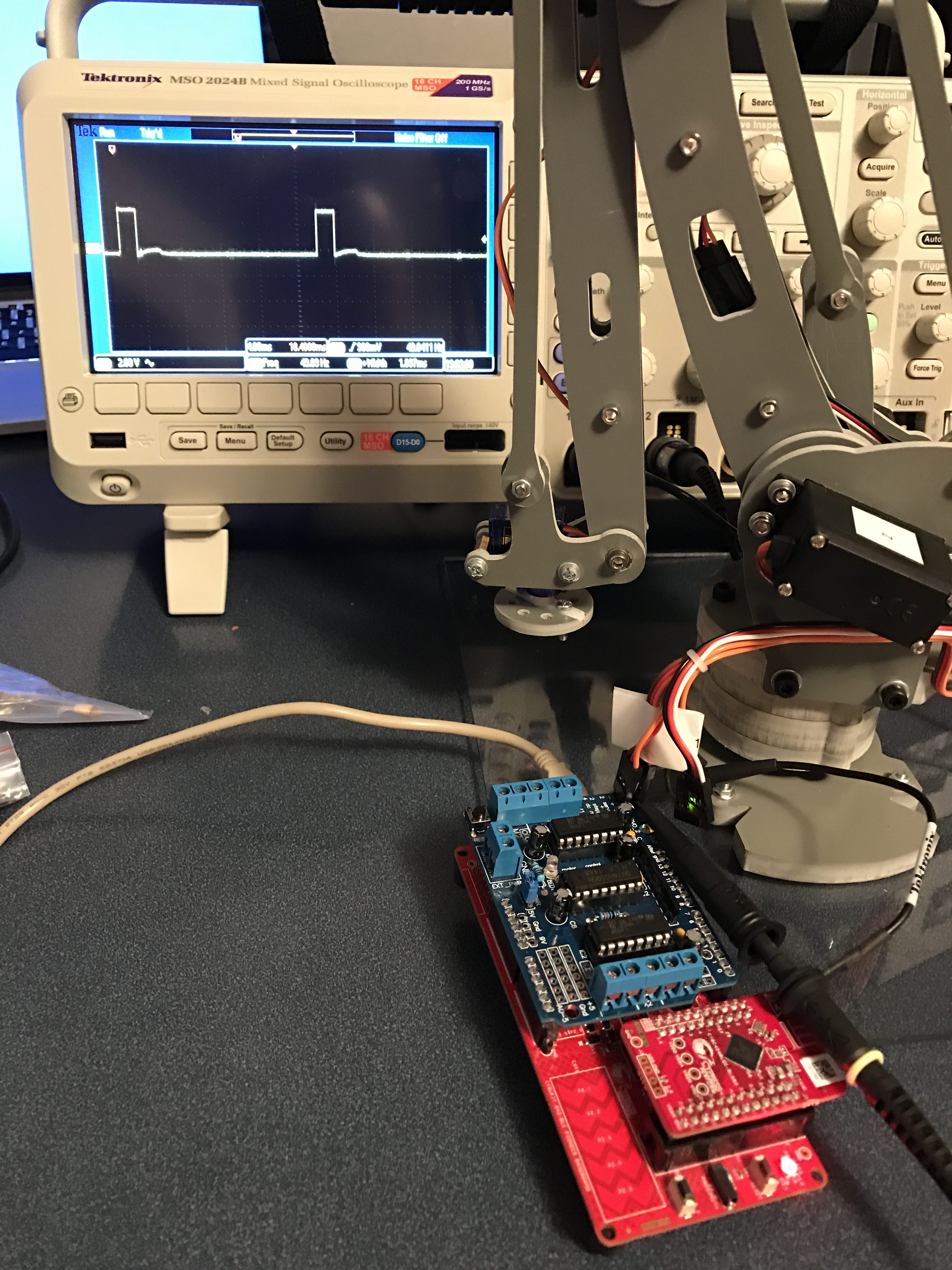
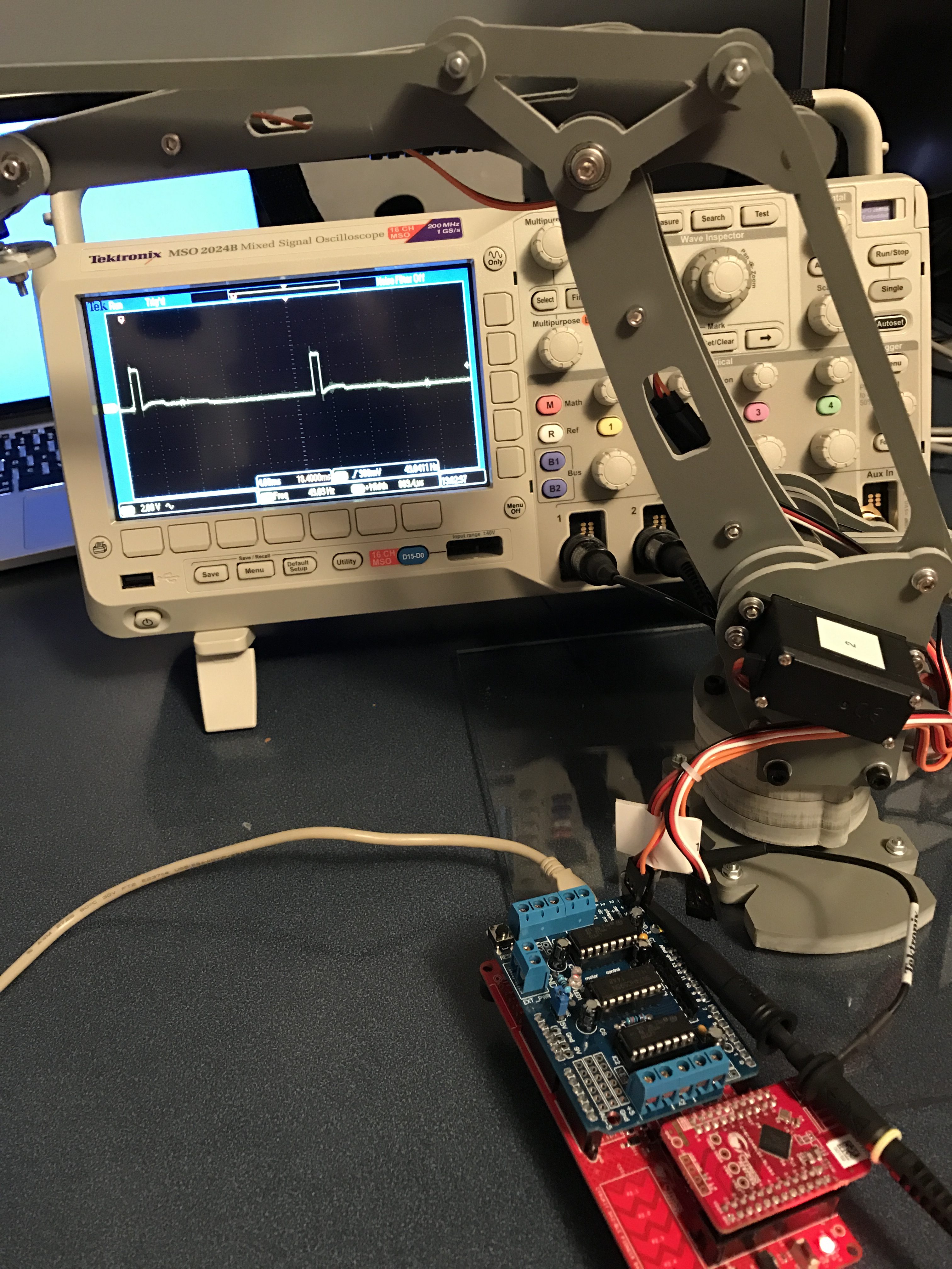
The -145 devkit has the PSoC4000S silicon on it which has the new mutual capacitance capsense block.  On the devkit, there are three mutual cap buttons and one slider.  Here is a picture of the devkit connected to the WICED WiFi board that I am going to use:

img_3318

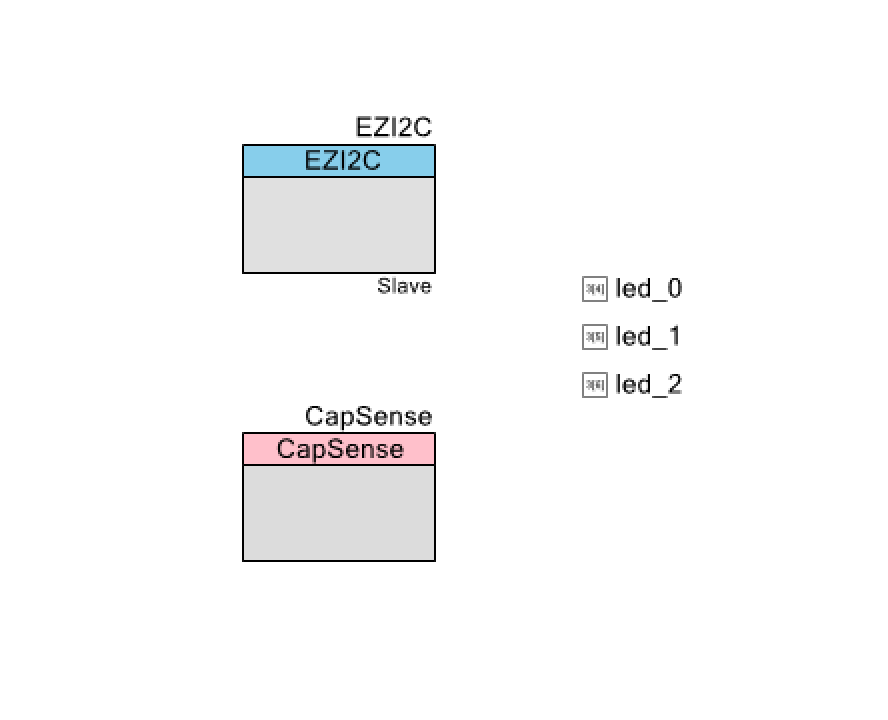
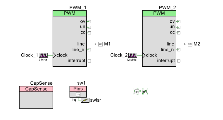
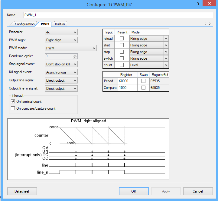
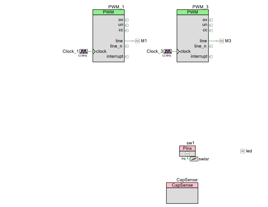
I want to make as simple of a PSoC Creator project as I can possibly do as I want to be able to easily do it live.  Here it is:

screen-shot-2016-11-07-at-10-12-23-am

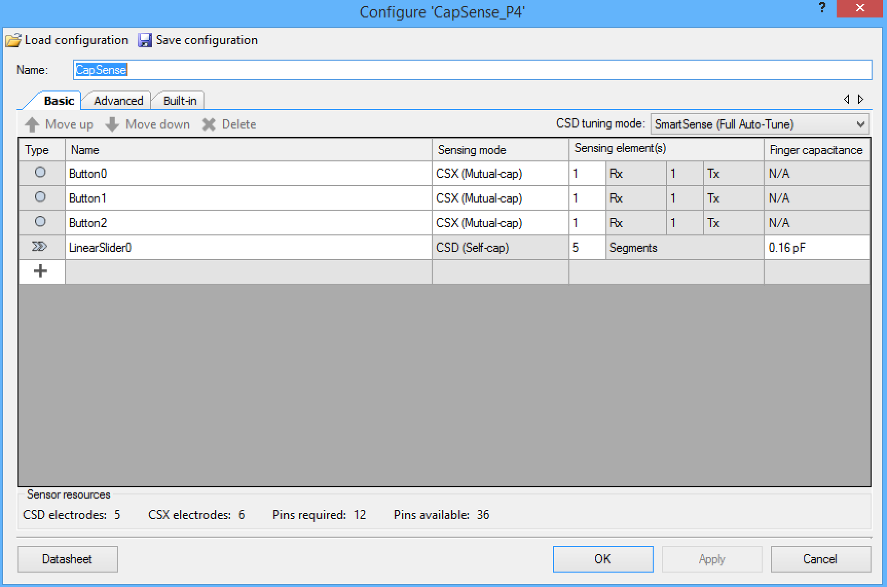
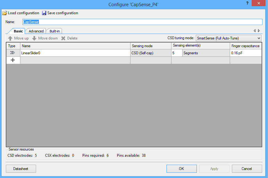
The CapSense block is configured with three mutual cap buttons and 1 self-cap slider:

screen-shot-2016-11-07-at-10-13-54-am

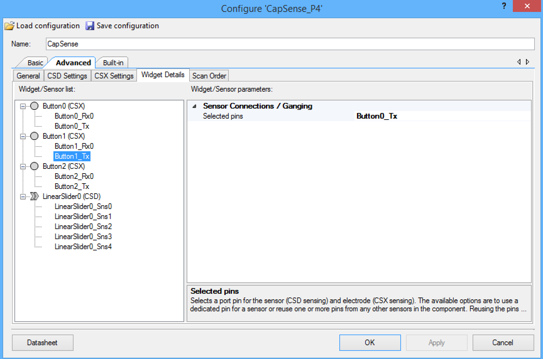
On this development board, the three mutual cap buttons share the same transmit line, so you need to configure the component that way. The screen shot below shows the configuration of the “Button1_Tx” which is set to share the “Button0_Tx”.  You need to make the same setting for “Button2_Tx”.

screen-shot-2016-11-07-at-10-15-34-am

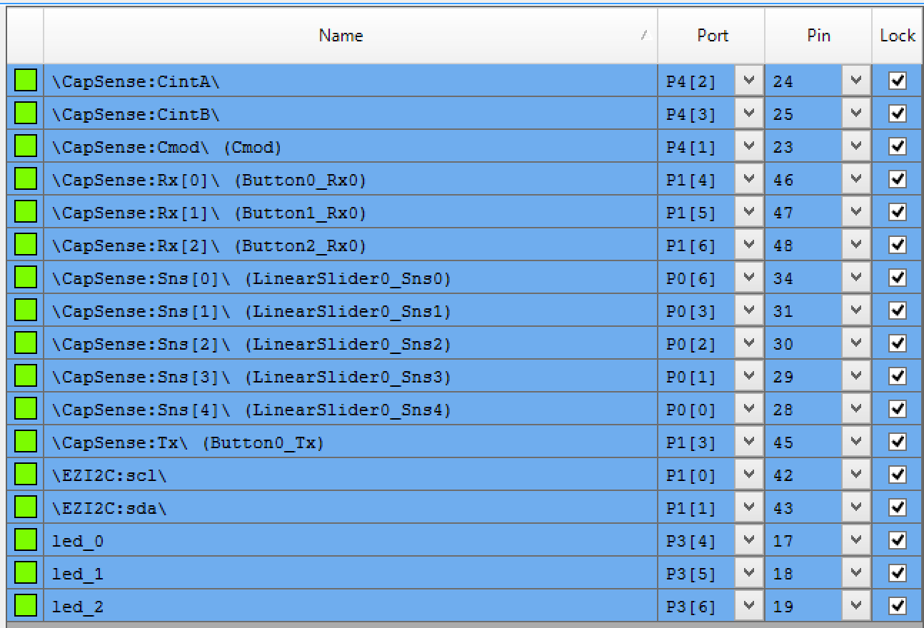
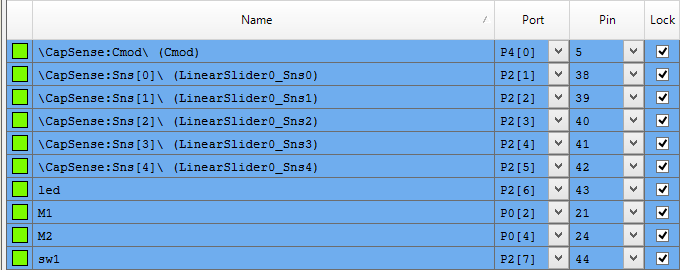
The next step is to assign all of the pins to the proper locations:

screen-shot-2016-11-07-at-10-18-10-am

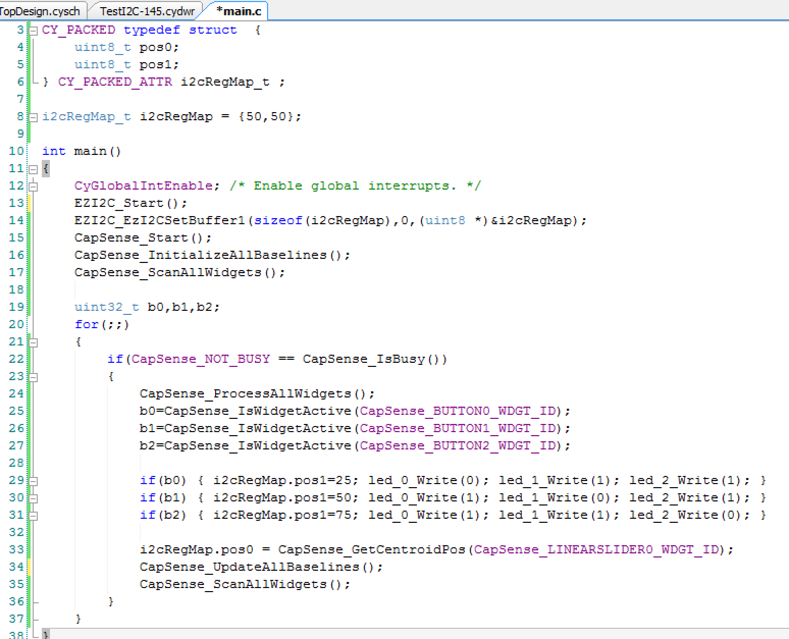
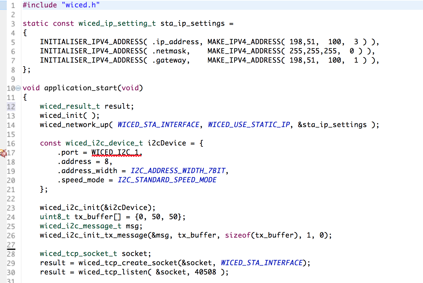
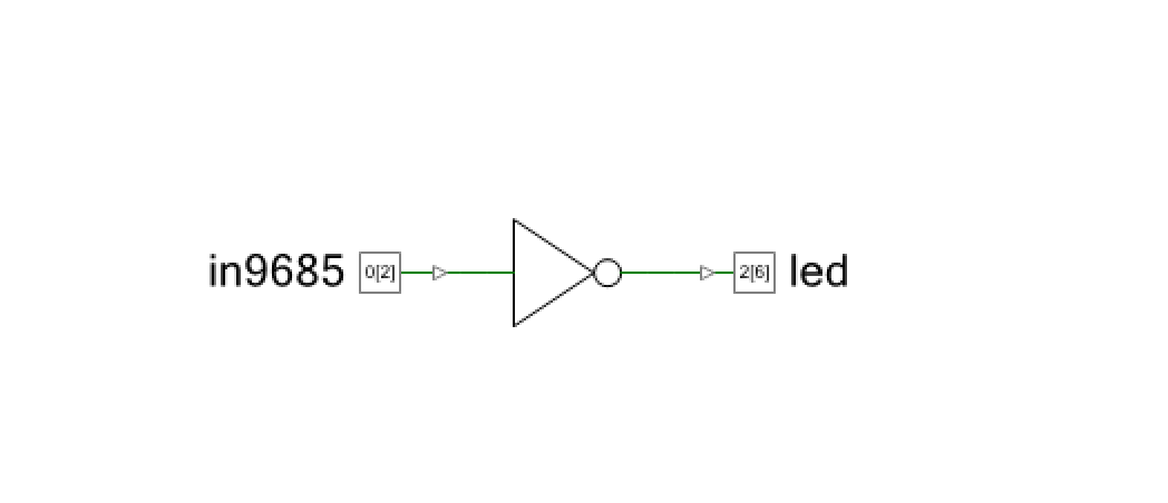
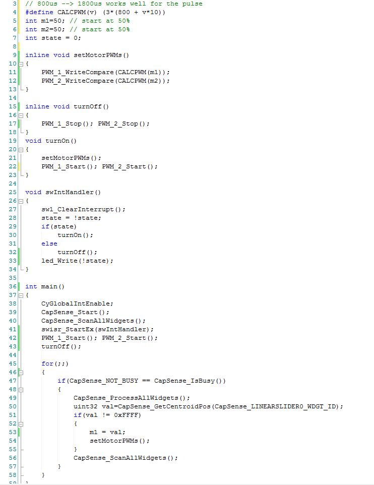
Finally the smallest amount of firmware that I could think up to hold it all together.

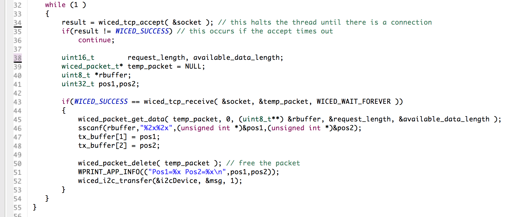
Line 3-6: define a structure that the WICED board will be able to read.  It will represent the position of two of the Servo motors.  The CY_PACKED provides the compiler appropriate key words to make the bytes be right next to each other in the RAM, i.e. not word aligned..

Line 8: initializes both positions to 50%.

Lines 12-17 get the components going

Line 22: Checks to make sure that the CapSense block is not scanning before it reads the results

Line 24: Tells the CapSense block to process the results from the previous scan

Lines 25-31: Looks at the three buttons, sets the LEDs and sets pos1 to be either 25%, 50% or 75%

Line 33: Reads the position of the slider and assigns it to “pos0”

Lines 34-35: Gets the scanning going again

screen-shot-2016-11-07-at-10-21-02-am

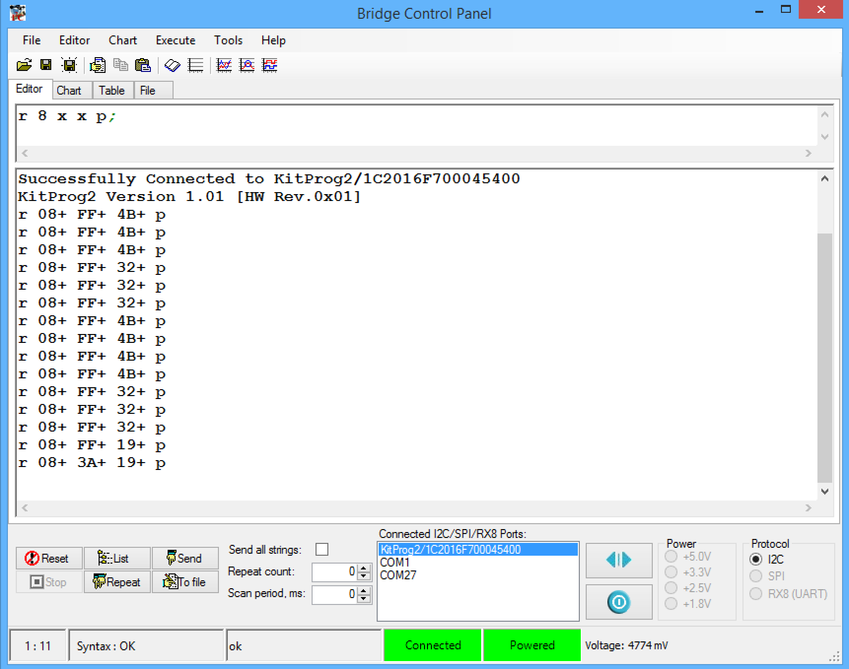
To test the system I first used the bridge control panel.  First, connect to the kitprog2.  Then I setup a read from the I2C address (0x08) which is the address of my board.  I then click repeat which runs the read command over and over again.  In the picture below you can see that I tested the three position of the button (25,50 and 75 which are also known as 0x19, 0x32 and 0x4B).  Then I tested the slider by touching it about in the middle (0x3A)

screen-shot-2016-11-07-at-10-31-52-am

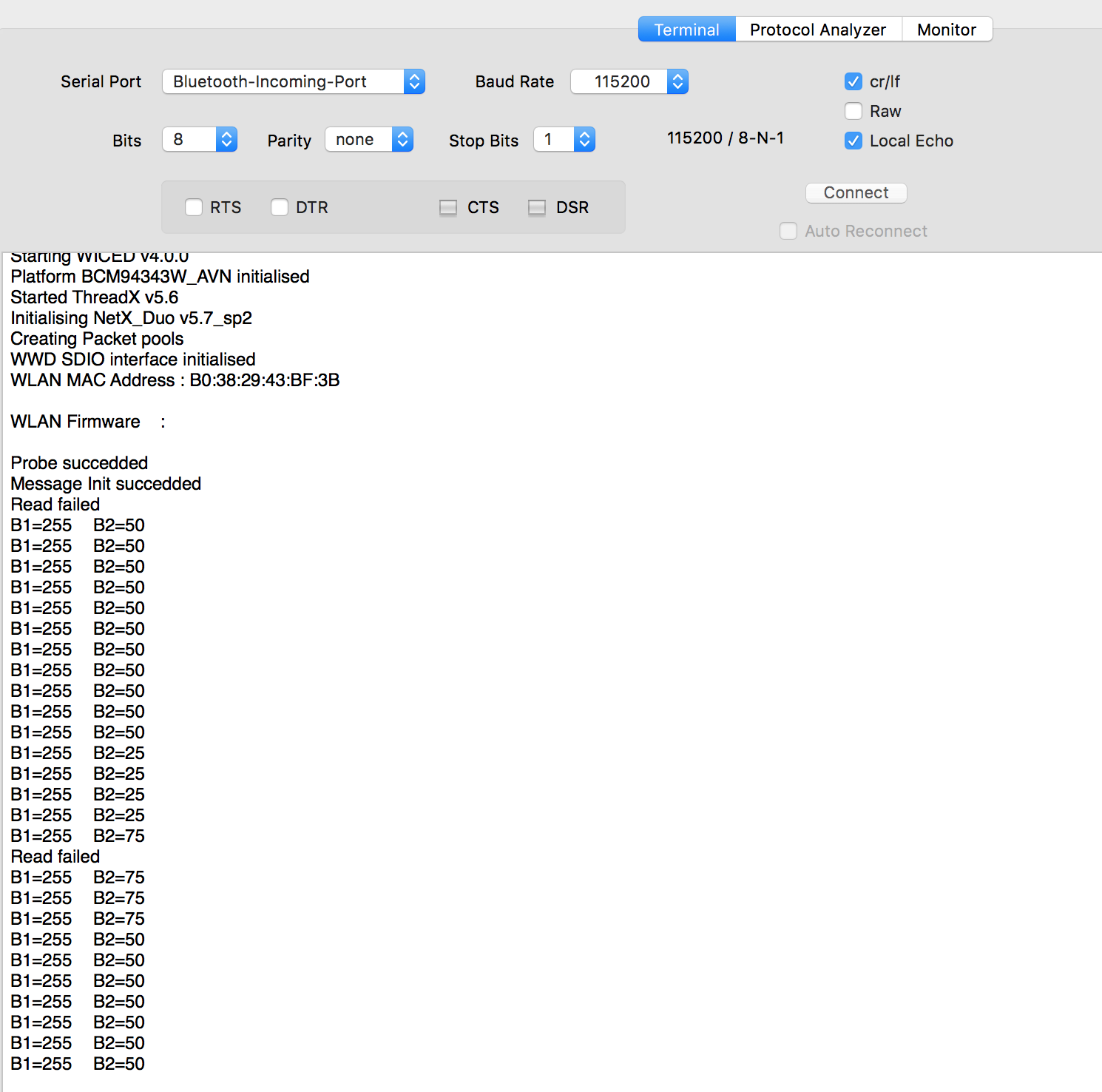
The next thing to do was make sure that the WICED devkit could read my I2C slave, so I wrote some WICED firmware to read the I2C registers every 500ms:

screen-shot-2016-11-07-at-10-55-08-am

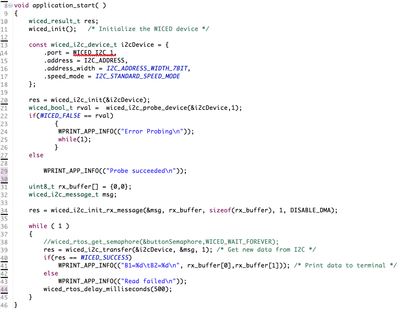
But, occasionally I  was getting a “read failed”:

screen-shot-2016-11-07-at-10-58-48-am

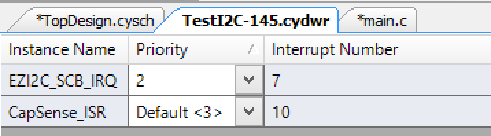
Last night in my sleep deprived state I was struggling like crazy to figure it out.  This morning after some sleep I realized that the WICED board that I have must not like getting its I2C clock stretched.  So, I changed the priority of the I2C interrupt on the PSoC and that fixed the problem:

screen-shot-2016-11-07-at-10-28-03-am

Keep watching here for more updates on the project.

Electronica 2016 – Servo Motor PWMs

As I talked about in my previous post I am going to use a PSoC as a servo motor controller as well as a CapSense UI.  The problem is that I wanted a really easy way to plug the servo motors into the PSoC.  It seems like all of the servos have a 3 wire interface, Power, Ground and PWM.  Here is a picture that I got from Adafruit’s website.

155-01

I was originally hoping that I could connect that servo directly to the PSoC, drive a ‘1’ to the power and a ‘0’ to the ground and PWM to the third input.  But, it turns out that these things suck some serious juice (100+ma?) so driving the power with the PSoC isn’t in the cards.  Given them amount of time that I had left, there was not time for a custom board, so I was in the situation of using a breadboard with wires all over the place which is ugly and a bit of a pain.  However, on Thursday I thought that I might find a “Servo Shield” and sure enough there are a number of them out there including this one which I got from Adafruit.  The problem is this shield uses a 16 channel I2C –> PWM driver from NXP.  I am not a fan of doing things with peripheral chips that PSoC can do for itself.  But, when I got the shield this morning in the mail there was a cool prototyping area on the shield.  So, I made my own header for connecting to the PSoC.  Here is the front:

img_3309

And here is the back:

img_3308

You can see that I shorted the whole row of ground together with a big blog of solder and wire.  I did the same thing with the power (the middle row).  Then I made a wire from each of the 4 PWMs pins to a good place on the PSoC (which I could drive the pins directly from one of the TCPWMs)

img_3300

The board worked great on my bench.  The only thing that I have done which is VERY questionable is that I wired the power supply for the system directly to the V5.0 aka VBUS… which I suppose will get me through the conference, but is probably a bad idea (the green wire in the top picture)

As I was flying to Detroit I thought that I might try to see how the I2C->PWM worked… so I read the data sheet for the NXP PCA9685.  It turns out that the chip is pretty cool.  You can set the output frequency by setting a divider value in one of the registers (oxFE).  The number you set is val=round(25e6/(4096*rate)) – 1.  That means for me to get 50hz to drive the motors I need to set the divider to 121.  Then to set the duty cycle each output has a 12-bit PWM where you can set “LED ON” and a “LED Off” count.  For instance to get a 25% duty cycle you can set the On to 0 and the off to 1024.

After I got off the airplane in Detroit I went to get some “dinner” and I wanted to try out the shield so I hooked it up:

img_3304

You always get a bunch of funny looks in the airport when your table looks like this:

img_3310This left me with only one problem.  How to drive the shield PWMs onto something that I could see… I didnt pack my Tek in my carry on (though I suppose I could have used one of those little scopes).  But, I digress.  What I decided to do is make the PSoC echo an input onto on output pin that was connected to an LED.  So, I drew this schematic.  This can only be done in with a PSoC because I used a logic gate in the UDB to flip the 9685 PWM from Low to High so that my active low LED would work right.

screen-shot-2016-11-05-at-8-02-36-pm

Next I fly to Charles De Gaul, the suckiest airport in the first world.  What will I do on the airplane there?  I don’t, but given those empty beer glasses I may sleep.  More to follow when I get to Germany.

Electronica + WICED + The Robot Arm

The good news is that the Robot Arm arrived from Amazon, which I was very happy about because it was a day late.  The even better news is that it works like a charm.  First I needed to assemble it, which I did with a little bit of help from my able lab technician and a trip to Lowe’s to get a base.

img_0003

Then “we” attached the base to the Robot.

img_0008

After the robot arm was put together on the base, I needed a little bit of firmware to run it.  First the schematic:  You can see that I have

  1. Two PWMs – one for each Servo motor
  2. A Capsense slider to move one of the axis on the robot
  3. A switch and LED to turn On/Off the PWMs

screen-shot-2016-11-05-at-7-04-50-am

The robot arm has 4 “axis” which are each controlled by “servo” motors.  Servo motors have a small controller built into them that takes an input signal that is created by a PWM and turns the motor to the right place.  To drive the motor you need a input signal that is 50HZ, with a high pulse that ranges from ABOUT 1ms to 2ms.  When the pulse is 1ms the motor is all the way one direction, when the pulse is 2ms it is all the way the other direction.  To make the motor do what you want you give it a pulse somewhere in the middle, for instance if you want it to be half way then the pulse width is 1.5ms.

The easiest way to make this work is with a Pulse Width Modulator (PWM).  Conveniently enough, the PSoC4 BLE that I am using to build this project has 4 of them.  I set the input clock on the PWM to 12MHz, then I turned on the prescaler to divide by 4.  I then set the period to 60000.  Given all of that, the output frequency is 50hz.  which you can calculate by 12,000,000 / 4 / 60,000 = 50.  Given the period is 50HZ and there are 60000 clock ticks per period, each tick is 3us.  To make things easier on the rest of the system I want to give the input a range between 0% and 100% (as an Integer).  This lets me calculate the number of ticks I need to set the pulse width.  The formula is 3*(1000 + 10*percent).  I determined this empirically with an oscilloscope and changing the values to see the range of motion of the Robot Arm.

img_0012 img_0013

To achieve all of this, the PWM configuration is:

screen-shot-2016-11-04-at-7-49-33-pm

Now I configure the CapSense block to have a linear slider.

screen-shot-2016-11-04-at-7-52-55-pm

Finally I assign the pins:

screen-shot-2016-11-05-at-7-11-02-am

And a little bit of firmware:

Line 4 is a #define macro that calculate the correct compare value for the PWM.  After a little bit of experimenting with the Robot I figured out that it really wants the PWM to range between 800 microseconds and 1.8 milliseconds.

Line 5-7 initialize the original position of the PWM

Line 15-19 and 19-23 are helper functions which just turn on and off the PWMs.

Line 25-34 is an interrupt handler that is trigger when the user presses the switch.  It toggles a global state variable, turns on or off the PWMs and turns on/off the led.

In main I get things going on lines 38-43.  Then start an infinite loop that reads the capsense, and if the value is set then I set the value for the PWMs.  Remember that the capsense slider returns a value 0-100 so I can use it directly.

screen-shot-2016-11-05-at-7-03-25-am

After all of that my lab technician once again test it:

Electronica & WICED & PSoC

I am headed to Electronica in Munich tomorrow.  Cypress has a maker space in our booth where I will be teaching people how to use our products.  For some reason they always give me a microphone which seems crazy given that I am a bit wild.  The last show or two I have done demos using PSoC BLE.  This time I thought that I would also add WICED to the mix… so what is it going to be?

I saw this video on the Amazon AWS IOT website where their CTO introduces the AWS IOT platform by showing a demo of a robot arm.  The arm is connected to the AWS IoT Cloud (in some magic way) and is controlled by a Leap Motion controller connected to the cloud (also magic).  I hope that both of them were connected using WICED WiFi… but who knows since de didn’t show what was up his sleeves.

I thought that was really lame that he just magically brought the robot arm and controller from under the table and didn’t actually show you how to make it.  I am not really into doing things half ass and I don’t believe in magic, so what I am going to do is show people how to actually build that… live… Ginsu Knife Tiger Style

No magic, other than the magic of PSoC and WICED.  So, the day before yesterday I ordered what I think is the same robot arm… and now I need to write a little bit of firmware.  This is what I am going to build:

electronica-wiced

The only thing that I am a little bit worried about is getting to the Amazon Cloud from the LTE router in an high radio traffic environment of an electronics show… If that turns out to be a problem then Ill have to figure something else out… which will make life interesting.

Over the several days Ill post the firmware and pictures as I get it sorted out.

Alan