PSoC4000s & CSX Mutual CapSense Buttons Part 2

In the previous post I gave you the instructions to get the new Mutual Capacitance buttons going on the CY8CKIT-142.  In this post I will talk about how to add the Capsense Tuner to your project.  The Capsense tuner can talk to your design while it is running, then report back to you the parametric of your design.

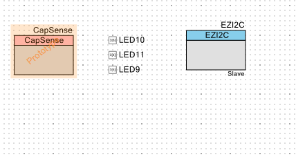
First you need to add the tuner to your project.  In order to do this, start with the last design, then add an EzI2C component.  Here is the new schematic:

Tuner-Schematic

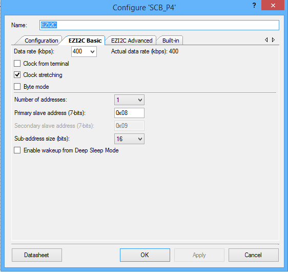
Then you configure the EZ2IC to have 16 bit sub addresses.

Tuner-EzConfig

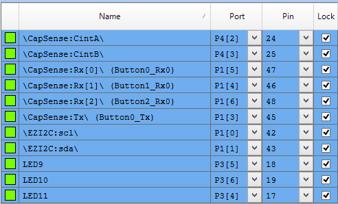
Then assign the EZI2C pins to the KitProg I2C bridge pins

Tuner-DWR

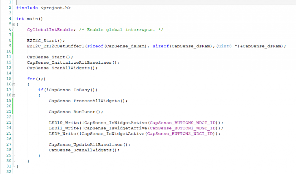
The last step is to write the firmware which is almost exactly what you had in the last project except

  • Lines 8-9 which start the capsense block and setup the Capsense memory buffer to be readable by the remote host
  • Line 21: which updates the Capsense memory buffer with the current state of the capsense parameters

tuner-firmware

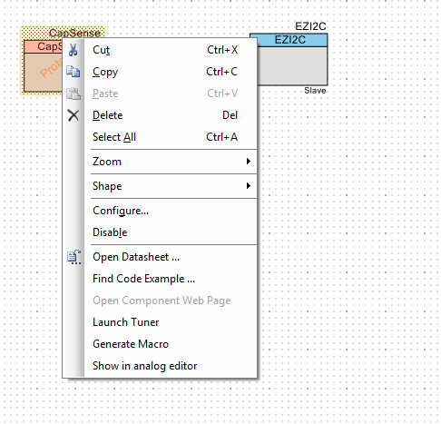
Once all of this is done, build and program the device.  Then start the capsense tuner by right clicking the Capsense component in the schematic and saying “run Tuner”

launch-tuner

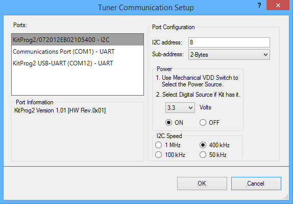
Then configure the tuner communication parameters from the “Tools->Tuner communication setup” menu.  These should match what you have setup in the EZI2C component.  Specifically you need set the I2C addresses to be the same, and you need to have the sub-address set to “2-bytes” which is the same as the 16-bit sub-address which you set in the component above.

tuner-comm-setup

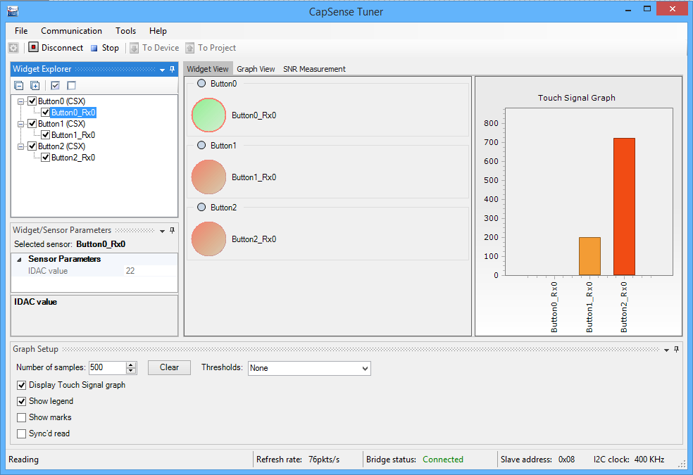
The next step is to press “connect”  and the “start”.  First make sure that your three buttons are working.  In the picture below you can see that I am touching Buttons 1 and 2 as they are “active” (red color) which means that their signal is above the threshold.

2-buttons

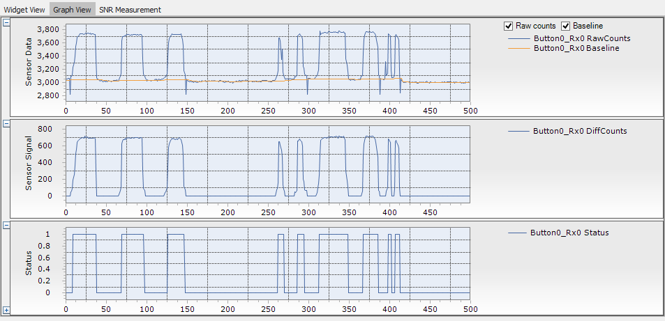
The next step is to look at a “graph view” of button 0.  You can do this by pressing “graph view” and selecting Button0_Rx0.  Once I switch to this view I touch the button 9 times.  You can see that as there are 9 button touches in the Status window.  A status of 1 means that the button is active and a status of 0 is an inactive.

In the sensor data window you can see the “baseline” which is the noise on the sensor node without a touch.  The blue line is the “RawCounts” which the amount of signal on the node.

In the middle window you can see the “Sensor Signal” which is the Sensor Data minus the baseline.  Any time the Sensor Signal is above the touch threshold then the sensor status is active.

Tuner-graph

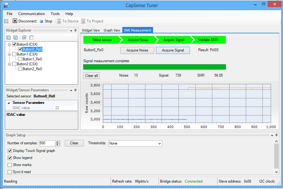
The last step is to use the SNR measurement tab to see how robust your design is.  First click on the “SNR Measurement” tab.  Then pick out which sensor you will measure.  In this case I have setup measurement on “Button_0”.  Then click on “Acquire noise” and wait.  It will make the graph shown below which says that my noise is about 3008-2995 or about 13 counts.

BaselineNoise

The next step is to see how much signal you get.  Start this process by pressing “Acquire Signal” and touching the correct button.  You can see orange line represents the amount of signal when you are touching the sensor.  The system will then calculate the SNR which in this case is 56.85 which is tons.

SNR

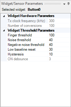
The last thing that you could do is change the Capsense parameters in the sensor parameter screen.  For instance you could change the threshold from 100 to a bigger number to give more reliable touches.

Parameters

OK.  Now I have my capsense buttons working.  In the next posts Ill be ready to talk more about the Smart IO.

You can find this PSoC Creator workspace on github in the directory called “145MutualCap”.  This project is called “TunerMutualCapButtons-145”.
PSoC4000s & CSX Mutual CapSense Buttons Part 1

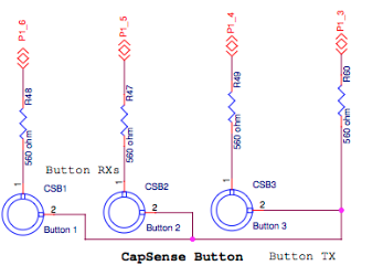
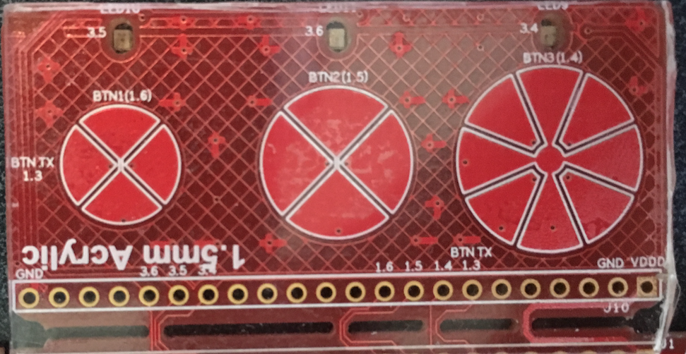
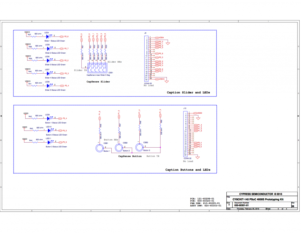
In the previous post I talked about my original goal to learn about the SmartIO.  But, in order fully try out the SmartIO I needed an input source.  On this board I had only one easy input from the factory – specifically the mechanical button on P0[7]- but I wanted to have multiple switches.  Well, the obvious choice was to use the three Capsense Buttons on the user interface expansion board.   When I looked at that board closely I remembered that the buttons were put there to support the new Capsense functionality of the PSoC4000s family.  Inside of Cypress we call the new feature “CSX”, but its real name is “Mutual Capacitance”.  Mutual Capsense works by transmitting a signal on the “Tx” pin and then receiving that signal by capacitively coupling that signal through your finger into the “Rx” line.  Here is a picture of that part of the PCB schematic and a zoom in of the board.  You can see that there are three different size buttons.  Each of the buttons is composed of an even number of pie shaped segments.

mutual-cap-buttonsScreen Shot 2016-03-06 at 2.03.17 PM

The mutual capacitance technique has a much higher Signal-to-Noise Ratio (SnR) as compared to the Self Capacitance technique of previous chips and as a result is more immune to noise and can work through a thicker overlay.  I thought that I would try putting on overlay on my board, so I cut out a piece of 1.5mm acrylic and used double sided tape to attach it to my board.  You can see it in the photograph above.

To make this work I started by creating a new project called “MutualCapButtons”.  I then added the Capsense component and three digital output pins (one for each of the three LEDs on the expansion board).  Here is the schematic:

mutual-button-schematic

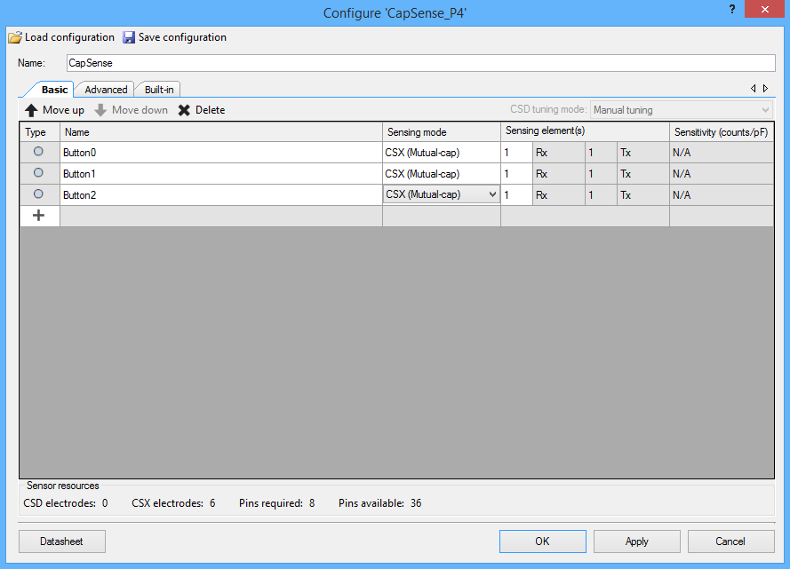
The next step was to configure the CapSense block by double clicking it.  I then added three buttons and set the sensing mode to CSX (Mutual-cap).

mtutual-cap-config

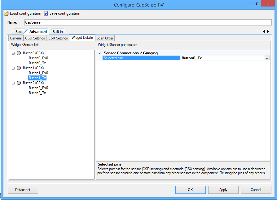
It is possible to have dedicated Tx/Rx pins or you can share the Txs.  To do this, select “Advanced” and “Widget details”.  Then select “Button1_Tx”  and choose its sensor to be the same as “Button0_Tx”.  On this design I shared the Tx between all three of the buttons.

Mutual-sharing

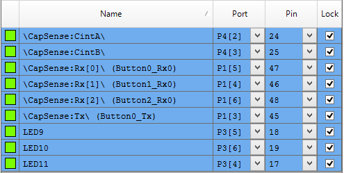
The next step is to assign the pins to the correct Port/Pin locations on the chip:

button-pin-assignments

The last step is to write the firmware

  • Lines 8-10 Start the capsense block and get the scanning going
  • Line 14: If the capsense block is done scanning then process the results
  • Line 16: Take all of the raw data from the scan and setup all of the status information
  • Lines 18-20: If the buttons are being pushed then turn on the corresponding LED
  • Lines 22-23 Start another scan

Mutual-firmware

That is all there is to making it work.

You can find this PSoC Creator workspace on github in the directory called “145MutualCap”.  This project is called “MutualCapButtons-145”.

In the next post Ill talk in detail about using the Capsense Tuner to understand the Capsense performance.

PSoC4000s and the CY8CKIT145 Stamp Board – Part 2

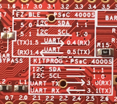
In the previous post, I unboxed the CY8CKIT145 and showed you the schematics.   In this post, I will show you how to build the CapSense firmware that runs on the PSoC4000S.  The first decision I needed to make was how to connect the PSoC and the PRoC chips.  So I looked at the back of the kit and there was a handy-dandy picture of the schematic in the silkscreen.  Here is a zoomed in view:

zoom-145

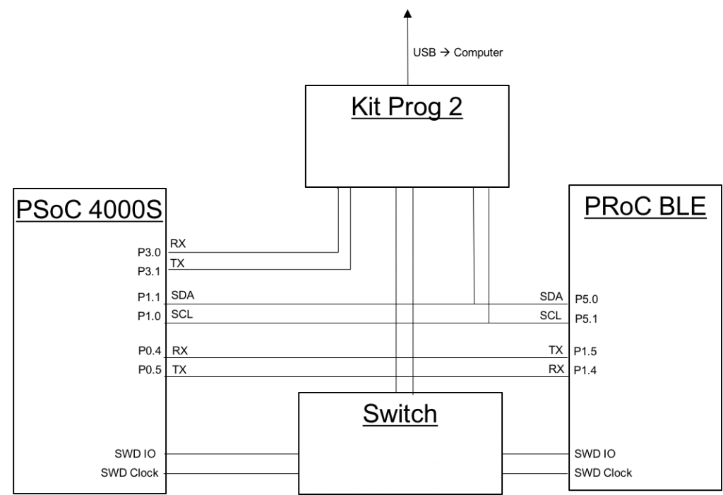
I didn’t have the schematic on the airplane, but here is a more “schematic” view of the chips on the board.

systemschematic-c


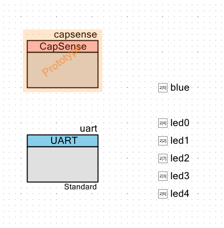
I knew that the UART source code would be slightly easier, so I picked that as the mechanism to connect the chips.  On my computer I had the “capsenseled” workspace from the videos.  So, I created a new PSoC4000S project in that workspace called “145capsenseled.”  I started with the schematic:

  1. Add the new CapSense component.  I am currently running a “nightly build” of PSoC Creator 3.3 that supports the new chip.  You can see in the PSoC Creator release I’m using there is a prototype version of the CapSense component.
  2. Add 5 Digital Output Pins under software control to drive the LEDs that are next to the slider
  3. Add 1 Digital Output pin to drive the blue LED
  4. Add a Serial Communication Block (SCB) configured as a UART

capsenseled-schematic

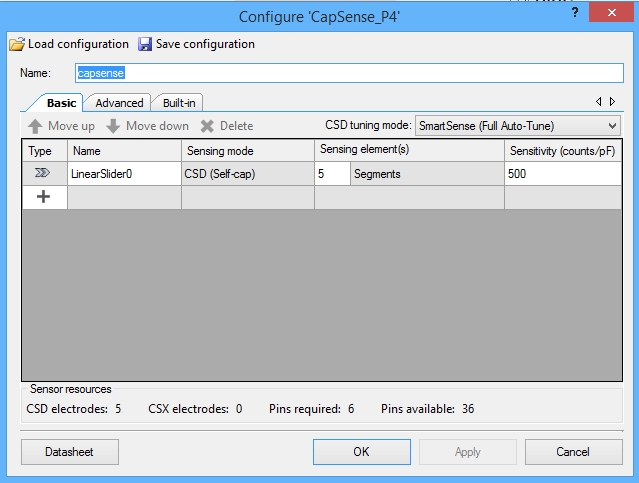
Here is a screenshot of the new CapSense component configuration wizard.  You can see I added a linear slider and set up the component to use SmartSense full-auto tuning.

capsense-configuration

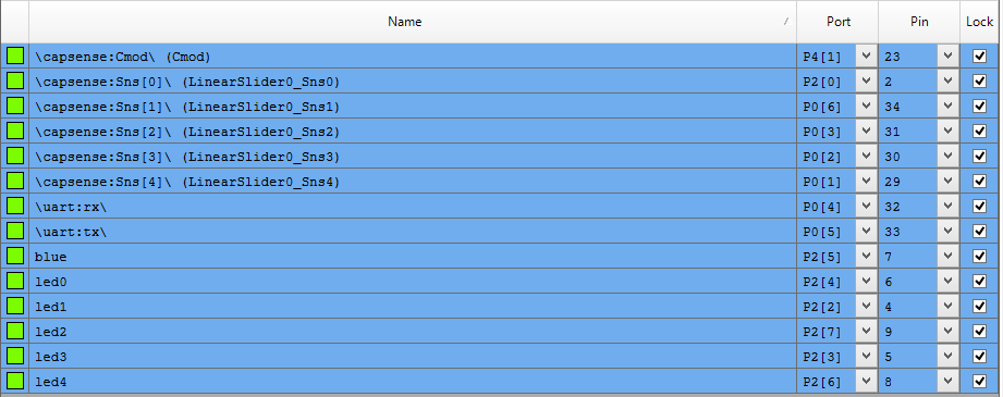
After configuring the CapSense, I set up the pin assignments using the DWR:

capsenseled-pinassignment

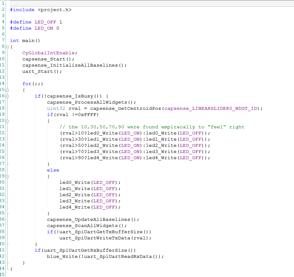
Then I wrote the firmware, which was pretty straight forward.

  • 10-11 start the CapSense
  • 12 start the UART
  • 16: If the CapSense block is done scanning and is idle, then read the CapSense and do something with it (lines 17 -> 41).
  • 18: figure out where the person is touching
  • 19: if they have actually touched the block
  • 22-26 light up the LEDs
  • 30-35 If there is no touch, then turn off the LEDs.
  • 36-37 start the next scan
  • 38-39: If the UART is not busy… then send the position (0-100) or (0xFF if there is no touch).
  • 41-42: If there is a byte in the UART receive buffer, then light up or turn off the Blue LED. (Notice that the LED is active low so I use the “!” operation to flip the state of the signal.

capsense-firmware

After that, I programmed the kit and tested it.  It seemed like everything was good.  In the next post, I’ll show you the schematic and firmware that runs on the PRoC BLE.

You can find the PSoC Creator workspace on github in the directory called “capsenseble-145.”

PSoC4000s and the CY8CKIT145 Stamp Board – Part 1

One of the cool things about my job is I get to try out lots of new development kits before they are released to the general public.  In the previous post I talked about the demonstration I gave at the Embedded World conference using the CY8CKIT-042 BLE.  You can find a complete video tutorial for that project on the cypress.com video tutorial website.  While I was at the conference, I picked up an engineering sample of a new development kit and put it into my backpack because I wanted to try a new feature of PSoC Creator on the way home.  But, when I got on the airplane, I thought I would build the same project I had demonstrated at the conference using this kit.  So, in the next few posts, I am going to show you the new CY8CKIT145 Stamp Board and how to build an IOT solution with it.

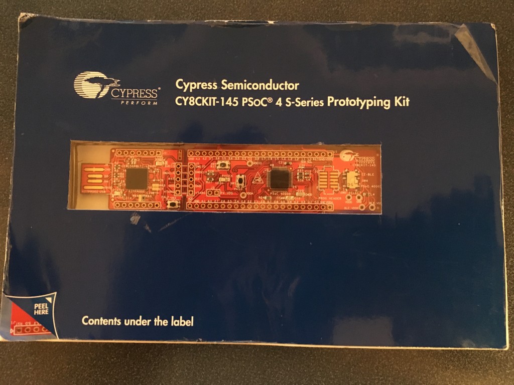
It is called a “stamp board” because it comes in a flat postage stamp-like postcard mailer.  Here is a picture of the front and the back (you can see that it has already lived a hard life riding around in my backpack).

IMG_2720

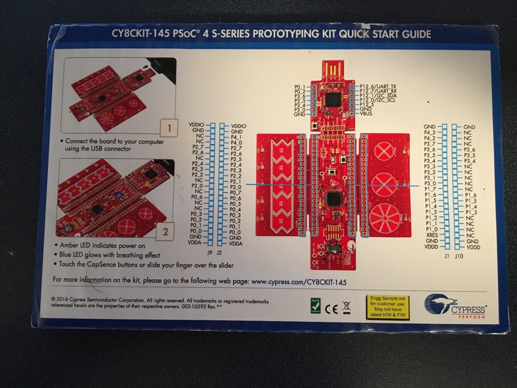
Here is the back of the mailer:

IMG_2722

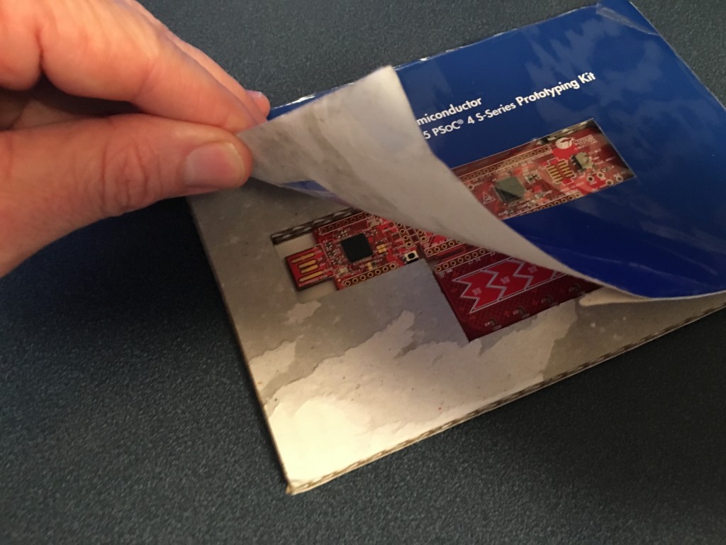
In the picture you can see the yellow label proclaiming this to be an engineering sample.  It doesn’t seem like much, but when you pull back the front of the package you get to see the surprise:

IMG_2721-1

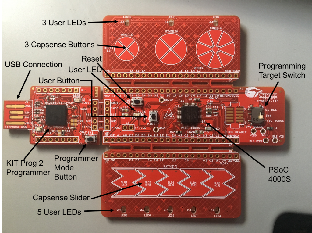
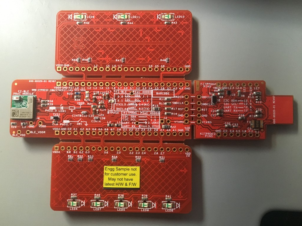
The kit can literally be broken into four separate pieces:

  1. The main board:
    • The PSoC4000S
    • A reset switch
    • A user LED
    • A user push button
    • A programming selector (to pick either the PSoC4000s or the PRoC BLE (that is on the back of the kit)) as the target of the programmer
    • All of the PSoC4000S pins are available on the 100mil center headers
    • A PCB footprint for a 10-pin ARM programming header
  2. A programmer board:
    • A PSoC5LP programmed with KitProg2 Firmware
    • A programmer mode button
    • 100mil center header with some of the PSoC5LP pins
  3. A Capsense slider user interface board with a 5 Segment Slider and 5 LEDs
  4. A Capsense button user interface board with 3 mutual capacitance buttons and 3 LEDs

145front-e

And the back, with the tiny 10mm X 10mm PRoC BLE module:

IMG_2706

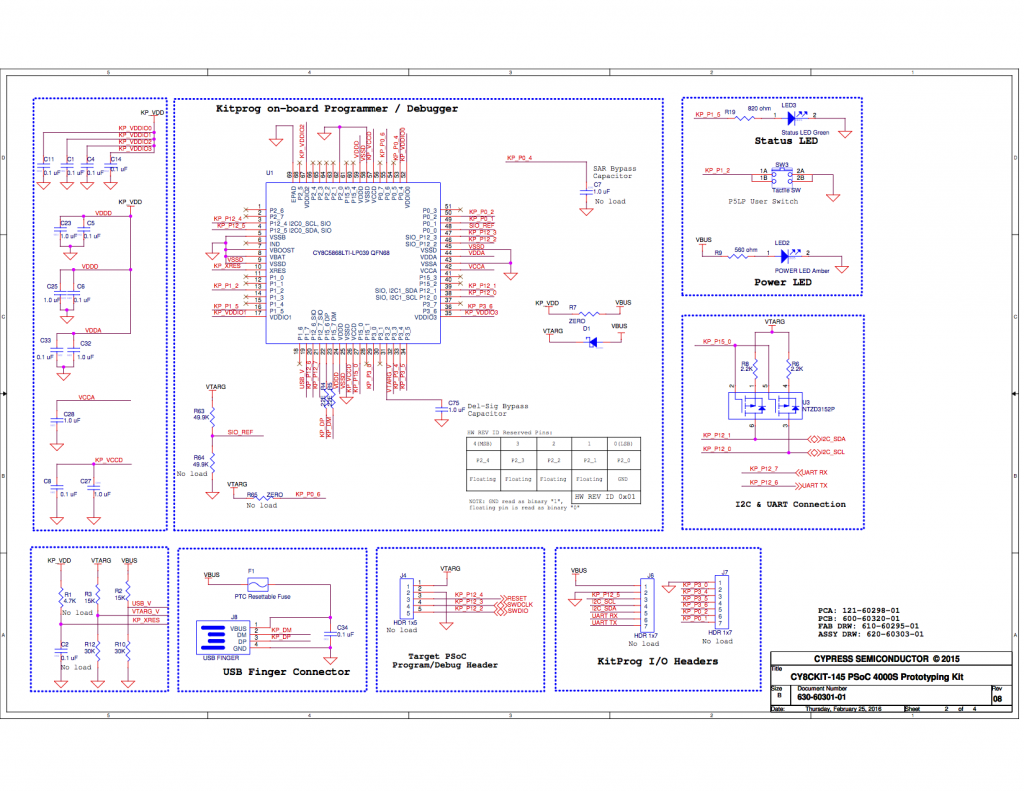
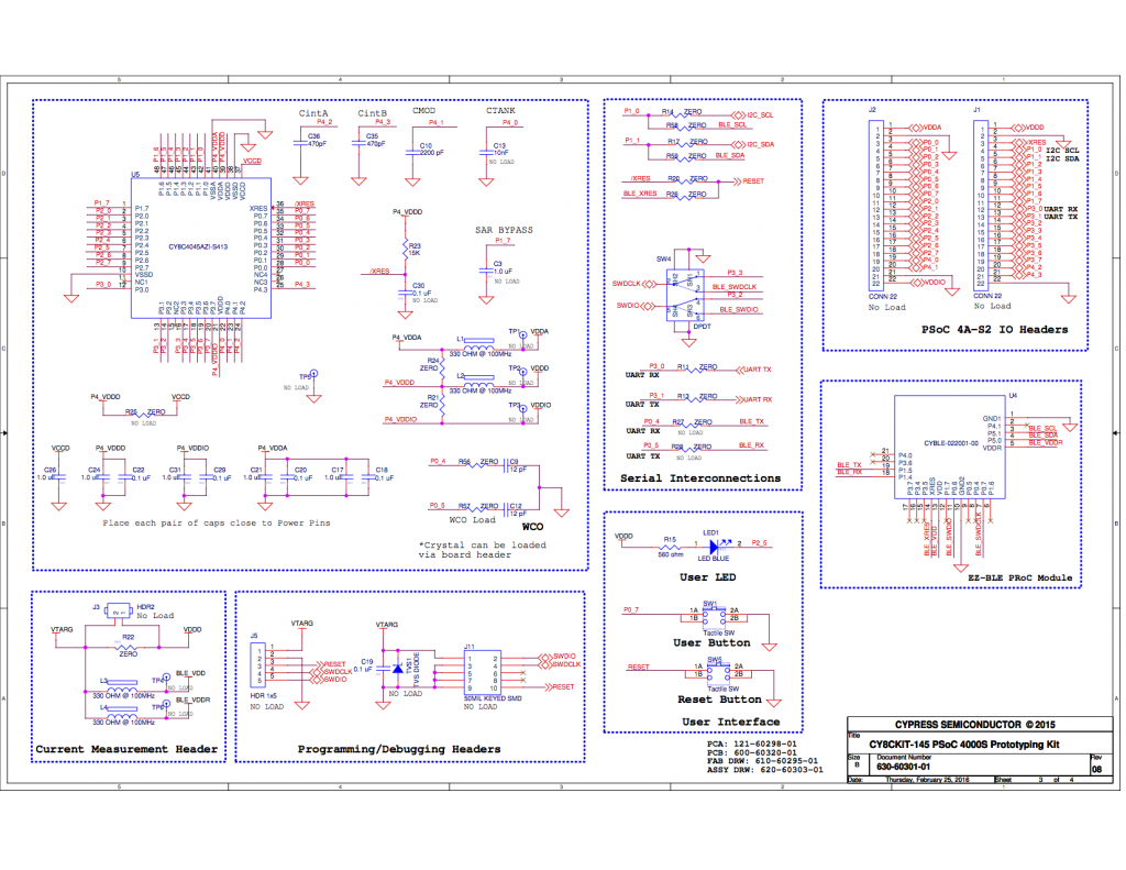
Here is the schematic for the board:

CY8CKIT-145_PSOC_4A-S1-page1

CY8CKIT-145_PSOC_4A-S1 page 2

CY8CKIT-145_PSOC_4A-S1-page3

I wanted to build a project that would have two-way communication between my iPhone and the board, and would be compatible with the Swift App I had written.  The user of the board would have a capsense slider (and LEDs) of which the iPhone App could read the position.  In addition, it would have an LED that the iOS app could turn on and off.  Here is a demonstration that I filmed with my iPhone on the airplane:

In the next post I will describe the overall system and show you the firmware.