In the previous post I took you through the steps in creating the symbol and schematic for the Switch Matrix Component. Next, we need to look at the firmware API. First we will build the public interface to the component. Ill start by adding “SwitchMatrix.h” to my component by
- clicking on the components tab
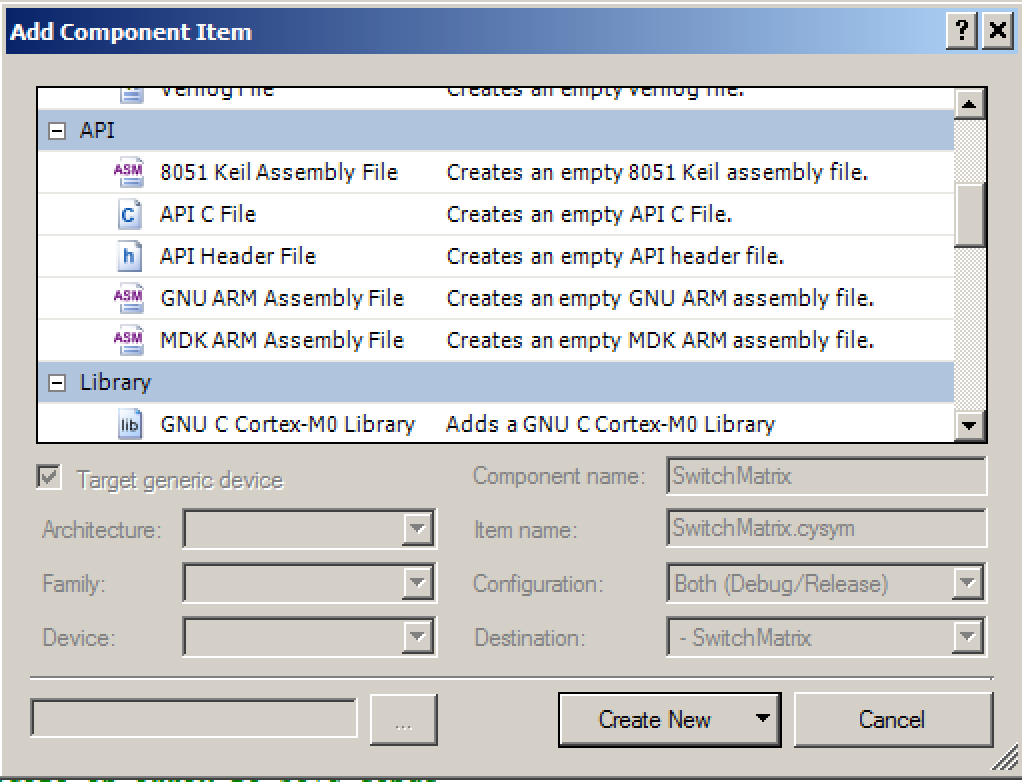
- right clicking on the “SwitchMatrix” component and selecting “Add Component Item…”
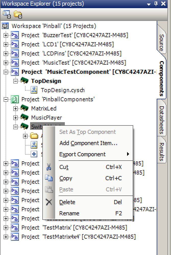
- Choosing “API–>API Header File”
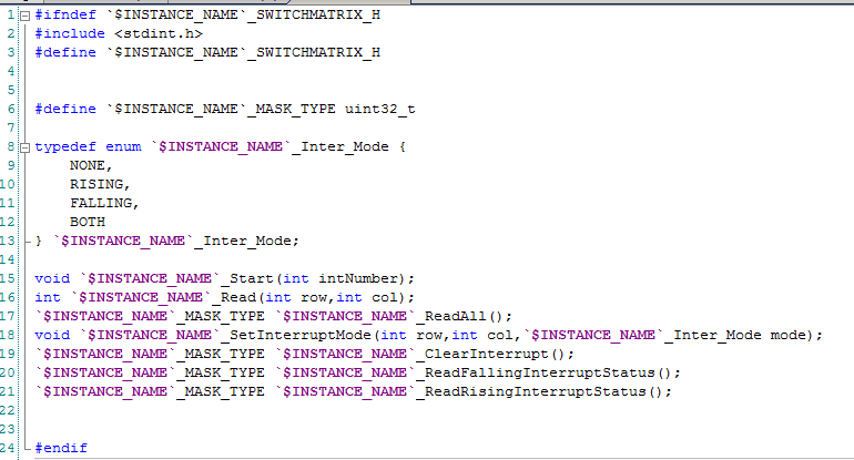
In the SwitchMatrix.h I define the public interface to the component. For the switches you want to have:
- A polling interface
- An interrupt based interface
On line 6 I wanted a bit mask to represent the status of the switches. When I setup things originally I was not sure how many bits I was going to support and I wanted to be able to change the length of the bit mask with just one #define. Given that my switch matrix component can do 8 rows and 8 columns a.k.a. 64 switches I probably should have set this mask to uint64_t. BUT when I started the work I didnt know that type existed so I just used uint32_t. It is even a bit more confusing because Cypress provides the non CMSIS-CORE definition of uint8, uint16, uint32… All that aside, if you change the #define it will change for all of the switches.
On lines 8-13 I define a new type that defines the list of possible interrupts (No interrupt, rising edge, falling edge or both edges).
Line 15 defines the start interface. This component uses the systick timer to run the state machine that sequences turning on/off of the switch rows/columns. The “number” is which of the 4 Cypress SysTick interrupt vectors to use.
Line 16 returns the status of switch at row,column and returns 1 for active and 0 for inactive.
Line 17 returns the status of ALL of the switches into a bit mask
Line 18-21 defines the interrupt based interface to the switch matrix.
- Line 18 request to be interrupted based on row,column
- Line 19: clears the interrupt flags
- Line 20: returns the falling interrupt flags
- Line 21: returns the rising interrupt flag
The big question with the interrupt interface is: What function is called when an interrupt happens? The answer is: I used the “cyapicallbacks.h” functionality that PSoC Creator provides for you (more to follow).
All of the bit masks that I used are of the form of [ r2c2,r1c2,r0c2 r2c1,r1c1,r0c1 r2c0,r1c0,r0c0 ]
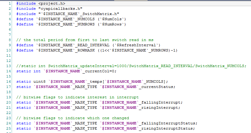
The next thing that you need to do is to implement the actual firmware for the system. Start by adding “SwitchMatrix.c” to the component (using the same method detailed above except choose “API C File”.
On lines 4-9 I turn Symbol Parameters into #defines which can be used in my source code. Remember that we let the user define the $NumCols, $NumRows and $RefreshInterval.
Line 10 is a neat way to make a bit mask of all 1’s up to a bit position. e.g if you want 3’s aka 0b111 then you can do 2^3-1 = 7 = 0b111. This bit mask is used to mask off the read bits from the pins.
Line 14 defines a variable which is the Current Column that you are looking at. This changes every READ_INTERVAL/# of column ms and cycles through the columns.
Line 16 is an array of the bit masks of the status of each of the columns.
Line 17 holds flags for which rising and falling switches you are interested in for an interrupt.
Line 24-25 holds the status of which of the switches caused the interrupt.
The SetInterruptMode function sets the bit mask for the rising or falling interrupt. The $INSTANCE_NAME_MASK_TYPE is the type (in this case uint32_t) of the bit mask for switches. On line 41-42 I turn off the interrupt. Then the switch on line 44 resets the bit based on the input.
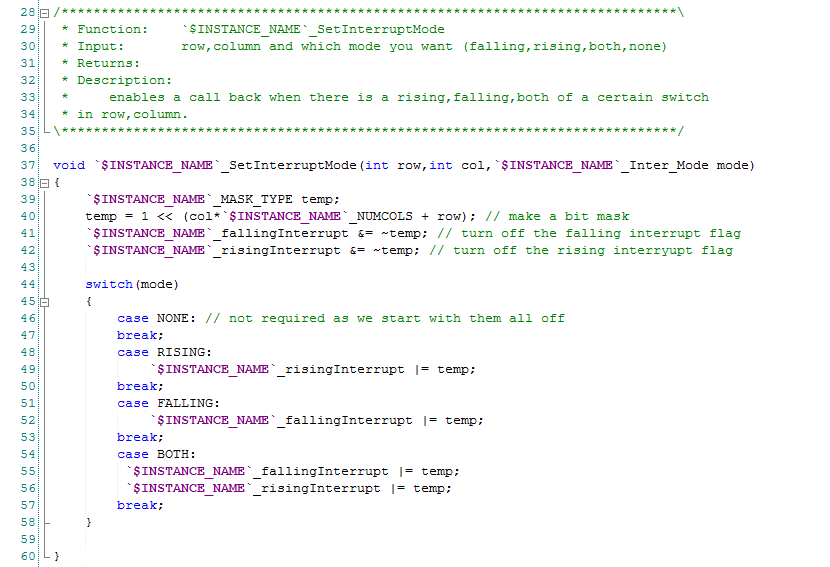
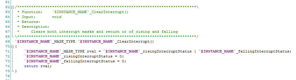
The ClearInterrupt function just clears all of the interrupt flags (rising and falling). It returns the state of the flags (before the reset).
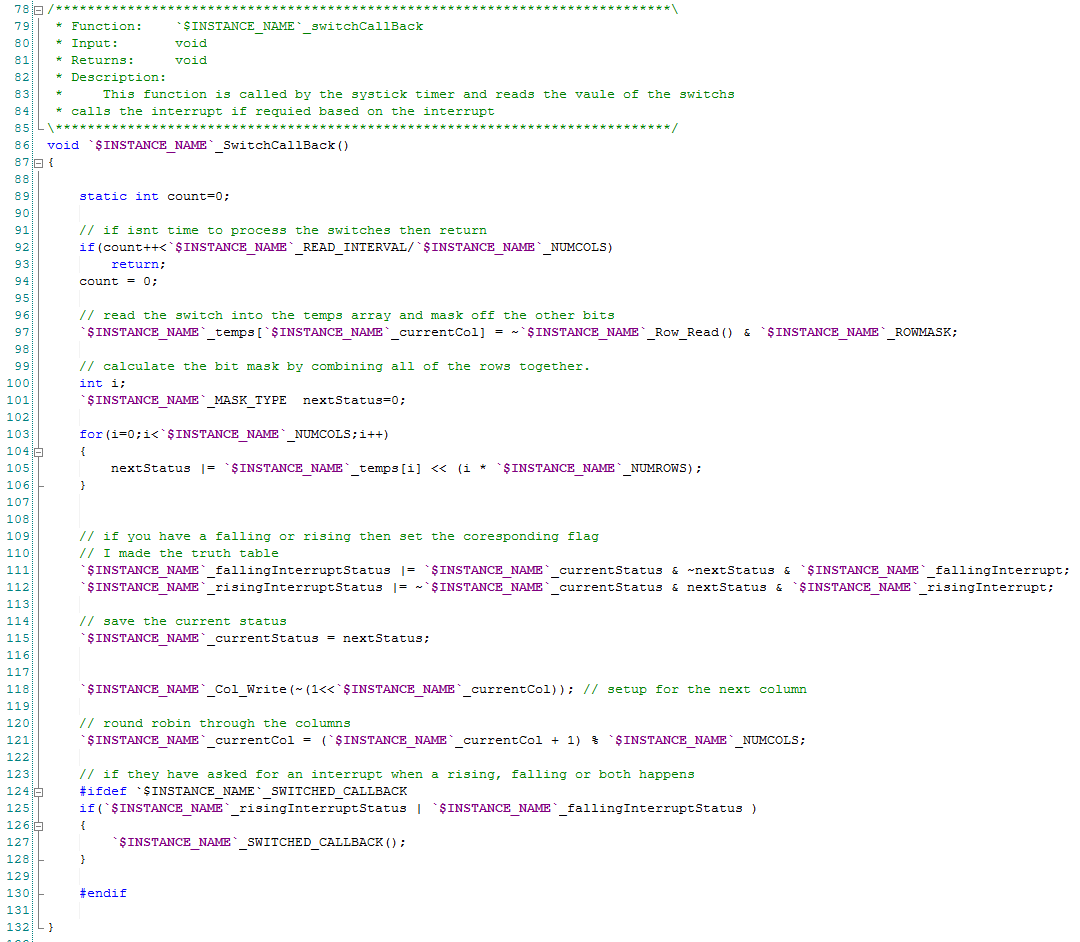
The function “SwitchCallBack” (which should have been defined static) is the main brains of switch sequencer. It is called every 1 ms by the SysTick callback. Lines 92-94 lowers the frequency of doing something by only updating the status etc every “READ_INTERVAL/Column” ms.
Line 97 reads the digital input pins of the switch matrix. It uses the row_mask to mask off the bits that are not being used. It turns out that this was not needed because when you read a bus of pins the Cypress APIs automatically mask off the other bits.
Lines 100-105 builds a bit mask of the status of all of the bits.
Line 111-112: sets the interrupt flags by comparing the “nextStatus” with the “currentStatus”
Line 118 moves turns on the next column pins.
Line 124: Calls back if there is an interrupt. It uses the “cyapicallbacks.h” to figure out what to call back. This could have been done by registering a function pointer… but oh well that is what Cypress decided. To use this you do a #define MatrixSwitch_SWITCHED_CALLBACK with the name of the function you want called.
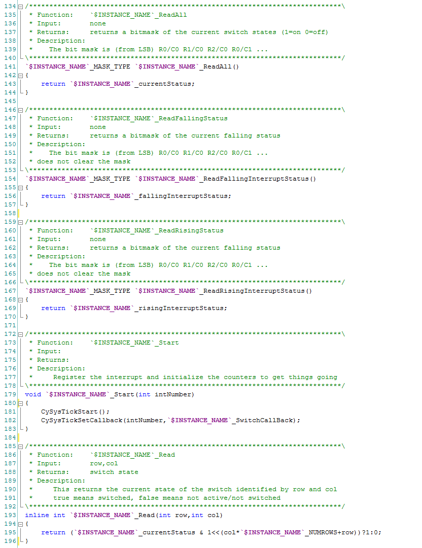
The next functions are just simple helper functions which return a status or start the component.
In the next post I will show you some simple firmware to test the component.
You can find all of the source code and files at the IOTEXPERT site on github.
Index
Description
Pinball: Newton's Attic Pinball
An introduction to the project and the goals
Pinball: Lotsa Blinking LEDs
Everyone needs a bunch of LEDs on their Pinball Machine
Pinball: Matrix LEDs (Part 1)
Saving PSoC pins by using a matrix scheme
Pinball: Matrix LEDs (Part 2)
Solving some problems with the matrix
Pinball: Matrix LEDs Component
How to turn the Matrix LED into a component
Pinball: A Switch Matrix
Implementing a bunch of switches
Pinball: Switch Matrix Component (Part 1)
The switch matrix component implementation
Pinball: Switch Matrix Component (Part 2)
The firmware for matrix component
Pinball: Switch Matrix Component (Part 3)
Test firmware for the matrix component
Pinball: The Music Player (Part 1)
The schematic and symbol for a Music Player component
Pinball: The Music Player (Part 2)
The Public API for the Music Player component
Pinball: The Music Player (Part 3)
The firmware to make the sweet sweet music
Pinball: The Music Player (Part 4)
The test program for the music player
Pinball: The Motors + HBridge
Using an Bridge to control DC Motors
Pinball: The Eagle Schematic
All of the circuits into an Eagle schematic
Pinball: The Printed Circuit Board 1.0
The first Eagle PCB layout of the printed circuit board
Pinball: The PCB Version 1.0 Fail
Problems with the first version of the Eagle PCB layout
Pinball: PCB Layout 1.2 Updates using Eagle
Fixing the errors on the first two versions of the Eagle PCB
Pinball: Assemble and Reflow the 1.2 PCB
Assembling the Eagle PCB
Pinball: Testing the Eagle PCB
Firmware to test the newly built Pinball printed circuit board
Pinball: Debugging the Motor Driver
Fixing the motor driver PSoC project
Pinball: Hot-Air Reworking the Accelerometer Solder
Using a Hot-Air Rework tool to reflow a QFN
Pinball: Debugging the LM317 Power Supply- A Tale of Getting Lucky
Debugging the LM317/LM117 power supply
No comment yet, add your voice below!