When Billy and I talked about making the electronics package for the Pinball machine, I suggested that it would be cool to have some motors. Mr. Mechanical Engineer’s eyes lit up when I made that suggestion. There are tons of things that the kids to could with a couple of controllable motors. You could imagine conveyor belts, spinning obstacles, and all manner of lift systems.
I wanted to use inexpensive DC Toy motors. The problem with most motors is that they require higher voltages (5-9 volts) and currents (250mA for the one that I wanted) than the PSoC (or generally any MCU) is capable of delivering. Well that’s OK, it turns out there is a whole class of Power Management ICs (PMICs) which provide translation between an MCU and a Motor. The one that I am going to use is called the TB6612. This chip has dual Hbridges that help you control both the speed and direction of two motors.
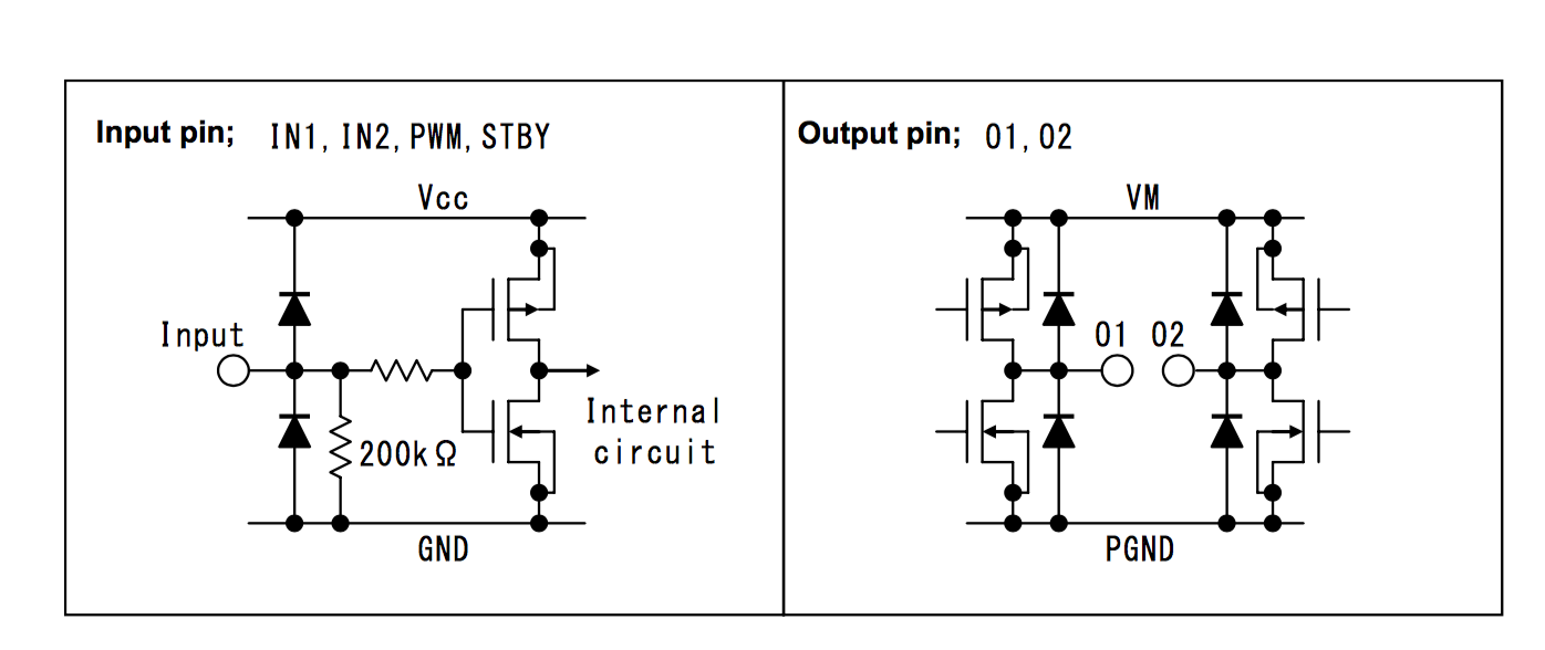
First, the chip uses NMOS transistors configured as switches to let you control higher power (voltage and current) circuits. Here is a picture of the input to the PMIC from the datasheet:
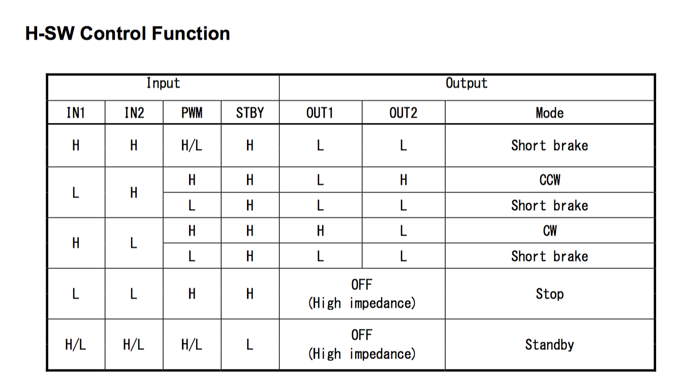
Second you want to be able to control the speed and direction of the motor. Here is a screen shot from the data sheet that shows the inputs and what happens with the motor.
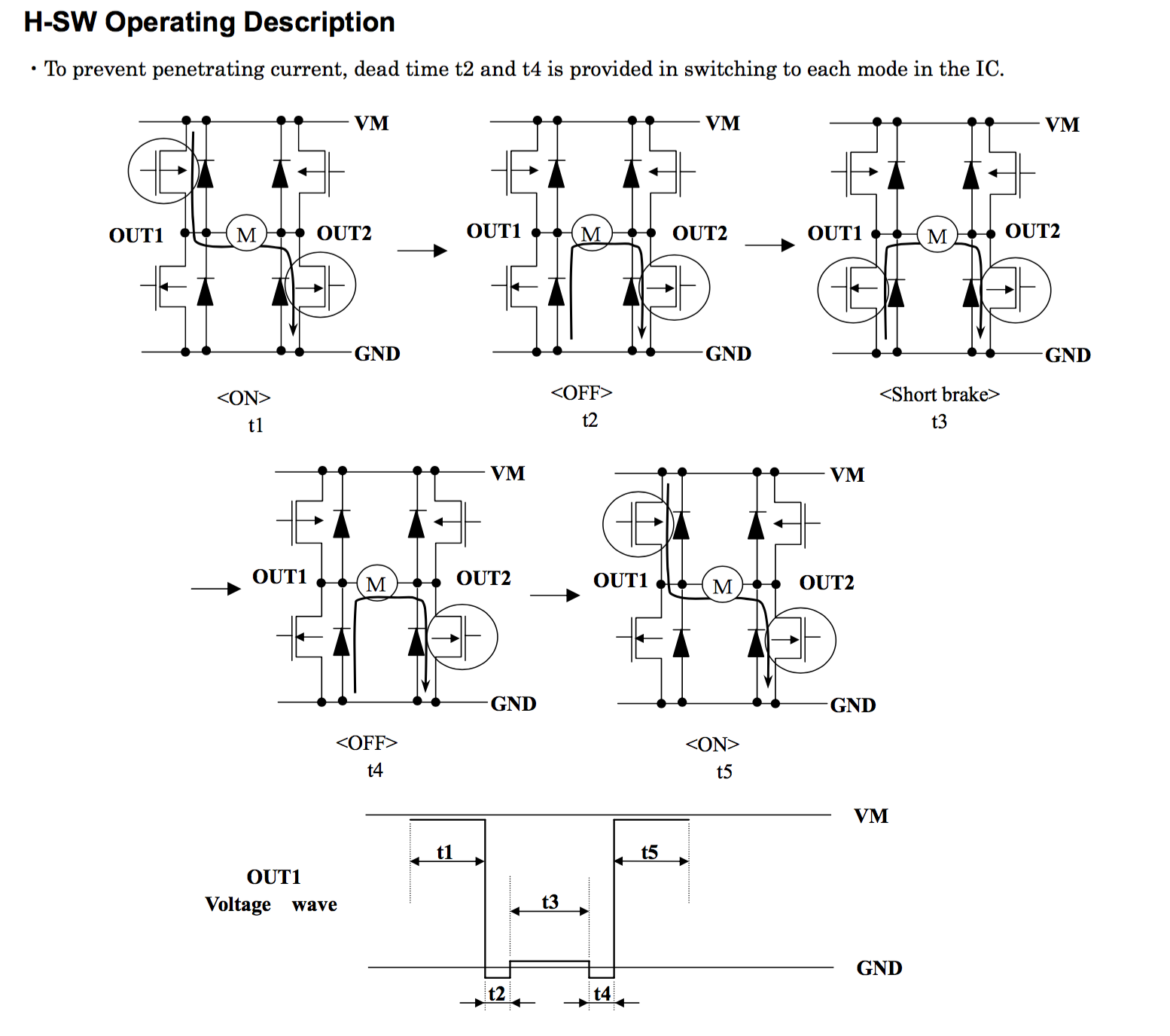
Here is a picture that shows you how the current flows through the Hbridge as well as showing the circuit that keeps you from short circuiting between the phases.
So, how do you control the speed? Simple, you use a PWM to create a train of pulses that have different duty cycles. The greater the duty cycle, the faster the motor goes. The lower the duty cycle, the slower the motor goes.
One last problem. The chip requires IN1, IN2, PWM and Standby, but I want to only use two outputs from the PSoC. So, what I decide to do is
- Turn the standby off (so that the chip is always active)
- Attach the PWM input to high so that the motor is always spinning
- Attach In1 and In2 to the PSoC. The PSoC will then set them to the correct value and PWM.
In the next post Ill start the process of turning all of the different blocks into a schematic that can then be turned into a printed circuit board.
You can find all of the source code and files at the IOTEXPERT site on github.
Index
Description
Pinball: Newton's Attic Pinball
An introduction to the project and the goals
Pinball: Lotsa Blinking LEDs
Everyone needs a bunch of LEDs on their Pinball Machine
Pinball: Matrix LEDs (Part 1)
Saving PSoC pins by using a matrix scheme
Pinball: Matrix LEDs (Part 2)
Solving some problems with the matrix
Pinball: Matrix LEDs Component
How to turn the Matrix LED into a component
Pinball: A Switch Matrix
Implementing a bunch of switches
Pinball: Switch Matrix Component (Part 1)
The switch matrix component implementation
Pinball: Switch Matrix Component (Part 2)
The firmware for matrix component
Pinball: Switch Matrix Component (Part 3)
Test firmware for the matrix component
Pinball: The Music Player (Part 1)
The schematic and symbol for a Music Player component
Pinball: The Music Player (Part 2)
The Public API for the Music Player component
Pinball: The Music Player (Part 3)
The firmware to make the sweet sweet music
Pinball: The Music Player (Part 4)
The test program for the music player
Pinball: The Motors + HBridge
Using an Bridge to control DC Motors
Pinball: The Eagle Schematic
All of the circuits into an Eagle schematic
Pinball: The Printed Circuit Board 1.0
The first Eagle PCB layout of the printed circuit board
Pinball: The PCB Version 1.0 Fail
Problems with the first version of the Eagle PCB layout
Pinball: PCB Layout 1.2 Updates using Eagle
Fixing the errors on the first two versions of the Eagle PCB
Pinball: Assemble and Reflow the 1.2 PCB
Assembling the Eagle PCB
Pinball: Testing the Eagle PCB
Firmware to test the newly built Pinball printed circuit board
Pinball: Debugging the Motor Driver
Fixing the motor driver PSoC project
Pinball: Hot-Air Reworking the Accelerometer Solder
Using a Hot-Air Rework tool to reflow a QFN
Pinball: Debugging the LM317 Power Supply- A Tale of Getting Lucky
Debugging the LM317/LM117 power supply
No comment yet, add your voice below!