In the last several posts I talked in detail about reducing the number of pins required to drive a bunch of LEDs by putting them into a matrix. In this post I am going to talk about doing exactly the same thing for switches. For the pinball machine I would like to have at least 9 switches, so I will arrange them into a 3×3 matrix which will require only 6 pins.
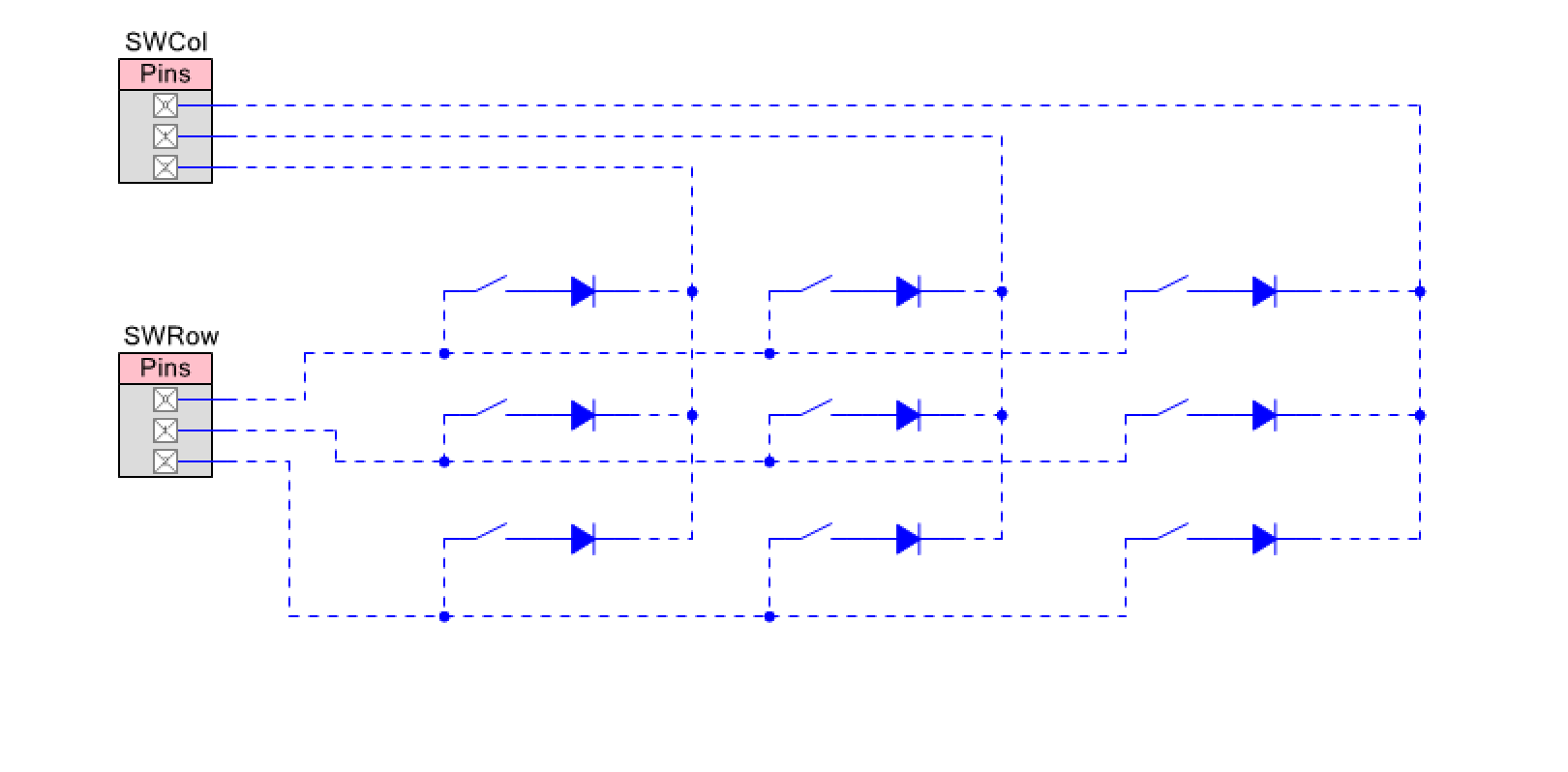
With a few minor differences, the system works the same as the LED matrix. First you enable the pull-up resistors on the SWRow pins. This forces a weak 5v onto the row pins. Then you enable one column at a time by writing a “0” which forces 0v onto that column pin. You also write a 1 onto the other column pins which forces 5V onto those pins. You can see in the picture below that if you press the switch labeled S0,0 you will end up with 0V on the top input to the SWRow pin which will be read as 0. With nothing else pressed you will end up with 1s being read on the other two row pins (because of the pullup resistors).

So what are the diodes for? If you don’t have the diodes then you have what is called the ghosting problem. Ghosting means that when you press two switches at the same it will appear as a third different switch-meaning you will have a “ghost” press. In the example diagram below I do exactly the same thing as before, except I also press Switch 0,1 and Switch 1,1. Without the diodes this has the effect of propagating a 0 onto the input of Row 1 which makes it appear as if S1,0 is active even though it is not.
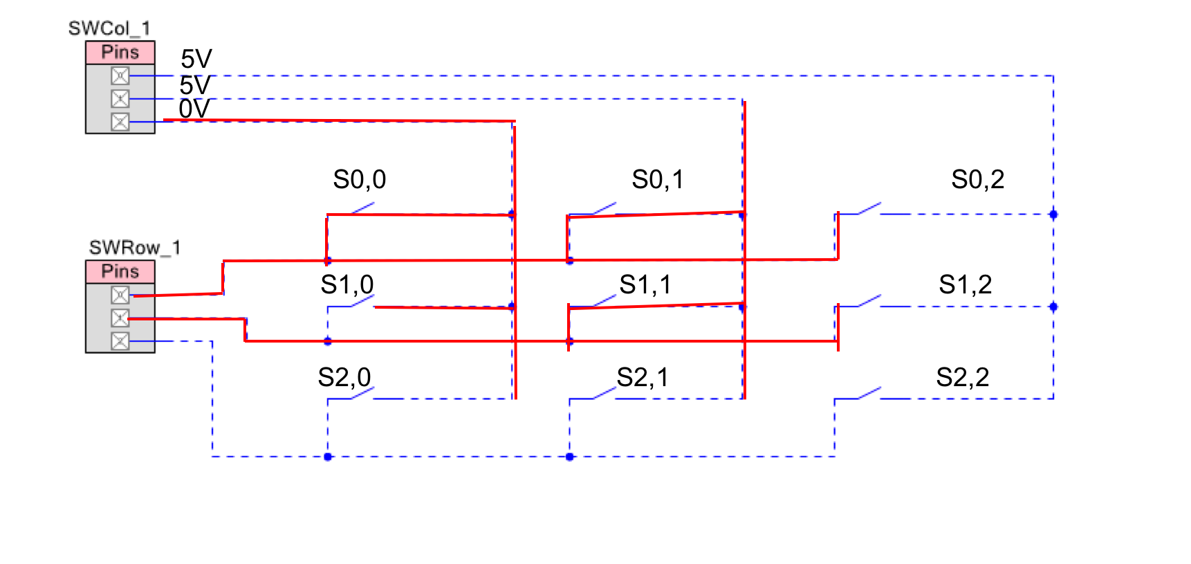
Here is the same picture with the diodes in. You can see that the diode next to S0,1 and S1,1 are reversed biased and don’t conduct the 0.

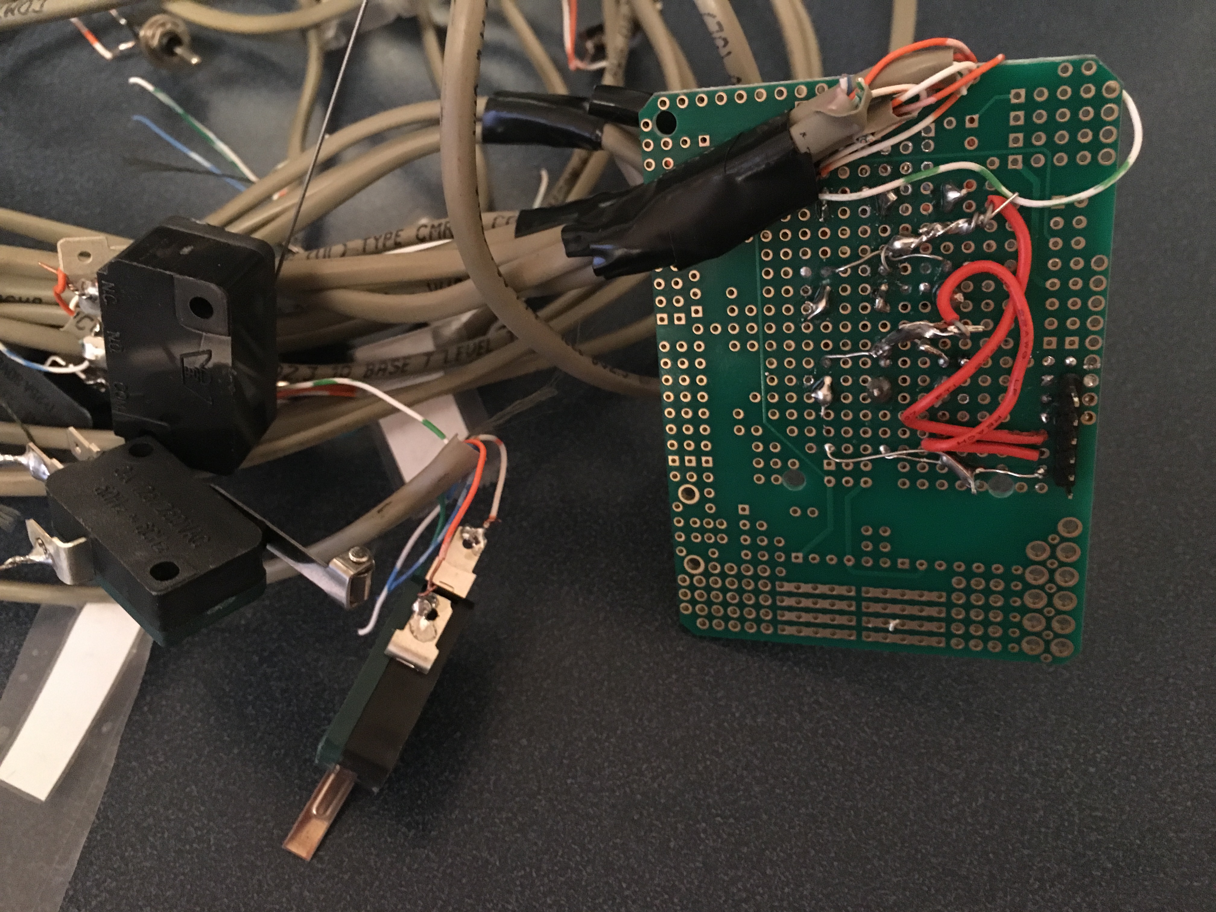
To make the system I once again enlist my Lab Technician Nicholas and his friend Anna.

And after some time and help and not too many burns:
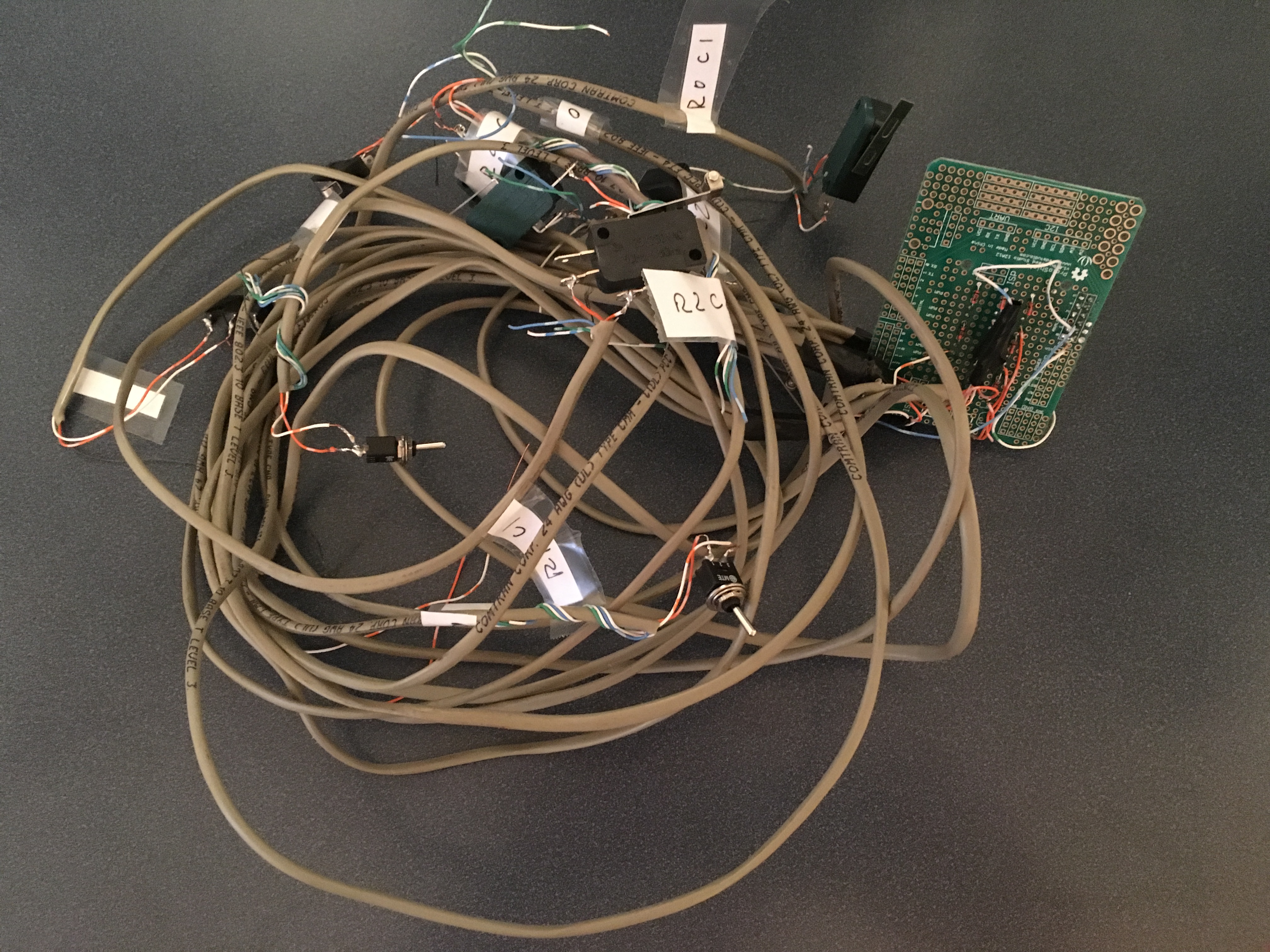
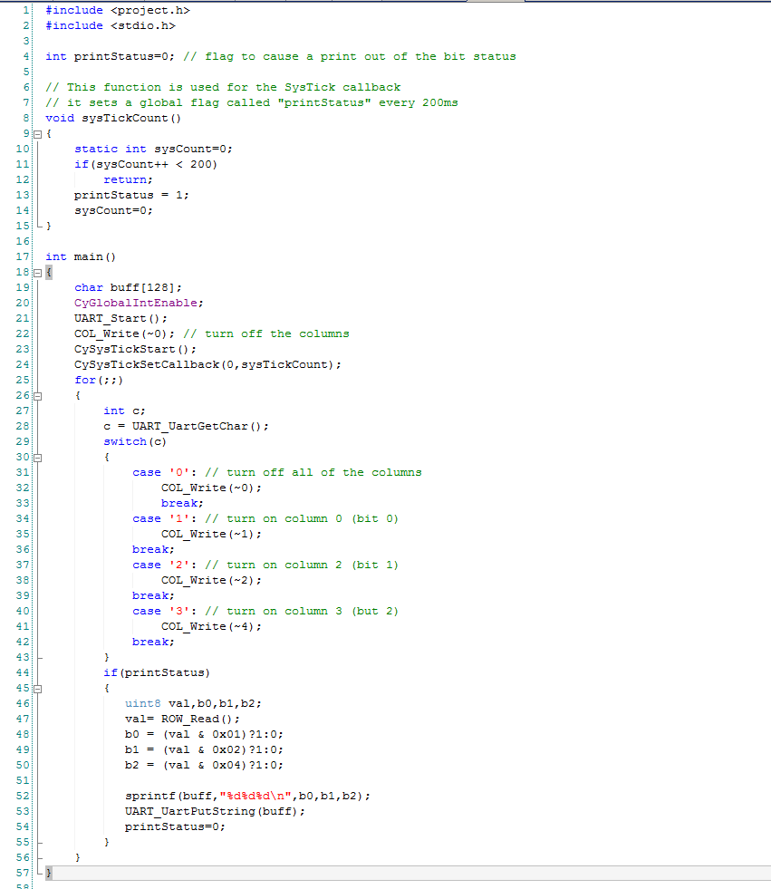
Once I have the switch matrix test board setup, Ill build a project to test it. The project is called “SwitchTestWiring”. The firmware uses the systick timer to trigger a printout of the data every 200ms. I then use the UART to read 0,1,2,3 to turn on the corresponding column. Notice that I built a 3×3 test.
In the next posts Ill build a component to run the matrix:
You can find all of the source code and files at the IOTEXPERT site on github.
Index
Description
Pinball: Newton's Attic Pinball
An introduction to the project and the goals
Pinball: Lotsa Blinking LEDs
Everyone needs a bunch of LEDs on their Pinball Machine
Pinball: Matrix LEDs (Part 1)
Saving PSoC pins by using a matrix scheme
Pinball: Matrix LEDs (Part 2)
Solving some problems with the matrix
Pinball: Matrix LEDs Component
How to turn the Matrix LED into a component
Pinball: A Switch Matrix
Implementing a bunch of switches
Pinball: Switch Matrix Component (Part 1)
The switch matrix component implementation
Pinball: Switch Matrix Component (Part 2)
The firmware for matrix component
Pinball: Switch Matrix Component (Part 3)
Test firmware for the matrix component
Pinball: The Music Player (Part 1)
The schematic and symbol for a Music Player component
Pinball: The Music Player (Part 2)
The Public API for the Music Player component
Pinball: The Music Player (Part 3)
The firmware to make the sweet sweet music
Pinball: The Music Player (Part 4)
The test program for the music player
Pinball: The Motors + HBridge
Using an Bridge to control DC Motors
Pinball: The Eagle Schematic
All of the circuits into an Eagle schematic
Pinball: The Printed Circuit Board 1.0
The first Eagle PCB layout of the printed circuit board
Pinball: The PCB Version 1.0 Fail
Problems with the first version of the Eagle PCB layout
Pinball: PCB Layout 1.2 Updates using Eagle
Fixing the errors on the first two versions of the Eagle PCB
Pinball: Assemble and Reflow the 1.2 PCB
Assembling the Eagle PCB
Pinball: Testing the Eagle PCB
Firmware to test the newly built Pinball printed circuit board
Pinball: Debugging the Motor Driver
Fixing the motor driver PSoC project
Pinball: Hot-Air Reworking the Accelerometer Solder
Using a Hot-Air Rework tool to reflow a QFN
Pinball: Debugging the LM317 Power Supply- A Tale of Getting Lucky
Debugging the LM317/LM117 power supply
No comment yet, add your voice below!