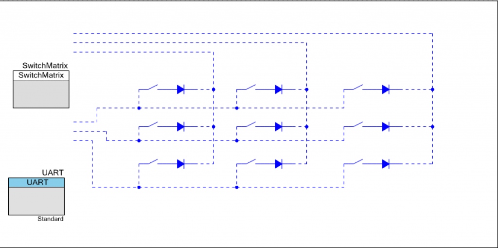
In order to build a test case for the SwitchMatrix component, I first create new project called “SwitchMatrixTest”. Then I create a schematic with the component and a UART. Notice that I draw the “external components” of the switch matrix, but I can’t hook it up to the actual component because I never created the external terminals for the SwitchMatrix component (bad Alan).
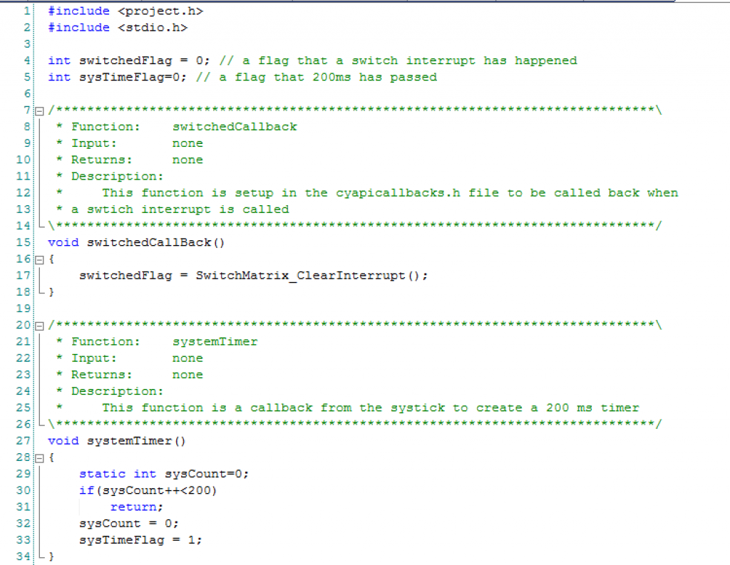
Next I edit the main.c First, lines 4-5 are to flags that are set by interrupt service routines. The switchedFlag is set by the component when you have registered your interested in a switch changing event. The sysTimeFlag is set every 200ms by the sysTick ISR.
Lines 15-19 saves the status of the switch interrupt flags for use by the main loop.
Line 27-34 is a simple timer that I implement using the SysTick timer. I set a flag every 200ms which I use to printout things on a regular basis in the main loop.
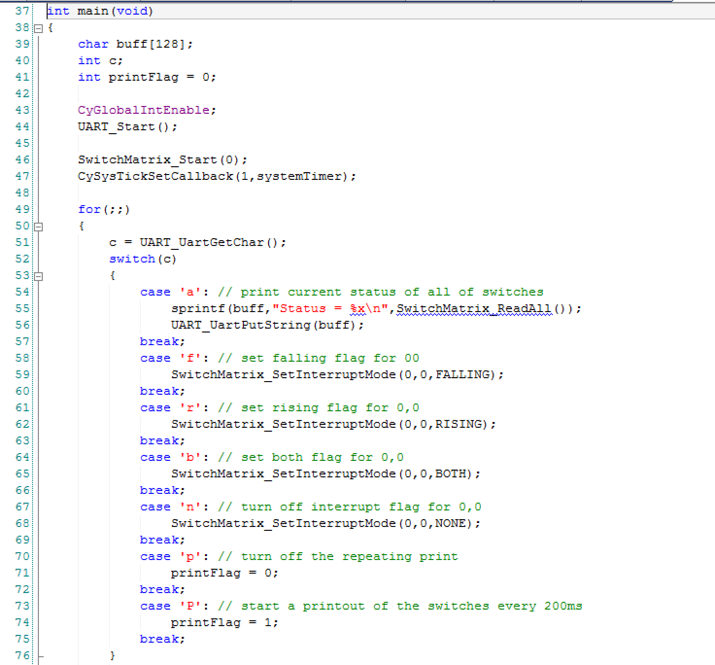
 In the main program I first start all of the components, interrupts etc in lines 43-47. On lines 52-75 I process the user input and try out different functions of the component.
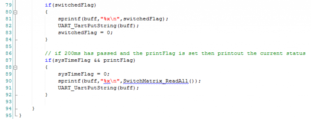
Lines 79-84 causes the status of the switches to be printed out IF the switched flag is set. The switched flag is set in the callback function switchedCallBack();
Lines 87-91 print out the status of the switches every 200ms based on the system timer.
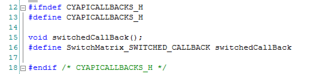
In order to get my SwitchMatrix component to call back when a rising/falling edge occurs, I need to register that call back in the cyapicallbacks.h. I first make a forward declaration of the function on line 15. Then I #define the “SwitchMatrix_SWITCHED_CALLBACK” which tells the component which function to call.
In the next set of posts I will discuss the Music Player.
You can find all of the source code and files at the IOTEXPERT site on github.
Index
Description
Pinball: Newton's Attic Pinball
An introduction to the project and the goals
Pinball: Lotsa Blinking LEDs
Everyone needs a bunch of LEDs on their Pinball Machine
Pinball: Matrix LEDs (Part 1)
Saving PSoC pins by using a matrix scheme
Pinball: Matrix LEDs (Part 2)
Solving some problems with the matrix
Pinball: Matrix LEDs Component
How to turn the Matrix LED into a component
Pinball: A Switch Matrix
Implementing a bunch of switches
Pinball: Switch Matrix Component (Part 1)
The switch matrix component implementation
Pinball: Switch Matrix Component (Part 2)
The firmware for matrix component
Pinball: Switch Matrix Component (Part 3)
Test firmware for the matrix component
Pinball: The Music Player (Part 1)
The schematic and symbol for a Music Player component
Pinball: The Music Player (Part 2)
The Public API for the Music Player component
Pinball: The Music Player (Part 3)
The firmware to make the sweet sweet music
Pinball: The Music Player (Part 4)
The test program for the music player
Pinball: The Motors + HBridge
Using an Bridge to control DC Motors
Pinball: The Eagle Schematic
All of the circuits into an Eagle schematic
Pinball: The Printed Circuit Board 1.0
The first Eagle PCB layout of the printed circuit board
Pinball: The PCB Version 1.0 Fail
Problems with the first version of the Eagle PCB layout
Pinball: PCB Layout 1.2 Updates using Eagle
Fixing the errors on the first two versions of the Eagle PCB
Pinball: Assemble and Reflow the 1.2 PCB
Assembling the Eagle PCB
Pinball: Testing the Eagle PCB
Firmware to test the newly built Pinball printed circuit board
Pinball: Debugging the Motor Driver
Fixing the motor driver PSoC project
Pinball: Hot-Air Reworking the Accelerometer Solder
Using a Hot-Air Rework tool to reflow a QFN
Pinball: Debugging the LM317 Power Supply- A Tale of Getting Lucky
Debugging the LM317/LM117 power supply
No comment yet, add your voice below!