On October 24, I will be teaching a Mouser video training workshop … live streaming on the internet. The workshop will be about PSoC, WICED, WiFi and Bluetooth. I am going to show PSoC Creator, WICED Studio and Cypress’s new development tool Modus Toolbox.
Cypress introduced it’s first mass market microcontroller in 2001. It used a Cypress designed 8 bit CISC processor running at 24 MHz, with as little as 4 KB Flash and 256 bytes RAM. Wrapped around that was a neat array of programmable analog and digital blocks. This may not sound like much, but with a creative mindset you could get these parts to do amazing things. For instance, I once implemented a complete ultrasonic ranging sensor with full wave analog demodulation in a single PSOC1 as shown below.
PSOC1 Ultrasonic Ranging
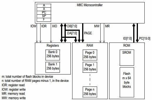
With CPU resources at a premium, you had to write tight, efficient code to get the most out of PSOC1. A single C library could consume the entire Flash. Consequently, I wrote a lot of assembly code. That’s not so bad, since I actually enjoy it more than C. There’s a certain elegance to well written, fully commented machine code. In the case of PSOC1, here’s what you had to work with: 5 registers, some RAM and Flash. That’s it. Real Men Write In Assembly.
M8C Architecture
We’ll start with simple machine code instruction to make the CPU do something. You can reference the M8C assembly language user guide here for more details. To get the M8C to execute 2+3=5 we write:
mov A,2 ;Load A with 2
add A,3 ;Add 3 to A. Result=5 is in A
We can get fancy by using variables. Let’s add R=P+Q. Assume P is at RAM location 0x20 and Q is at location 0x21, and R is at 0x22
;Initialize variables
mov [0x20],2 ;Load P with 2
mov [0x21],3 ;Load Q with 3
;Add variables
mov X,[0x20] ;X <- P
mov A,[0x21] ;A <- Q
adc [X],A ;X <- P + Q
mov [0x22],X ;R <- X
The fun thing about assembly is you can always dream up cool ways of doing things in less operations based on the machine’s instruction set. For example, we can simplify the above code as follows:
;Add variables
mov [0x20],[0x22] ;R <- P
adc [0x22],[0x21] ;R <- P + Q
In my experience, a good programmer with expert knowledge of the instruction set and CPU resources can always write better code than a compiler. There’s a certain human creativity that algorithms can’t match.
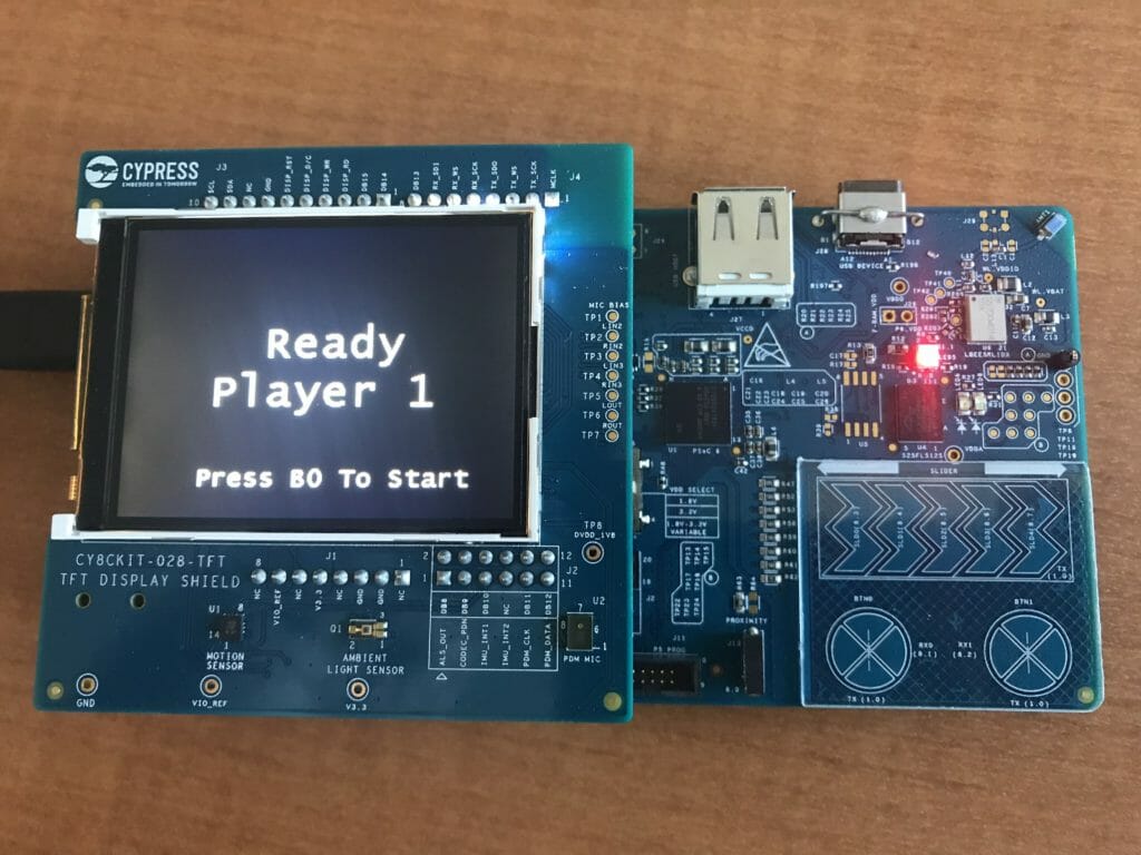
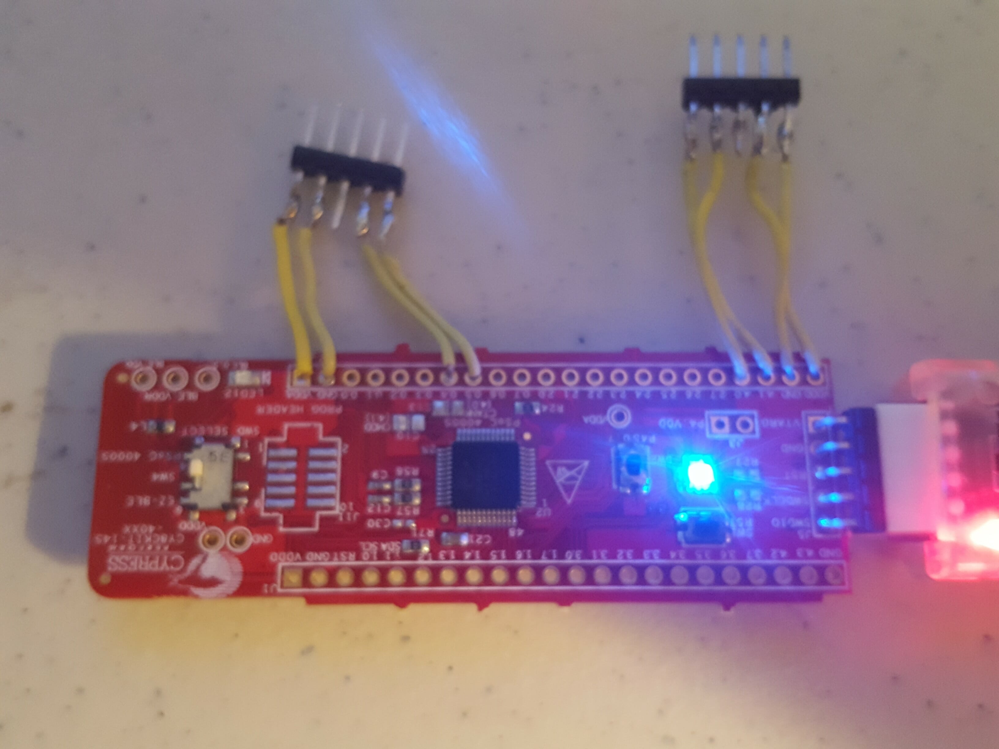
All that being said, I had not seen a good “machine code 101” tutorial for writing assembly in PSOC Creator on modern ARM M0 processors. So let’s walk through one now. We’ll use a CY8CKIT-145 and blink the LED. It’s just what happens to be laying around on the lab bench. Any PSOC4 kit will do.
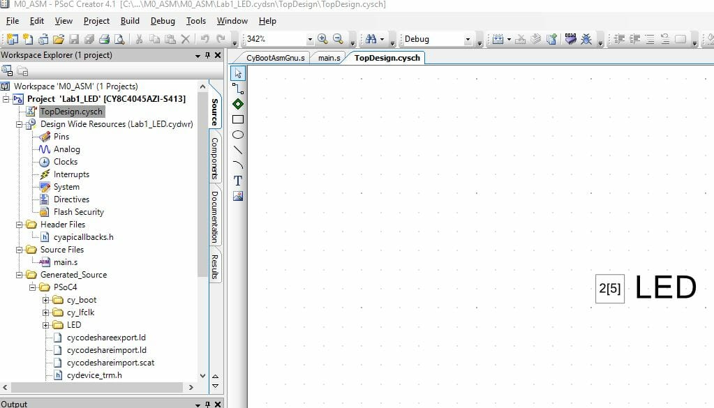
We’ll start by creating a standard project in PSOC Creator, drop a Digital Output pin on the schematic and call it “LED”
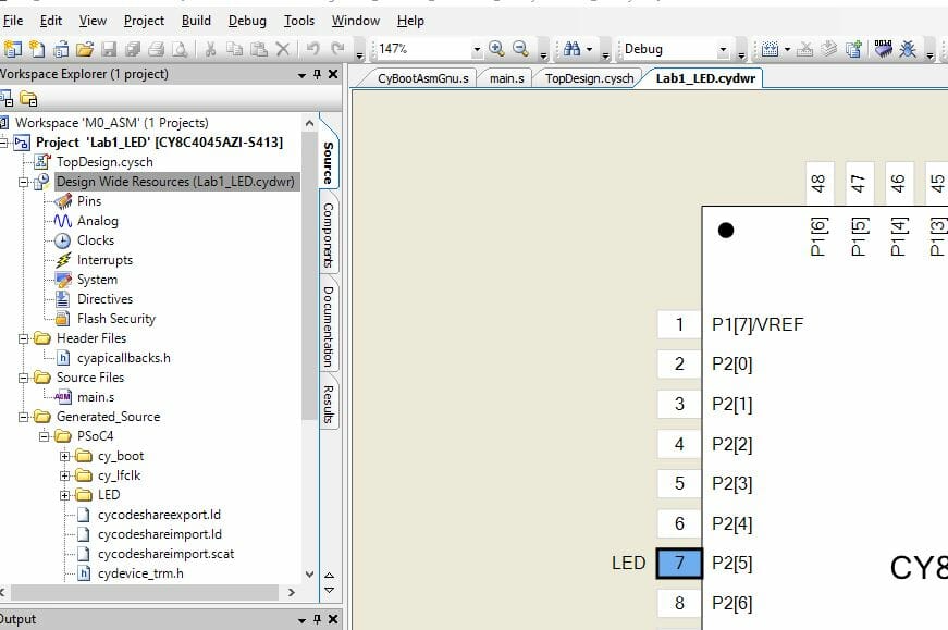
Then open the .CYDWR file and drag pin LED to P2[5], since that’s where it is on the LED board. Yours may be in a different place on whatever board you are using.
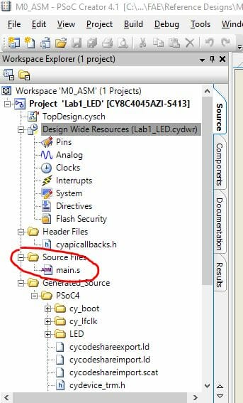
Now under “Source Files” in the workspace directory you will delete main.c and replace with main.s
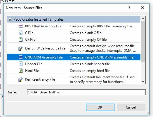
Now right clock on “Source Files”, select “Add New File” and select “GNU ARM Assembly File” in the dialog. Rename the file from GNUArmAssembly01.s to main.s
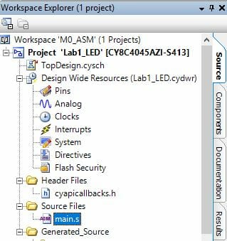
Your workspace ends up looking like this:
So far, so good. Now open main.s, delete everything if it’s not empty and add the following code. This sets up the IDE for M0 assembly architecture
// ==============================================
// ARM M0 Assembly Tutorial
//
// 01 – Blink LED
// ==============================================
.syntax unified
.text
.thumb
Next we need to include register definitions for the chip we are using. These are all from the PSOC4 Technical Reference Manual (TRM)
// ==============================================
// Includes
// ==============================================
.include “cydevicegnu_trm.inc”
Then we are going to do some .equ statements, same as #define in C. This identifies the Port 2 GPIO data register plus bits for the LED pin in on and off state
// ==============================================
// main
// ==============================================
.global main
.func main, main
.type main, %function
.thumb_func
Finally we add the code for main, which is pretty simple:
main:
ldr r5,=LED_DR // Load GPIO port addr to r5
loop0:
ldr r6,=LED_ON // Move led data to r6
str r6,[r5] // Write r6 data to r5 addr
ldr r0,=0xFFFFFF // Argument passed in r0
bl CyDelayCycles // Delay for N cycles
ldr r6,=LED_OFF // Move led data to r6
str r6,[r5] // Write r6 data to r5 addr
ldr r0,=0xFFFFFF // Argument passed in r0
bl CyDelayCycles // Delay for N cycles
b loop0 // Branch loop0
.endfunc // End of main
.end // End of code
One thing to note: The function CyDelayCycles is defined CyBootAsmGnu.s. Any function in assembly gets its arguments passed by the first 4 registers r0,r1,r2 and r3. Before calling the function you simply load r0 with the argument then do a bl (branch with link). This is also why I avoided the first 4 registers when messing with LED data. If you’re interested in doing more with ARM assembly, definitely read the Cortex M0+ Technical Reference Manual. It’s a great primer for the M0+ instruction set.
That’s it. End result is a blinking LED. Cool thing is you can use PSOC Creator with all it’s nice features, but sill access the power of machine code.
I use PSOC4 to invent all kinds of unique solutions for customers. Usually, they want them field upgradeable to deploy new features or fix bugs. Fortunately Cypress has a great I2C boot loader to meet this need, so I use the heck out of it.
Cypress has a great debugger built into PSOC Creator which fully supports all the ARM Serial Wire Debug protocols such as breakpoints, single step, memory, register viewing etc. However, when you are running a boot loader the debugger does not work! Why not? Because with a boot loader there are two applications resident in PSOC4: The boot loader and application. This is not supported by Cypress implementation of SWD.
Where does this leave you, the intrepid code developer, when debugging a boot loader project? Personally, I have used all kinds of methods: debug UART interface, debug I2C interface, bang out states on pins, debug Bluetooth interface … and on and on. You get the idea. All these methods burn a communications interface and require extra pins on the chip. Sometimes that’s not possible.
The issue recently came to a head when a customer very nearly in production experienced a boot loader failure. One system out of a few thousand was “bricked” when they tried to field update in the lab. Their pinout is frozen, they can’t add new hardware so how do we look inside PSOC4 and see what’s going on?
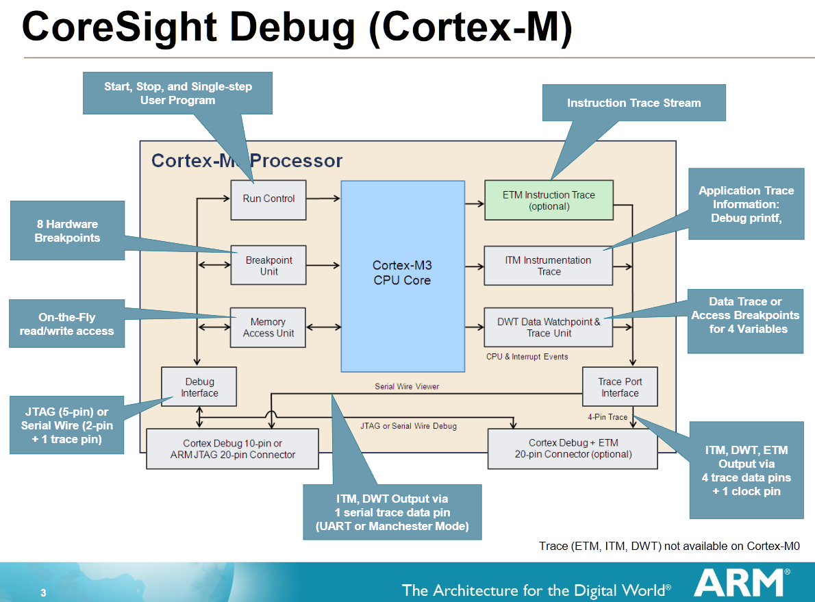
I woke up at 2 AM and thought “Ah Ha! SWV!” (Yes, I Am A Geek) Serial Wire View is an ARM native debug protocol that let’s you XRAY the insides of any ARM MCU with the right interface. SWV is a protocol which runs on the SWD pins (clock and data) but also needs the Serial Wire Output (SWO) pin. Cypress left the SWO pin and associated IP off of PSOC4 to save die cost, foiling my great idea. Brief interlude to drink and bang head on desk.
Fortunately, I don’t give up easily. At least my subconscious does not. Woke up the next night thinking “Ah Ha!” again. Wife was mildly annoyed, but tolerates my idiosyncrasies.
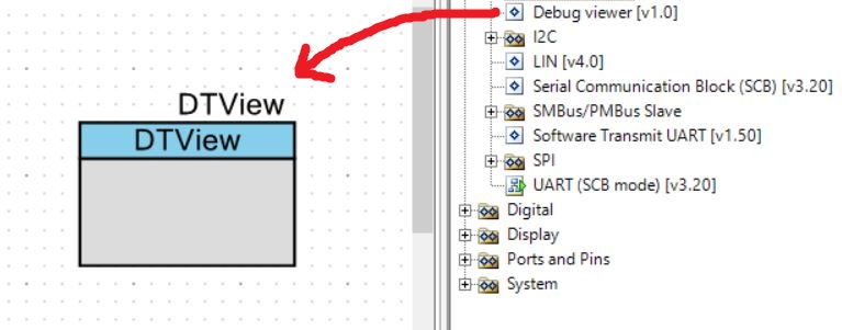
Cypress has a nice software UART transmitter implementation. I shamelessly stole it, modified for my purposes and created a custom component. (It’s pretty easy to do this by the way) Baud rate was modified to 230 KBps and the output pin forced to a specific pin with a control file.
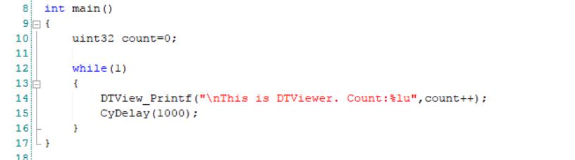
Once the component is in place, you can use its _DView_Printf( ) API call to display any debug data. Here is an example:
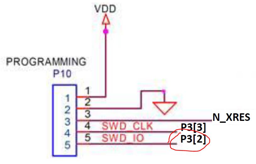
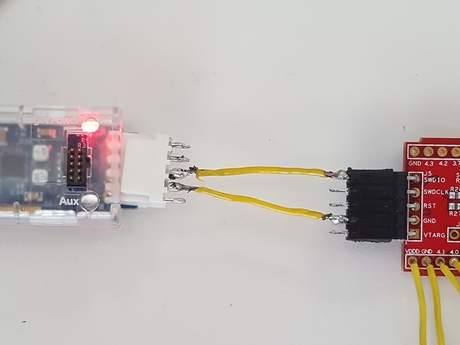
More about that output pin. Cypress sells a tool for programming and debugging PSOC called CY8CKIT-002, aka MiniProg3. The programming connector consists of VDD, GND, reset, SWD clock and SWD data as shown below.
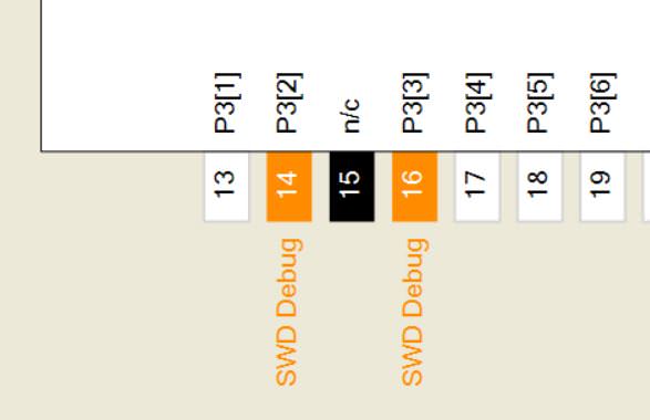
Since we can’t use SWD protocol for debugging anyway, we can change the pins from SWD to normal GPIO. The pins still function for programming. By default they are in SWD mode as shown.
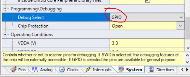
Going to the system tab of the .CYDWR file, we can change them to GPIO.
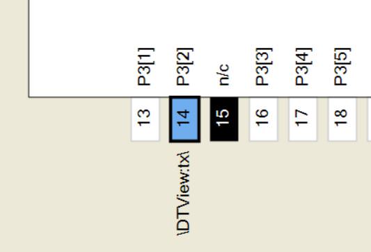
Once we do that, the pins look like this. Here’s the trick. We now assign the TX output of our DTView component to pin 3[2], which is available on the SWD programming header, pin 5.
Can you see where we are going with this? Printf( ) data is now coming out of PSOC4 on pin 3[2], easily accessible on our debug header. This is where MiniProg3 comes in. It can actually receive data as a 230 KBps RX UART on its XRES pin. Weird, right? By building a simple interface cable we can get the data from your debug header into MiniProg3.
MiniProg3 XRES —— SWD HEADER pin 5
MiniProg3 GND —— SWD HEADER pin 2
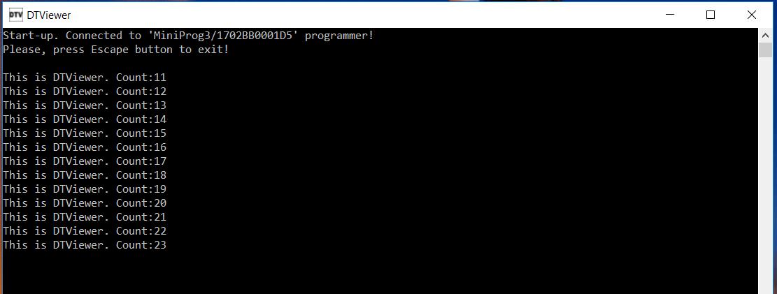
However, MiniProg3 does not show up as a COM port on your PC, so how do we the data? It needs to be accessed by a host application running the PP_COM API. This is documented under PSOC Programmer Component Object Model COM Interface Guide, Cypress specification 001-45209. If you installed PSOC Creator or Programmer, this document is actually on your PC under C:\Program Files (x86)\Cypress\Programmer\Documents. Engineers don’t like to read instructions. Amazing what you can find when you do.
I wrote a simple console application which opens MiniProg3 using PP_COM, retrieves data from the serial RX pin via USB and displays it like a simple terminal program. Voila! You now have a serial debugger that works for any PSOC4 project using MiniProg3 as your USB to serial dongle.
Customer was really happy with this. We were able to immediately see his problem and fixed it in about 5 minutes.
Finally, here are all the source files
DTView Firmware : PSOC Creator example project and DTView component
In the last Article I talked about the GE Megahackathon. One of the groups at the event got interested in using a CY3280 MBR3 to send signals via a WICED CYW943907 to the Particle IO server which was connected to a Particle Photon. I helped them with the implementation and thought that it would be useful to show here.
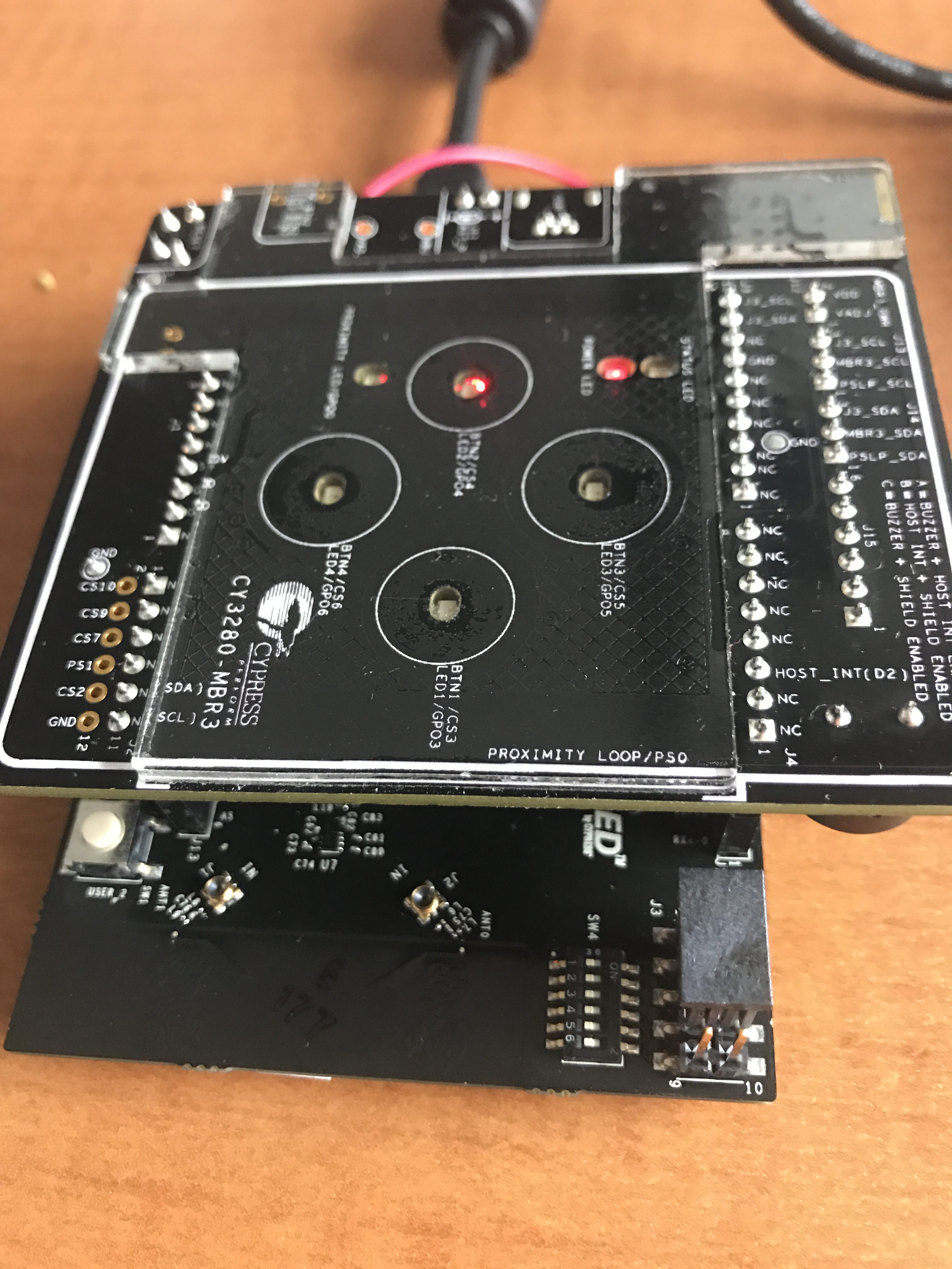
Cypress CY3280 MBR3
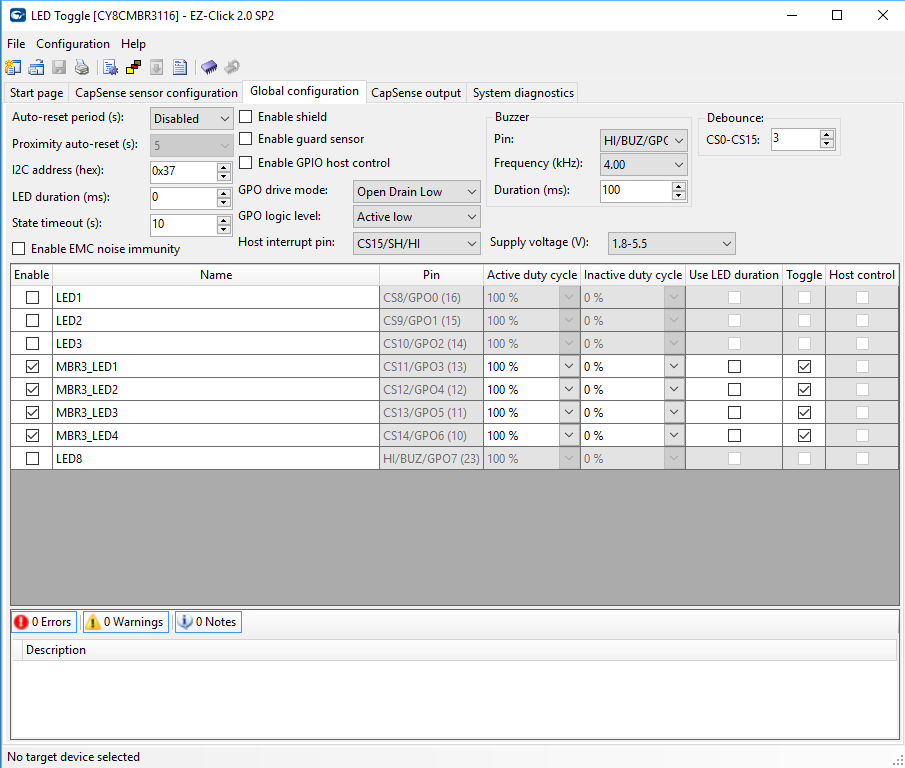
The CY3280 MBR development kit is a CapSense demonstration kit that shows the Mechanical Button Replacement 3 chip. It features 4 CapSense buttons with LEDs, a proximity sensor, and a buzzer. It is connected to another MCU via the Arduino pins. of the WICED CYW943907. The device sits on the I2C bus and acts as an I2C Slave. You configure it using EZ Click.
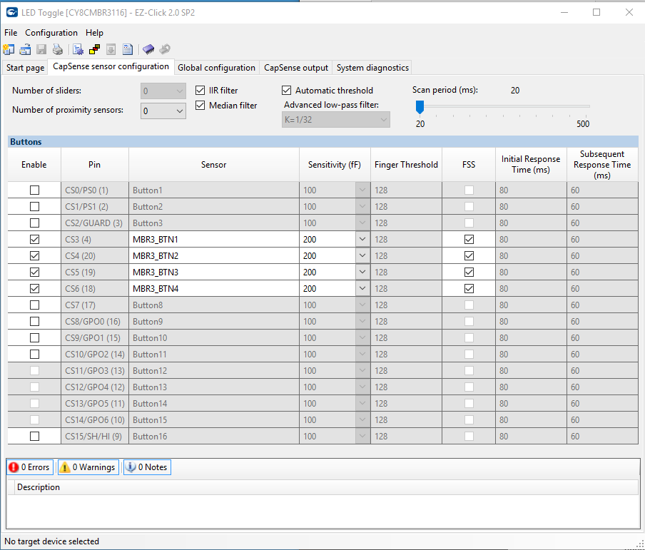
When you run EZ Click you can setup the configure the internal registers of the MBR3 to make the board act like a bunch of different things. In this case I turned on
The MBR buttons 1-4 (you can see them in the picture above)
The Flanking Sensor rejection which makes it so that you can only press one button at a time.
All of the automatic tuning features.
Once the main CapSense is configured, I moved to the other part of the configuration where I setup
The 4 LEDs to toggle and be full brightness when on
The buzzer to buzz for 100ms at 4kHz when something happens
The host interrupt pin as CS15/SH/HI. This made the Arduino pin D2 be an interrupt when something happened so that WICED would poll the MBR3
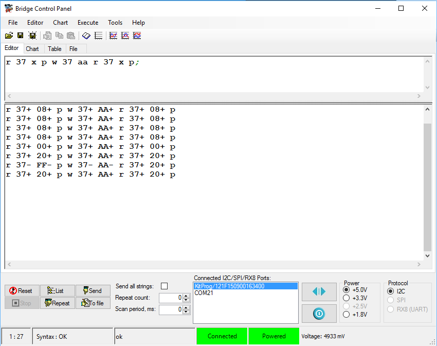
Once these settings were all done, I downloaded the firmware configuration via the KitProg USB connector. Then I tested it using the bridge control panel which I have shown you a bunch of different times in the past. The MBR3 acts as an I2C slave. To find out what the state of the buttons are you need to read register 0xAA. The only little trick is that the chip goes to sleep to save power. In order to wake it up you need to send an I2C transaction, which ends up getting NAK’d. But the next transaction you send will be ACKd. In the screenshot below you can see that I tried two of the buttons (0x08 and 0x20)
One problem that I had is that the power system of this board is setup to take 5V from the Arduino base board but the WICED development kit gives only 3.3v. Here is a picture of the power system from the MBR3 schematic.
The MBR3 can run on 3.3Vs. In fact it can run all the way down to 1.7v and up to 5.5v, but for some reason (which I can’t remember) we made the board only work with 5.0v. To fix this problem I removed J12 and then wired a wire from the 3.3V Arduino pin. The wire is soldered onto the 3.3v pin, but has a female connector on the other side so that it can be plugged into J12. Here is a picture:
The last thing that I needed to do was move the jumpers to position “A” which made the host interrupt pin be connected to D2, and move the I2C jumpers so that the MBR3 was connected to the Arduino instead of the P5LP kitprog. You can see that in the J3_scl and J3_sda in the picture above.
WICED CYW943907
The CYW934907AEVAL1F is an development kit for the Cypress 43907 MCU+WiFi module. The WICED CYW943907 board can do dual band (2.4 and 5Ghz), 802.11 a/b/g/n, Ethernet and a whole bunch of other stuff.
The first firmware that I wrote in WICED Studio:
Sets up an ISR to unlock a semaphore when the interrupt occurs
Initialized WICED_GPIO_9 to be an input and connected to an ISR … this is also known as Arduino D2
Setup the I2C Master Hardware in the 43907
Wait for a semaphore (from the ISR)
Read the I2C register 0xAA from the MBR
The only trick in the firmware is that I read the I2C with a “do” loop until I get a valid result, meaning that the MBR3 has woken up.
#include "wiced.h"
#define I2C_ADDRESS (0x37)
#define BUTTON_REG (0xAA)
wiced_semaphore_t buttonPress;
/* Interrupt service routine for the button */
void button_isr(void* arg)
{
wiced_rtos_set_semaphore(&buttonPress);
}
/* Main application */
void application_start( )
{
wiced_init(); /* Initialize the WICED device */
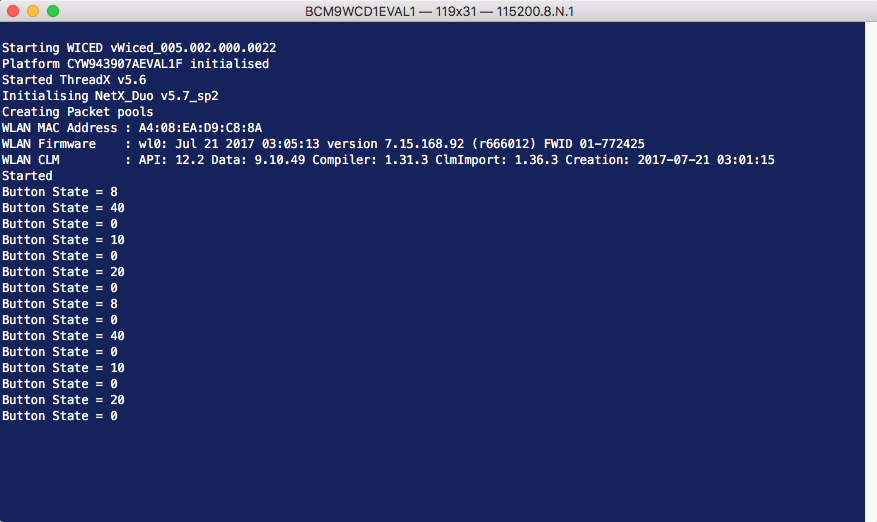
WPRINT_APP_INFO(("Started\n"));
wiced_result_t result;
wiced_rtos_init_semaphore(&buttonPress);
// WICED_GPIO_9 is the MBR3 Interrupt Pin
wiced_gpio_init(WICED_GPIO_9,INPUT_PULL_UP);
wiced_gpio_input_irq_enable(WICED_GPIO_9, IRQ_TRIGGER_FALLING_EDGE, button_isr, NULL); /* Setup interrupt */
/* Setup I2C master */
const wiced_i2c_device_t i2cDevice = {
.port = WICED_I2C_2,
.address = I2C_ADDRESS,
.address_width = I2C_ADDRESS_WIDTH_7BIT,
.speed_mode = I2C_STANDARD_SPEED_MODE
};
wiced_i2c_init(&i2cDevice);
/* Tx buffer is used to set the offset */
uint8_t tx_buffer[] = {BUTTON_REG};
uint8_t buttonStatus;
while ( 1 )
{
wiced_rtos_get_semaphore(&buttonPress,WICED_WAIT_FOREVER);
// Do this until the MBR3 is alive. It goes into deep sleep and wakes when you
// send the first command.
do {
result = wiced_i2c_write(&i2cDevice, WICED_I2C_START_FLAG | WICED_I2C_STOP_FLAG, tx_buffer, sizeof(tx_buffer));
}
while(result != WICED_SUCCESS);
result=wiced_i2c_read(&i2cDevice, WICED_I2C_START_FLAG | WICED_I2C_STOP_FLAG, &buttonStatus, sizeof(buttonStatus));
WPRINT_APP_INFO(("Button State = %X\n", buttonStatus)); /* Print data to terminal */
}
}
Once that is programmed I program and test the firmware.
In the next article I will modify all of this firmware and make the WICED CYW943907 send data via HTTP to the Cloud.
In the last article I showed you clever FreeRTOS PSoC Component… and the talked about some of the issues that I had with it. In this article I will talk about a self-contained FreeRTOS PSoC Template project that includes everything for FreeRTOS and Tracealyzer all in one project. My idea was that when I start a new project I will just make a copy of the template project, rename it, then move on.
My FreeRTOS PSoC Template has
FreeRTOS with the files in in the same directory (i.e. not referenced externally)
Tracealyzer with the files in the same directory & all of the streamports including RTT and the UART DMA
All of the files organized into PSoC Creator folders
A template main.c
All of the build settings configured
This project is checked into GitHub and you can find it git@github.com:iotexpert/PSoC-FreeRTOS-Template.git
Building the FreeRTOS PSoC Template
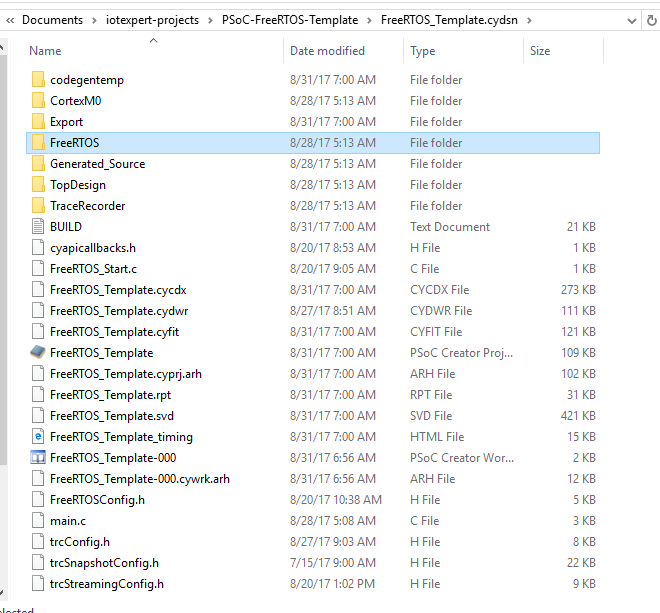
I started the process by creating a blank PSoC project called “FreeRTOS_Template”. I then went into the Windows Explorer and copied the entire FreeRTOS source directory into the FreeRTOS PSoC Template Project directory. Then I copied the Percepio TraceRecorder library into the FreeRTOS PSoC Template project.
By having both of the source directories in my project it isolated this project from changes in the FreeRTOS or the TraceRecorder. Obviously that is a double edged sword. The next thing that I did was use the Windows Explorer to copy FreeRTOSConfig.h, trcConfig.h, trcSnapshotConfig.h and trcStreamingConfig.h into the project. Once all of the files were in my project directory is was time to fix up the PSoC Creator Project.
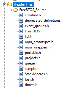
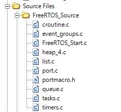
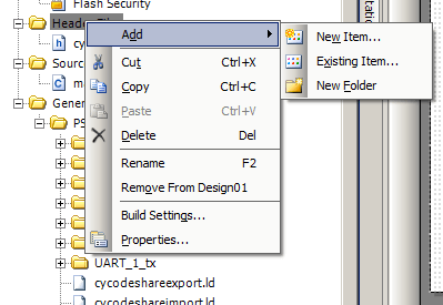
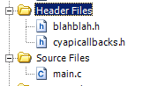
To do this I created a folder called “FreeRTOS_Source” in the “Header Files” and “Source Files” folders in my template project. You can do this by right clicking and selecting “Add->New Folder”. Then I added all of the appropriate .h and .c files from FreeRTOS source directory. This gives me the following project view:
And Source Files (notice that I also added heap_4.c which I generally use for memory management)
Then I add the configuration files FreeRTOSConfig.h, trcConfig.h, trcSnapshotConfig.h, trcStreamingConfig.h and trcStreamingport.h. Next I do the same thing for the TraceRecorder library which makes my project look like this:
Then I modify the build settings to add the include directories:
Now you can modify the FreeRTOSConfig.h to include all of the Tracealyzer stuff:
/* A header file that defines trace macro can be included here. */
#if ( configUSE_TRACE_FACILITY == 1 )
#include "trcRecorder.h"
#endif

#endif /* FREERTOS_CONFIG_H */
Then I setup a new tab in the schematic to contain the DMA UART Streamport. You can read all about the UART DMA Streamport in this article.
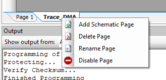
By putting that part of the stream port on a separate schematic page I can now do a right click and disable the page when I am not using the Tracealyzer streamport. Disabling a page of the schematic completely removes everything from the build.
Next I create files called FreeRTOS_Start.h/.c to put in the startup code:
Finally I make a template main.c that starts everything and has a simple ledTask and instructions for changing Memory Management scheme and the TraceRecorder.
// This template has heap_4.c included in the project.  If you want a
// different heap scheme then remove heap_4 from the project and add
// the other scheme from FreeRTOS/Source/portable/memmag

// TraceRecorder
// There are methods
// 1. Snapshot mode
// 2. Streaming UART/DMA
// 3. Streaming JLINK RTT
//
// To use method 1:
// - in FreeRTOSConfig.h make this line be 1 (currently line 45)
//#define configUSE_TRACE_FACILITY                1
// - in trcConfig.h configure the TRC_CFG_RECORDER
// #define TRC_CFG_RECORDER_MODE TRC_RECORDER_MODE_SNAPSHOT
//
// To use method 2:
// - in FreeRTOSConfig.h make this line be 1 (currently line 45)
//#define configUSE_TRACE_FACILITY                1
// - in trcConfig.h configure the TRC_CFG_RECORDER
//#define TRC_CFG_RECORDER_MODE TRC_RECORDER_MODE_STREAMING
//
// This project currently has the PSoC UART Streaming Port
// add the TraceRecorder/streamports/PSoC_Serial/trcStreamingPort.c to the project
// add the TraceRecorder/streamports/PSoC_Serial/include/trcStreamingPort.h
// add the TraceRecorder/streamports/PSoC_Serial/include to the compiler include directories
// Enable the Trace_DMA schematic sheet and make sure UART pins are assigned correctly
// This port depends on the UART being named UART and the DMA being named "DMA"
//
// To use method 3: JLINK RTT
// Remove the previous streamport files from the project
// Remove the Streamport include path
// add the TraceRecorder/streamports/JLink_RTT/Segger_RTT.c to the project
// add the TraceRecorder/streamports/JLink_RTT/Segger_RTT_Printf.c to the project
// add the TraceRecorder/streamports/JLink_RTT/include/trcStreamingPort.h
// add the TraceRecorder/streamports/JLink_RTT/include/Segger_RTT.h
// add the TraceRecorder/streamports/JLink_RTT/include/Segger_RTT_Conf.h
// add the TraceRecorder/streamports/JLink_RTT/include to the compiler include directories


#include "project.h"
#include "FreeRTOS.h"
#include "timers.h"

// An example Task
void ledTask(void *arg)
{
    (void)arg;
    while(1)
    {
        RED_Write(~RED_Read());
        vTaskDelay(500);
    }
}

int main(void)
{
    CyGlobalIntEnable;
    FreeRTOS_Start();

    #if ( configUSE_TRACE_FACILITY == 1 )
    vTraceEnable(TRC_START);
    #endif

    xTaskCreate(ledTask,"LED Task",configMINIMAL_STACK_SIZE,0,1,0);
    vTaskStartScheduler();  // Will never return
    while(1);               // Eliminate compiler warning
}
When building a PSoC Creator project there are a number of “sources” of “source code” including:
Cypress PSoC Component Code from the Cypress Component Library (which end up in the Generated_Source directory)
Your C Source code files .h/.c e.g main.c
Your Components from your Component Library (which end up in the Generated Source Source directory)
Other Libraries of code (e.g. FreeRTOS or Percepio Tracelyzer)
There are (at least) five tools which need to “know” about where the source code for your project resides including:
Workspace Explorer (so you can browse the files and open the code in an editor)
PSoC Creator Code Editor (so Intellisense works correctly)
GCC Compiler
Linker
Debugger
Here is a video where I talk about the files structure of PSoC Creator Projects:
PSoC Creator takes care of so many of these details automatically for you, so I have not put much thought into how these things work. But, in the last few months, I have been building projects that use FreeRTOS, which has made me contemplate how things go together. This is the genesis of this Article.
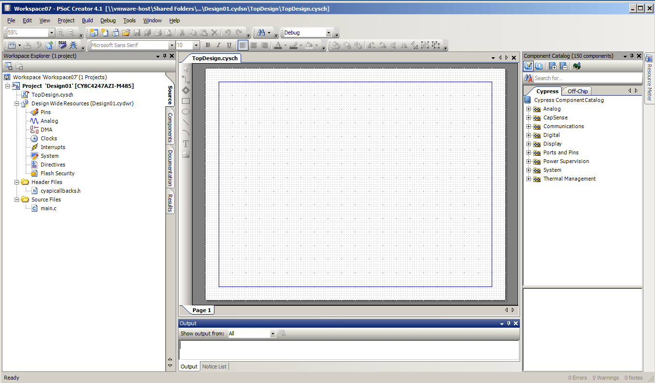
Lets start with a blank project (which I created for the CY8CKIT-044). When you make this project you can see that you get:
A Workspace (called Workspace07) that contains one project. The name is just a default name + a number that Creator made for you.
A Project (called Design01)
A Schematic (called TopDesign.cysch)
Design Wide Resources (called Design01.cydwr)
A folder for Header Files which contains a file called cyapicallbacks.h
A folder for Source Files that contains main.c
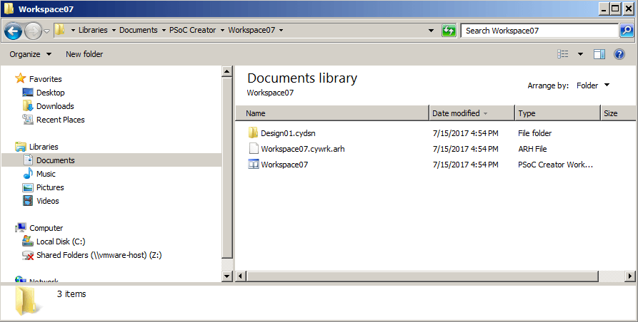
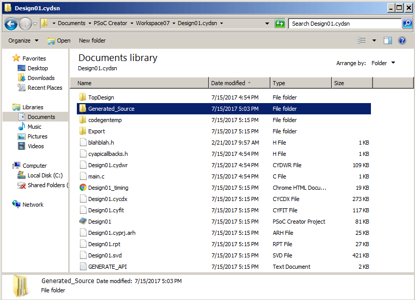
When you look at the disk you will see a directory at the top level called “Workspace07”. This directory contains:
The workspace file called Workspace07.cywrk and a user specific settings file called Workspace07.cywrk.arh (the .arh is my windows login). This binary file contains references to all of the projects that are part of the Workspace. Plus other Workspace configuration.
A directory called “Design01.cydsn”. This directory contains everything required for the project.
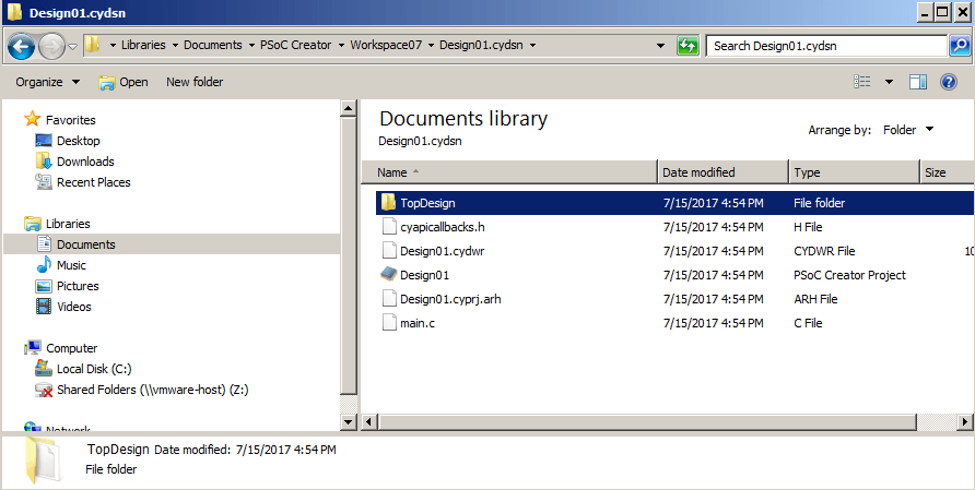
When I look in the directory called “Design01.cydsn” I see
Design01.cyprj (an xml file that contains all of the information about the project)
Design01.cydwr (an xml file that contains all of the Design Wide Resource settings)
The two source files main.c and cyapicallbacks.h
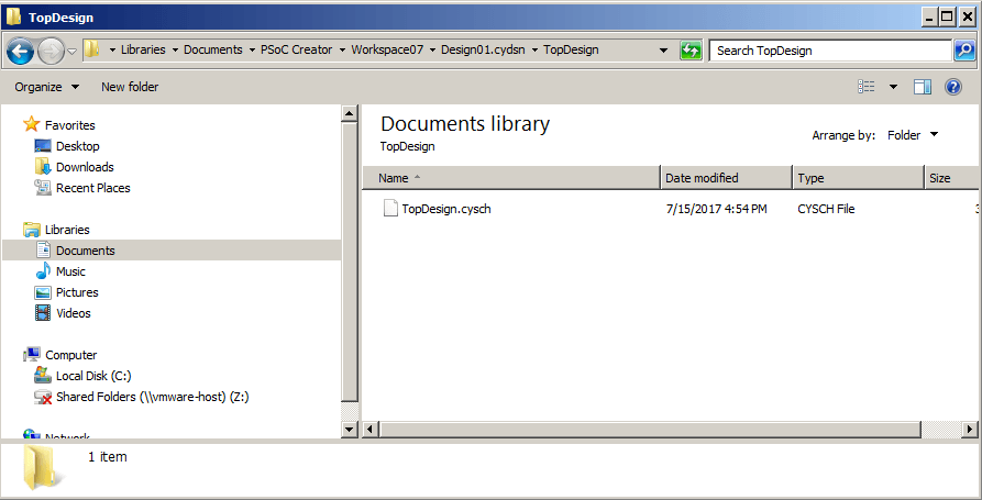
A directory called “TopDesign”
In the TopDesign directory you will find the TopDesign.cysch which is the binary file of the schematic.
Now that we have accounted for all of the “basic” project stuff. I will run “Generate Application” from the build menu.
Cypress PSoC Creator Components
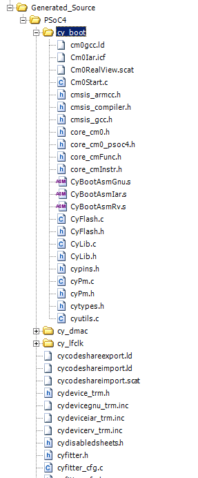
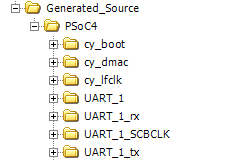
After the Application Generation is done you will see a bunch of more stuff in the Workspace Explorer. Specifically a new folder called “Generated_Source”. In that folder you will see a folder called “PSoC4” that contains a bunch of files plus some more folders. These folders are created by the application generation process to hold the source code for components including cy_boot, cy_dmac, and cy_lfclk. But you say, “I didn’t place any components”, and that is true, but PSoC Creator did this automatically for you when you made the project. These source files are used to get the PSoC booted, the linker setup, the CMSIS core definitions etc.
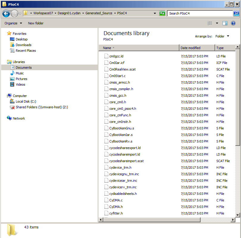
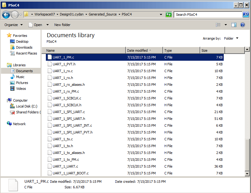
When you look on the disk, you will see a completely different hierarchy than you see in the Workspace Explorer. In fact you will see all of these files in a directory called “Generated_Source/PSoC4”. This tells us something important. The workspace explorer gives you hierarchy so that you can see the different files grouped together logically. BUT this hierarchy is completely unrelated to how the build process works (more on this in a minute) or how the files reside on the disk. DANGER DANGER WILL ROGERS!!! (these Folders are actually called “Filter Folders” and you can read about them in the PSoC Help Topic “Creating Folders”)
When you place a component in the schematic (e.g. a UART) and run the build again you will find more folders & files in the Generated_Source section of the Workspace Explorer
But when you look in Generated_Source directory on the disk, you will find ALL of those files in one directory.
When you place a component, PSoC Creator takes the API from the Component Library, processes it, names it correctly, adds it to your “.cyprj” file so that the Workspace Explorer can see it, then copies the code into your Generated_Source directory. You could edit it there, but if you do, you are at risk to having it overwritten the next time you build the project. All of the configuration you do to a component gets turned into c-source that resides in the Generated_Source directory
When you delete a component, the related generated source code (e.g., UART_1.*) won’t be visible in Workspace Explorer, but IT STILL LIVES ON DISK. This is a consequence of our legacy “merge region” support. The user may have edited the file and PSoC Creator doesn’t want to destroy those edits. This can cause inconsistencies between what Workspace Explorer shows the user and what the compiler actually sees:
PSoC Creator will NOT compile any irrelevant .c files present in the file system.
However, the compiler WILL see any stale .h files that happen to be lying around when it processes #includes.
So, what is a merge region? When PSoC Creator was originally created, it was recognized that there was occasionally need for a user to put code into a generated file e.g. an interrupt handler. And we also wanted PSoC Creator to be able to regenerate that file. If you look around in Generated_Source files, you will find sections of code that look like lines 27-30. If you put code between those funny looking comments, it will not be blown away when you regenerate your application. In other words PSoC Creator preserves all of the code in merge regions. This mode has mostly be supplanted by the use of the “cyapicallbacks.h” functionality.
/*******************************************************************************
* Function Name: isr_1_Interrupt
********************************************************************************
*
* Summary:
*   The default Interrupt Service Routine for isr_1.
*
*   Add custom code between the START and END comments to keep the next version
*   of this file from over-writing your code.
*
*   Note You may use either the default ISR by using this API, or you may define
*   your own separate ISR through ISR_StartEx().
*
* Parameters:
*   None
*
* Return:
*   None
*
*******************************************************************************/
CY_ISR(isr_1_Interrupt)
{
    #ifdef isr_1_INTERRUPT_INTERRUPT_CALLBACK
        isr_1_Interrupt_InterruptCallback();
    #endif /* isr_1_INTERRUPT_INTERRUPT_CALLBACK */

    /*  Place your Interrupt code here. */
    /* `#START isr_1_Interrupt` */

    /* `#END` */
}
Your Code in C Source Files (.h/.c)
All of the files in “Header Files” and “Source Files” are considered to be owned by you. In other words, PSoC Creator will never make changes to those files. PSoC Creator starts by giving you copies of two template files, main.c and cyapicallbacks.h. These files are yours to edit and you are responsible for the contents.
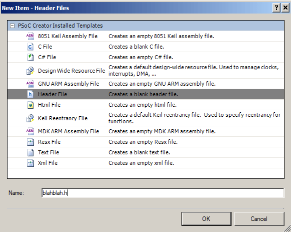
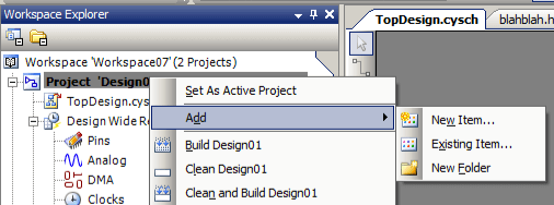
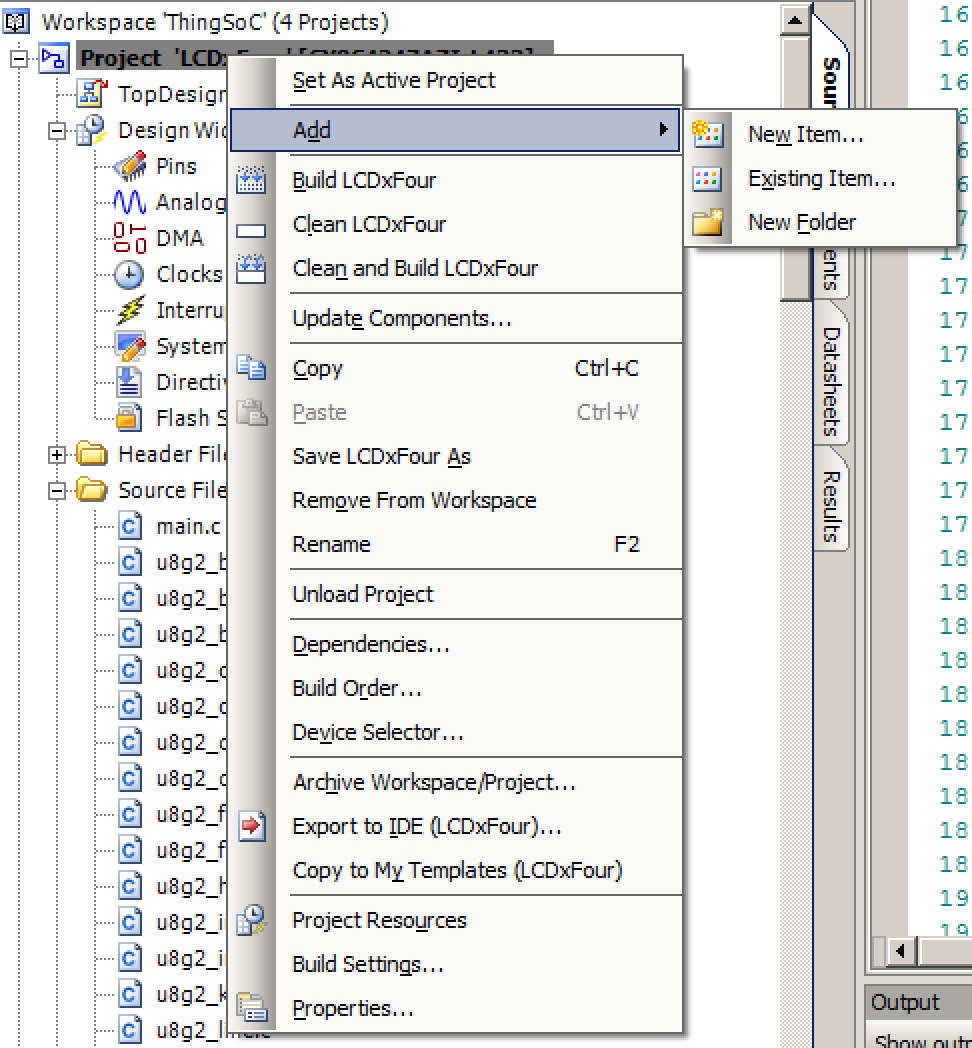
If you are making a project that is to big to logically fit into just main.c you may want to split it up into multiple .c and .h file. You can do this by adding .c and .h source files to your project. Right click the “Header Files” folder (or “Source Files”) and select “New Item”
Then enter the name of the file and select the FileType (in this case I did “blahblah.h”)
After doing that I will have a new file in the Workspace Explorer
Plus I will have the same file in the Design01.cydsn directory
All of the files that I add by doing “New Item” will end up in the “right” folder and reside in the project directory on the disk.
Your Components
In PSoC Creator, it is possible to create your own Components. You can read or watch videos about this process
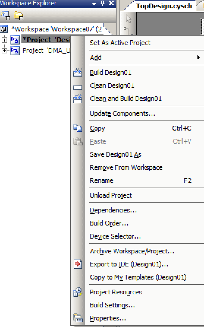
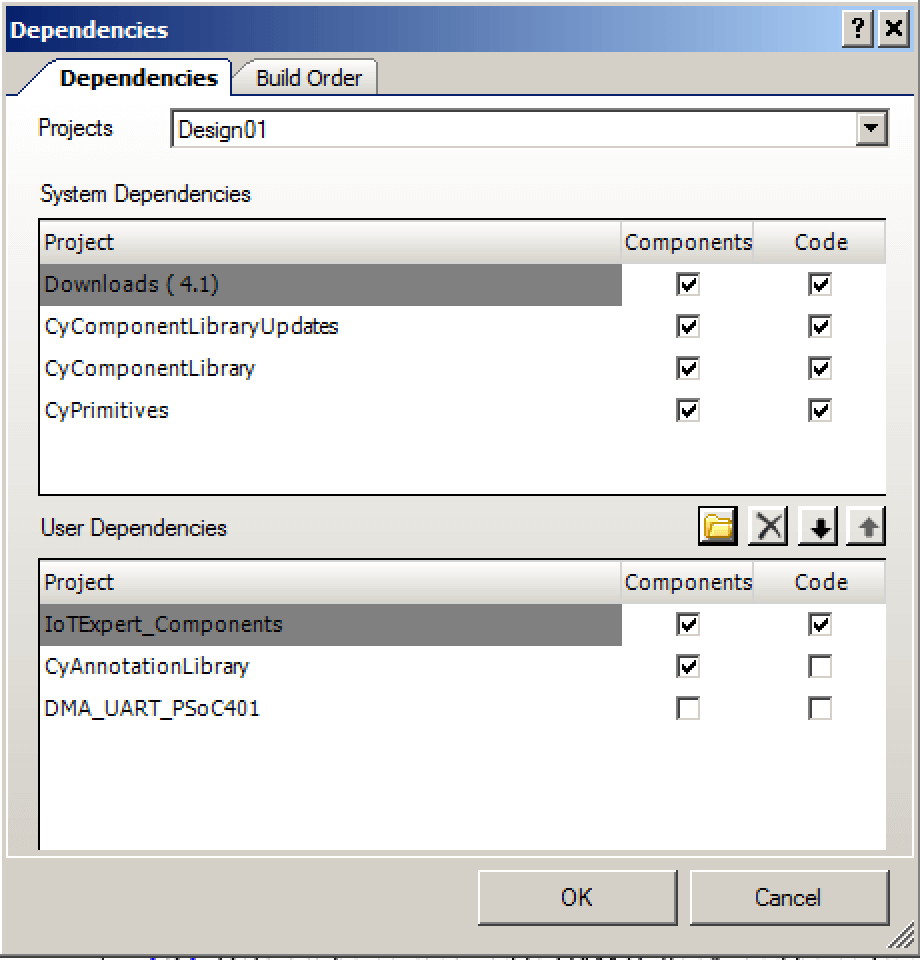
After you have a library with Custom Components, you can add it as a dependency to your project by right clicking on the project and selecting “Dependencies …” Then navigating to the .cyprj file with your components. In this case I added the IoTExpert_PSoC_Components library
You can see that the “IoTExpert_Components” shows up in the User Dependencies
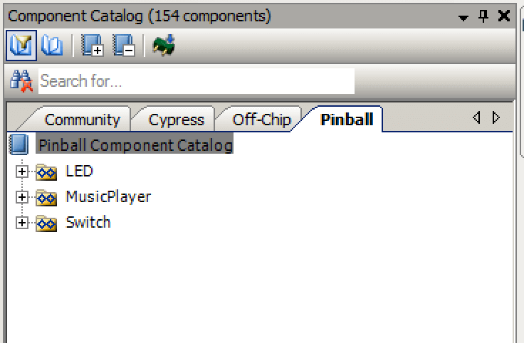
Once this is done you will see the new Component Libraries in the Component Catalog.
Components from your custom libraries act exactly the same as the Cypress Components. Specifically, after you place a custom component in your schematic, when you build the project, it will process the source code, copy it into the “Generated_Source” directory, add the files to your WorkSpace Explorer etc.
A custom component is a good way to easily add a library of source code to your project.
3rd Party Libraries
The last class of source code comes from 3rd Party Libraries. Classically, these libraries have one more more directories with .c, .h and .a (static libraries) files. There are some of the files which you might want to modify to configure your version of the library, there are other files that you just need to be compiled into your project. This situation leaves you with some choices.
You can copy all of the library files into your project directory (then add existing item)
You can copy some of the library files into your project directory and leave some of the files in the library directory
You can add references to the library files into your project
The main issue that you need to consider is Source Code Control – Version Management of your project. If you copy the library files into your project directories, then you are sure that they won’t change out from underneath you. BUT, if the library has a bug fix, then you won’t automatically get it. It is often considered a best practice to have a “single source of truth”. When you copy files into your project, you violate that principal. This is a choice that you will need to grapple with.
This is probably best explained with a real example, FreeRTOS. I have been using the hybrid model. Specifically I copy the configuration files into my project, but leave the rest of FreeRTOS in my downloaded directory and use references in my PSoC Creator Project. The process is:
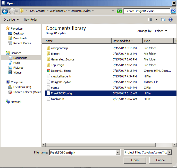
In the Windows Explorer copy FreeRTOSConfig.h into my project directory
Right click the project and “Add Existing Item”
Then select “FreeRTOSConfig.h” from my project directory
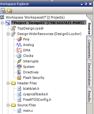
After that you can see that “FreeRTOSConfig.h” is part of my project in the “Header Files” section
I like the rest of the FreeRTOS Files to be part of the project but not actually copied into my project directory. To do this, I add the required C-Files using the same technique of “Add Existing” To make FreeRTOS work you need to add all of the C-Files and H-Files in:
FreeRTOS/Source/portable/GCC/ARM_CM0
FreeRTOS/Source/include
FreeRTOS/Source/
FreeRTOS/Source/portable/MemMang/heap_1.c
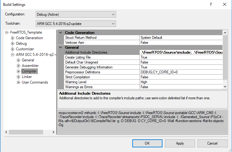
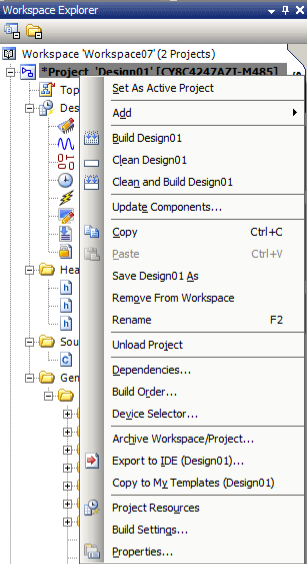
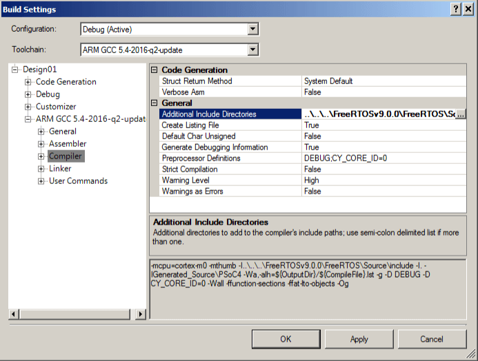
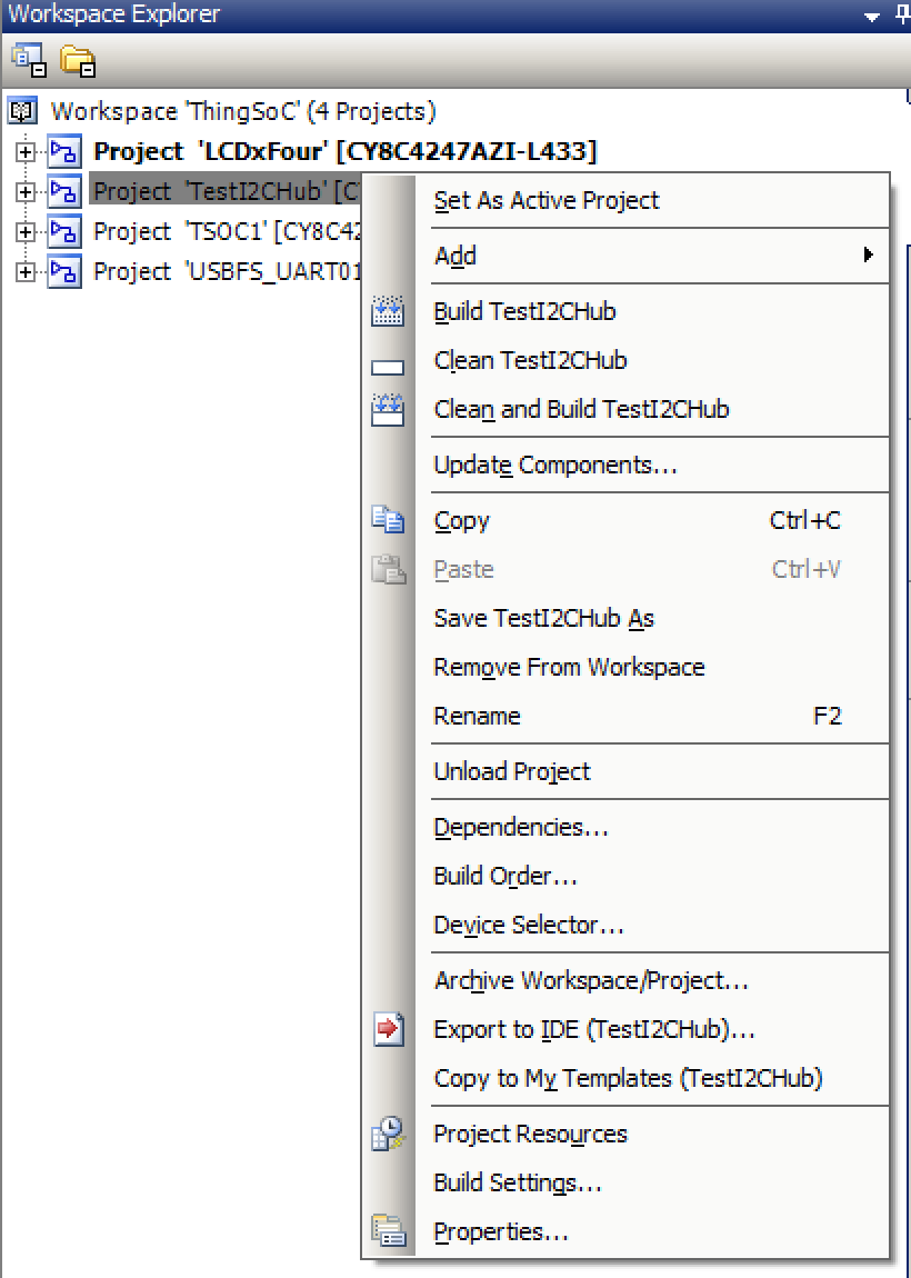
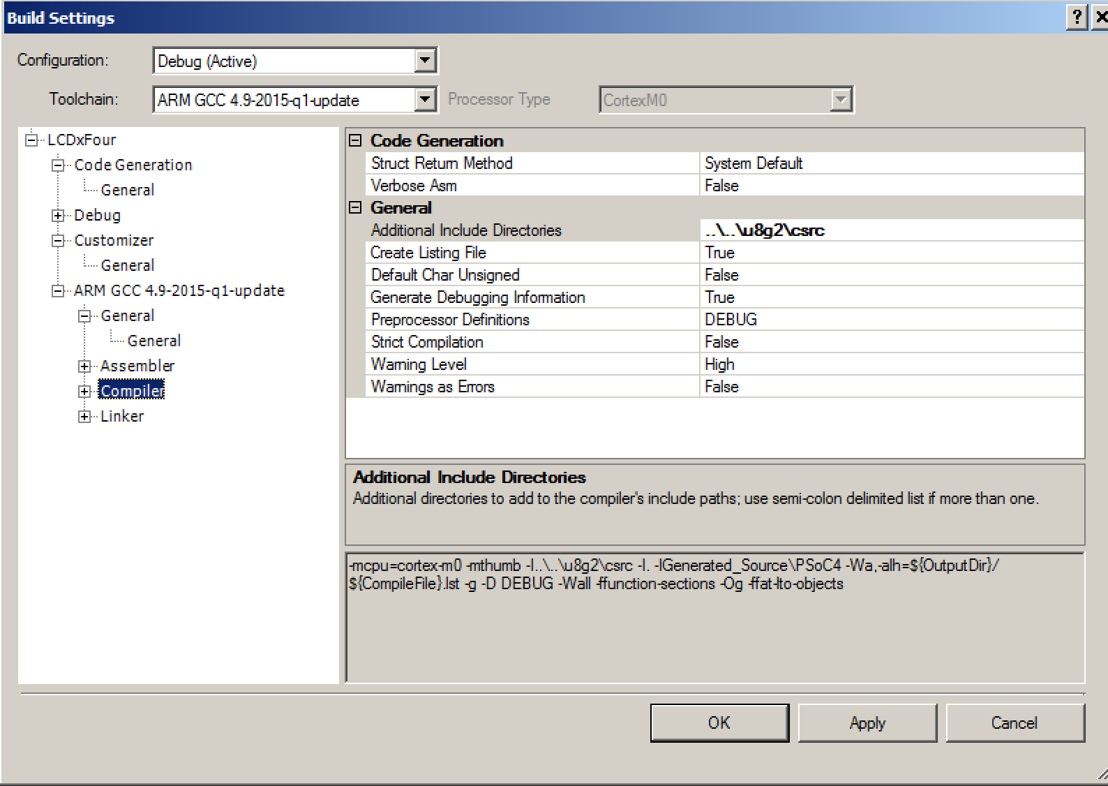
PSoC Creator will automatically take care of telling the compiler where to get the C-Files. However, it will not take care of the H-Files. In order to do this you need to change the build settings to add the path to all of the H-Files that you use. Modify the build settings by right-clicking the project and selecting “Build Settings …”
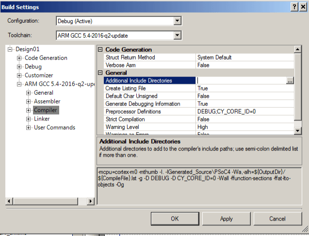
Then selecting the “…” on Design01 –> Arm GCC … –> Compiler –> Additional Include Directories
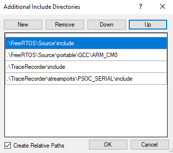
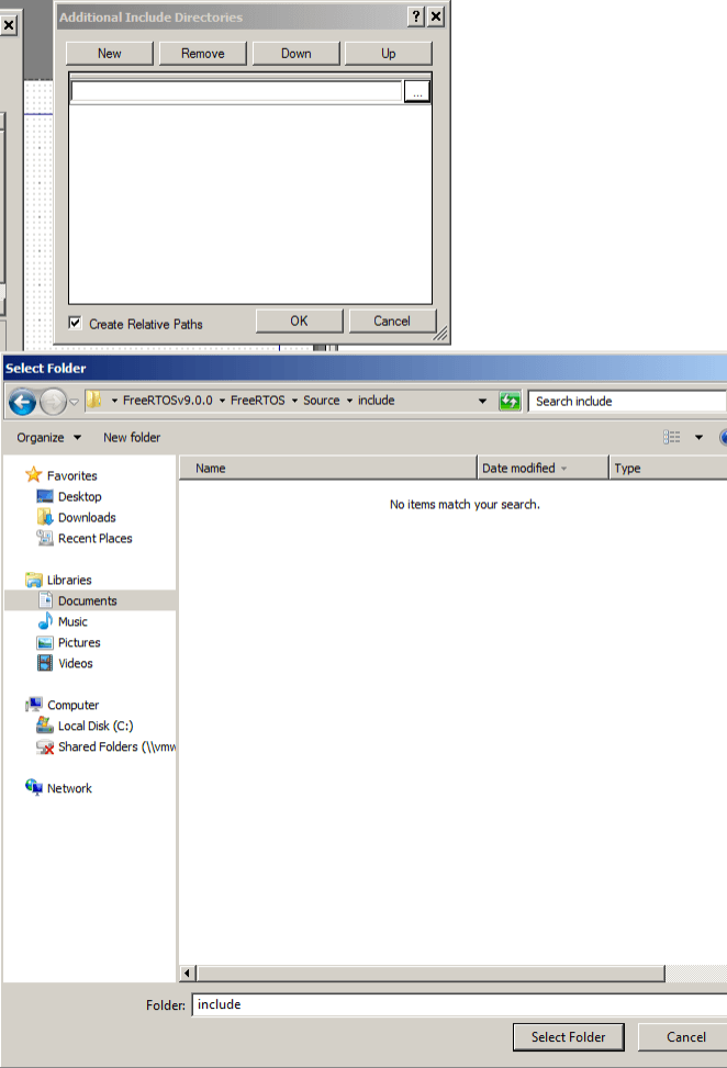
Then press the “New” and then the “…” to browse to the directory you want to add.
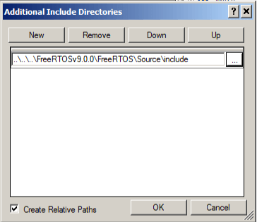
Finally you will end up with a window that looks like this:
And when you look at the build options you will see the “-I..\..\..\FreeRTOSv9.0.0\FreeRTOS\Source\include” is added to the compiler options (look at the little window at the bottom)
Thank you to Nick from the PSoC Creator Team for reviewing my Article. He is one of the lead technical genius’ that made PSoC Creator the bad-ass software that it is.
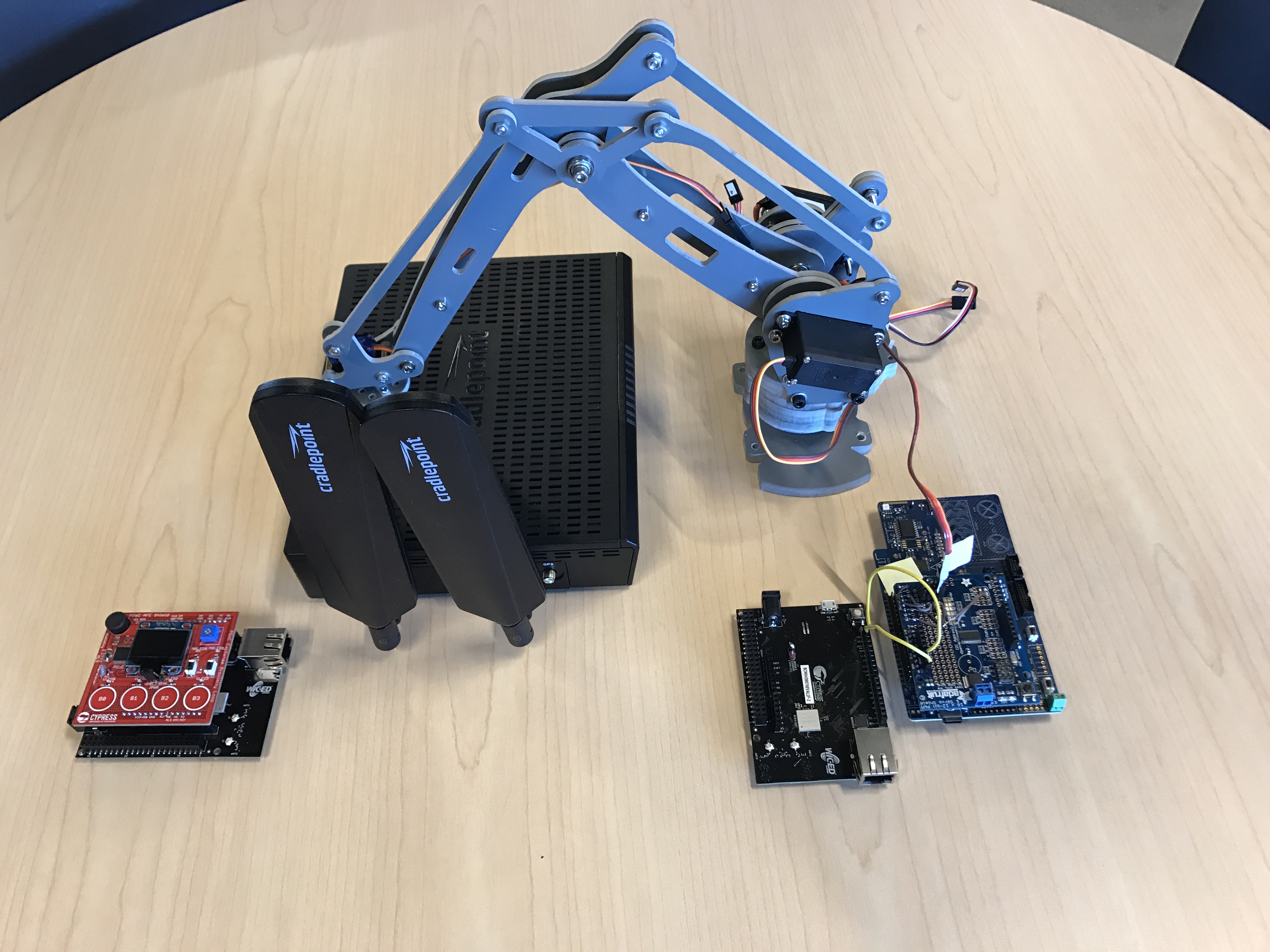
I have been building up pieces of code that are going to allow me to show the PSoC Analog CoProcessor –> WICED WiFi –> Amazon IoT –> WICED WiFi –> Secret New Chip –> Robot Arm. In the previous two articles (part1, part2) I have shown you how to build most of the WICED firmware. In this article I am going to focus on the PSoC Analog CoProcessor firmware (but if you look real close you can see the secret new chip’s development kit).
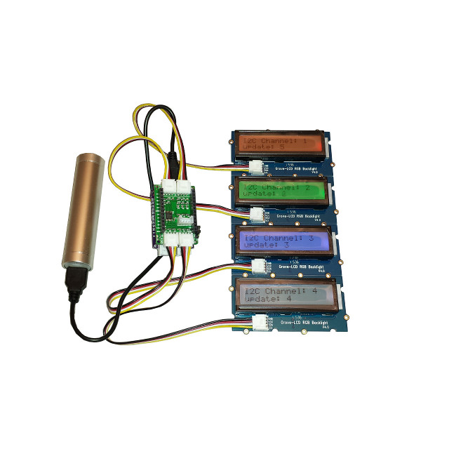
In the picture below you can see the red shield board. This is a shield with the PSoC Analog CoProcessor plus a bunch of sensors that show the power of that chip. The shield also includes 4x CapSense Buttons which I am going to use to set the position of the Robot Arm. The PSoC will serve as a front end companion to the WICED WiFi Development Kit. They will communicate via I2C with the PSoC acting as an I2C Slave and the WICED WiFi as a master. Here is a picture of the all of parts minus Amazon.com’s cloud.
PSoC Analog CoProcessor
The PSoC Analog CoProcessor has the new Cypress CapSense block that gives you a bunch of new features, including enough measurement range to measure a capacitative humidity sensor (which you can see in the upper left hand part of the board). For this demonstration I am just going to use the 4 CapSense buttons. They will serve as the user interface for the Robot Arm. The 4 buttons will set 4 different positions, 20%,40%,60%,80%. I will be talking in much more detail about this shield in coming posts (later next month)
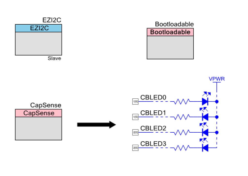
PSoC Analog CoProcessor Schematic
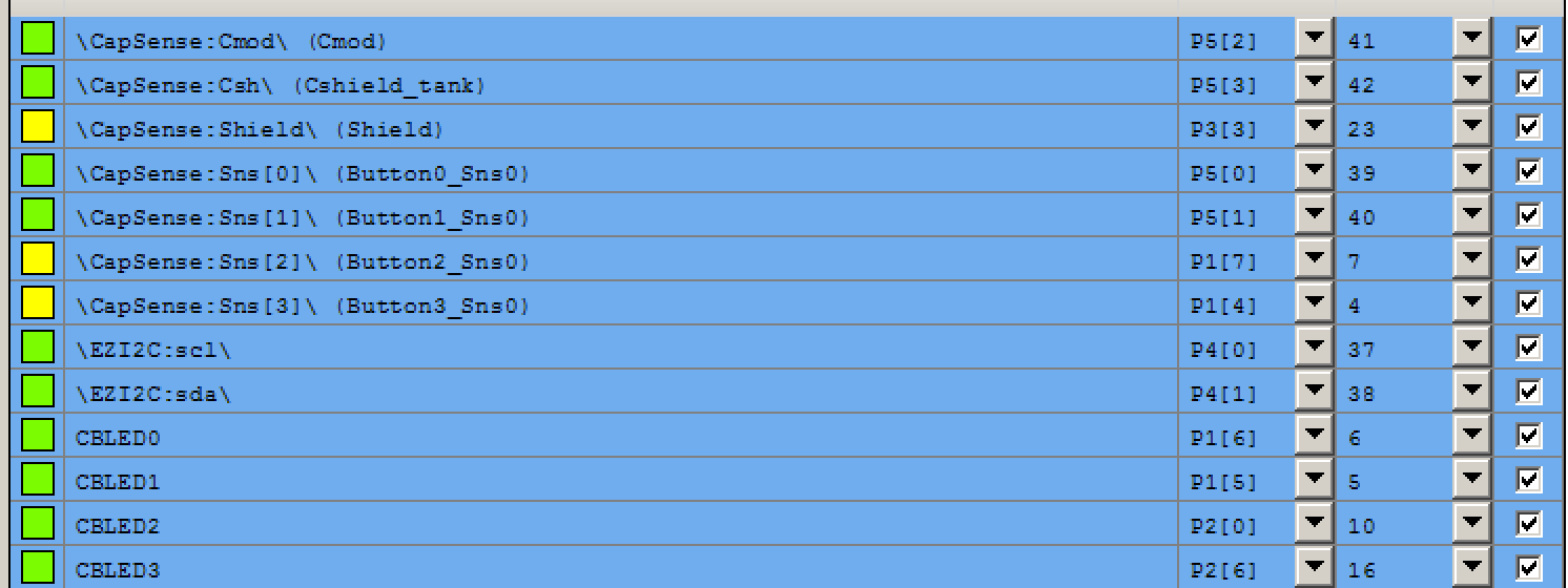
The PSoC Creator schematic is pretty straight forward. I use the EZI2C slave to provide communication for the WICED board. There are 4x LEDs that sit right next to the CapSense buttons, and there are the 4x CapSense buttons. The only slightly odd duck is the Bootloadable component which I use because when I designed the shield I did not put a programmer on it. The BootLoadable allows me to me to load new firmware into the PSoC via the I2C interface. Here is the PSoC Creator Schematic:
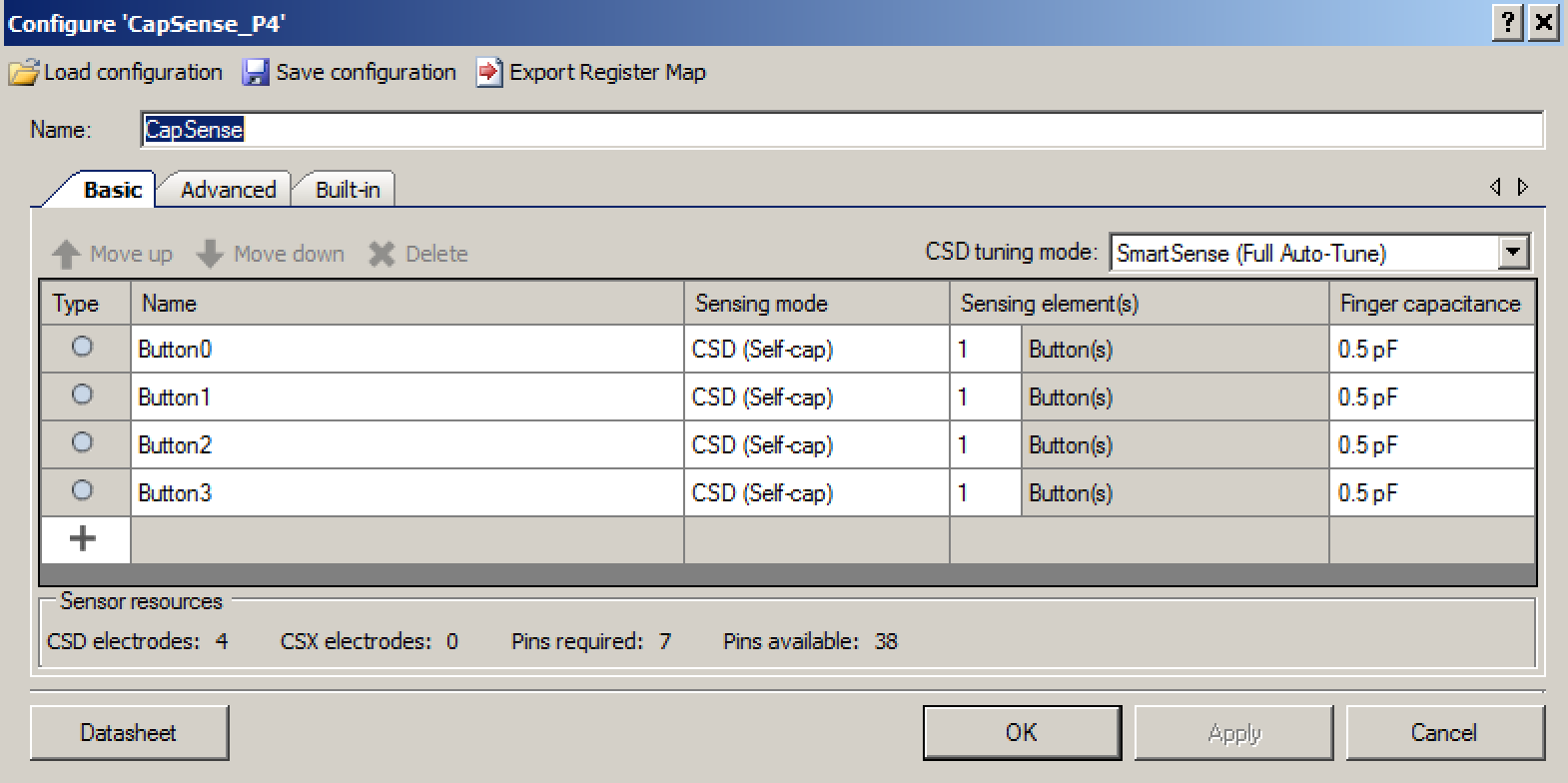
The CapSense configuration just specifies the use of 4x CapSense buttons that are automatically tuned by the Cypress magic.
The last step in configuring the schematic is to assign all of the pins to the correct locations.
PSoC Analog CoProcessor Firmware
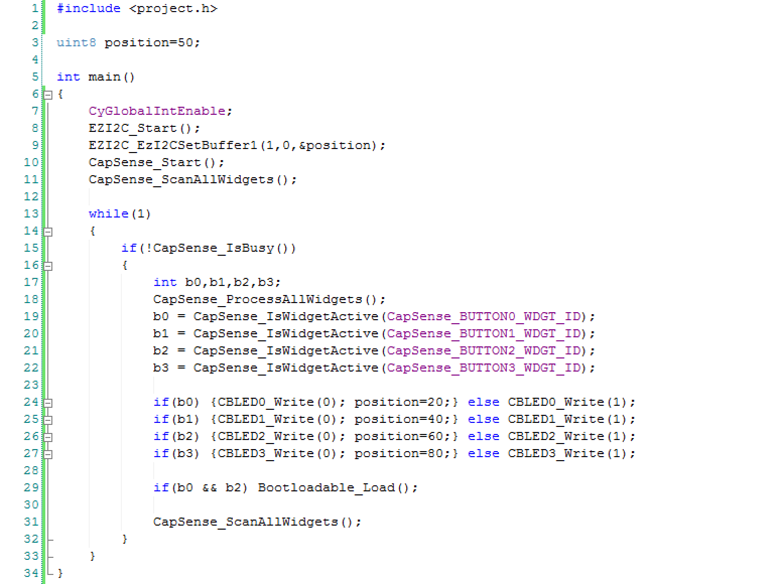
One of the great things about all of this process is how easy the firmware is to write.
Line 3 declares a buffer that will be used to relay the position information to the WICED board. I start the position at 50%
Lines 8-9 start the EZI2C which starts up the EZI2C protocol and tells it to read from the “position” variable
Lines 10-11 gets the CapSense going
Inside of the infinite while(1) loop, I read from the CapSense and do the right thing
Lines 17-22 reads the CapSense status
Lines 24-27 set the correct position based on which buttons are pressed (notice that if no button is pressed then the position stays the same)
Line 29 turns on the Bootloader if B0 & B3 are pressed
Testing the PSoC Analog CoProcessor System
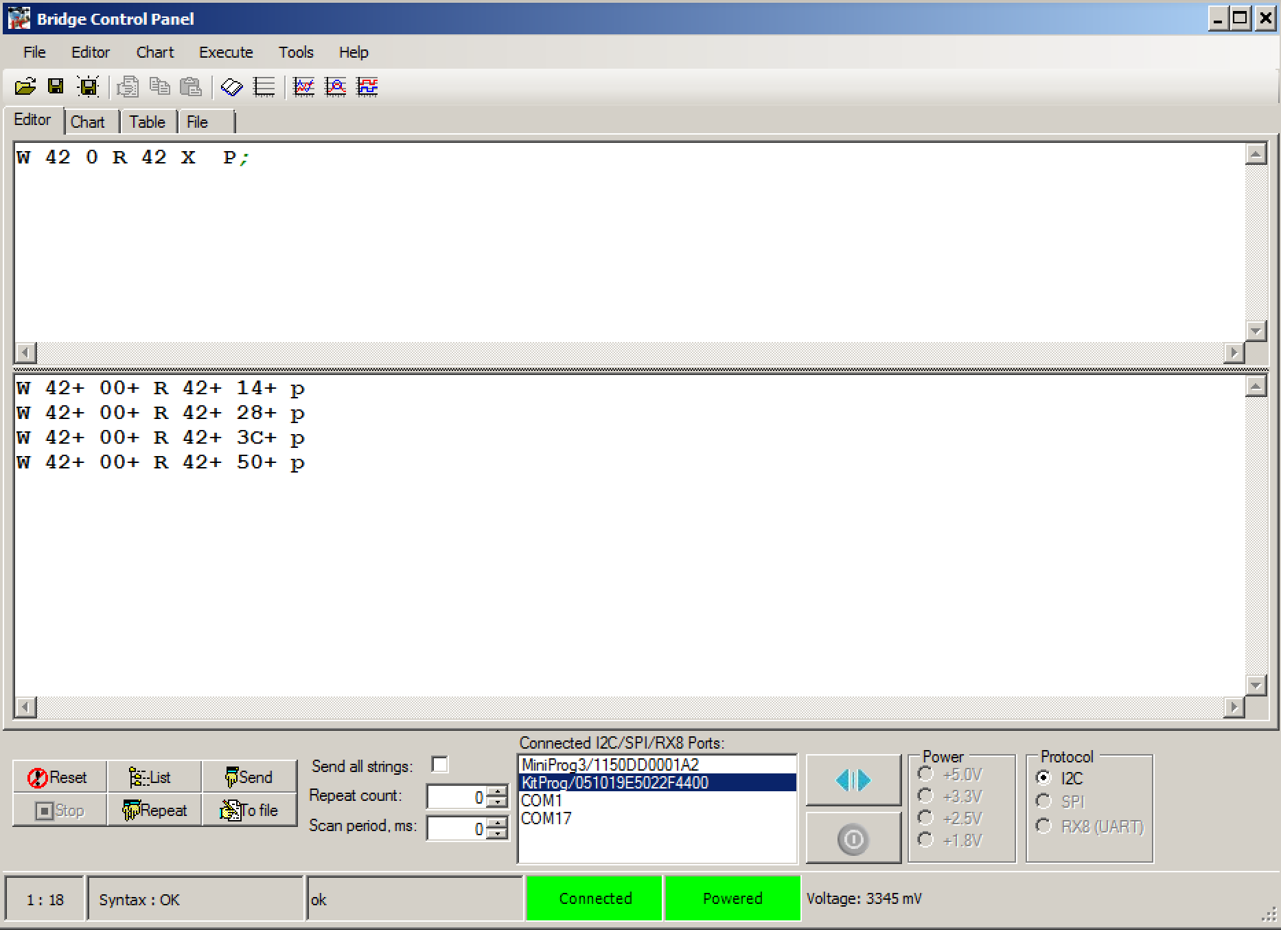
The easiest way to test the system is to use the Bridge Control Panel which comes as part of the PSoC Creator installation. It lets me read the value from the EZ2IC buffer to make sure that the CapSense buttons are doing the right thing. The command language is pretty simple. You can see in the editor window that I typed “W42 0 R 42 X p;” Everytime I press “enter” it sends the I2C commands:
Send an I2C start
write the 7-bit I2C address 0x42
write a 0
send a restart
read from address 0x42
read one byte
send a stop
You can see that I pressed each button and indeed got 20,40,60,80 (assuming you can convert hex to decimal… but trust me)
In the next article I will modify the WICED Publisher to poll the PSoC Analog CoProcessor and then publish the current state.
Pattern Agents are running a crowd funding effort for ThingSoC TSoC4L … help themhere
Summary
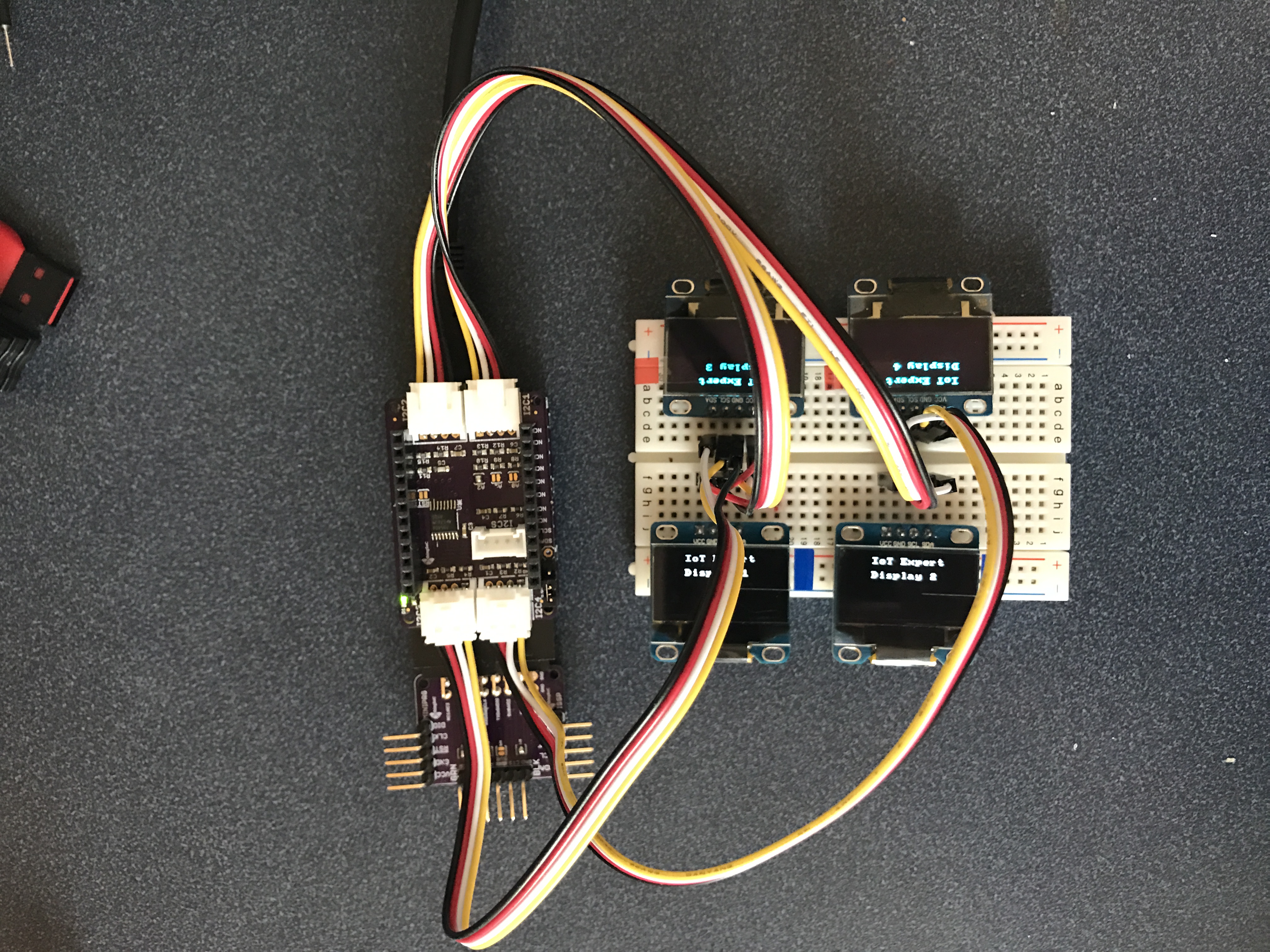
In the previous ThingSoC post I took you through building the firmware to make the PSoC4L drive the ThingSoC I2C hub. Now what? When originally looking around I saw a picture with 4x LCDs connected to the I2C hub, which I thought was cool. In this post Ill show you how to do the same thing with PSoC and the U8G2 library which I talked about in this article. To do this I will:
Create New PSoC4L Project + Integrate the U8G2 Library
Update the PSoC4L Firmware
Test the PSoC4L Firmware
Here is the picture:
Create New PSOC4L Project + Integrate the U8G2 Library
Maybe it should have been obvious, but for some reason it never occurred to me to do a copy/paste to duplicate a project. I guess that I’m slow that way. To do this right click on a project in the workspace explorer and then do paste.
The next step is to integrate the firmware from the U8G2 Library. Start by “gitting” with “git@github.com:olikraus/u8g2.git”. Then you need to add the directory to your project by right clicking the project and selecting “Build Settings”. You need to add U8G2 Library to the additional include directories.
Add the all of the .h and .c files by right clicking the project and selection “Add->Existing Item”
Navigate to the U8G2 library and add all of the .c and .h files. The last thing you need is to bring in the HAL that I wrote for PSoC and described in this post. Specifically you need to bring in the two functions
psoc_gpio_and_delay_cb
u8x8_byte_hw_i2c
I suppose that I should package the whole thing up in a component. But, Ill leave that as an exercise for the reader.
Update the PSoC4L Firmware
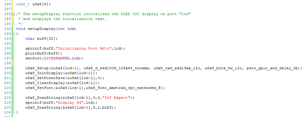
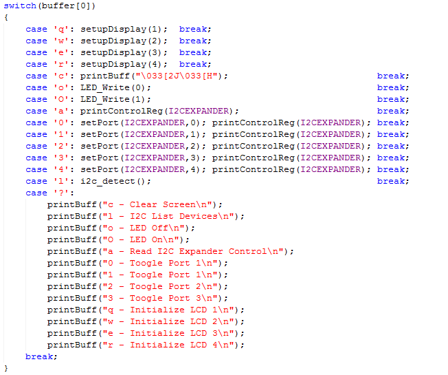
The cool thing about the whole setup with the I2CHUB is that it allows you to have 4 devices with the same I2C address attached to one PSoC SCB at the same time. To get going with the firmware, I start by defining an array of u8x8_t structures to represent the 4 different displays attaches to the 4 different ports on the I2C hub. (line 186). Then I create a function called setupDisplay that initializes the display etc. (lines 199-203). The only trick in the firmware is that Dennis Ritchie defined arrays to run from 0-3 but the I2C busses are labeled 1-4, this is the reason for subtracting 1 from the input lcd number.
The next step is modifying command processors in the main loop. Specifically, I will add the commands q,w,e,r to startup the displays on I2C ports 1,2,3,4. And, I will add those commands to the help print out.
Test the PSoC4L Firmware
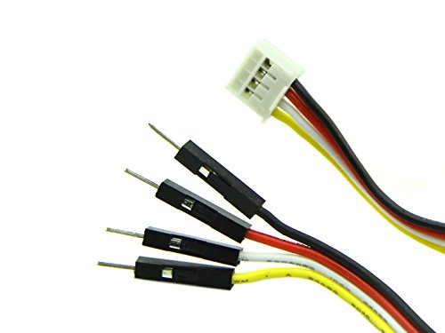
In order to make a connection from the Grove 4-pin connectors to my breadboard I used Switch Doc Labs connectors which I bought from Amazon.com. For some reason you can’t purchase them from the Switch Doc Labs website or the SeeedStudio website, but they are very handy. As an unrelated side note I had never seen (or in fact ever heard of) Switch Doc Labs. But their website has a bunch of tutorials about the Raspberry Pi and Grove ecosystem boards for use with IoT-ifying house plants. Seemed pretty cool.
Now when I press “qwer” in my command console I get this:
You can find all of the projects in the TSoC Series at my GitHub ThingSoC repository git@github.com:iotexpert/ThingSoC.git
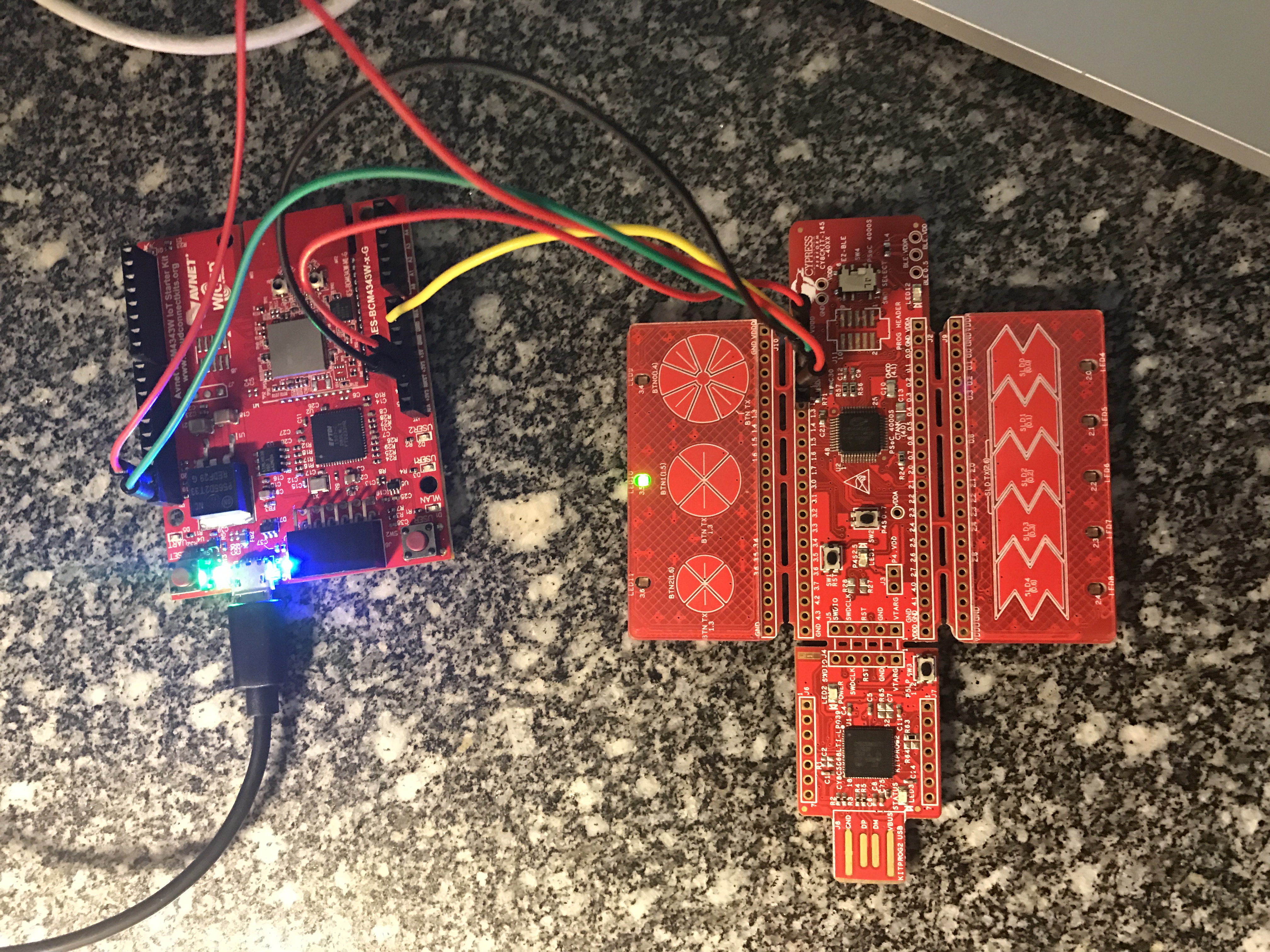
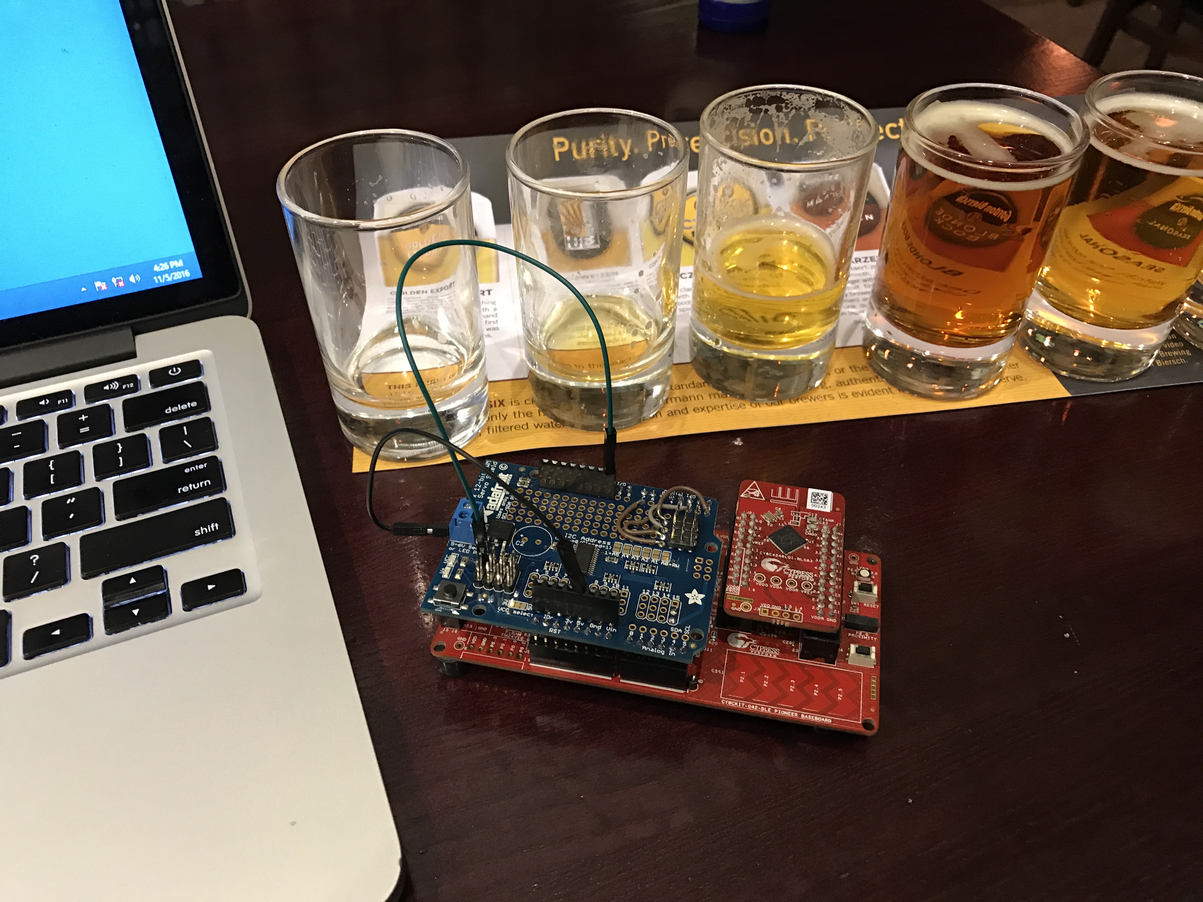
I finally made it to Munich late yesterday afternoon… then I proceeded to turn my hotel room into an electronics lab as I frantically worked to finish everything for tomorrow. Earlier this year I wrote a whole series of posts about the PSoC4000S & CY8CKIT-145 after the Embedded World show. We finally have volume production on the development kit and will be giving them out at the show this week. So, I decided to use the -145 as part of the user interface for my Electronica project. The devkit functions as the block labeled “PSoC Capsense”. The wire between the “PSoC Capsense” and the “WICED WiFi” will be I2C (the green and red wire from the picture below)
The -145 devkit has the PSoC4000S silicon on it which has the new mutual capacitance capsense block. On the devkit, there are three mutual cap buttons and one slider. Here is a picture of the devkit connected to the WICED WiFi board that I am going to use:
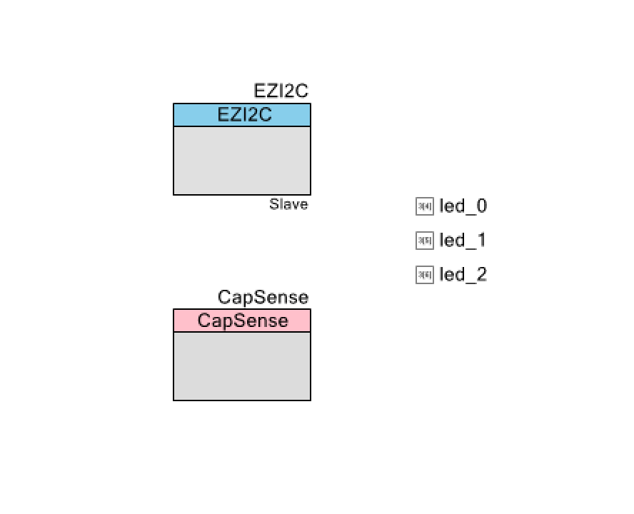
I want to make as simple of a PSoC Creator project as I can possibly do as I want to be able to easily do it live. Here it is:
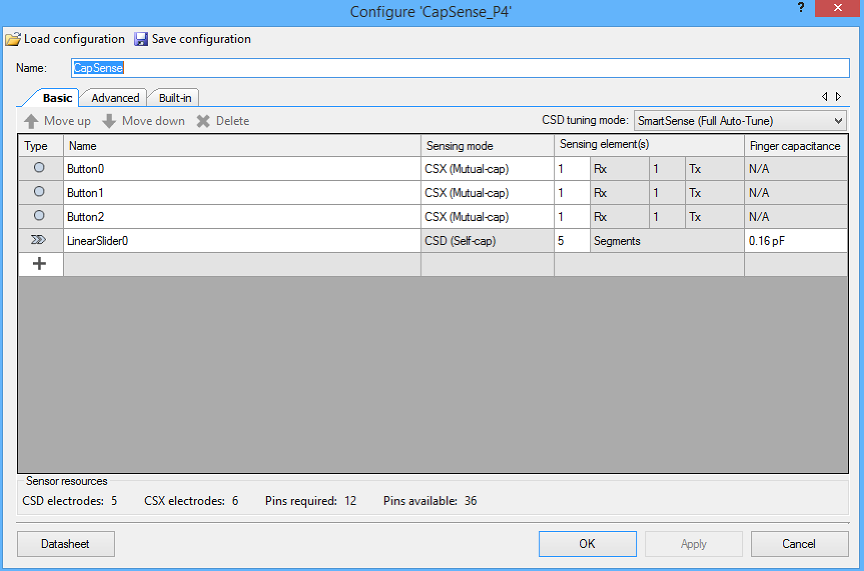
The CapSense block is configured with three mutual cap buttons and 1 self-cap slider:
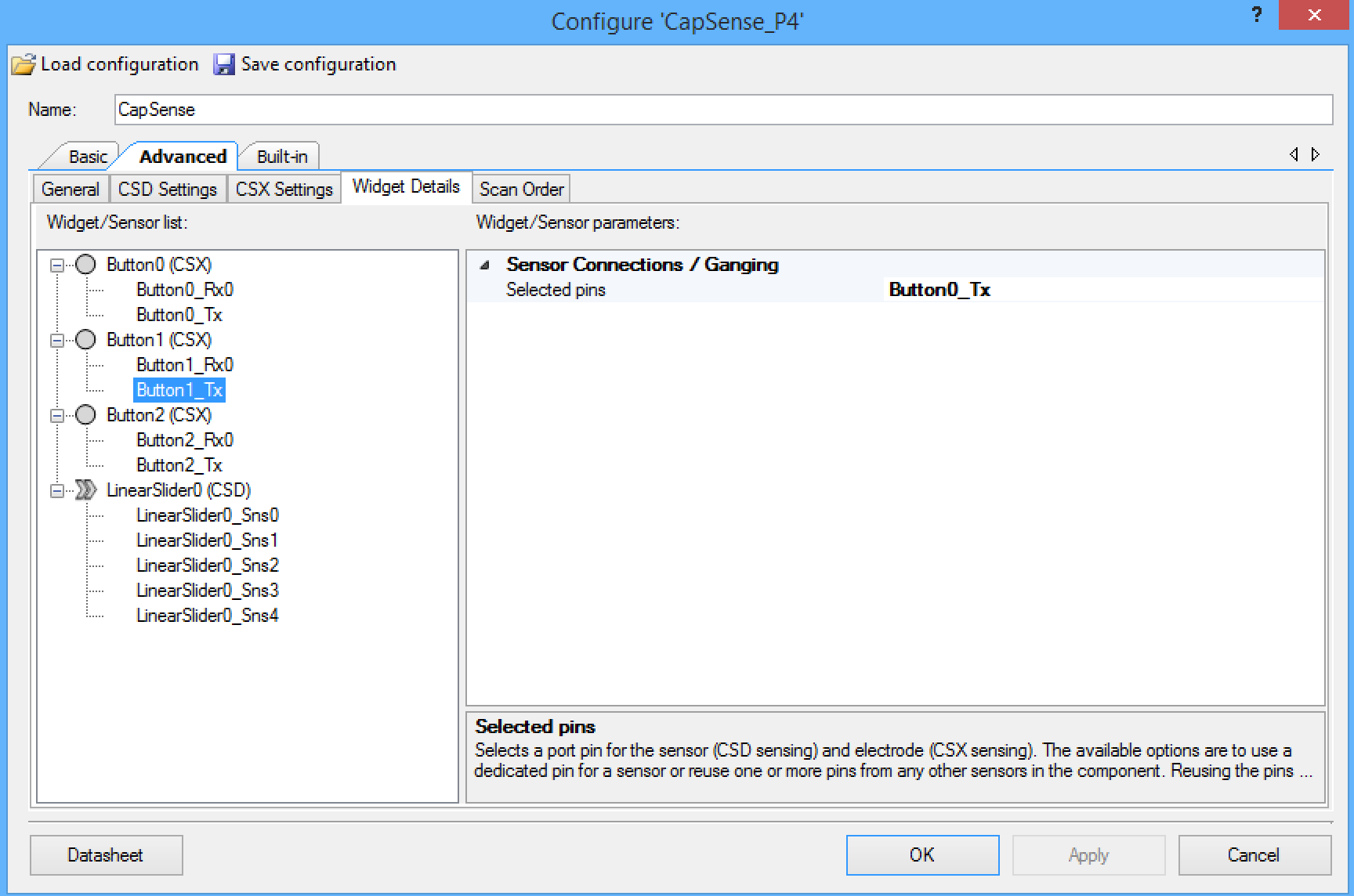
On this development board, the three mutual cap buttons share the same transmit line, so you need to configure the component that way. The screen shot below shows the configuration of the “Button1_Tx” which is set to share the “Button0_Tx”. You need to make the same setting for “Button2_Tx”.
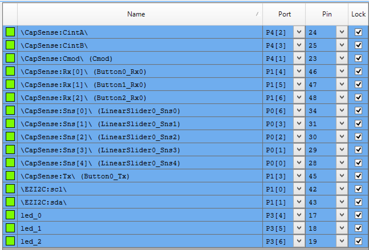
The next step is to assign all of the pins to the proper locations:
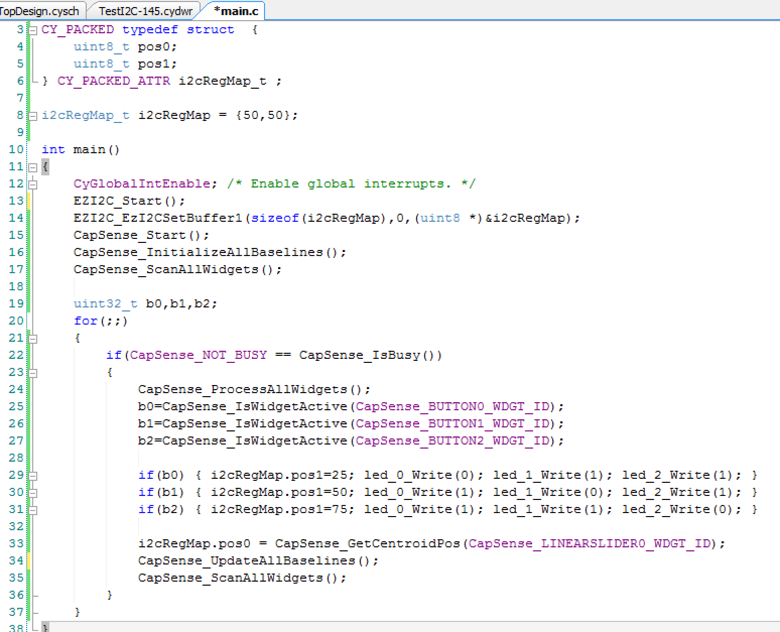
Finally the smallest amount of firmware that I could think up to hold it all together.
Line 3-6: define a structure that the WICED board will be able to read. It will represent the position of two of the Servo motors. The CY_PACKED provides the compiler appropriate key words to make the bytes be right next to each other in the RAM, i.e. not word aligned..
Line 8: initializes both positions to 50%.
Lines 12-17 get the components going
Line 22: Checks to make sure that the CapSense block is not scanning before it reads the results
Line 24: Tells the CapSense block to process the results from the previous scan
Lines 25-31: Looks at the three buttons, sets the LEDs and sets pos1 to be either 25%, 50% or 75%
Line 33: Reads the position of the slider and assigns it to “pos0”
Lines 34-35: Gets the scanning going again
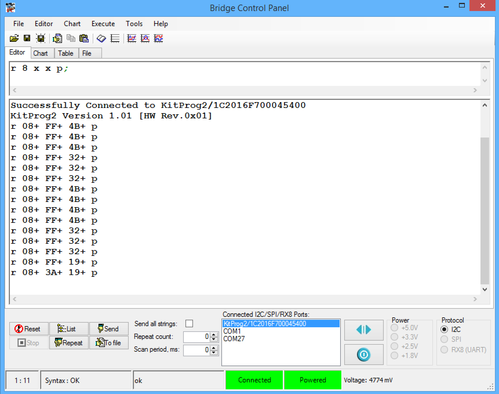
To test the system I first used the bridge control panel. First, connect to the kitprog2. Then I setup a read from the I2C address (0x08) which is the address of my board. I then click repeat which runs the read command over and over again. In the picture below you can see that I tested the three position of the button (25,50 and 75 which are also known as 0x19, 0x32 and 0x4B). Then I tested the slider by touching it about in the middle (0x3A)
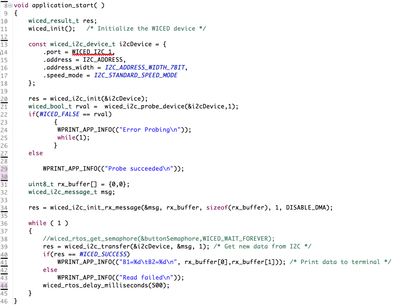
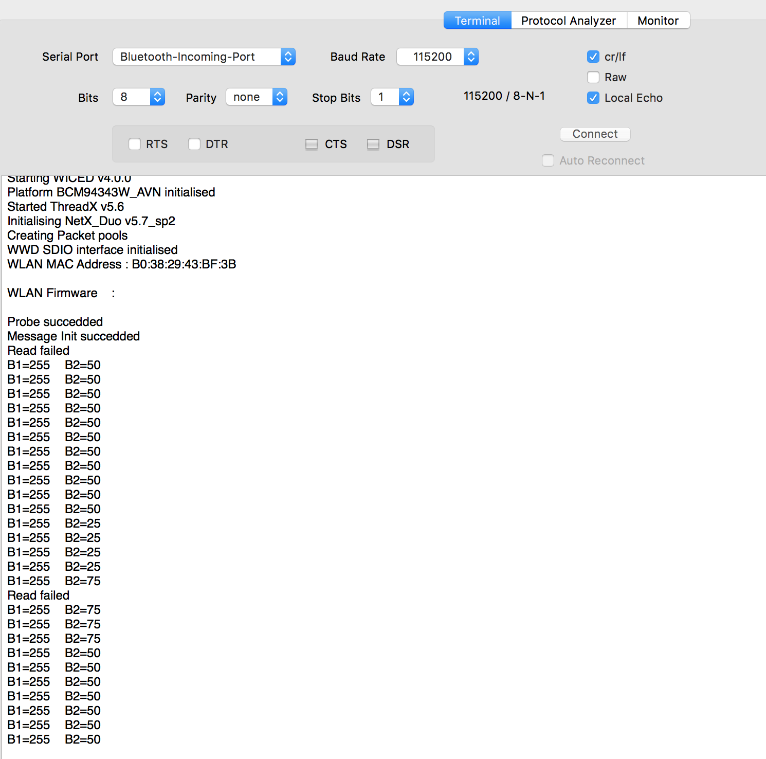
The next thing to do was make sure that the WICED devkit could read my I2C slave, so I wrote some WICED firmware to read the I2C registers every 500ms:
But, occasionally I was getting a “read failed”:
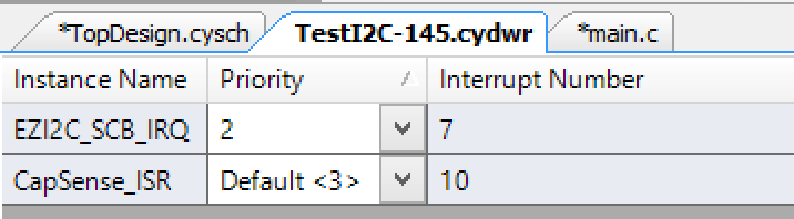
Last night in my sleep deprived state I was struggling like crazy to figure it out. This morning after some sleep I realized that the WICED board that I have must not like getting its I2C clock stretched. So, I changed the priority of the I2C interrupt on the PSoC and that fixed the problem:
Keep watching here for more updates on the project.
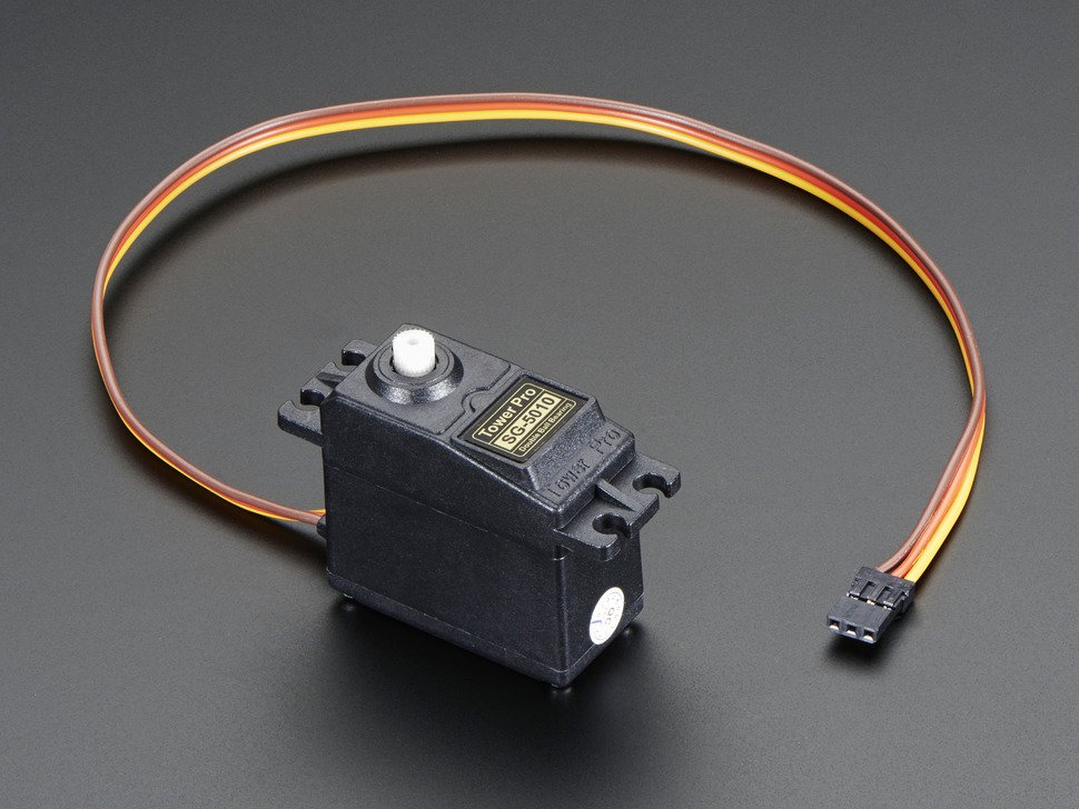
As I talked about in my previous post I am going to use a PSoC as a servo motor controller as well as a CapSense UI. The problem is that I wanted a really easy way to plug the servo motors into the PSoC. It seems like all of the servos have a 3 wire interface, Power, Ground and PWM. Here is a picture that I got from Adafruit’s website.
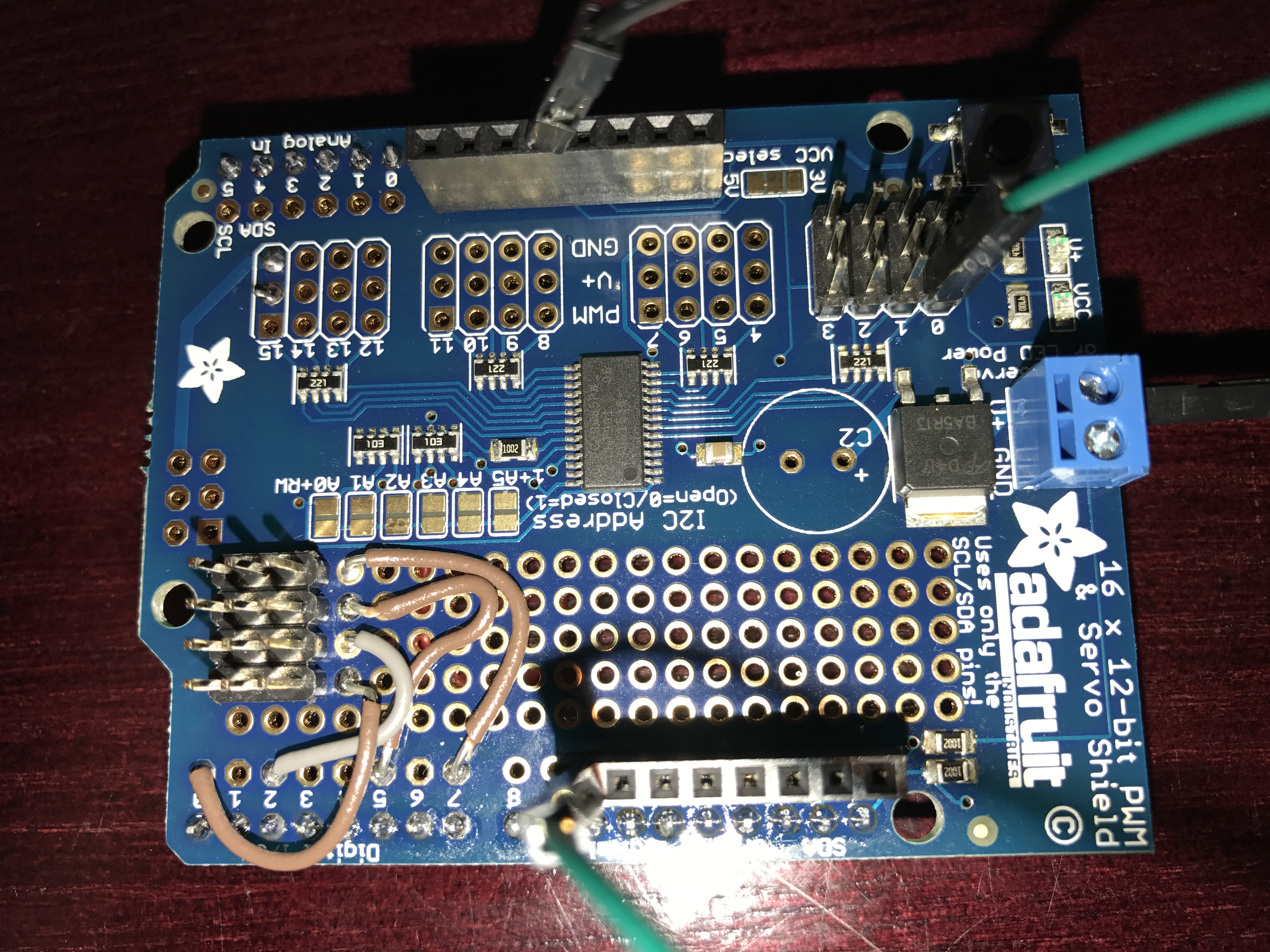
I was originally hoping that I could connect that servo directly to the PSoC, drive a ‘1’ to the power and a ‘0’ to the ground and PWM to the third input. But, it turns out that these things suck some serious juice (100+ma?) so driving the power with the PSoC isn’t in the cards. Given them amount of time that I had left, there was not time for a custom board, so I was in the situation of using a breadboard with wires all over the place which is ugly and a bit of a pain. However, on Thursday I thought that I might find a “Servo Shield” and sure enough there are a number of them out there including this one which I got from Adafruit. The problem is this shield uses a 16 channel I2C –> PWM driver from NXP. I am not a fan of doing things with peripheral chips that PSoC can do for itself. But, when I got the shield this morning in the mail there was a cool prototyping area on the shield. So, I made my own header for connecting to the PSoC. Here is the front:
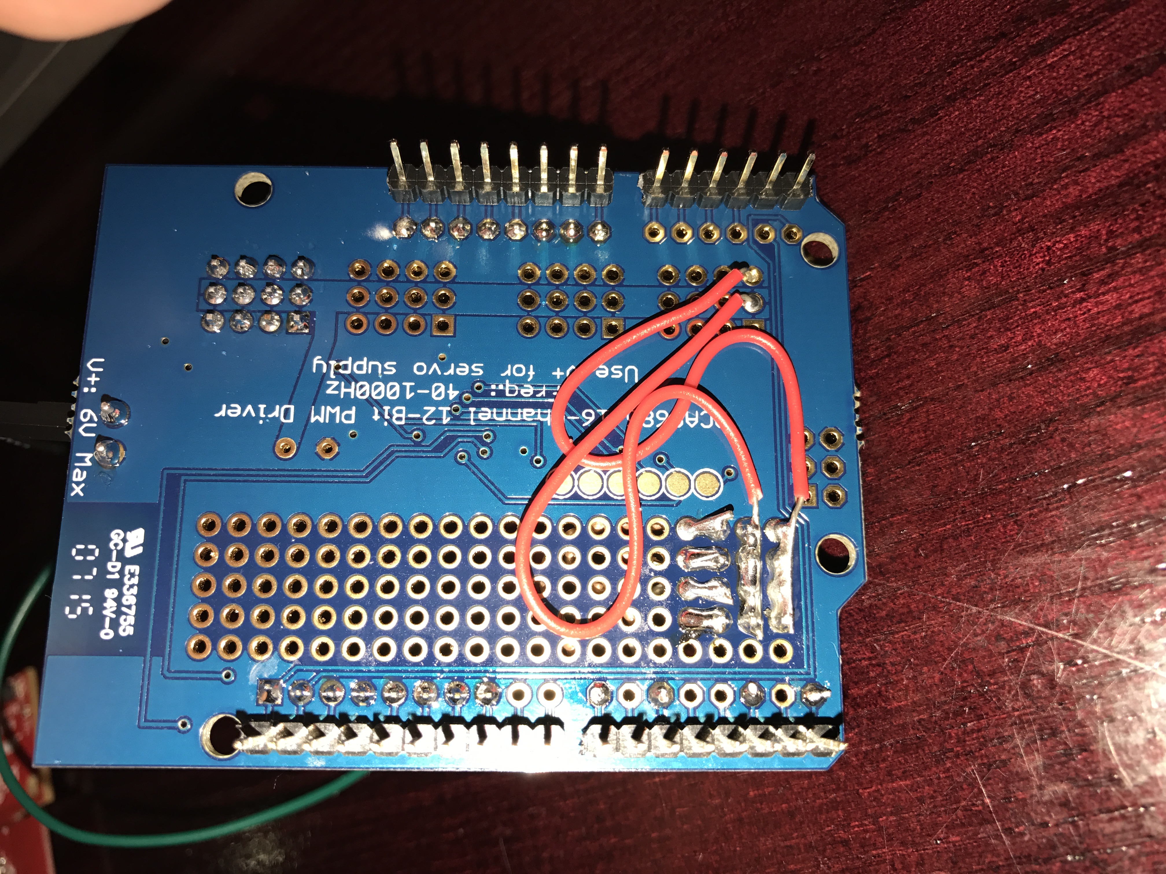
And here is the back:
You can see that I shorted the whole row of ground together with a big blog of solder and wire. I did the same thing with the power (the middle row). Then I made a wire from each of the 4 PWMs pins to a good place on the PSoC (which I could drive the pins directly from one of the TCPWMs)
The board worked great on my bench. The only thing that I have done which is VERY questionable is that I wired the power supply for the system directly to the V5.0 aka VBUS… which I suppose will get me through the conference, but is probably a bad idea (the green wire in the top picture)
As I was flying to Detroit I thought that I might try to see how the I2C->PWM worked… so I read the data sheet for the NXP PCA9685. It turns out that the chip is pretty cool. You can set the output frequency by setting a divider value in one of the registers (oxFE). The number you set is val=round(25e6/(4096*rate)) – 1. That means for me to get 50hz to drive the motors I need to set the divider to 121. Then to set the duty cycle each output has a 12-bit PWM where you can set “LED ON” and a “LED Off” count. For instance to get a 25% duty cycle you can set the On to 0 and the off to 1024.
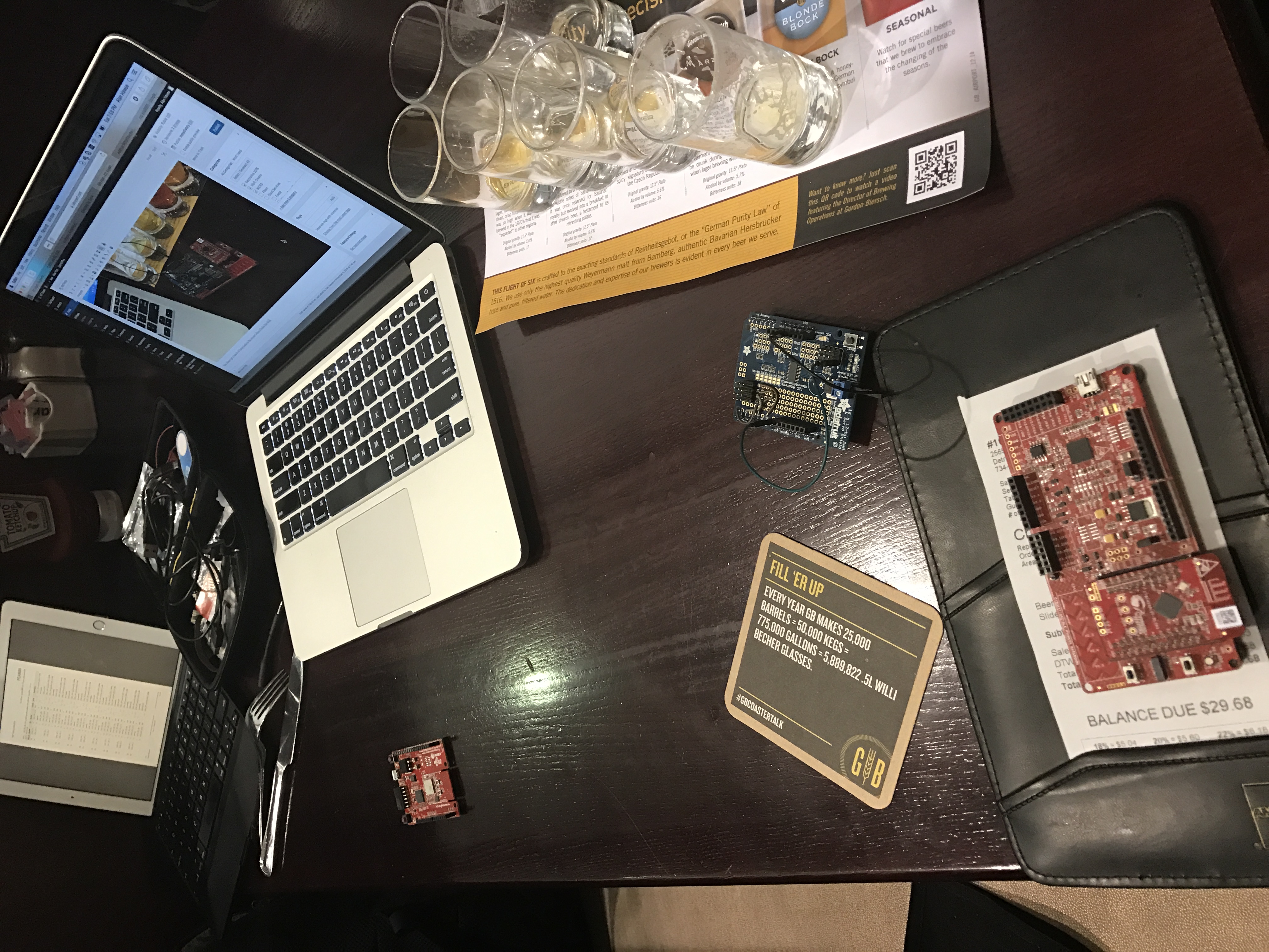
After I got off the airplane in Detroit I went to get some “dinner” and I wanted to try out the shield so I hooked it up:
You always get a bunch of funny looks in the airport when your table looks like this:
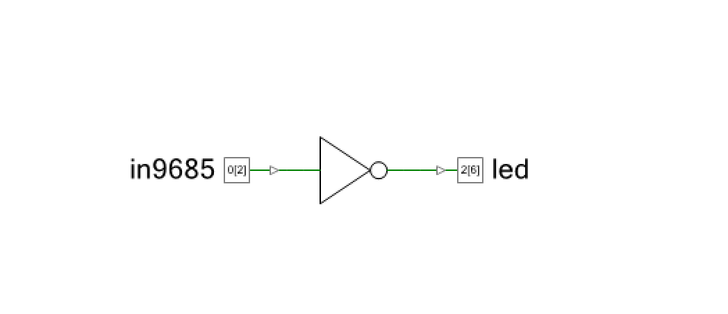
This left me with only one problem. How to drive the shield PWMs onto something that I could see… I didnt pack my Tek in my carry on (though I suppose I could have used one of those little scopes). But, I digress. What I decided to do is make the PSoC echo an input onto on output pin that was connected to an LED. So, I drew this schematic. This can only be done in with a PSoC because I used a logic gate in the UDB to flip the 9685 PWM from Low to High so that my active low LED would work right.
Next I fly to Charles De Gaul, the suckiest airport in the first world. What will I do on the airplane there? I don’t, but given those empty beer glasses I may sleep. More to follow when I get to Germany.
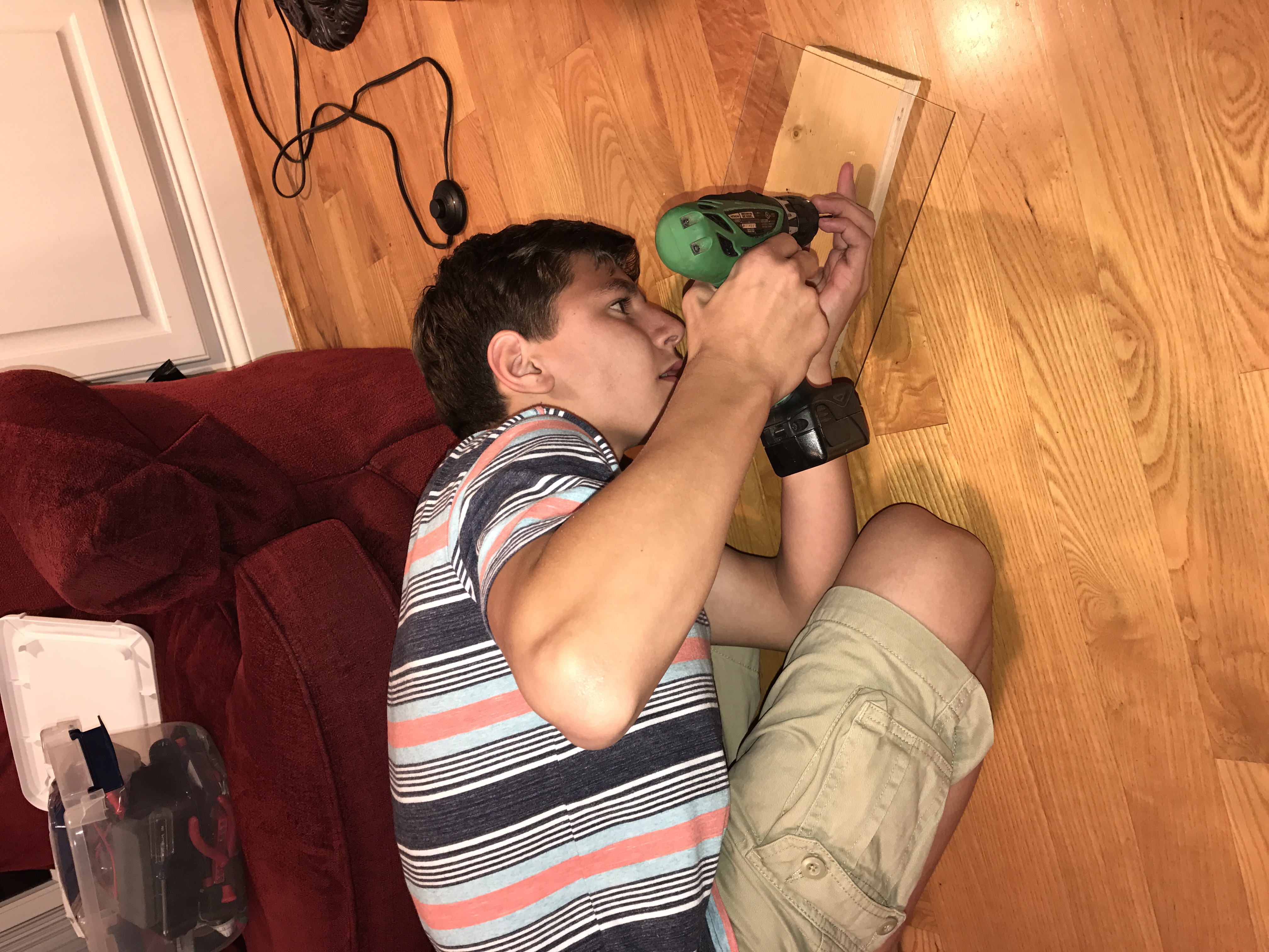
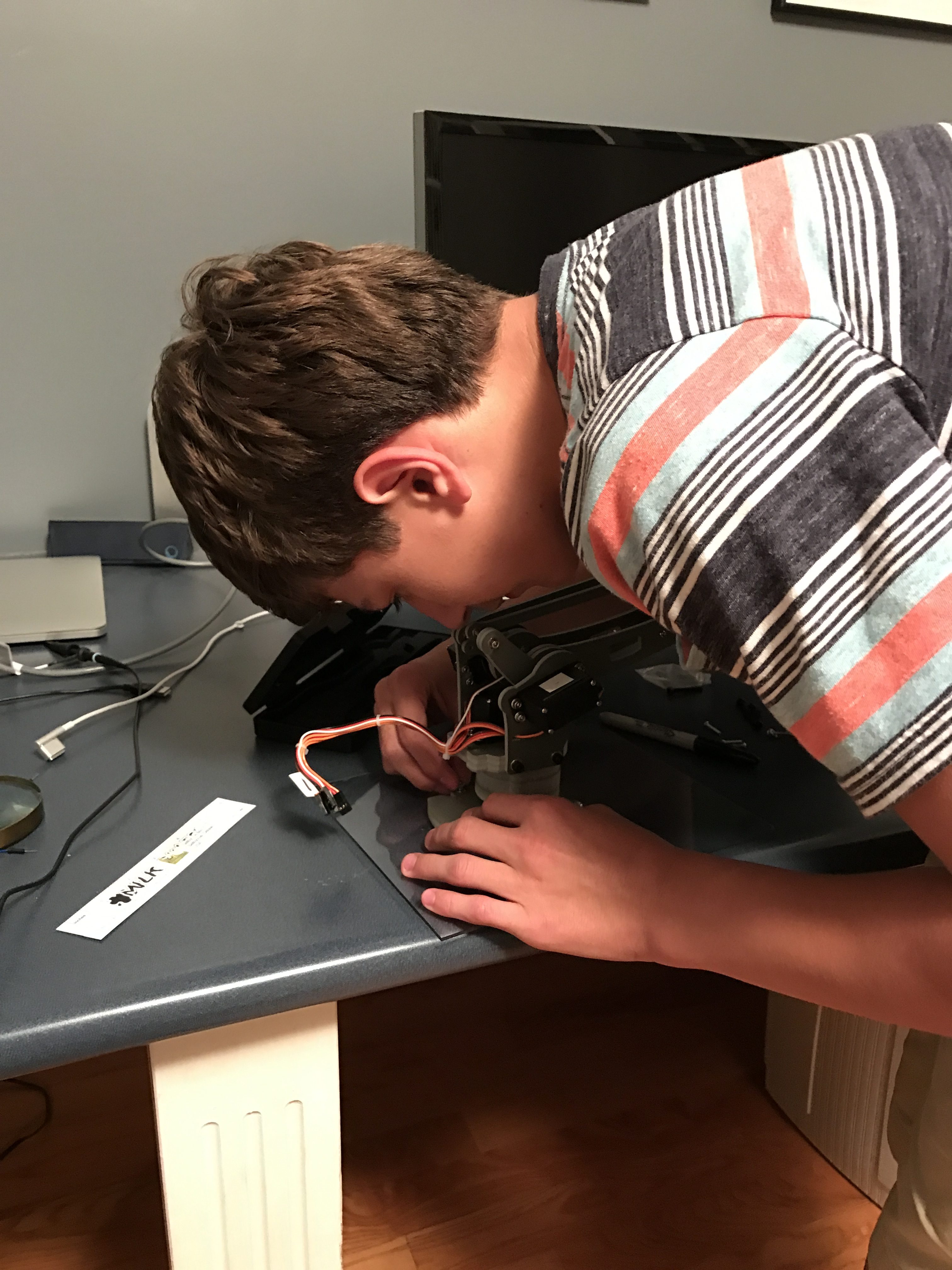
The good news is that the Robot Arm arrived from Amazon, which I was very happy about because it was a day late. The even better news is that it works like a charm. First I needed to assemble it, which I did with a little bit of help from my able lab technician and a trip to Lowe’s to get a base.
Then “we” attached the base to the Robot.
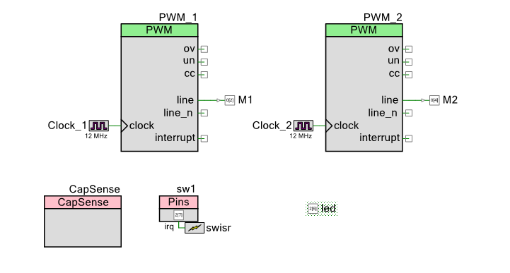
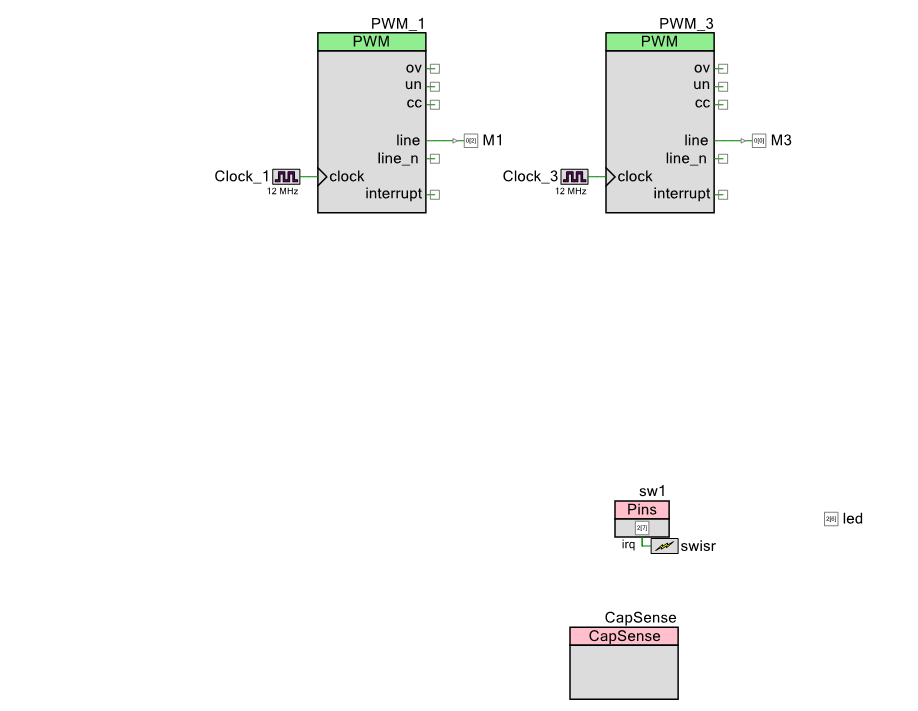
After the robot arm was put together on the base, I needed a little bit of firmware to run it. First the schematic: You can see that I have
Two PWMs – one for each Servo motor
A Capsense slider to move one of the axis on the robot
A switch and LED to turn On/Off the PWMs
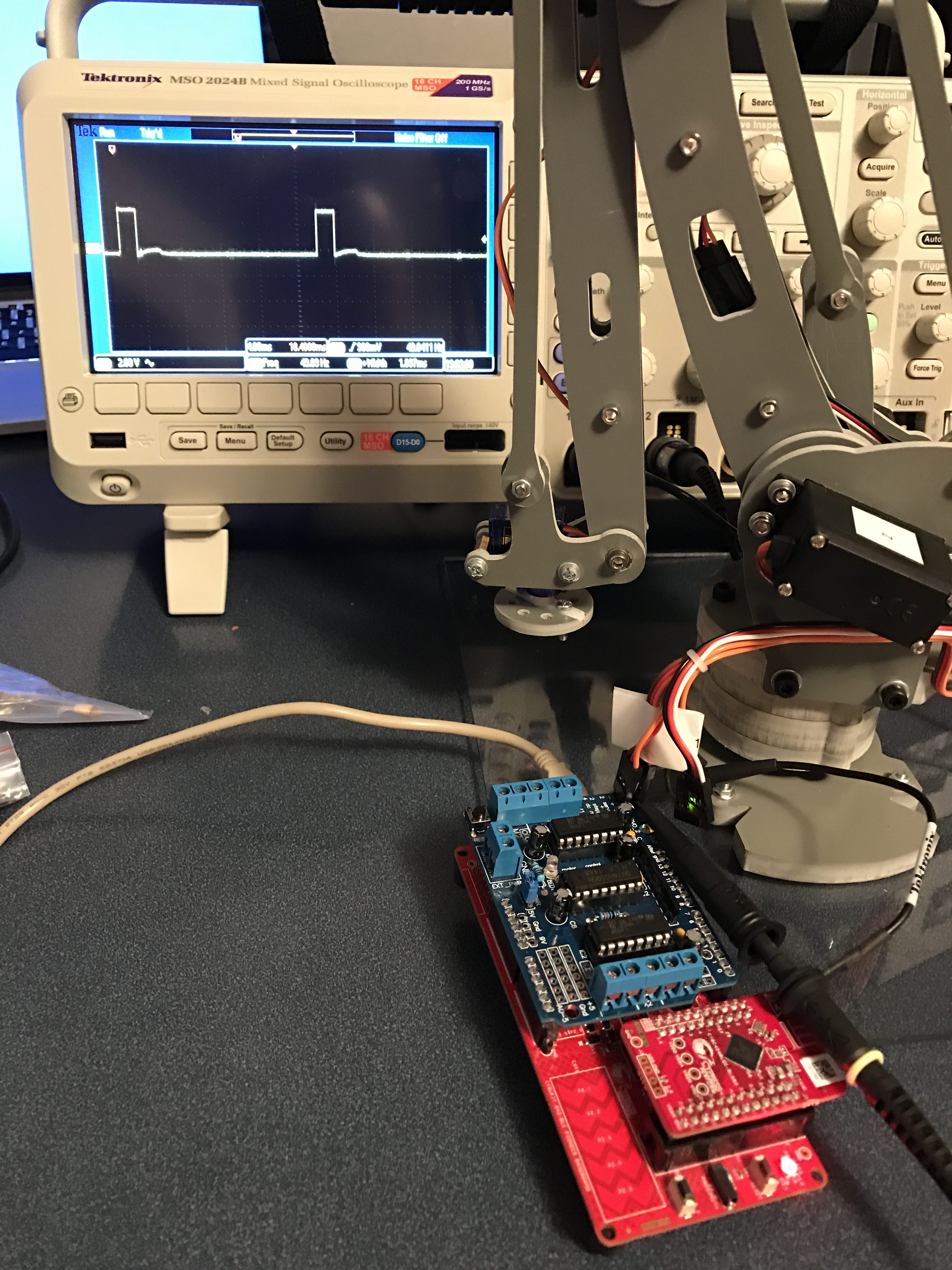
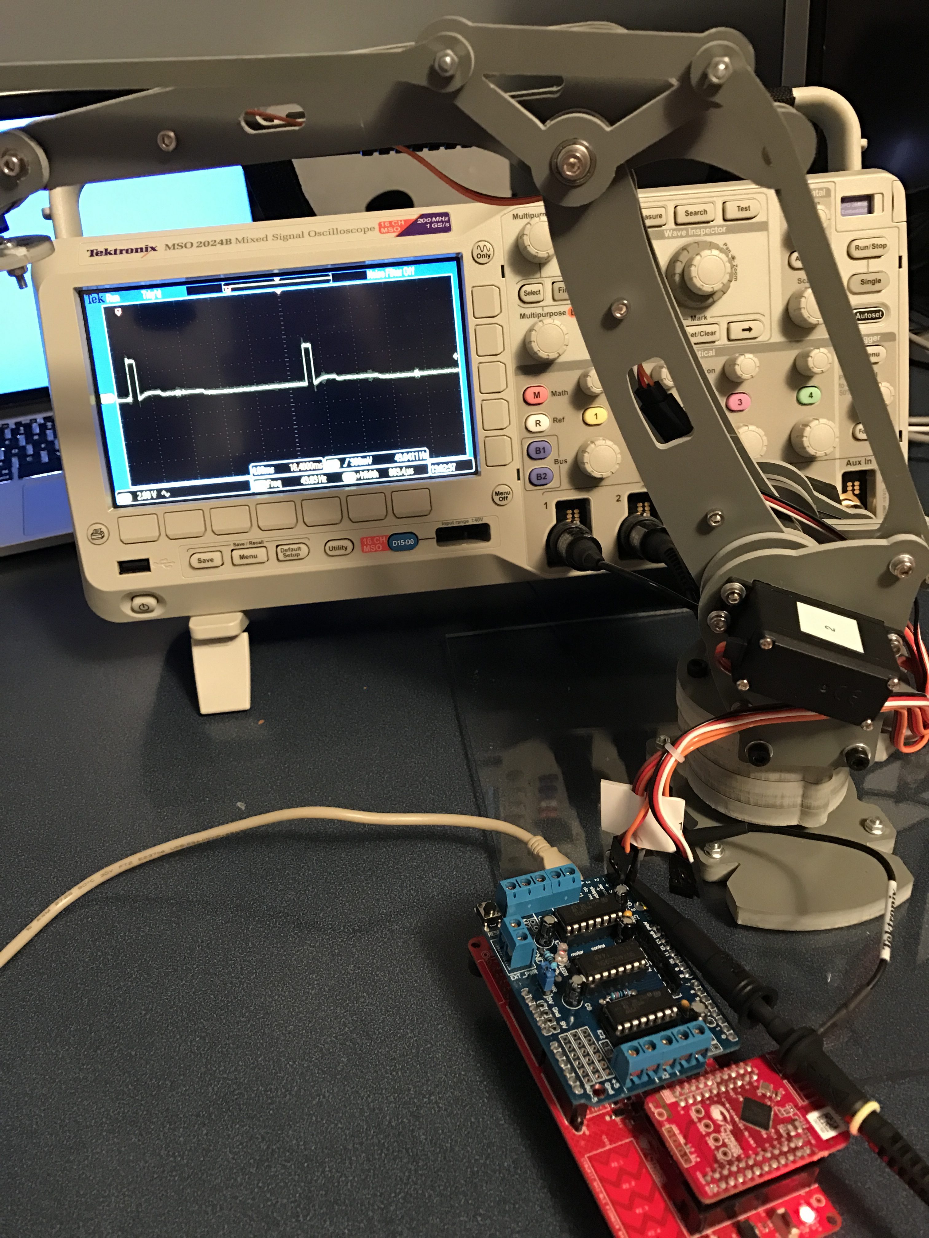
The robot arm has 4 “axis” which are each controlled by “servo” motors. Servo motors have a small controller built into them that takes an input signal that is created by a PWM and turns the motor to the right place. To drive the motor you need a input signal that is 50HZ, with a high pulse that ranges from ABOUT 1ms to 2ms. When the pulse is 1ms the motor is all the way one direction, when the pulse is 2ms it is all the way the other direction. To make the motor do what you want you give it a pulse somewhere in the middle, for instance if you want it to be half way then the pulse width is 1.5ms.
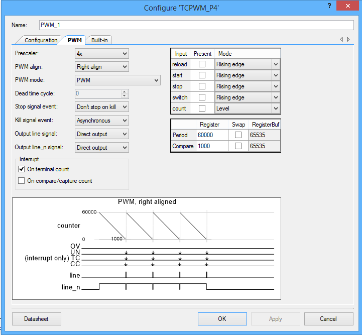
The easiest way to make this work is with a Pulse Width Modulator (PWM). Conveniently enough, the PSoC4 BLE that I am using to build this project has 4 of them. I set the input clock on the PWM to 12MHz, then I turned on the prescaler to divide by 4. I then set the period to 60000. Given all of that, the output frequency is 50hz. which you can calculate by 12,000,000 / 4 / 60,000 = 50. Given the period is 50HZ and there are 60000 clock ticks per period, each tick is 3us. To make things easier on the rest of the system I want to give the input a range between 0% and 100% (as an Integer). This lets me calculate the number of ticks I need to set the pulse width. The formula is 3*(1000 + 10*percent). I determined this empirically with an oscilloscope and changing the values to see the range of motion of the Robot Arm.
To achieve all of this, the PWM configuration is:
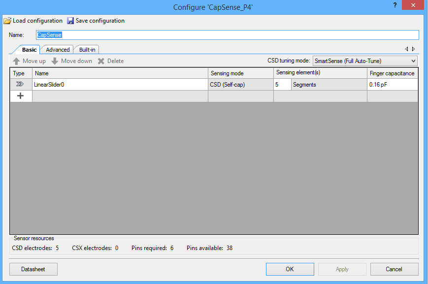
Now I configure the CapSense block to have a linear slider.
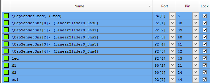
Finally I assign the pins:
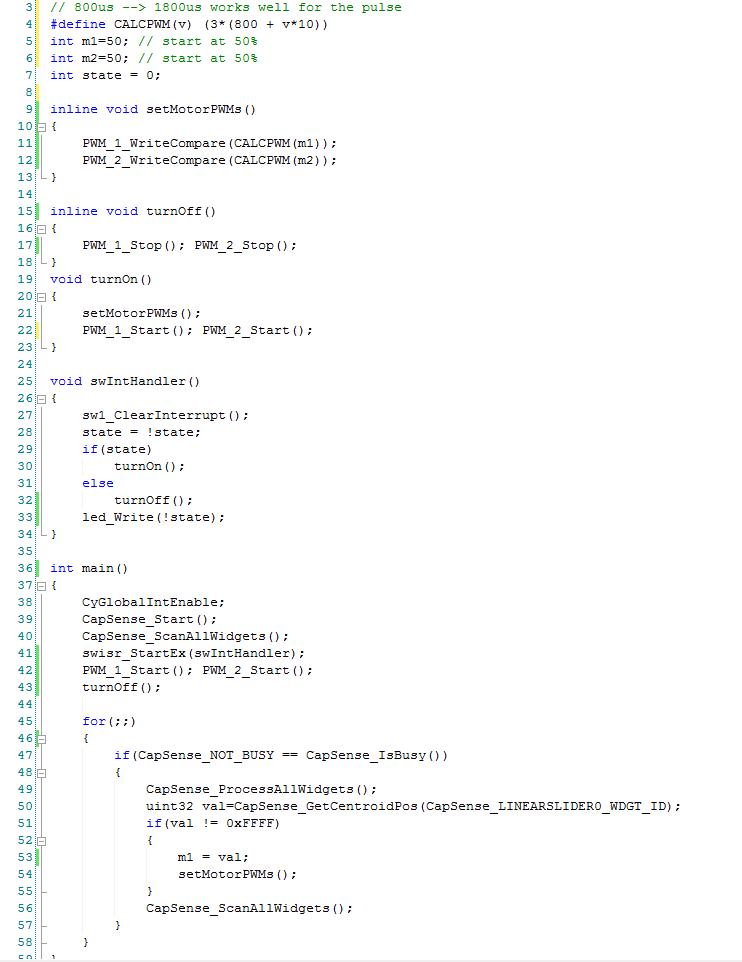
And a little bit of firmware:
Line 4 is a #define macro that calculate the correct compare value for the PWM. After a little bit of experimenting with the Robot I figured out that it really wants the PWM to range between 800 microseconds and 1.8 milliseconds.
Line 5-7 initialize the original position of the PWM
Line 15-19 and 19-23 are helper functions which just turn on and off the PWMs.
Line 25-34 is an interrupt handler that is trigger when the user presses the switch. It toggles a global state variable, turns on or off the PWMs and turns on/off the led.
In main I get things going on lines 38-43. Then start an infinite loop that reads the capsense, and if the value is set then I set the value for the PWMs. Remember that the capsense slider returns a value 0-100 so I can use it directly.
After all of that my lab technician once again test it:
In the previous posts I described the main application firmware and the bootloader firmware. In this post I will take you through the process of verifying that it all works. In order to do this I need to:
Test the bootloader (verify that I can bootload)
Test the main application firmware (the subject of the next post)
Verify the pressure sensor
Verify the temperature sensor
Verify the I2C communication
Testing Bootloader
Cypress makes a cool programming tool called the MiniProg-3 which we also call CY8CKIT-002. The MP3 is a multi purpose tool that can be use to:
Program and debug Cypress PSoC chips
Bridge USB <-> I2C (which I will use to test the firmware)
Bridge USB <-> JTAG
Bridge USB <-> ISSP
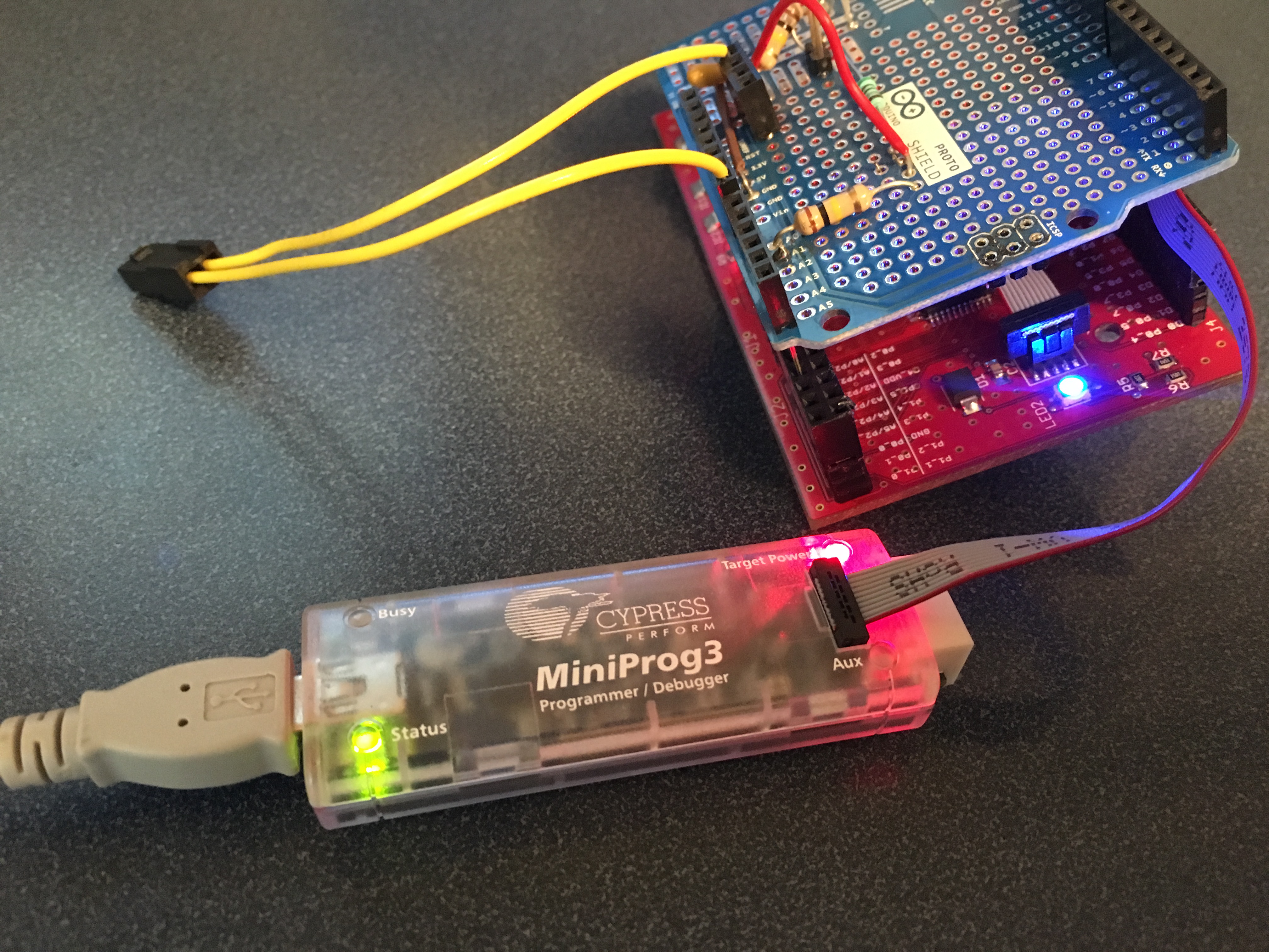
First, I will program the bootloader firmware using PSoC Creator connected via USB to a MP3. In the photograph below you can see:
Mini Prog 3
The CYPI Bridge Board with the PSoC 4
The 10-pin ARM programming header (which is attached to the grey cable from the MP3)
The blue blinking LED. (after I programmed the board the LED started blinking. In this picture I caught it on)
At this point it appears that the bootloader is programmed into PSoC4 as the LED is blinking. In this case I only programmed the bootloader, so there is no application firmware to jump to, so the chip will just keep running the bootloader until the power goes off.
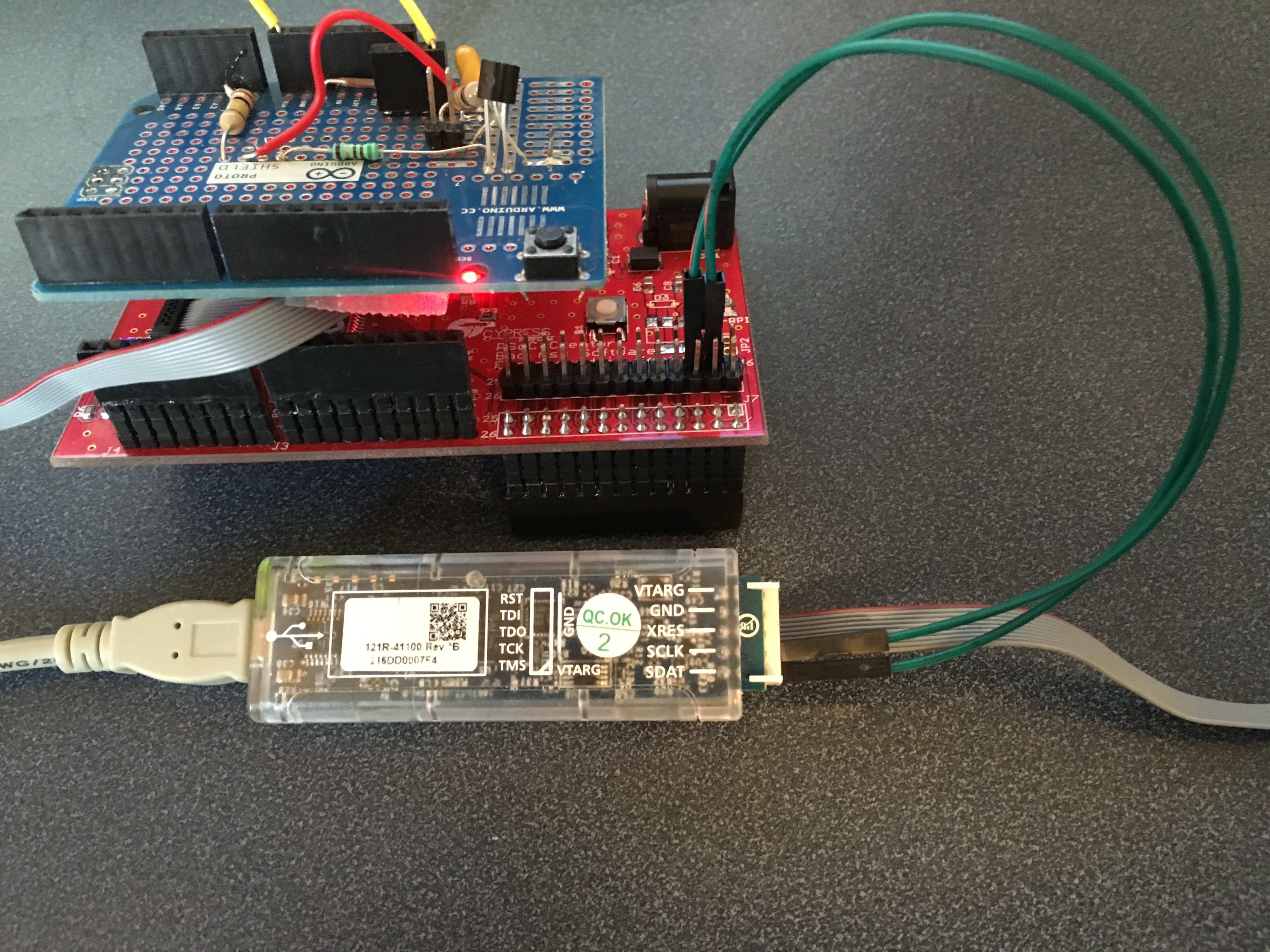
Next, I need to attach another MP3 acting in the role of a USB <–> I2C bridge. The MP3 will emulate the Raspberry Pi which will be used in the production system, but for now it is easier to test without the added complexity of the RPi. I am using one MP3 just as a power source for the CYPI board (I could have just plugged in a wall wart). You can see that I have two wires, one for SDA and one for SCL connected to the correct RPi/CYPI pin. The other side of the wires are sticking into the correct female connectors on the header of the MP3 (right next to each other at the bottom).
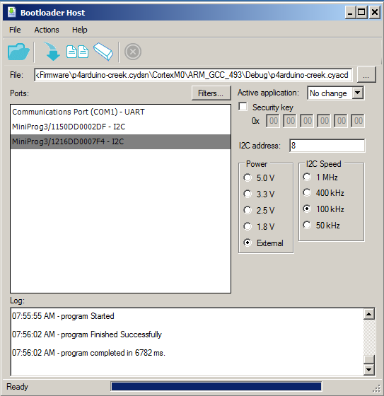
Then I start the bootloader host which is a program that can read CYACD files (which is just a format of a hex file) and send it out over I2C (or UART) using the bootloading protocol. First, I select the correct CYACD file from the directory where PSoC Creator put it. Then I click the download button.
A few seconds after the boot loading is finished, the blinking blue led turns off and a blinking red led starts. This indicates that the main application firmware is running. To verify that the bootloader still works I press the reset switch on the board and the blue led starts blinking for 10 seconds before jumping back into the application firmware. Good. The bootloader and application firmware work together correctly.
In the next post I will show you how to use the Bridge Control Panel to verify that the firmware is working correctly.
In the previous post I discussed the process that I used to test the bootloader firmware. In this post I will walk you through testing the actual application firmware. As I started working on this post I decided to remind myself of the format of the EZI2C buffer. Here it is:
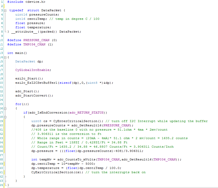
The first thing that I immediately noticed was that I did something really dumb. Specifically I named one of the fields “float pressure” when it is really “float inches”. Oh well. The DataPacket structure is composed of 4 variables, two of them are 2-byte unsigned integers and two of them are 4-byte float. As this PSoC is an ARM chip, all of the variables are stored in little endian format-meaning that the Most Significant Byte (MSB) is last.
To help test the firmware, I will use a program called the Bridge Control Panel (BCP). The BCP is delivered as part of the PSoC Creator installation and is available under the Start->All Programs->Cypress menu. The BCP can talk to a Miniprog 3 (or any of the Cypress programmers) via the USB port and then bridge to the I2C bus. It can then act as an I2C master- in my case it will be emulating the Raspberry Pi I2C Master.
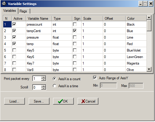
After starting the BCP, I first configure the “chart->variable settings”. This allows me to setup names and sizes of the EZI2C registers that I want to read from the PSoC. You can see that I added one variable to correspond to each variable in the DataPacket structure. In the BCP, an “int” is the same as an ARM int16 aka a two byte integer. I also select “sign” to indicate that the tempCenti is int16 (not uint16).
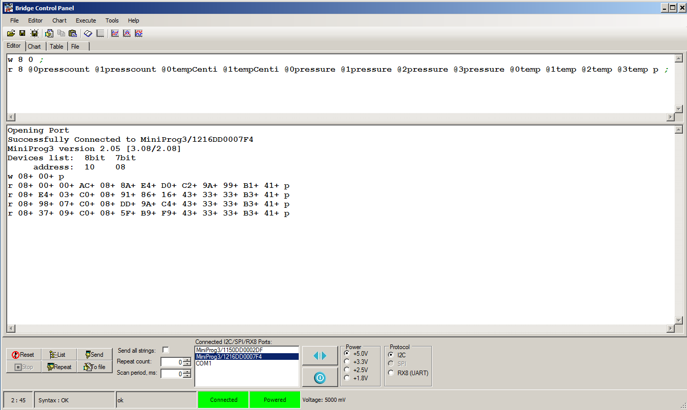
After setting up the variables, I first make sure that the BCP is talking to the PSoC4 by pressing “list” button on the BCP. When I click that button, the BCP tries to read from all of the 127 valid I2C addresses. If it gets an “ACK”, then it reports that it can talk to that device. On the screen below you can see that it sees “address: 10 08” which is the I2C address of my PSoC4.
The next step is to tell the BCP how to read the EZI2C registers. First I write a 0 to address 8 with the “w 8 0;” command. This sets the “data pointer” t0 0, meaning the start of the register space. I then issue command to read 12 bytes, each byte has a name that corresponds to a byte in the “variables” configured in the previous step. An example is “@0presscount” which corresponds to the least significant byte of the presscount variable and “@1presscount” which corresponds to the most significant byte of the presscount variable.
After setting up the variables, I press “return” to issue the command. The BCP returns “r 08+ 00+ 00+ AC+ 08+ 8A+ E4+ D0+ C2+ 9A+ 99+ B1+ 41+”. What does that mean? The R means that it did a read. The 08+ is the address of the I2C and the + means and “ACK”. Each of the other bytes+ are the other 12 bytes read in the command. I use this website to covert the 4-byte hex float(s) to decimal and I get:
pressCount = 0x0000 : There is 0 volts attached to the input which is true
tempCenti = 0x08AC = 2200 (that makes sense 22.2 degrees c * 100 ~= 2200)
pressure = 0xC2D0E48A = -104.44636535644531 … that makes sense rememberdp.pressure = (((float)dp.pressureCounts)-408)/3.906311:
temp = 0x41b1999A = 22.200000762939453 c = 71.9f [ok that makes sense]
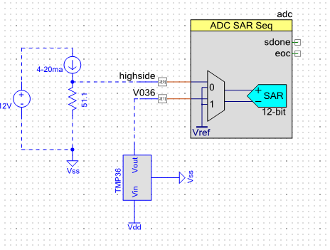
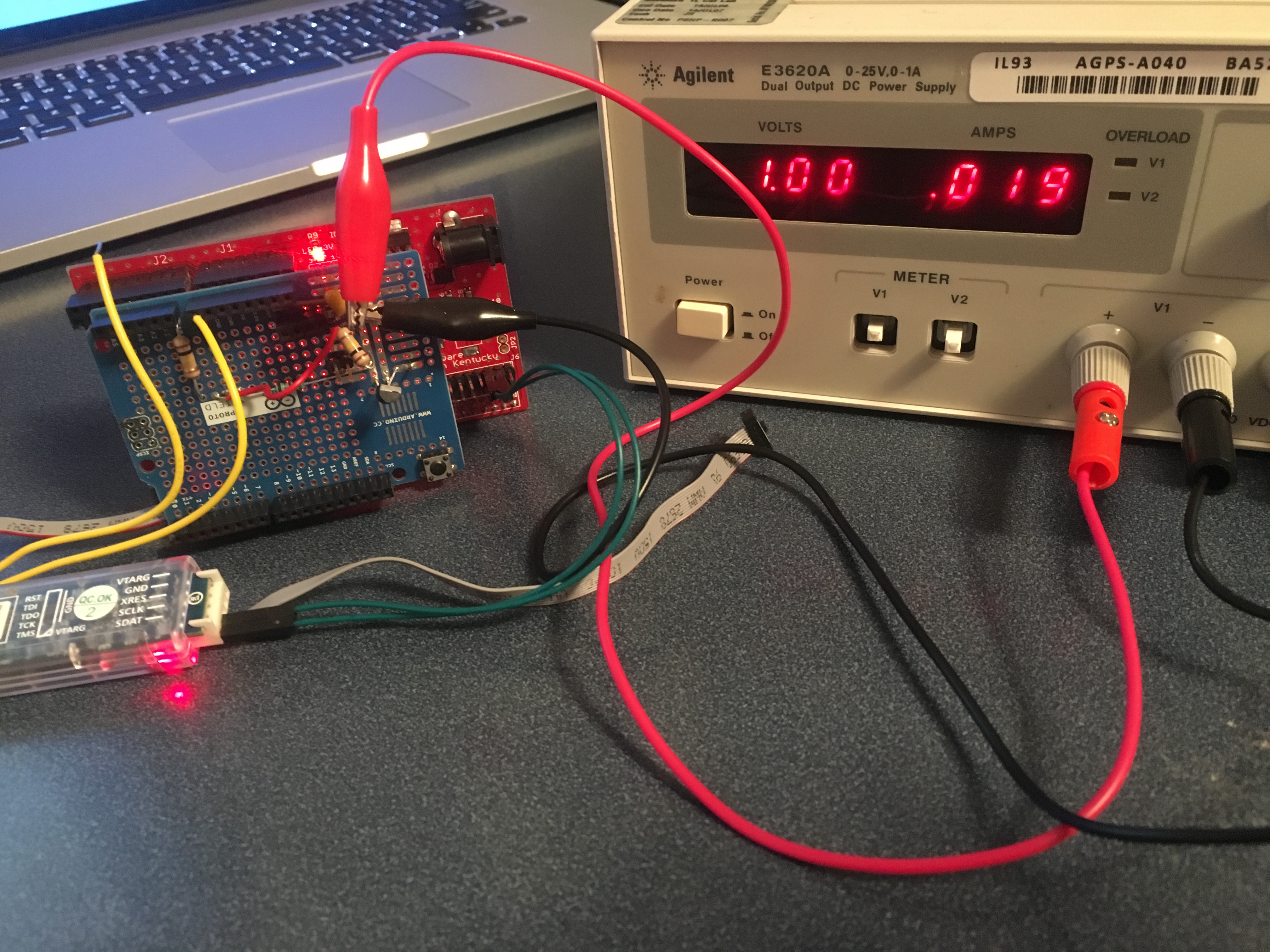
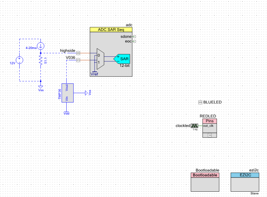
The next step is to attach a bench power supply to the pressure input (I bought this one from eBay). I will use the variable voltage to simulate different pressures. Recall from the schematic that the pressure sensor acts as a current source that is then driven into a 51.1 ohm resistor. Here is the schematic:
With this setup if I put in 0.51V on the “high side” I should get [V=IR] 0.51V = I * 51.1Ohm so I= 0.01 A. You can see from the picture that is what I get (or pretty damn close). When I press return on the bridge control panel (see it in the screen shot above) I get “r 08+ E4+ 03+ C0+ 08+ 91+ 86+ 16+ 43+ 33+ 33+ B3+ 41+” which means
pressCount = 0x03E4 = 996 counts. The range of the ADC is 4096 counts (in single ended mode) and 0 –> 2.048V so 996 counts is 0.498v
tempCenti = 0x08C0 = 2200 (that makes sense 22.2 degrees c * 100 ~= 2200)
temp = 0x41B33333 = 22.399999618530273 c = 72.3f [ok that makes sense]
For the last test of the pressure sensor input I put the variable supply to 1.0V which makes 0.019 mA. Once again V=IR 1V/51.1Ohm = 0.0196 A. Ok Ohms law still works. Then I press return and I get “r 08+ 98+ 07+ C0+ 08+ DD+ 9A+ C4+ 43+ 33+ 33+ B3+ 41+ p”. When I decode that I get
pressCount = 0x0798 = 1944 counts. The range of the ADC is 4096 counts (in single ended mode) and 0 –> 2.048V so 1944 counts is 0.972v (that is pretty damn close)
tempCenti = 0x08C0 = 2240 (that makes sense 22.4 degrees c * 100 ~= 2240)
temp = 0x41B33333 = 22.399999618530273 c = 72.3f [ok that makes sense]
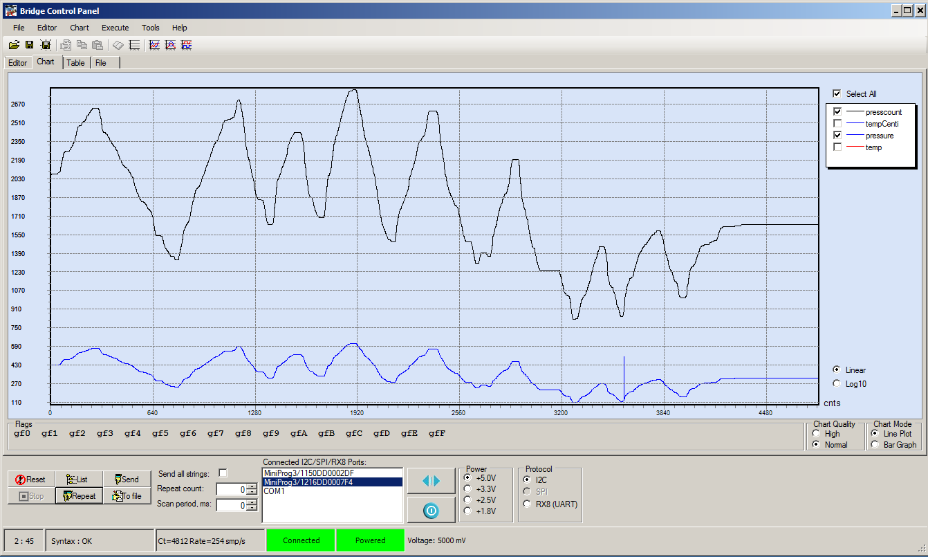
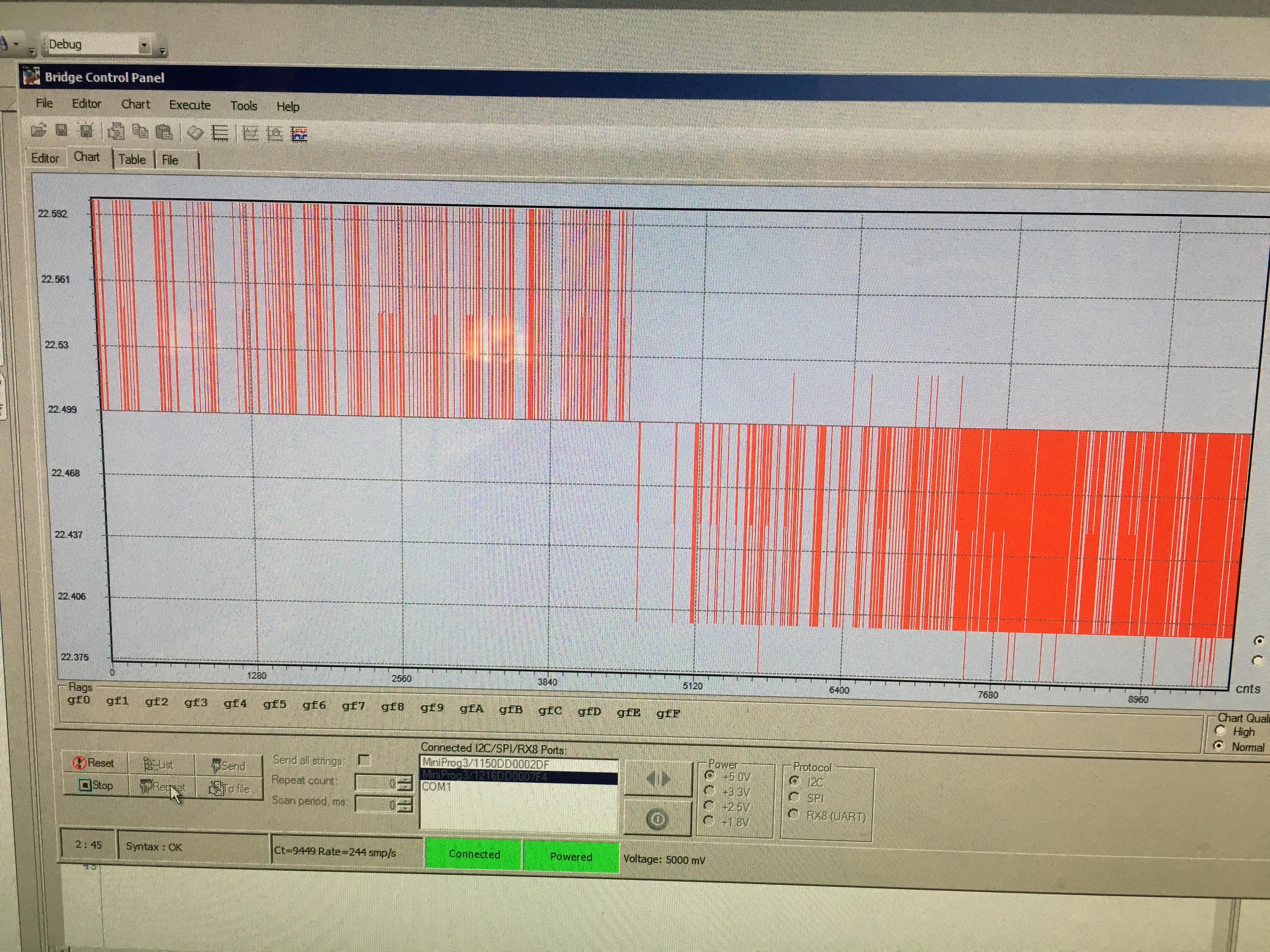
In the next test I will go into graphing mode and use the “repeat” button to run I2C reads as fast as possible. I will then sweep the voltage on the bench power supply and plot the pressure and the counts to make sure that makes sense. It looks good, here is the plot:
In the next test I use a Fluke Thermocouple to verify that the TMP036 is reading the correct temperature. You can see that when I put the thermocouple right on the sensor it reads 23.4 degrees C. I then turned the camera towards the screen and took a picture of the plot. In that plot you can see the temperature bouncing around 22.5. The bounce is +- 1 count (literally noise) of the ADC . I am not sure what the cause of the 0.9 degree difference between the Fluke and the TMP036, it could be several things including the accuracy of the TMP036, the accuracy of the Fluke, the accuracy of the PSoC4 ADC, where I am measuring, etc. But less than a degree really doesn’t matter to me.
In the last test I make a graph of the temperature while I am grabbing the TMP036 which causes the temperature to rise. After a bit of time I let go of the sensor and you can see the temperature fall.
At this point it looks like the bootloader is working and that the PSoC 4 firmware is working. In the next post I will talk about the overall server software architecture.
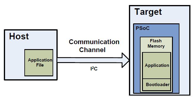
A bootloader is a firmware program that can update the application firmware in an embedded system without using a programmer (like the Miniprog-3). This is a convienient way to fix bugs, release features, etc. without having to be physically at the system. As a developer you can update your design, then create a “hex” file image, then release that image (through email, the internet, etc) to be installed on all of your remote devices. Once your new hex file arrives at the host computer, the bootloader has the job of flashing the new firmware into your system. You can read more detail about bootloading in the excellent Cypress application note AN86526 PSoC4 I2C Bootloader.
In general, bootloaders are triggered by some external event (like a chip reset, a trigger from a GPIO, or a command from the application firmware). The bootloader then listens for communication from a host computer. The host computer could be lots of different things including a cell phone, a central application processor, or an external computer plugged into your system. Once the bootloader starts:
If there is no communication it will generally timeout after a set time, then jump into the application firmware to put the system into normal application mode.
If there is communication, it will copy a new application from the host computer and then write it into the flash in the correct place. There is a special case called a “dual application” boot loader. This provides safety by keeping and old image still in flash in case there is a problem bootloading the new firmware.
Here is a picture of the architecture:
In the Cypress language the bootloadable is an application image that can be bootloaded by the bootloader.
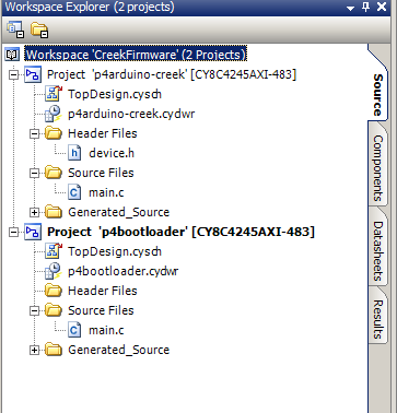
When I am making firmware like this I generally put two projects in the same workspace. One project is the bootloader and the other project is the bootloadable. This is exactly what you will find in in the PSoC Creator workspace called CreekFirmware on github. The first project is called p4arduino-creek which is the main application firmware that I discussed in detail in the previous post.
This bootloader, called p4bootloader, is a simple I2C bootloader. After the chip resets it:
Starts blinking the blue led to indicate that it is in bootloader mode
Waits 10 seconds to hear I2C communication
If there is none then it jumps into the main application (called the bootloadable)
It there is then it starts the boot loading process
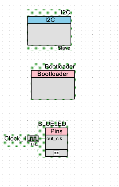
The schematic is simply:
An I2C Slave
A bootloader component
A blinking LED (a clock tied directly to an output pin)
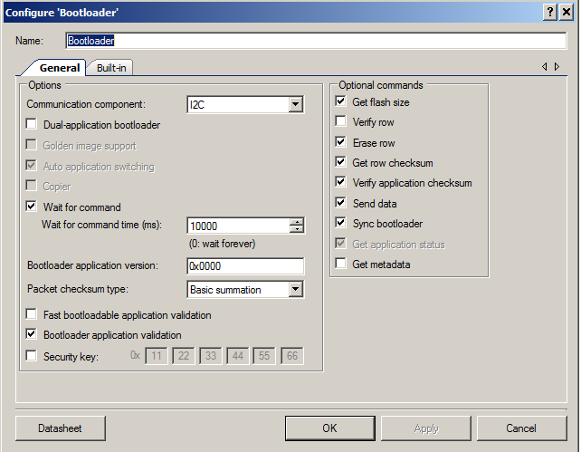
When you configure the bootloader component you need to select which communication interface to use. In this case it is the “I2C”. Then you configure how long you want to wait before timing out and jumping into the main application. In this case 10000ms a.k.a. 10s
The last step is to start the bootloader component in the firmware.
That is it. In the next post I will discuss the steps I took to test the firmware.
In this post I will describe the PSoC Creator schematic and firmware that I built to run the PSoC4. You can find the project on github. After you open the project in PSoC Creator you will find two projects in the workspace explorer:
p4ardino-creek: This project starts running 10 seconds after the chip powers up. It uses PSoC Analog to Digital Convertor to read the pressure sensor and the temperature sensor. It then convert the data to a readable form and stores it into the EZI2C buffer to be read by the Raspberry PI.
p4bootloader: This project runs for 10 seconds when the chip is rebooted. If it detects the Raspberry Pi host trying to load new firmware it will “bootload”. If after 10 seconds it doesn’t hear anything, it will run the p4arduino-creek application. I will describe how the bootloader works in the next post.
p4ardunio-creek
The schematic for this project contains four sections
The Analog to Digital convertor and the “external” schematic of the pressure current loop. The elements in blue are external to the PSoC and are there just for documentation.
The Red and Blue LED pins and the clock that drives the Red LED to blink
The EZI2C which serves as the I2C Slave for the Raspberry Pi to read
The Bootloadable component which allows this project to be boot loaded.
The configuration of each of elements is show below.
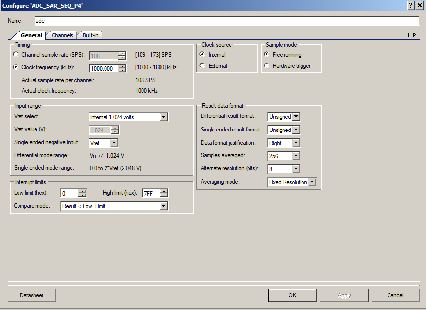
The ADC is configured to run as slowly as possible (1000 SPS). I have also enabled the averaging which automatically averages 256 samples. This effectively makes a low pass filter to remove noise. This is possible because the pressure and temperature move very slowly as compared to the speed at which they are sampled. The SAR ADC in the PSoC is inherently differential, I tell the ADC that I want the negative channel to be connected to a stable VREF. This allows me to measure between 0V and 2*vref = 2.048 volts.
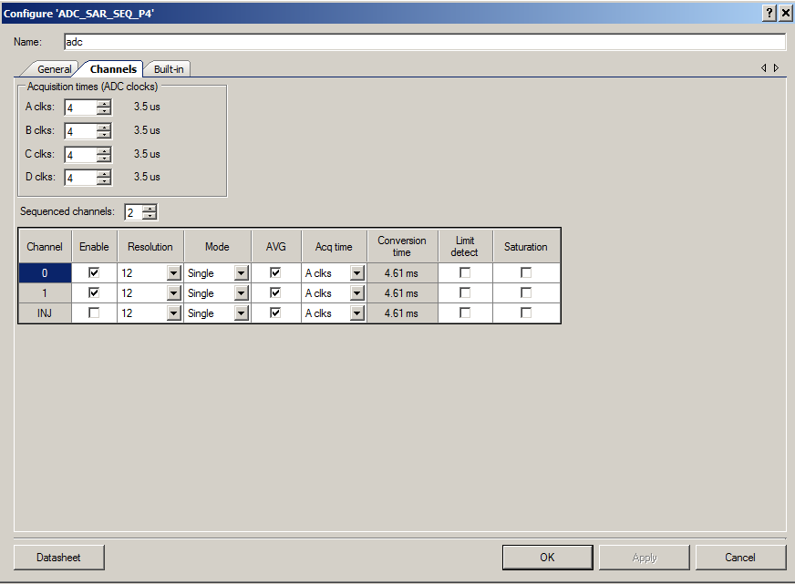
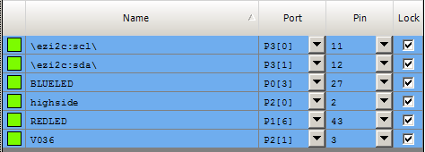
On the ADC channels TAB I enable two channels, both single ended, both with averaging turned on. Channel 0 is connected to the pressure sensor (on Arduino pin A0 = PSoC Pin P2[0]) and channel 1 is connected to the TMP036 (on Arduino pin A1 = PSoC Pin P2[1])
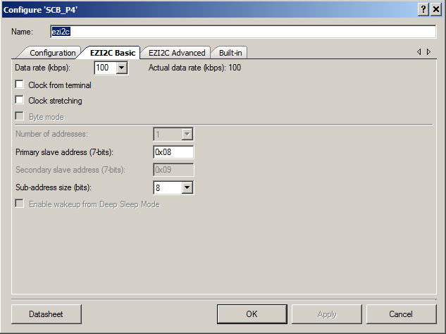
For this design I setup the PSoC4 to act as an EZI2C slave. EZI2C means that the chip follows the EEPROM protocol which many many I2C masters understand. The only thing that I configure in this case is to use the slave address of 0X08.
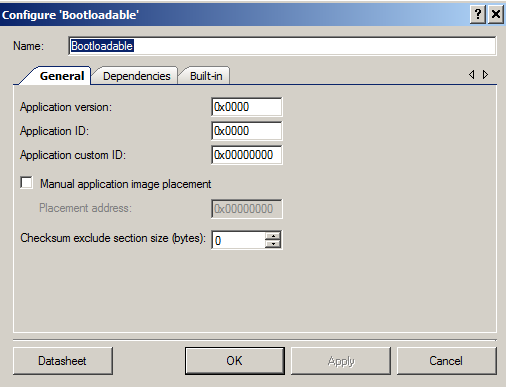
For this project to be compatible with a bootloader it needs the bootloadble component instantiated. In this case I use all of the default configurations. When I make changes to the firmware in the future I will up-rev the version numbers. These settings are here to prevent you from accidentally overwriting and newer rev of the firmware or putting in the wrong application type.
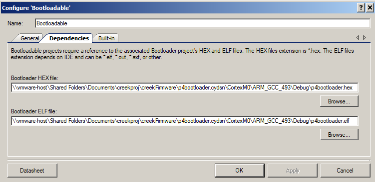
In order for the bootloadable to work I need to tell it where its “bootloader” image resides. Remember from above that I put both projects in the same workspace. So, what I need to do is browse through the directory hierarchy into the bootloader project and selects its ELF and HEX files. If you want to read more about PSoC4 Bootloading you can read AN86526 entitled “PSoC 4 I2C Bootloader”
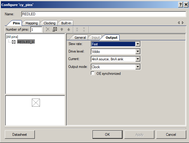
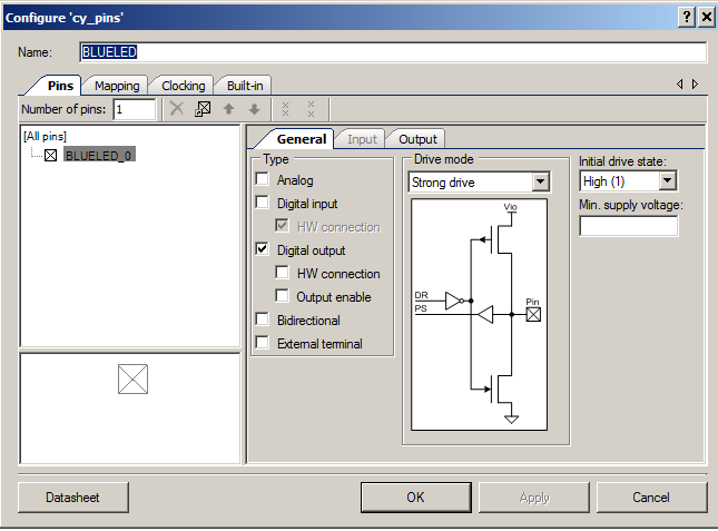
One of the unique features of a PSoC is its ability to do hardware based design. In this design I want a slowly blinking LED to indicate that the system is running. For this task I have to configure the pin to let one of the internal clocks drive it. To make this work you need to selected the output mode as “Clock”.
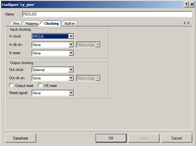
And you need to selected the “Out clock” as external.
Now, I want to turn off the Blue LED. As the LED is active Low, to turn it off you write a 1 to the pin. I do this as part of the setup of the pin by setting the initial drive state to high.
The last step in the device configuration is to select the proper pins on the Design Wide Resources (DWR) pins tab. Not setting the pins correctly is one of the most frequent errors that users make with PSoC Creator.
The firmware for the project is simple. In the first section (lines 3-8) I define a packed structure to serve as the I2C buffer. The __attribute__((packed)) tells the compiler to put all of the members of the structure in contiguous bytes. In the structure I defined below, if I had not marked it is packed, it is likely that the compiler would have put two bytes of padding after the pressureCounts and two bytes after the centiTemp. It would have done this to work align those datatypes to make the memory access more efficient.
The next section (lines 17-23) I initialize the system and start the components.
The the main body of the program (lines 27-43) I ask the ADC if it is done reading the voltages, if not go on, if so then calculate the different values and store them in the I2C buffer. The “CyEnterCriticalSection” prevents an I2C interrupt from reading the buffer before the data is completely written to prevent a partial read of the data.
In the next post I will explain boot loading and the p4bootloader project.


