Now that we have completely tested PRoC and PSoC4200M firmware the next step is to build an iOS App called Example 10. The Xcode project is available in the Xcode directory in the project directory at github.com/iotexpert/cy8ckit-021/
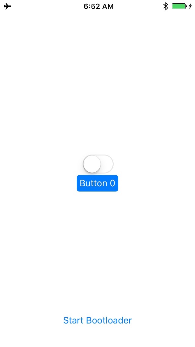
Ill try to build this App to be as simple as possible. Here is what the (single) screen looks like in three different state (nothing pressed, button0 pressed, led0 on):


This App is built up with four files
- ViewController.swift: an object which controls the screen (button clicks)
- BluetoothNeighborhood.swift: an object which controls the Bluetooth in the phone and represents the CY8CKIT021 board (the Model)
- globals.swift: Defines the NSNotifications that can be sent
- Main.storyboard: The screen layout
The code will do the following:
- When the ViewController (VC) starts it will instantiate a BluetoothNeighborhood (BN) object
- VC: Tell the BN to start the bluetooth central in the phone
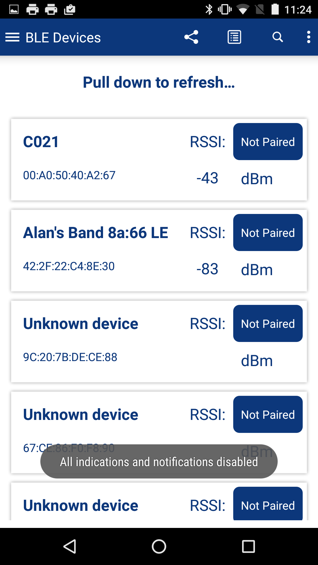
- BN: Scan for BLE Peripherals that are advertising the CY8CKIT-021 Service UUID
- BN: When it hears the peripheral with the correct UUID then connect
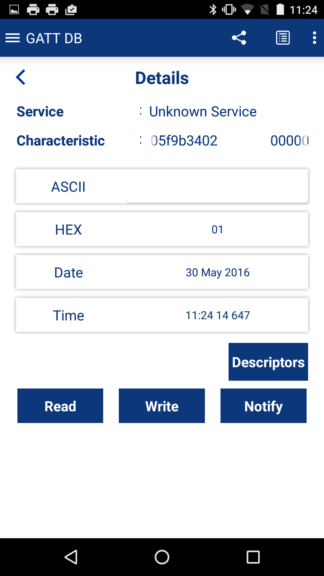
- BN: Read the state of the button0 and led0 then send an NSNotification
- BN: Turn on the notify for button0 (to cause the PRoC to send an NSNotification when there are changes)
- VC: update the screen when it gets the NSNotification from (5)
- VC: If the LED0 switch on the screen is switched then tell the BN to write to the PRoC
- BN: If the button0 is changed then send an NSNotification to the VC
- VC: If there is an NSNotification (9) of a button0 change then update the screen
- VC: If the bootloader button is pressed tell the BN to write the bootloader characteristic
- BN: If there is a disconnect event then send an NSNotification to the VC to disable the GUI elements and start scanning again (step 3)
ViewController.swift
The viewDidLoad method runs when the Apps starts and loads the first screen. This method
- Initializes the BluetoothNeighborhood object
- Tell it to start the bluetooth scanning
- Disables the UI buttons
- Then registers with the NSNotificationCenter that it wants to hear the 4 possible messages that the model can send
- Connect: enable the buttons
- Disconnect: disable the buttons
- UpdateLED: reflect the current state of the LED on the screen
- UpdateButton: reflect the current state of the button on the screen
//
//  ViewController.swift
//  Example10
//
// Project: Example10
// Kit: CY8CKIT-021 Sheild
// Baseboard: CY8CKit-44 PSoC4M
//
//  This file contains the viewcontroller for the single view application.
//  Basically when it loads you startup and connect to the bleboard
//  then display the state of things... or let the user flip the switch
//

import UIKit

class ViewController: UIViewController {

    var bleLand : BlueToothNeighborhood!

    override func viewDidLoad() {
        super.viewDidLoad()

        // bleLand-BlueToothNeighborhood is the model.  It is capable of finding
        // a CY8CKIT021 and connecting to it. It can also read/write etc
        bleLand = BlueToothNeighborhood()
        bleLand.startUpCentralManager()

        // start with the switch disabled.  it will turn on once there is a connection
        led0switch.userInteractionEnabled = false
        bootLoaderButton.userInteractionEnabled = false


        // The global structure CY8CKITNotifications defines the different notificateions
        // that can come from the bleLand model.  Basically a connection/disconnection or
        // and update of the Led0 or Button0 State

        // If you get a complete connection then turn on the buttons to start working
        NSNotificationCenter.defaultCenter().addObserverForName(CY8CKIT021Notifications.ConnectionComplete, object: nil, queue: NSOperationQueue.mainQueue()) { _ in
            self.led0switch.userInteractionEnabled = true
            self.bootLoaderButton.userInteractionEnabled = true
        }

        // if you get disconnected then turn off the buttons
        NSNotificationCenter.defaultCenter().addObserverForName(CY8CKIT021Notifications.DisconnectedDevice, object: nil, queue: NSOperationQueue.mainQueue()) { _ in
                self.led0switch.userInteractionEnabled = false
                self.bootLoaderButton.userInteractionEnabled = false
            }

        // The we got feedback from the model about the state of the button0
        NSNotificationCenter.defaultCenter().addObserverForName(CY8CKIT021Notifications.UpdatedButton0, object: nil, queue: NSOperationQueue.mainQueue()) { _ in self.button0.selected = self.bleLand.button0State }

        // The we got feedback from the model about the state of the led0
        NSNotificationCenter.defaultCenter().addObserverForName(CY8CKIT021Notifications.UpdateLed0, object: nil, queue: NSOperationQueue.mainQueue()) { _ in self.updateLed0() }

    }
The GUI part of the code just acts when the button/switch is pressed to send messages to the model. These methods are linked to the GUI elements on the main.storyboard
    // This function grabs the current button0 state from the model and sets the button
    // to indicate it is either being pressed or not
    func updateButton0()
    {
        self.button0.selected = self.bleLand.button0State
    }

    // This functiong rabs the current led0 state from the model and then flips the
    // switch the right way
    func updateLed0()
    {
        led0switch.on = bleLand.led0State
    }

    @IBOutlet weak var button0: UIButton!
    @IBOutlet weak var led0switch: UISwitch!

    // When the user flips the switch you need to write the updated value to the model
    @IBAction func led0SwitchAction(sender: UISwitch) {

            bleLand.writeLed0Characteristic(sender.on)
    }

    // If the user presses the bootload button then send the bootload command
    // this will cause and immediate BLE disconnect... etc
    @IBOutlet weak var bootLoaderButton: UIButton!
    @IBAction func startBootLoader(sender: AnyObject) {
        bleLand.startBootloader()
    }
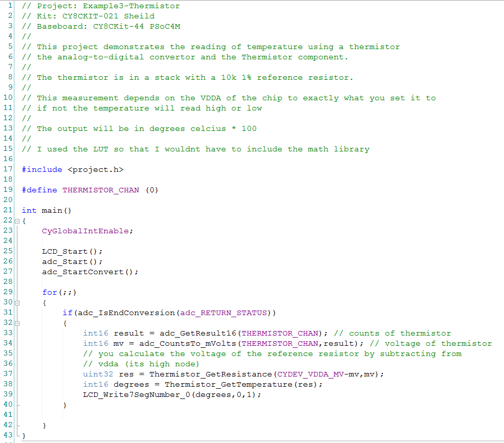
BluetoothNeighborhood
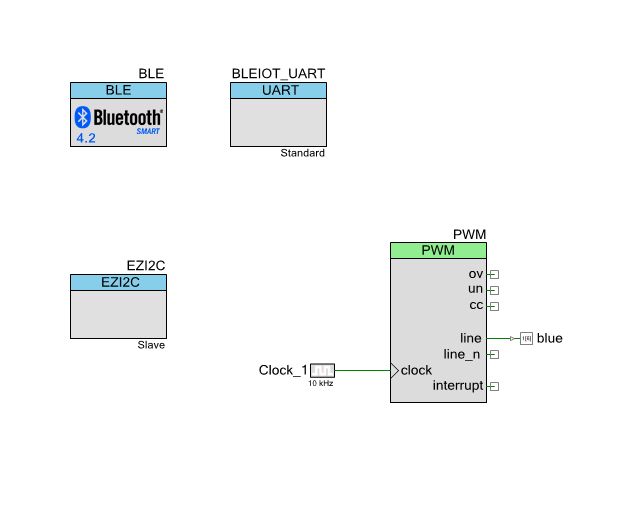
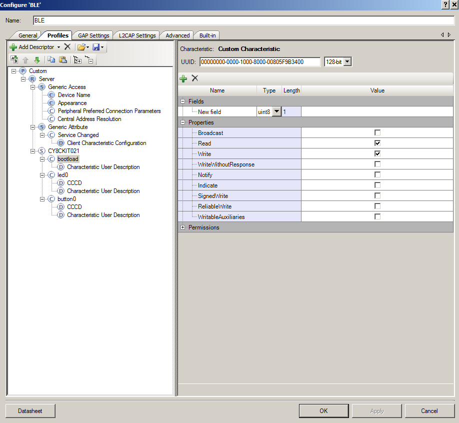
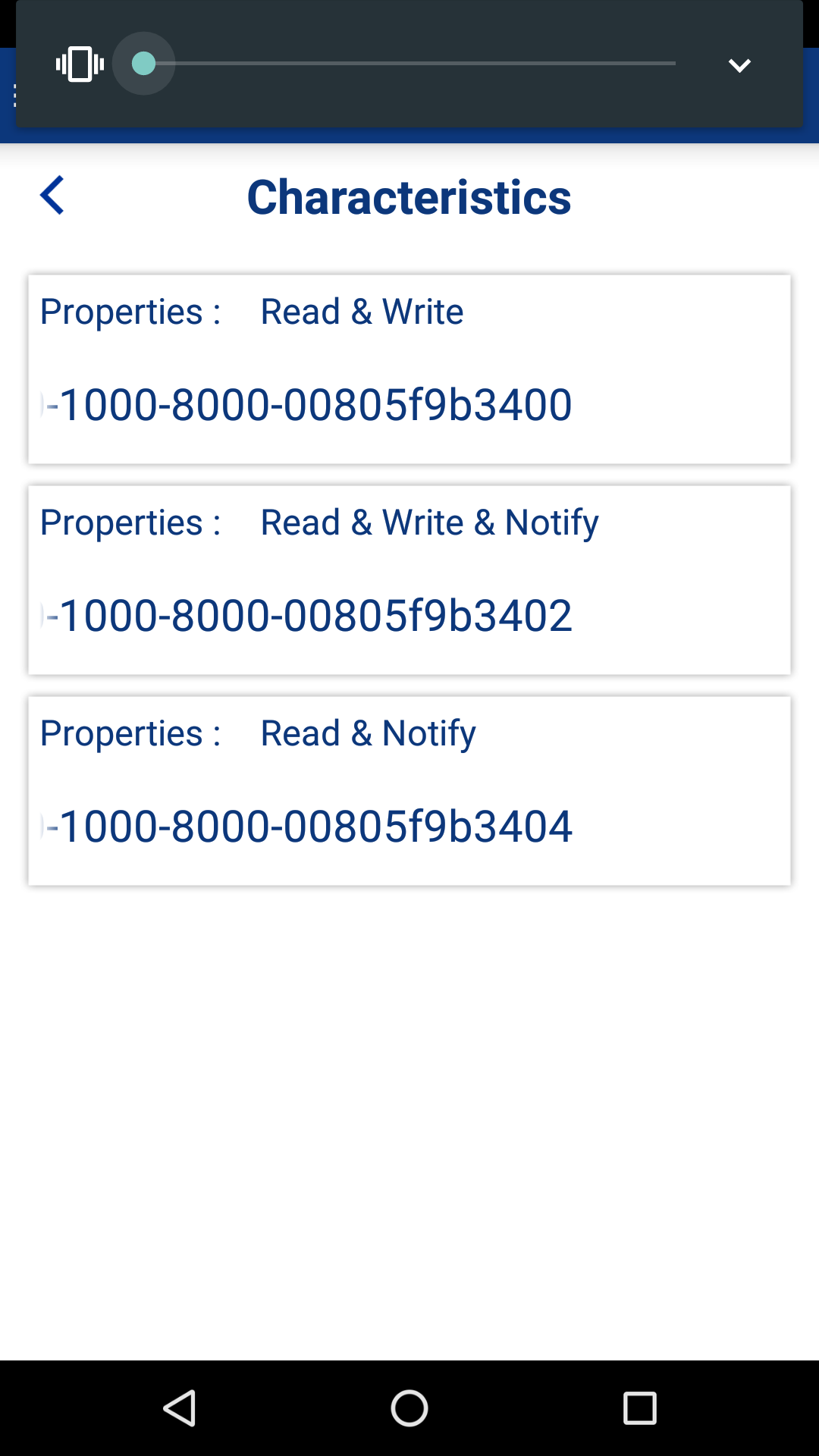
This file contains all of the code that interacts with the CY8CKIT021 board. The first block of code defines a structure with a list of the UUIDs that we need to search for. These are defined in the Bluetooth Component Customizer from the PRoC firmware.
// BlueToothNeighborhood.swift
//
// Project: Example10
// Kit: CY8CKIT-021 Sheild
// Baseboard: CY8CKit-44 PSoC4M
//
// This file contains the model for the CY8CKIT021 board with 1 LED0 and 1 Button 0
//

import CoreBluetooth


// This structure conatains the UUIDS for the services and characteristics on the board
// it MUST match what you defined in the creator BLE Configuration Wizard
private struct BLEParameters {
    static let CY8CKIT021Service = CBUUID(string: "00000000-0000-1000-8000-00805F9B3400")
    static let bootloadCharactersticUUID = CBUUID(string:"00000000-0000-1000-8000-00805F9B3401")
    static let ledCharactersticUUID = CBUUID(string:"00000000-0000-1000-8000-00805F9B3402")
    static let buttonCharactersticUUID = CBUUID(string:"00000000-0000-1000-8000-00805F9B3404")

}
The next block of code
// The model for the board
// The BlueToothNeighborhood has BOTH the board model and the Bluetooth model.  This
// makes the code slightly simpler to explain but is a bit weird architectururally
class BlueToothNeighborhood: NSObject, CBCentralManagerDelegate, CBPeripheralDelegate  {

    private var centralManager : CBCentralManager!
    private var CY8CKIT021Board : CBPeripheral?
    private var CY8CKIT021Service : CBService!
    private var led0Characteristic : CBCharacteristic!
    private var button0Characteristic : CBCharacteristic!
    private var bootloadCharacteristic : CBCharacteristic!

    // This function is called by the main view controller to get things going
    func startUpCentralManager() {
        centralManager = CBCentralManager(delegate: self, queue: nil)
    }

    // This is the bluetooth delegate function
    @objc func centralManagerDidUpdateState(central: CBCentralManager) {
        switch (central.state) {
        case .PoweredOff: break
        case .PoweredOn:
            print("Bluetooth is on - Starting scan")
            // start scanning for a device that we can talk to
            centralManager.scanForPeripheralsWithServices([BLEParameters.CY8CKIT021Service], options: [CBCentralManagerScanOptionAllowDuplicatesKey:false])

        case .Resetting: break
        case .Unauthorized: break
        case .Unknown:break
        case .Unsupported:break
        }
    }

    // This delegate function is called by the bluetooth when it finds a device
    // that matches our UUID that we told it when we started the scan
    func centralManager(central: CBCentralManager, didDiscoverPeripheral peripheral: CBPeripheral, advertisementData: [String : AnyObject], RSSI: NSNumber)
    {
        // if you already are connected to a device ignore this one
        if CY8CKIT021Board == nil {
            print("Found a new Periphal advertising CY8CKIT021 Service")
            CY8CKIT021Board = peripheral
            centralManager.stopScan()
            centralManager.connectPeripheral(CY8CKIT021Board!, options: nil)
        }
    }

    // This delegate is called when a device connection is complete
    func centralManager(central: CBCentralManager, didConnectPeripheral peripheral: CBPeripheral) {
        print("Connection complete \(CY8CKIT021Board) \(peripheral)")
        CY8CKIT021Board!.delegate = self
        CY8CKIT021Board!.discoverServices(nil)
    }

    // This delegate is called after the service discovery is complete
    func peripheral(peripheral: CBPeripheral, didDiscoverServices error: NSError?) {
        print("discovered services")
        for service in peripheral.services! {
            print("Found service \(service)")
            if service.UUID == BLEParameters.CY8CKIT021Service {
                CY8CKIT021Service = service // as! CBService
            }
        }
        CY8CKIT021Board!.discoverCharacteristics(nil, forService: CY8CKIT021Service)
    }


    // This delegate is called when the characteristic discovery is complete
    func peripheral(peripheral: CBPeripheral, didDiscoverCharacteristicsForService service: CBService, error: NSError?) {
        for characteristic in service.characteristics!
        {

            print("Found characteristic \(characteristic)")
            switch characteristic.UUID {
            case BLEParameters.buttonCharactersticUUID: button0Characteristic = characteristic
            case BLEParameters.ledCharactersticUUID: led0Characteristic = characteristic
            case BLEParameters.bootloadCharactersticUUID: bootloadCharacteristic = characteristic
            default: break
            }
        }

        // You have a complete connection... so find out the current state of the LED0
        // and Button.. then notify the viewcontroller that things are rolling

        // read the led0 characteristic to find out its current state
        CY8CKIT021Board?.readValueForCharacteristic(led0Characteristic)

        // read the button0 characteristic to find out its current state
        CY8CKIT021Board?.readValueForCharacteristic(button0Characteristic)

        CY8CKIT021Board!.setNotifyValue(true, forCharacteristic: button0Characteristic)
        NSNotificationCenter.defaultCenter().postNotificationName(CY8CKIT021Notifications.ConnectionComplete, object: nil)
    }

    // disconnected device - start scanning again
    func centralManager(central: CBCentralManager, didDisconnectPeripheral peripheral: CBPeripheral, error: NSError?) {
        print("Disconnected \(peripheral)")
        CY8CKIT021Board = nil
        NSNotificationCenter.defaultCenter().postNotificationName(CY8CKIT021Notifications.DisconnectedDevice, object: nil)
        centralManager.scanForPeripheralsWithServices([BLEParameters.CY8CKIT021Service], options: [CBCentralManagerScanOptionAllowDuplicatesKey:false])

    }
The last block of code is responsible for interacting with the board
// start the bootloader...this will cause an immediate disconnect by the board
    func startBootloader()
    {
        var val: UInt8 = 1 // it doesnt matter the value... any write will cause the bootloader to start
        let ns = NSData(bytes: &val, length: sizeof(UInt8))
        CY8CKIT021Board!.writeValue(ns, forCharacteristic: bootloadCharacteristic, type: CBCharacteristicWriteType.WithResponse)
    }


    // a helper function to write the the device
    func writeLed0Characteristic(state: Bool)
    {
        var val : Int8
        if(state)
        {
            val = 1
        }
        else
        {
            val = 0
        }
        let ns = NSData(bytes: &val, length: sizeof(Int8))
        CY8CKIT021Board!.writeValue(ns, forCharacteristic: led0Characteristic, type: CBCharacteristicWriteType.WithResponse)
    }

    // this is the model of the board
    var button0State : Bool = false
    var led0State : Bool = false // assume that it is off

    // This delegate function is called when an updated value is received from the Bluetooth Stack
    func peripheral(peripheral: CBPeripheral, didUpdateValueForCharacteristic characteristic: CBCharacteristic, error: NSError?) {
        if characteristic == button0Characteristic {
            var out: UInt8 = 0
            characteristic.value!.getBytes(&out, length:sizeof(UInt8))
            if(out == 0)
            {
                button0State = false
            }
            else
            {
                button0State = true
            }
            NSNotificationCenter.defaultCenter().postNotificationName(CY8CKIT021Notifications.UpdatedButton0, object: nil)
        }

        if characteristic == led0Characteristic {
            var out: NSInteger = 0
            characteristic.value!.getBytes(&out, length:sizeof(UInt8))
            if(out == 0)
            {
                led0State = false
            }
            else
            {
                led0State = true
            }
            NSNotificationCenter.defaultCenter().postNotificationName(CY8CKIT021Notifications.UpdateLed0, object: nil)
        }
    }
In the next post Ill show you how to build the Android App.
index
description
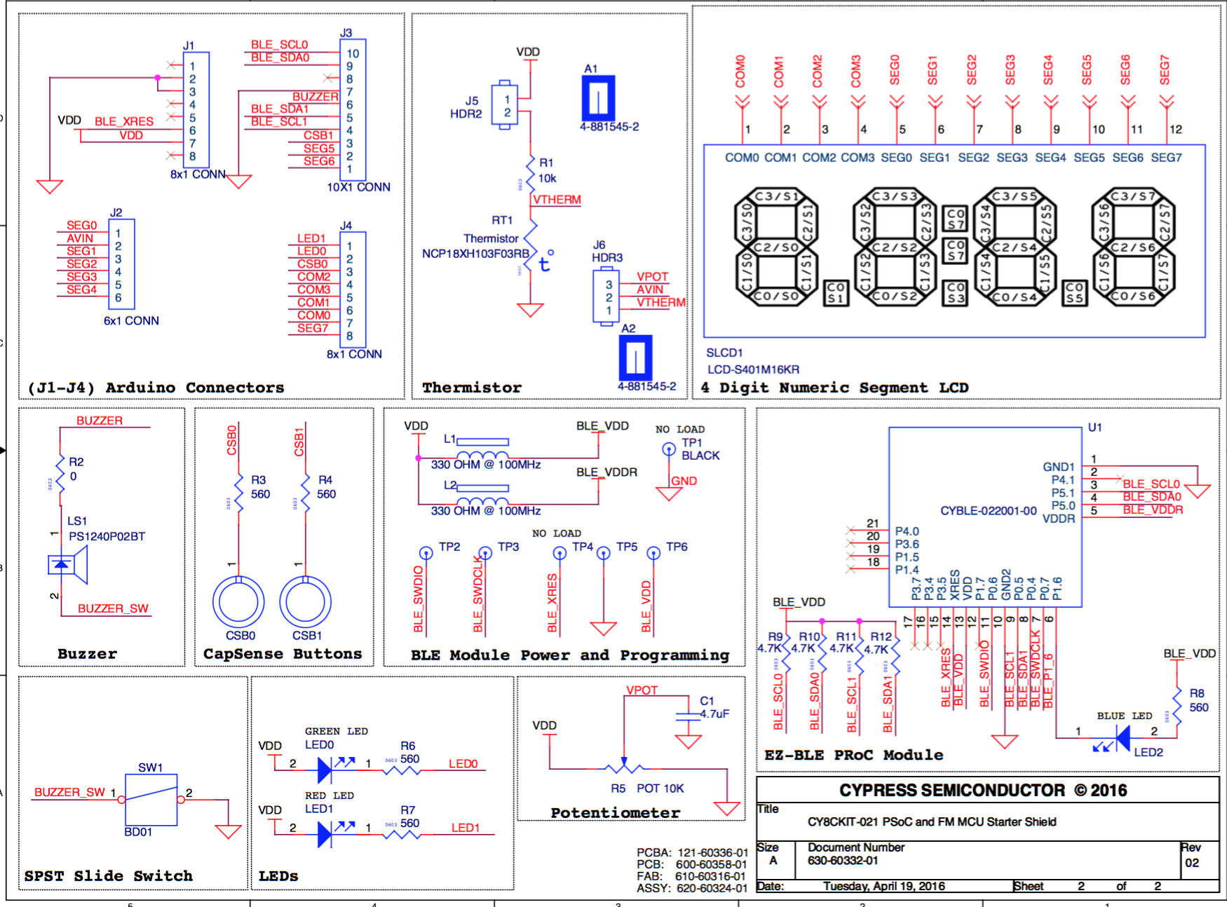
CY8CKIT-021: A Simple FM/PSoC + BLE Demonstration Board
Introduction to CY8CKIT021
CY8CKIT-021: The first four example projects
Use the LEDs
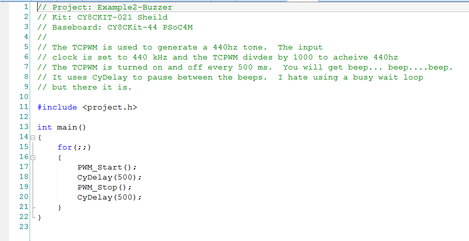
Buzzer
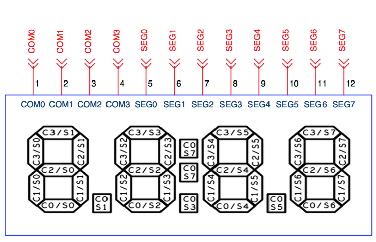
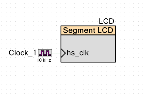
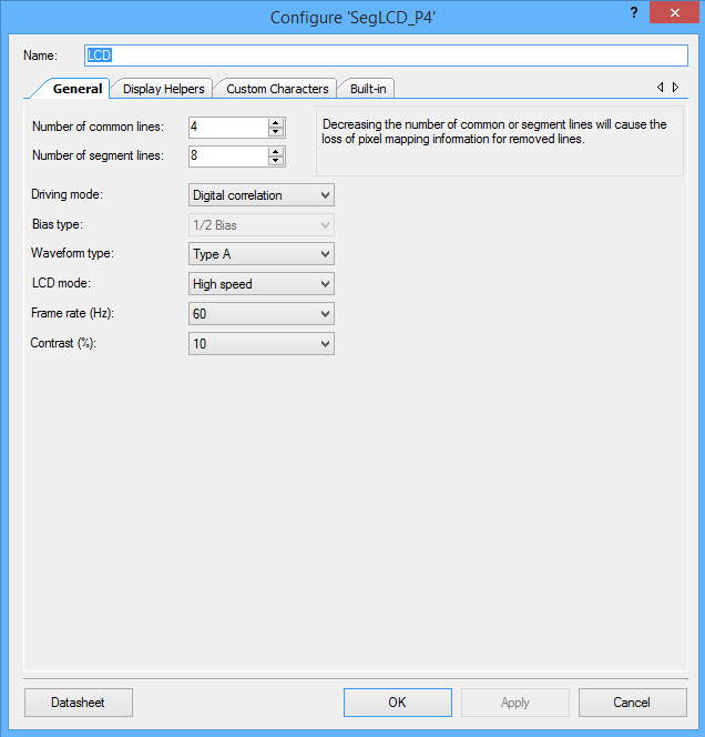
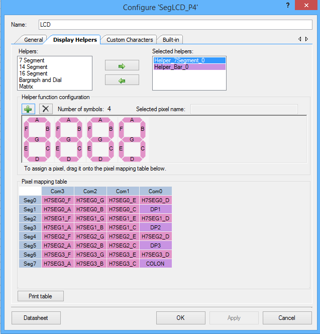
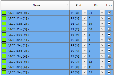
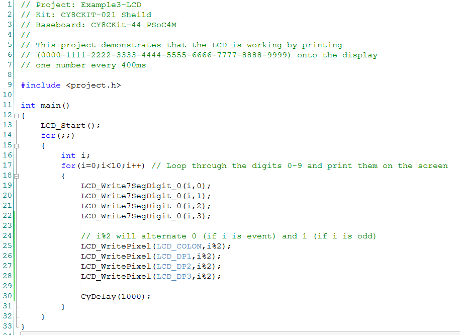
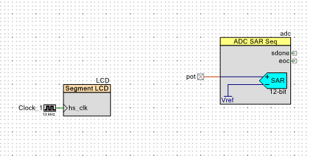
7-Segment display and the Potentiometer
CY8CKIT-021: The next three example projects
Use theThermistor and two Capsense Examples
CY8CKIT-021: Bootloading the PRoC
How to put firmware into the PRoC
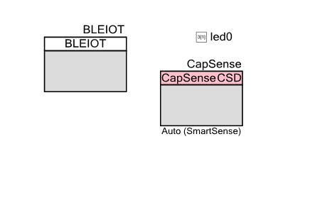
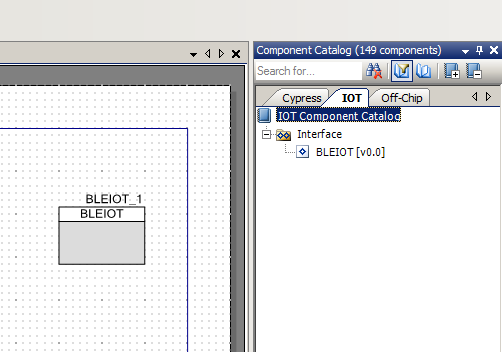
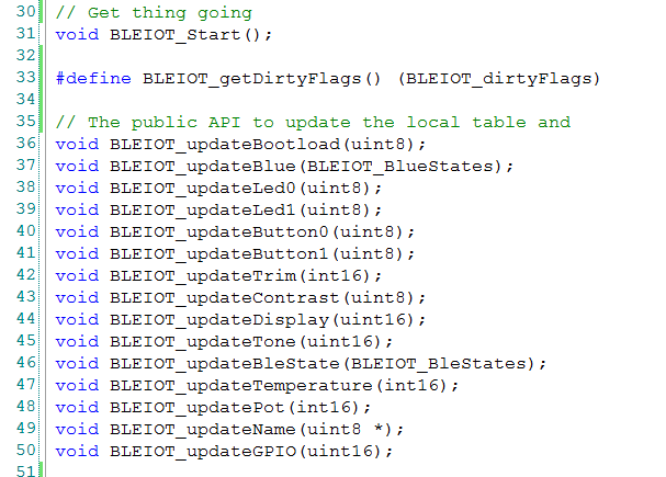
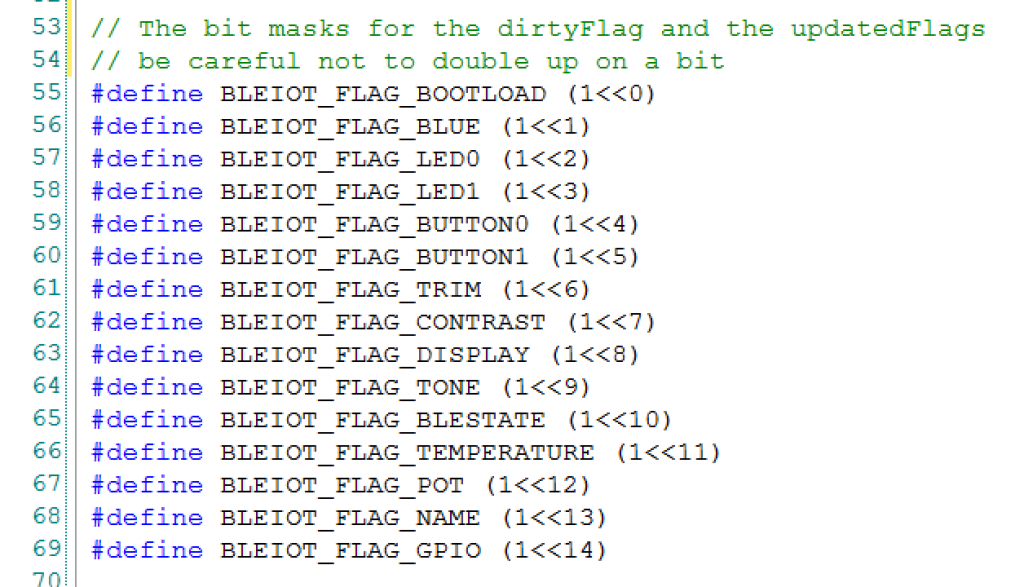
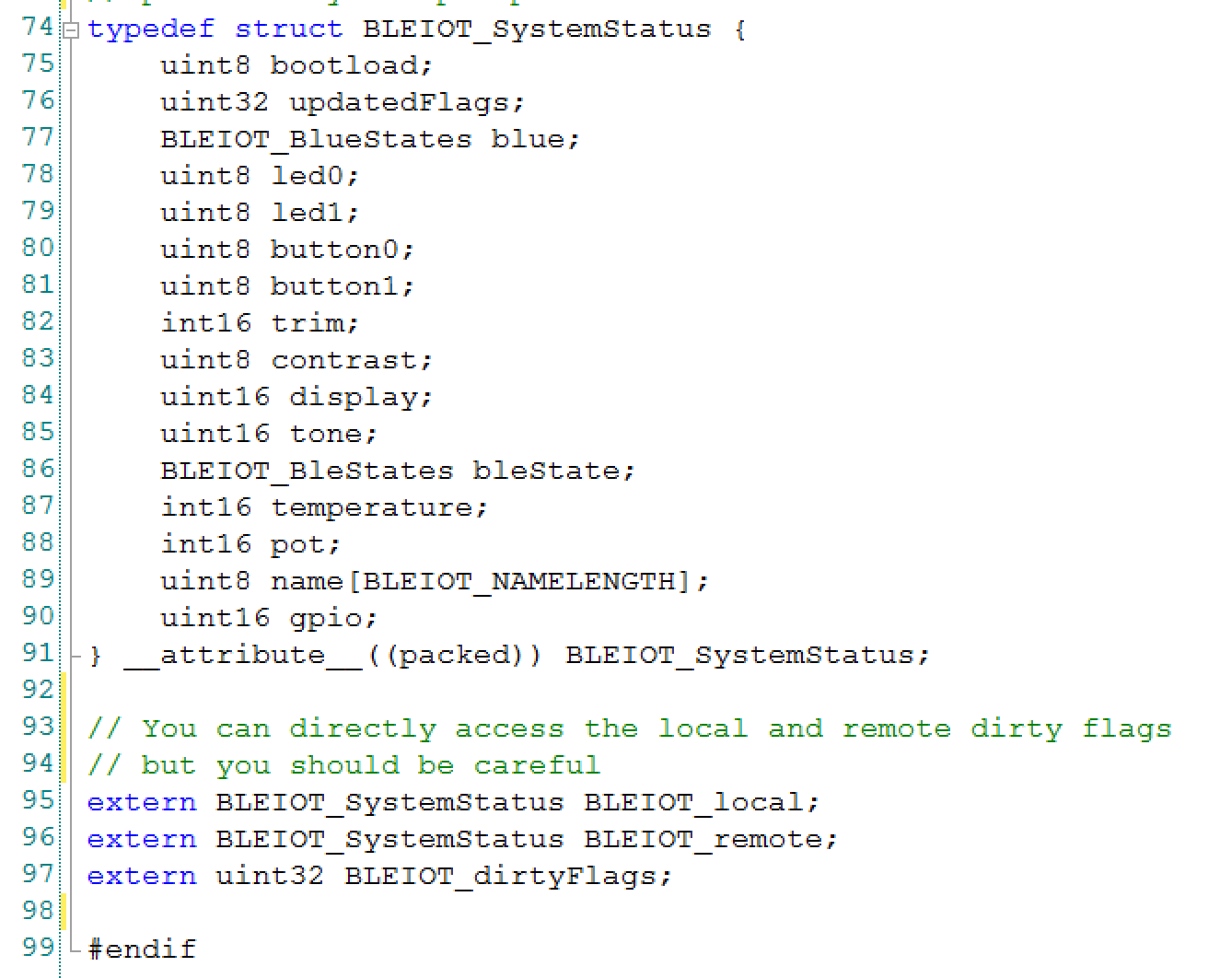
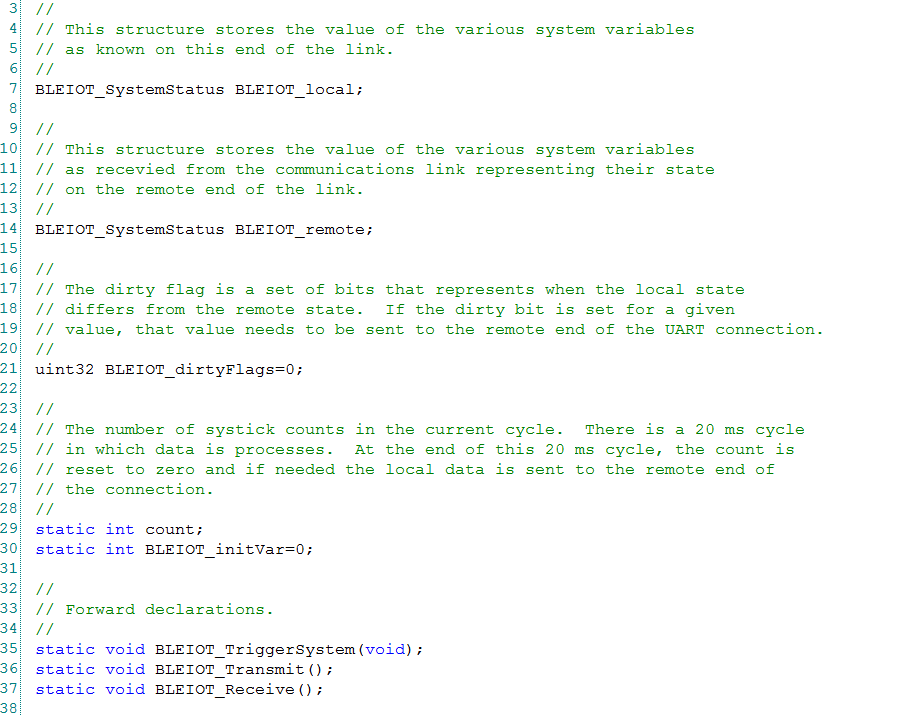
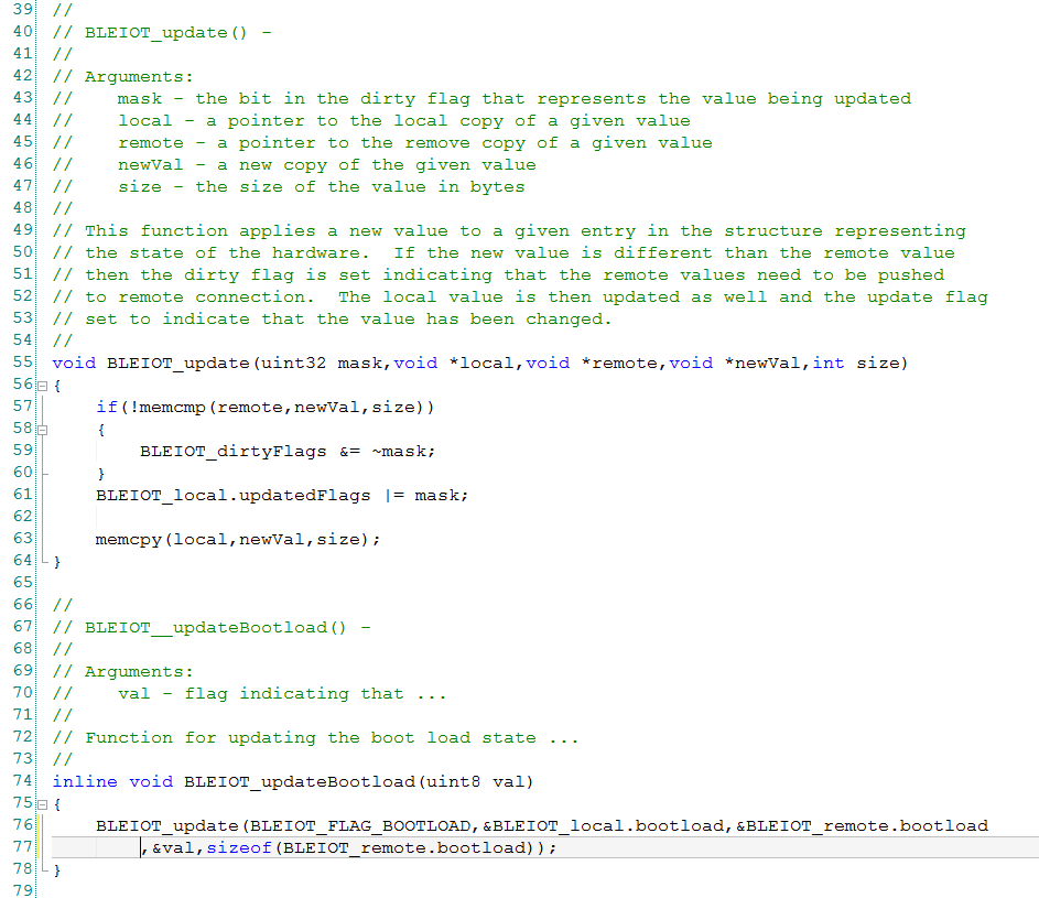
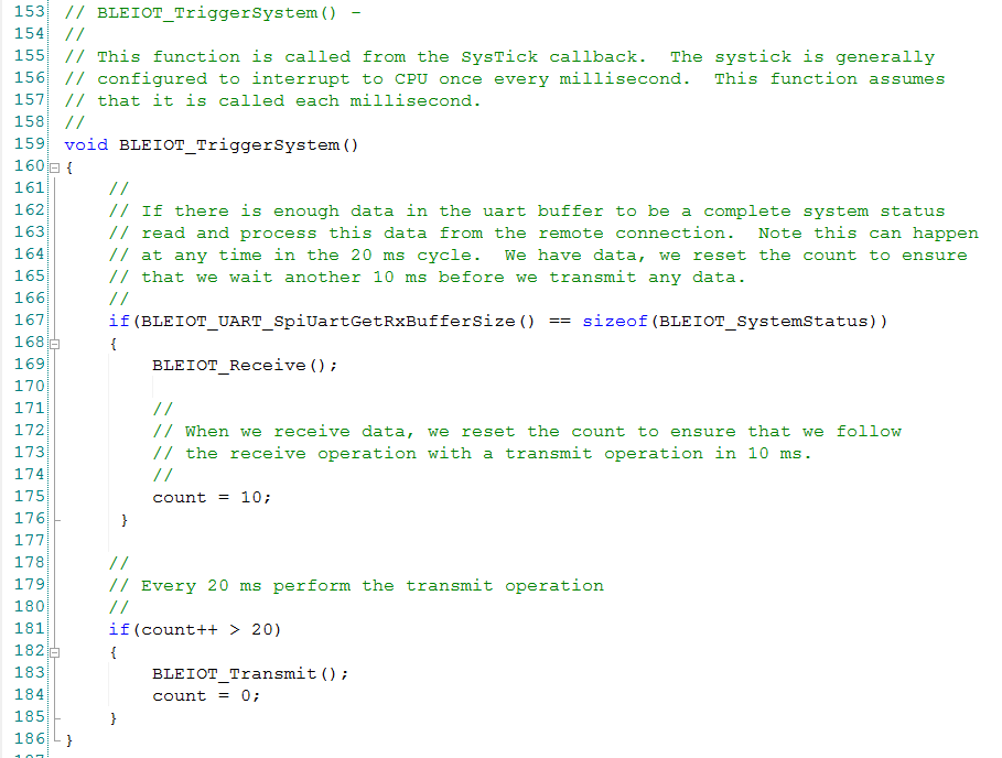
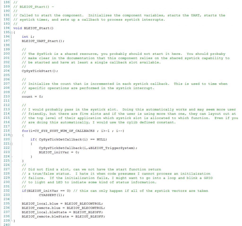
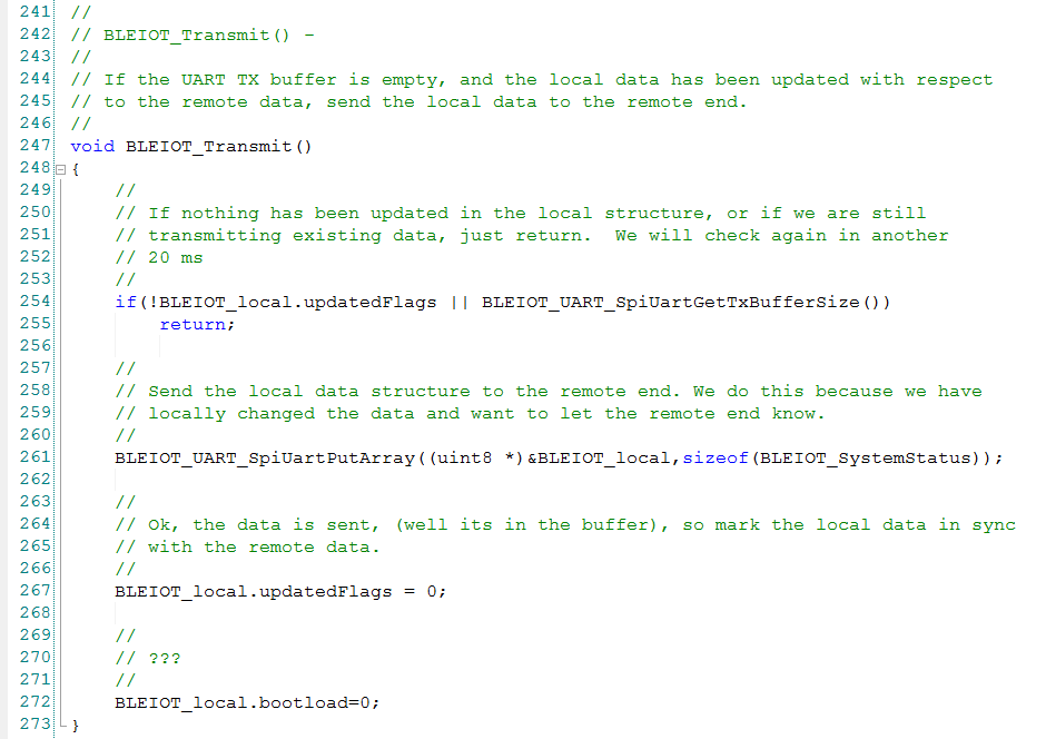
CY8CKIT-021: The BLEIOT Component
A custom component to communicate with the PRoC/PSoC
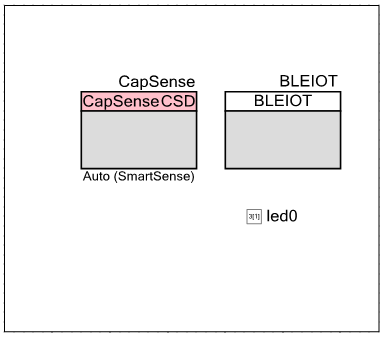
CY8CKIT-021: Using the BLEIOT Component
A full example of the tho MCUs talking
CY8CKIT-021: The PRoC BLE Firmware
How to make PRoC Firmware and use it with the BLEIOT Component
CY8CKIT-021: Example 10 - the new IOS App
How to build and IOS App to talk to the development kit