In the previous three posts I created a Music Player component by building the symbol+schematics, making a public interface, and writing the firmware. In this post I will show you the test program called “MusicTestComponent”.
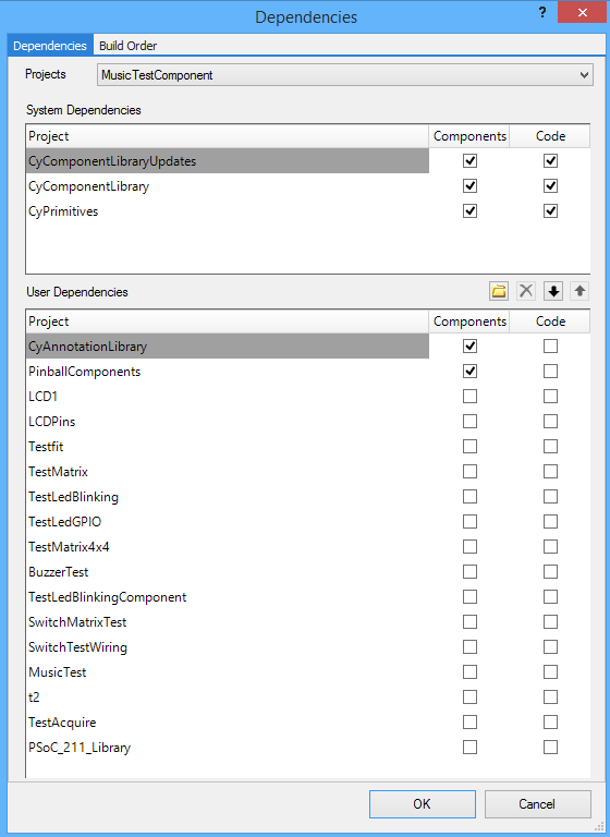
In order to get access to the PinballComponents library project I first right click on my project and edit the dependencies. Specifically, I click on the box that adds the “PinballComponents” as a dependency of the MusicTestComponent project.
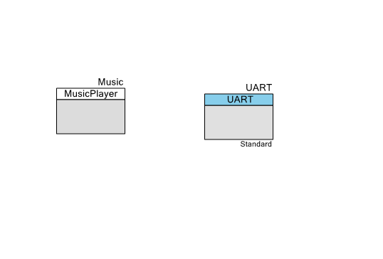
After setting up the dependencies you can then make a schematic with the MusicPlayer and a UART. The UART will be used to trigger commands to be sent to the MusicPlayer Component.
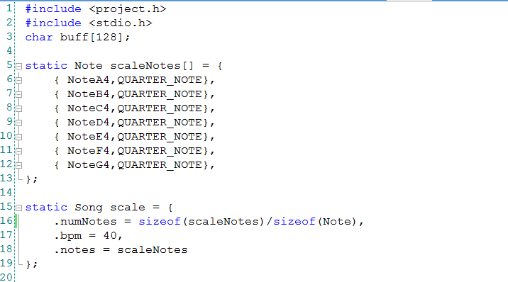
I start the main firmware by creating a test song called “scaleNotes” (lines 5-12). I then turn that array of Notes into a Song by declaring a Song and adding the scaleNotes to the song (lines 15-19).
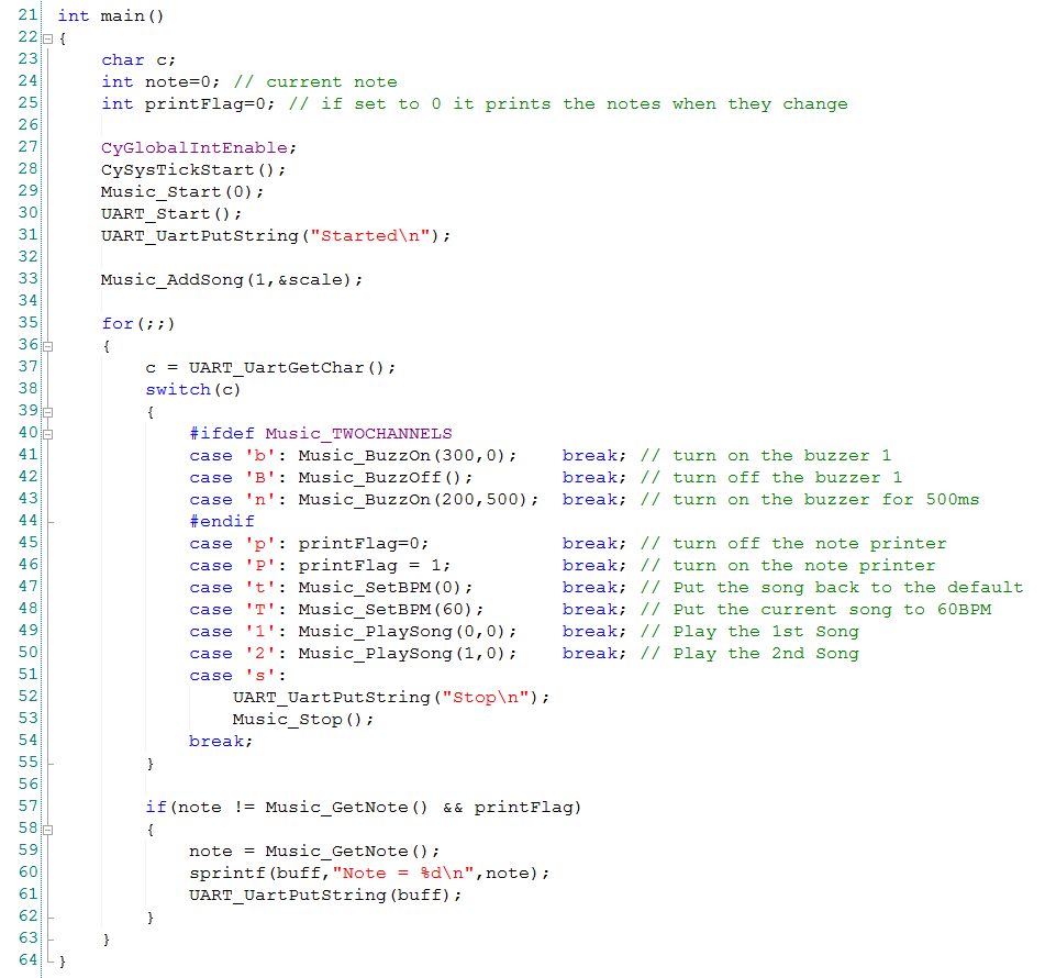
At the start of the program I turn on the interrupts and start the components (line 27-31). Then I add my song to the component (so that it can play it) with line 33.
In the main loop of the program I grab characters from the UART and issue commands to the MusicPlayer component based on what button the users presses.
On lines 57-62 I have a debugging pinout that prints out the currently playing note number each time the note changes.
Thats it. In the next post I will start taking you through the process of designing the printed circuit board.
You can find all of the source code and files at the IOTEXPERT site on github.
Index
Description
Pinball: Newton's Attic Pinball
An introduction to the project and the goals
Pinball: Lotsa Blinking LEDs
Everyone needs a bunch of LEDs on their Pinball Machine
Pinball: Matrix LEDs (Part 1)
Saving PSoC pins by using a matrix scheme
Pinball: Matrix LEDs (Part 2)
Solving some problems with the matrix
Pinball: Matrix LEDs Component
How to turn the Matrix LED into a component
Pinball: A Switch Matrix
Implementing a bunch of switches
Pinball: Switch Matrix Component (Part 1)
The switch matrix component implementation
Pinball: Switch Matrix Component (Part 2)
The firmware for matrix component
Pinball: Switch Matrix Component (Part 3)
Test firmware for the matrix component
Pinball: The Music Player (Part 1)
The schematic and symbol for a Music Player component
Pinball: The Music Player (Part 2)
The Public API for the Music Player component
Pinball: The Music Player (Part 3)
The firmware to make the sweet sweet music
Pinball: The Music Player (Part 4)
The test program for the music player
Pinball: The Motors + HBridge
Using an Bridge to control DC Motors
Pinball: The Eagle Schematic
All of the circuits into an Eagle schematic
Pinball: The Printed Circuit Board 1.0
The first Eagle PCB layout of the printed circuit board
Pinball: The PCB Version 1.0 Fail
Problems with the first version of the Eagle PCB layout
Pinball: PCB Layout 1.2 Updates using Eagle
Fixing the errors on the first two versions of the Eagle PCB
Pinball: Assemble and Reflow the 1.2 PCB
Assembling the Eagle PCB
Pinball: Testing the Eagle PCB
Firmware to test the newly built Pinball printed circuit board
Pinball: Debugging the Motor Driver
Fixing the motor driver PSoC project
Pinball: Hot-Air Reworking the Accelerometer Solder
Using a Hot-Air Rework tool to reflow a QFN
Pinball: Debugging the LM317 Power Supply- A Tale of Getting Lucky
Debugging the LM317/LM117 power supply
No comment yet, add your voice below!