Summary
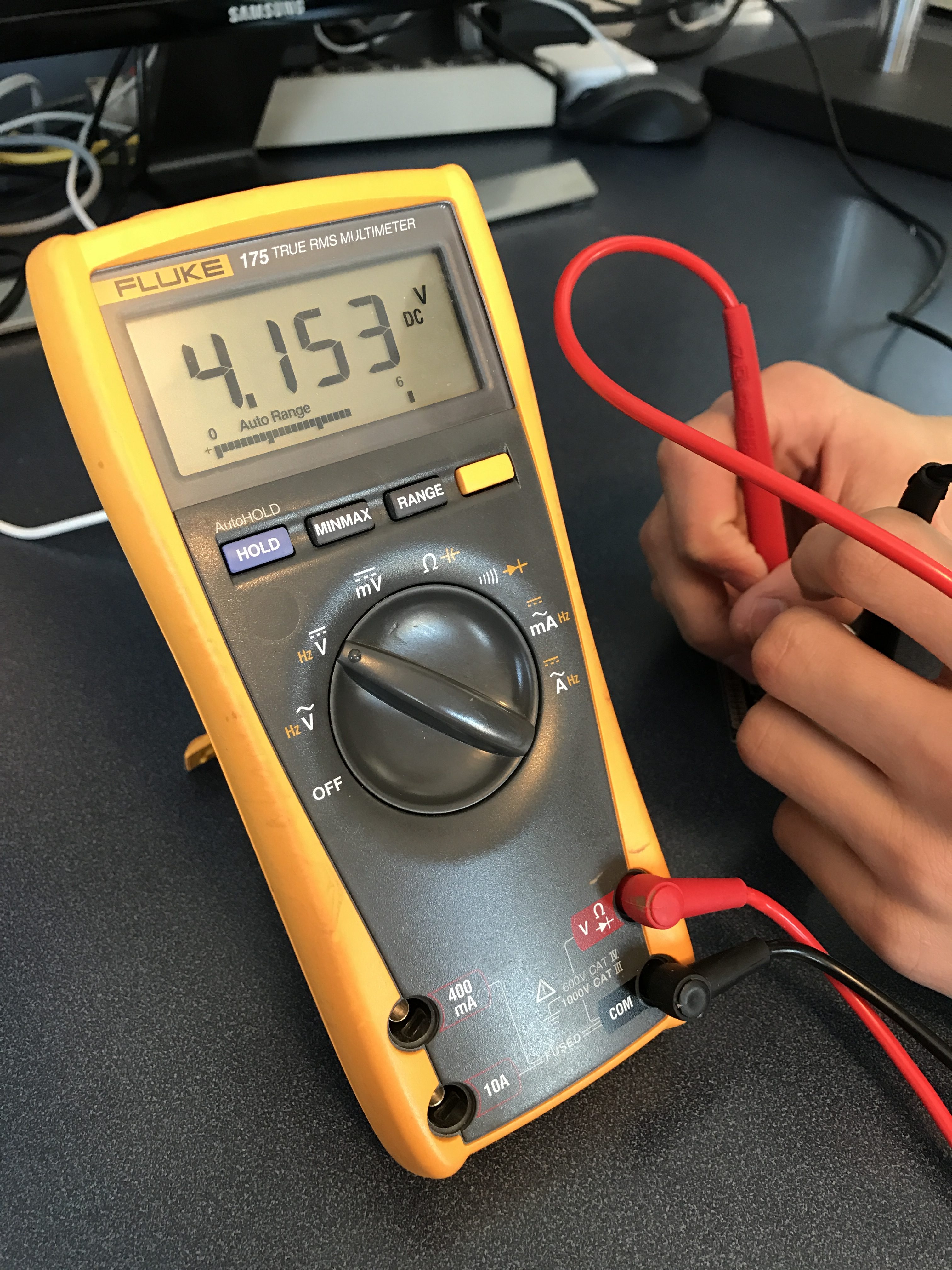
My father always says he would rather be lucky than good. I always assume that had something to do with his age. I never liked that sentiment. Actually “not like” doesn’t even begin to cover my dislike of that idea. I guess that I am always distrustful of luck. But todays post is a story of good luck. In my post about testing the PCB I showed a picture of my Fluke Meter showing 4.153V DC. That is cool, expect the power supply in my system is supposed to be regulating the power to 3.3v. I didn’t sweat the number at the time, but that is a long way from 3.3v. In fact it is enough to put 3.3V chips-like my accelertomer-at risk of blowing up. So now what?
LM317 Power LDO Power Supply
Well, on my board I used an LM317 Low Drop Out adjustable regulator. When I went to setup things up I googled and found this schematic and table of values. So that is what I put in my design.
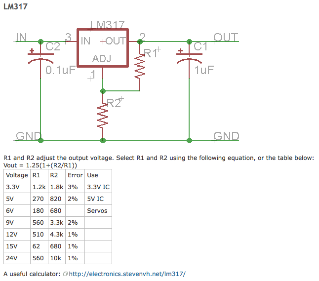
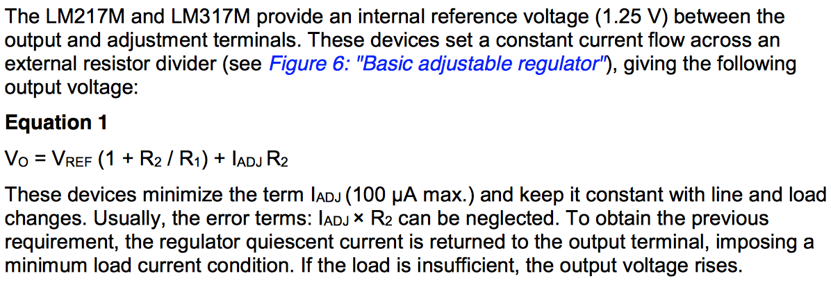
I knew that the regulator is adjustable and the feedback resistor network sets the voltage of the output. When I had the wrong voltage I assumed that I had the wrong size resistors. So I unsoldered the damn resistors and measured them. They were dead on, so I put them back on the board. This left me really wondering, so I went and looked at the datasheet for the LM317. This is what it says:
There are a bunch of LM317 calculators on the web. When I looked at them I realized that something might be really bad. Specifically the resistors from the table (R1=1.2k, R2=1.8k) were probably too large. That means that there was probably no enough current going back into regulator. So, this could be the source of my problem. As I was soldering and unsoldering I realized something really BAD. I did not put a LM317 on the board. I put a LM117 on the board. Holy shit batman! Why does that work at ALL?
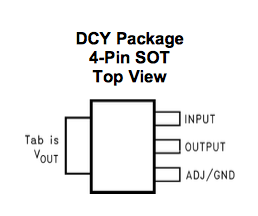
The basic answer is that the LM117 that I used was a 3.3V regulator and had the feedback resistors built in. Meaning, it wasn’t adjustable at all. I got totally totally luck as the pinout was exactly the same as the LM317 and ALL I had to do was connect the ADJ resistor to ground instead of the stack. Moreover, the “tab” was not connected to anything so the output voltage wasn’t shorted to ground either.
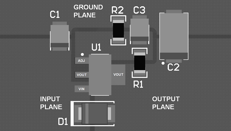
As I read the datasheet I learned something else. My layout is a long long way from optimal. Here is a picture from the datasheet.
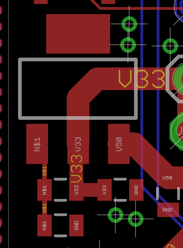
And here is my layout.
Oh well. I got lucky. Totally. I don’t like it. But there it is. When I tapeout the board again Ill fix the regulator layout.
You can find all of the source code and files at the IOTEXPERT site on github.
Index
Description
Pinball: Newton's Attic Pinball
An introduction to the project and the goals
Pinball: Lotsa Blinking LEDs
Everyone needs a bunch of LEDs on their Pinball Machine
Pinball: Matrix LEDs (Part 1)
Saving PSoC pins by using a matrix scheme
Pinball: Matrix LEDs (Part 2)
Solving some problems with the matrix
Pinball: Matrix LEDs Component
How to turn the Matrix LED into a component
Pinball: A Switch Matrix
Implementing a bunch of switches
Pinball: Switch Matrix Component (Part 1)
The switch matrix component implementation
Pinball: Switch Matrix Component (Part 2)
The firmware for matrix component
Pinball: Switch Matrix Component (Part 3)
Test firmware for the matrix component
Pinball: The Music Player (Part 1)
The schematic and symbol for a Music Player component
Pinball: The Music Player (Part 2)
The Public API for the Music Player component
Pinball: The Music Player (Part 3)
The firmware to make the sweet sweet music
Pinball: The Music Player (Part 4)
The test program for the music player
Pinball: The Motors + HBridge
Using an Bridge to control DC Motors
Pinball: The Eagle Schematic
All of the circuits into an Eagle schematic
Pinball: The Printed Circuit Board 1.0
The first Eagle PCB layout of the printed circuit board
Pinball: The PCB Version 1.0 Fail
Problems with the first version of the Eagle PCB layout
Pinball: PCB Layout 1.2 Updates using Eagle
Fixing the errors on the first two versions of the Eagle PCB
Pinball: Assemble and Reflow the 1.2 PCB
Assembling the Eagle PCB
Pinball: Testing the Eagle PCB
Firmware to test the newly built Pinball printed circuit board
Pinball: Debugging the Motor Driver
Fixing the motor driver PSoC project
Pinball: Hot-Air Reworking the Accelerometer Solder
Using a Hot-Air Rework tool to reflow a QFN
Pinball: Debugging the LM317 Power Supply- A Tale of Getting Lucky
Debugging the LM317/LM117 power supply

No comment yet, add your voice below!