Summary
Instructions to create a new Modus Toolbox / AnyCloud library including modifying your master middleware manifest and updating the dependencies. The new library and dependencies will then be available in your library browser and new project creator.
Article
(Part 1) Create Basic Project & Add Cypress Logging Functionality
(Part 2) Create New Thread to manage WiFi using the Wireless Connection Manager
(Part 3) Create a New Middleware Library with WiFi helper functions
(Part 4) Add WiFi Scan
Add WiFi Connect
Add WiFi Disconnect
Add WiFi Ping
Add Gethostbyname
Add MDNS
Add Status
Add StartAP
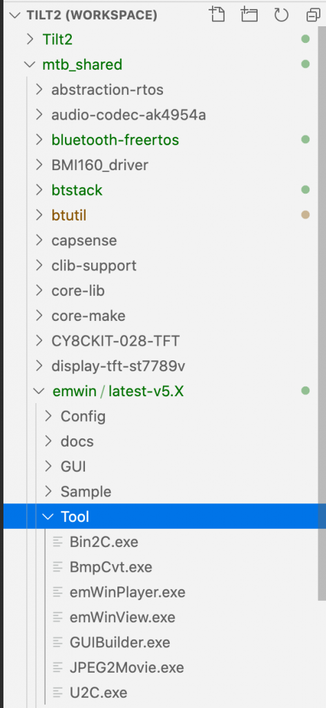
Make a new template project (update manifest)
Story
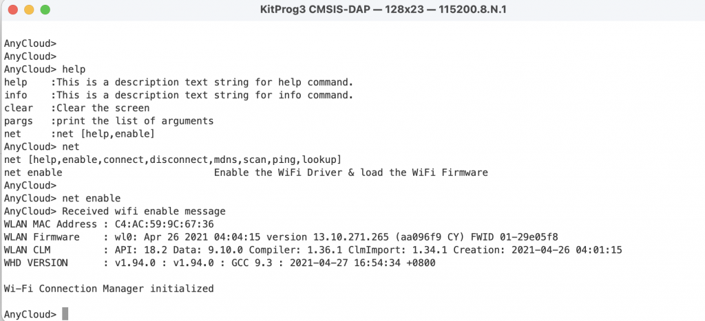
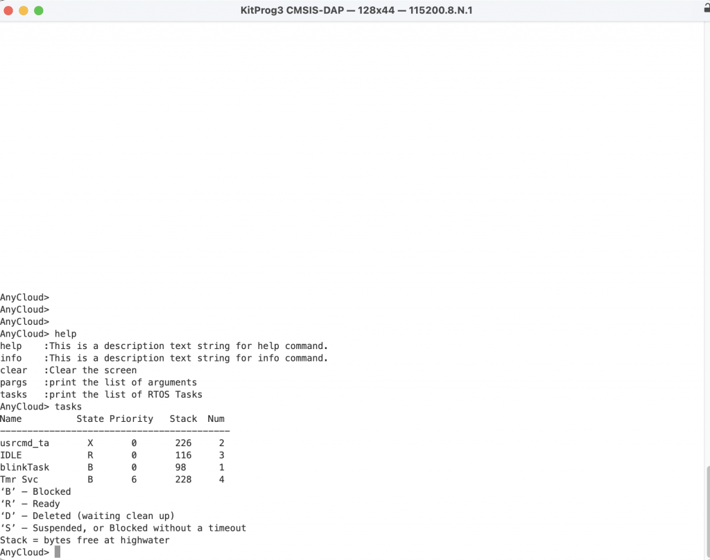
In the previous article we discussed the steps to turn on the WiFi chip in your project using the Wireless Connection Manager Anycloud (WCM) library. When something happens with the WCM it will give you a callback to tell you what happened. In my example code there were three printf’s that were commented out for the conditions:
- CY_WCM_EVENT_IP_CHANGED
- CY_WCM_EVENT_STA_JOINED_SOFTAP
- CY_WCM_EVENT_STA_LEFT_SOFTAP
The question you might have is “What is the new Ip Address”” or “What is the MAC address of the Station which joined the SoftAp?”
        case CY_WCM_EVENT_IP_CHANGED:           /**< IP address change event. This event is notified after connection, re-connection, and IP address change due to DHCP renewal. */
 //               cy_wcm_get_ip_addr(wifi_network_mode, &ip_addr, 1);
                printf("Station IP Address Changed: %s\n",wifi_ntoa(&ip_addr));
        break;
        case CY_WCM_EVENT_STA_JOINED_SOFTAP:    /**< An STA device connected to SoftAP. */
//            printf("STA Joined: %s\n",wifi_mac_to_string(event_data->sta_mac));
        break;
        case CY_WCM_EVENT_STA_LEFT_SOFTAP:      /**< An STA device disconnected from SoftAP. */
//            printf("STA Left: %s\n",wifi_mac_to_string(event_data->sta_mac));
So I wrote “standard” functions to
- Convert an IP address structure to a string (like ntoa in Linux)
- Convert a MAC address to a string
I essentially got these from the code example where they were redundantly repeatedly repeated. After tweaking them to suit my liking I wanted to put them in a library.
Make the C-Library
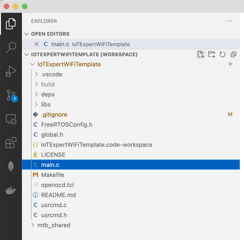
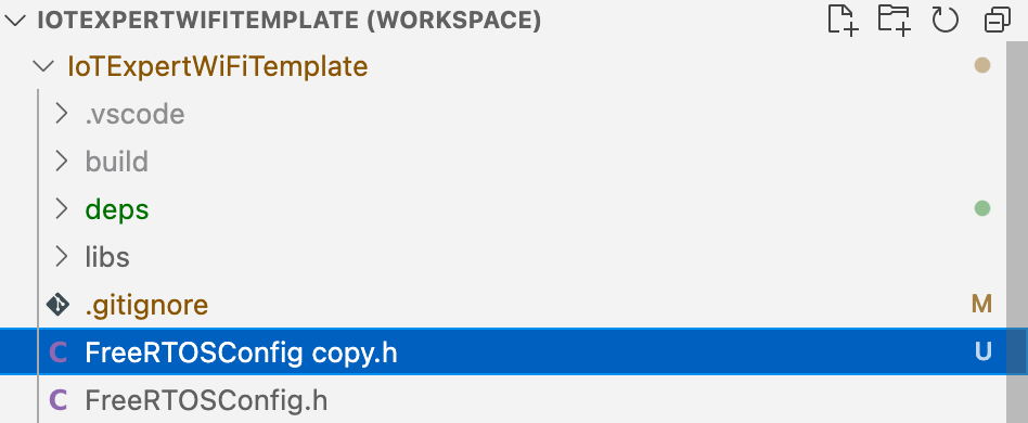
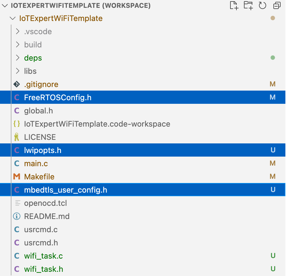
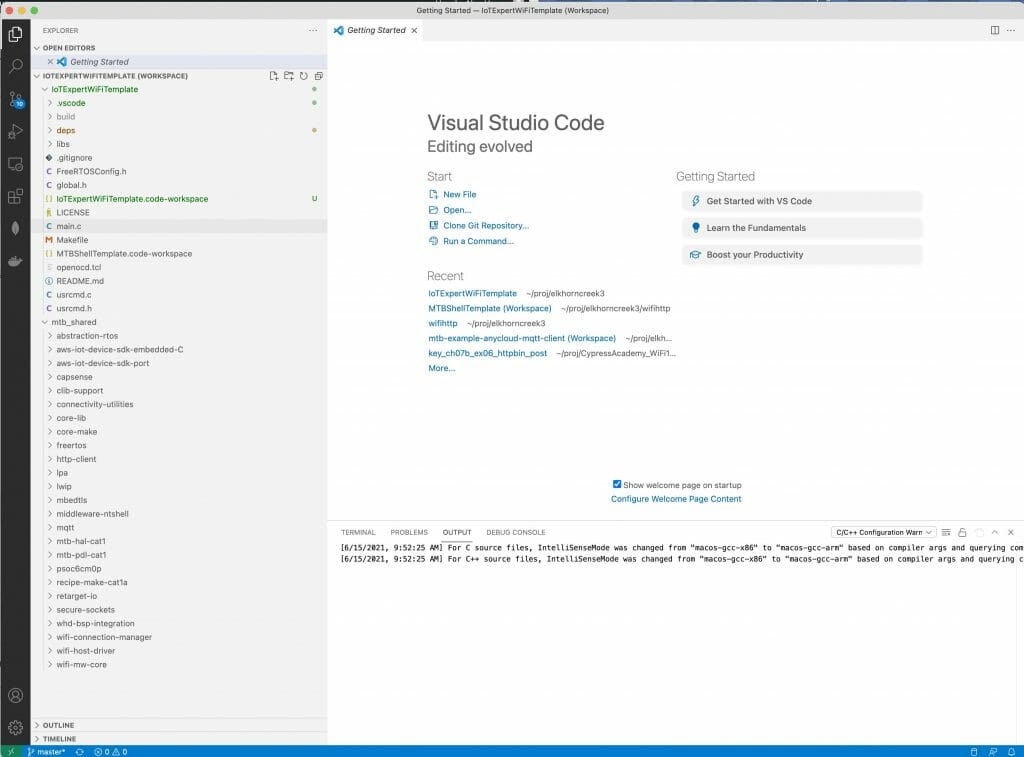
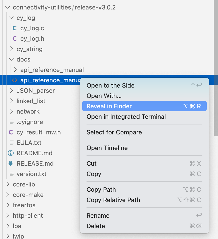
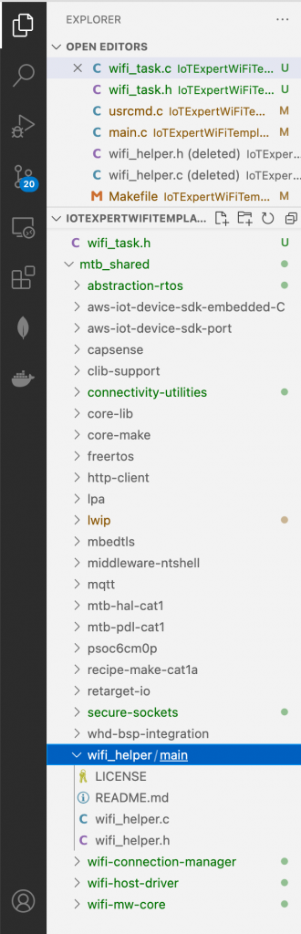
Follow these steps to make the c-library. First, make a new directory in your project called “wifi_helper”. You can do this in Visual Studio Code by pressing the folder button with the plus on it.
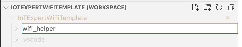
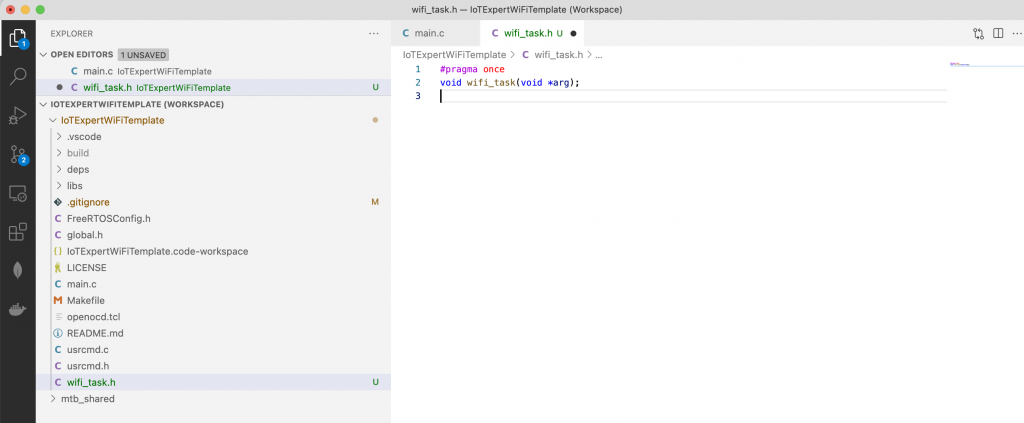
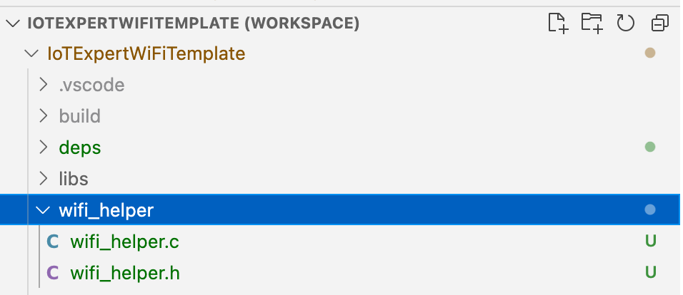
Then create the files wifi_helper.h and wifi_helper.c
In “wifi_helper.h” type in the public interface. Specifically, that we want a function that takes a mac address returns a char*. And another function that takes an IP address and returns a char*
#pragma once

#include "cy_wcm.h"

char *wifi_mac_to_string(cy_wcm_mac_t mac);

char *wifi_ntoa(cy_wcm_ip_address_t *ip_addr);
All right Hassane… yes these functions need comments. Notice that I allocated a static buffer inside of these two function. That means that these functions are NOT NOT NOT thread safe. However, personally I think that is fine as I think that it is unlikely that they would ever be called from multiple threads.
#include "wifi_helper.h"
#include "cy_wcm.h"
#include <stdio.h>
#include "cy_utils.h"
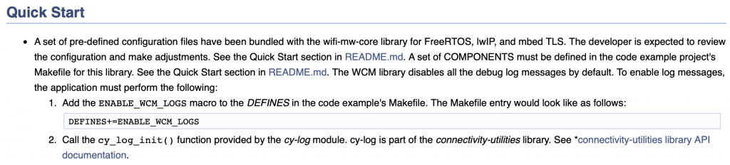
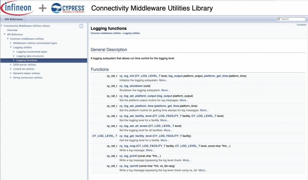
#include "cy_log.h"
char *wifi_mac_to_string(cy_wcm_mac_t mac)
{
static char _mac_string[] = "xx:xx:xx:xx:xx:xx";
sprintf(_mac_string,"%02X:%02X:%02X:%02X:%02X:%02X",mac[0],mac[1],mac[2],mac[3],mac[4],mac[5]);
return _mac_string;
}
char *wifi_ntoa(cy_wcm_ip_address_t *ip_addr)
{
static char _netchar[32];
switch(ip_addr->version)
{
case CY_WCM_IP_VER_V4:
sprintf(_netchar,"%d.%d.%d.%d", (uint8_t)ip_addr->ip.v4,
(uint8_t)(ip_addr->ip.v4 >> 8), (uint8_t)(ip_addr->ip.v4 >> 16),
(uint8_t)(ip_addr->ip.v4 >> 24)); break;
case CY_WCM_IP_VER_V6:
sprintf(_netchar,"%X:%X:%X:%X", (uint8_t)ip_addr->ip.v6[0],
(uint8_t)(ip_addr->ip.v6[1]), (uint8_t)(ip_addr->ip.v6[2]),
(uint8_t)(ip_addr->ip.v6[3]));
break;
}
CY_ASSERT(buff[0] != 0); // SOMETHING should have happened
return _netchar;
}
Git Repository
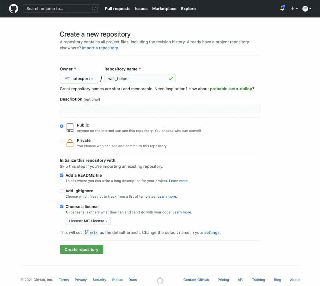
Now that I have the files I need in the library, I want to create a place on GitHub to hold the library.
Now we need to integrate the files into Git. To do this you need to
- Initialize a new git repository (git init .)
- Add a remote (git remote add origin git@github.com:iotexpert/wifi_helper.git)
- Pull the remote files (README and LICENSE) with (git pull origin main)
- Add the wifi_helper files (git add wifi_helper.*)
- Commit the changes (git commit -m “added initial c files”)
- Push them to the remote (git push -u origin main)
arh (master *+) wifi_helper $ pwd
/Users/arh/proj/elkhorncreek3/IoTExpertWiFiTemplate/wifi_helper
arh (master *+) wifi_helper $ git init .
Initialized empty Git repository in /Users/arh/proj/elkhorncreek3/IoTExpertWiFiTemplate/wifi_helper/.git/
arh (main #) wifi_helper $ git remote add origin git@github.com:iotexpert/wifi_helper.git
arh (main #) wifi_helper $ git pull origin main
remote: Enumerating objects: 4, done.
remote: Counting objects: 100% (4/4), done.
remote: Compressing objects: 100% (4/4), done.
remote: Total 4 (delta 0), reused 0 (delta 0), pack-reused 0
Unpacking objects: 100% (4/4), 1.28 KiB | 436.00 KiB/s, done.
From iotexpert.github.com:iotexpert/wifi_helper
 * branch            main       -> FETCH_HEAD
 * [new branch]      main       -> origin/main
arh (main) wifi_helper $ git add wifi_helper.*
arh (main +) wifi_helper $ git commit -m "added initial c files"
[main f7d10b1] added initial c files
 2 files changed, 72 insertions(+)
 create mode 100644 wifi_helper.c
 create mode 100644 wifi_helper.h
arh (main) wifi_helper $ git push -u origin main
Enumerating objects: 5, done.
Counting objects: 100% (5/5), done.
Delta compression using up to 12 threads
Compressing objects: 100% (4/4), done.
Writing objects: 100% (4/4), 1.10 KiB | 1.10 MiB/s, done.
Total 4 (delta 0), reused 0 (delta 0), pack-reused 0
To iotexpert.github.com:iotexpert/wifi_helper.git
   3a1ad32..f7d10b1  main -> main
Branch 'main' set up to track remote branch 'main' from 'origin'.
arh (main) wifi_helper $
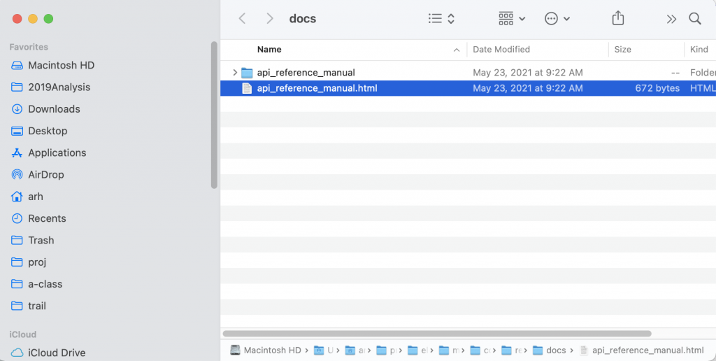
Now you will have something like this on GitHub.
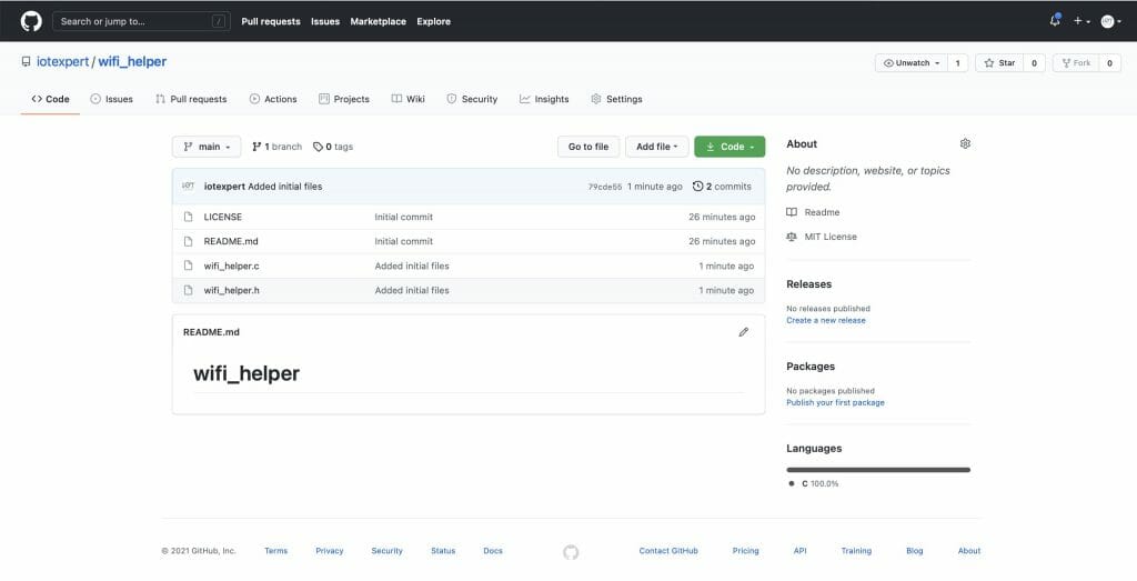
Manifest Files
I would like to be able to have my new library show up in the library browser. But how? When the library browser starts up it needs to discover:
- Board Support Packages
- Template Projects
- Middleware Code Libraries
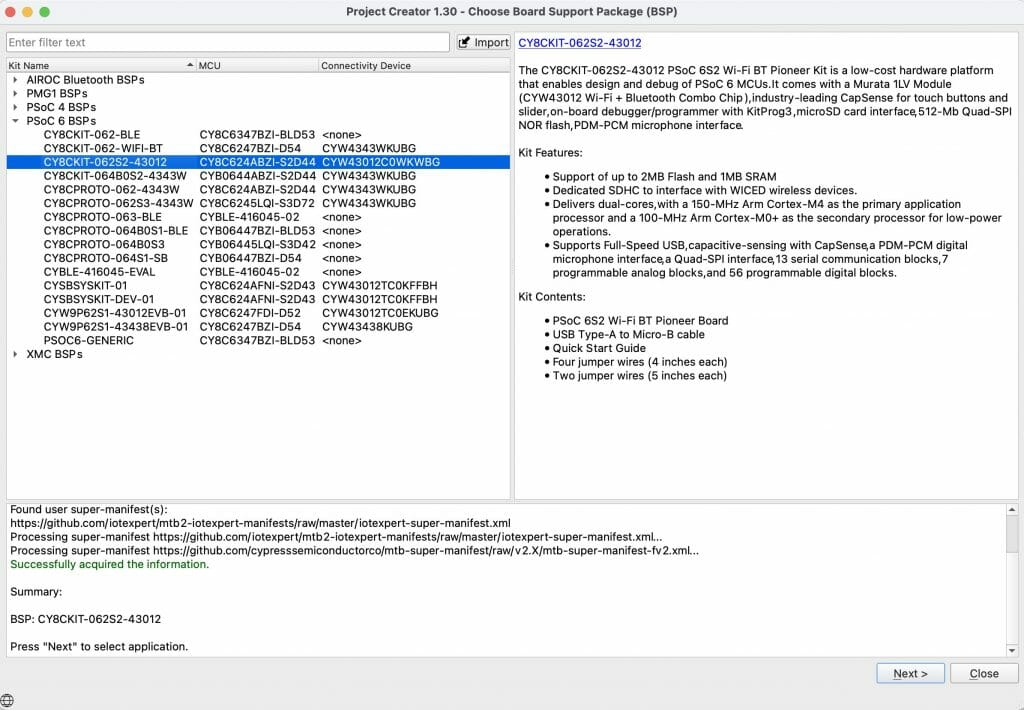
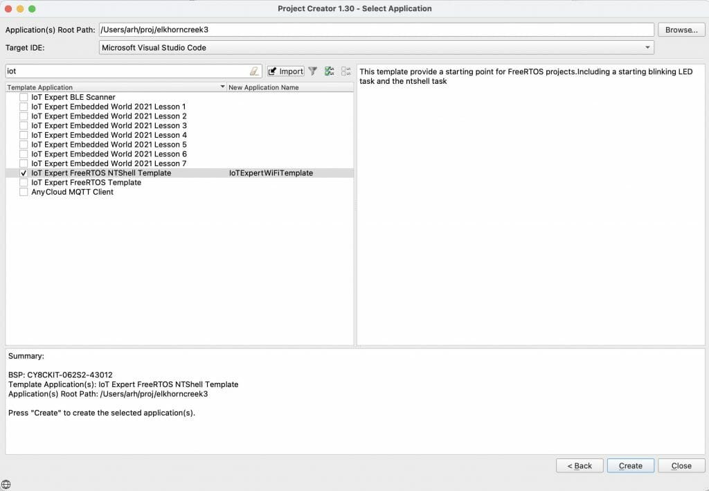
To do this, it reads a series of XML files called “manifests”. These manifest files tell the library browser where to find the libraries. If you have ever noticed the library browser (or the new project creator) it looks like this:
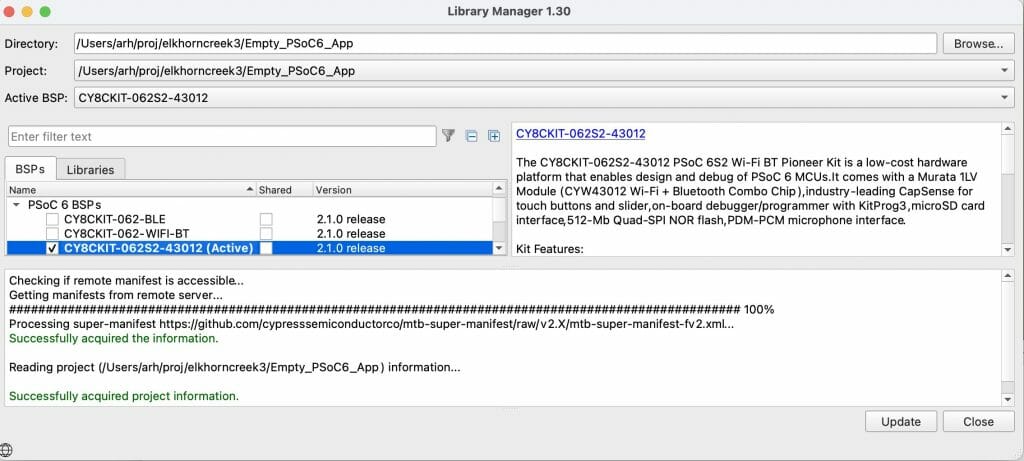
The message “Processing super-manifest …” give you a hint to go to https://raw.githubusercontent.com/cypresssemiconductorco/mtb-super-manifest/v2.X/mtb-super-manifest-fv2.xml
Here it is. Notice that the XML scheme says that this file is a “super-manifest”. Then notice that there are sections:
- <board-manifest-list> these are BSPs
- <app-manifest-list> these are template projects
- <middleware-manifest-list> these are middleware code libraries
<super-manifest>
  <board-manifest-list>
    <board-manifest>
      <uri>https://github.com/cypresssemiconductorco/mtb-bsp-manifest/raw/v2.X/mtb-bsp-manifest.xml</uri>
    </board-manifest>
    <board-manifest dependency-url="https://github.com/cypresssemiconductorco/mtb-bsp-manifest/raw/v2.X/mtb-bsp-dependencies-manifest.xml">
      <uri>https://github.com/cypresssemiconductorco/mtb-bsp-manifest/raw/v2.X/mtb-bsp-manifest-fv2.xml</uri>
    </board-manifest>
    <board-manifest>
      <uri>https://github.com/cypresssemiconductorco/mtb-bt-bsp-manifest/raw/v2.X/mtb-bt-bsp-manifest.xml</uri>
    </board-manifest>
    <board-manifest dependency-url="https://github.com/cypresssemiconductorco/mtb-bt-bsp-manifest/raw/v2.X/mtb-bt-bsp-dependencies-manifest.xml">
      <uri>https://github.com/cypresssemiconductorco/mtb-bt-bsp-manifest/raw/v2.X/mtb-bt-bsp-manifest-fv2.xml</uri>
    </board-manifest>
  </board-manifest-list>
  <app-manifest-list>
    <app-manifest>
      <uri>https://github.com/cypresssemiconductorco/mtb-ce-manifest/raw/v2.X/mtb-ce-manifest.xml</uri>
    </app-manifest>
    <app-manifest>
      <uri>https://github.com/cypresssemiconductorco/mtb-ce-manifest/raw/v2.X/mtb-ce-manifest-fv2.xml</uri>
    </app-manifest>
    <app-manifest>
      <uri>https://github.com/cypresssemiconductorco/mtb-bt-app-manifest/raw/v2.X/mtb-bt-app-manifest.xml</uri>
    </app-manifest>
    <app-manifest>
      <uri>https://github.com/cypresssemiconductorco/mtb-bt-app-manifest/raw/v2.X/mtb-bt-app-manifest-fv2.xml</uri>
    </app-manifest>
  </app-manifest-list>
  <middleware-manifest-list>
    <middleware-manifest>
      <uri>https://github.com/cypresssemiconductorco/mtb-mw-manifest/raw/v2.X/mtb-mw-manifest.xml</uri>
    </middleware-manifest>
    <middleware-manifest dependency-url="https://github.com/cypresssemiconductorco/mtb-mw-manifest/raw/v2.X/mtb-mw-dependencies-manifest.xml">
      <uri>https://github.com/cypresssemiconductorco/mtb-mw-manifest/raw/v2.X/mtb-mw-manifest-fv2.xml</uri>
    </middleware-manifest>
    <middleware-manifest>
      <uri>https://github.com/cypresssemiconductorco/mtb-bt-mw-manifest/raw/v2.X/mtb-bt-mw-manifest.xml</uri>
    </middleware-manifest>
    <middleware-manifest dependency-url="https://github.com/cypresssemiconductorco/mtb-bt-mw-manifest/raw/v2.X/mtb-bt-mw-dependencies-manifest.xml">
      <uri>https://github.com/cypresssemiconductorco/mtb-bt-mw-manifest/raw/v2.X/mtb-bt-mw-manifest-fv2.xml</uri>
    </middleware-manifest>
    <middleware-manifest>
      <uri>https://github.com/cypresssemiconductorco/mtb-wifi-mw-manifest/raw/v2.X/mtb-wifi-mw-manifest.xml</uri>
    </middleware-manifest>
    <middleware-manifest dependency-url="https://github.com/cypresssemiconductorco/mtb-wifi-mw-manifest/raw/v2.X/mtb-wifi-mw-dependencies-manifest.xml">
      <uri>https://github.com/cypresssemiconductorco/mtb-wifi-mw-manifest/raw/v2.X/mtb-wifi-mw-manifest-fv2.xml</uri>
    </middleware-manifest>
  </middleware-manifest-list>
</super-manifest>
But you can’t modify this to add your own? So what do you do now? Cypress put in the capability for you to extend the system by creating a file called “~/.modustoolbox/manifest.loc”. This file contains one or more URLs to super-manifest files (like the one above) where you can add whatever you want.
Here is the iotexpert manifest.loc
arh ~ $ cd ~/.modustoolbox/
arh .modustoolbox $ more manifest.loc
https://github.com/iotexpert/mtb2-iotexpert-manifests/raw/master/iotexpert-super-manifest.xml
arh .modustoolbox $
This file points to a super manifest file in a GitHub repository. Here is the repository:
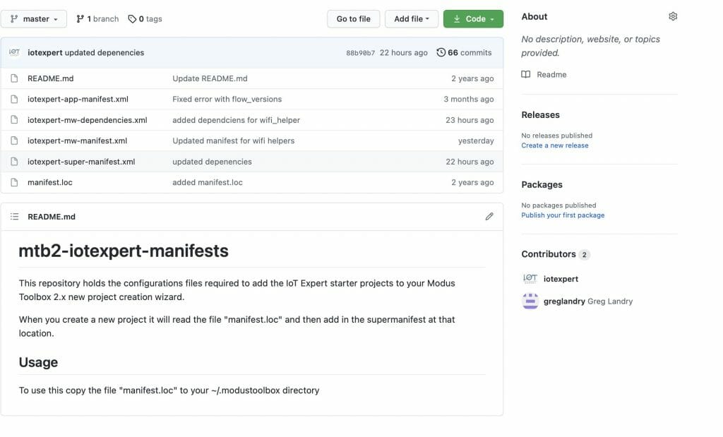
Notice that it has
- iotexpert-super-manifest.xml – the top level iotexpert manifest
- iotexpert-app-manifest.xml – my template projects
- iotexpert-mw-manifest.xml – my middleware
- manifest.loc – the file you need to put in your home directory
- iotexpert-mw-dependencies.xml – a new file which I will talk about later
And the super manifest file that looks like this:
<super-manifest>
  <board-manifest-list>
  </board-manifest-list>

  <app-manifest-list>
    <app-manifest>
      <uri>https://github.com/iotexpert/mtb2-iotexpert-manifests/raw/master/iotexpert-app-manifest.xml</uri>
      </app-manifest>
   </app-manifest-list>
  <board-manifest-list>
  </board-manifest-list>
  <middleware-manifest-list>
    <middleware-manifest dependency-url="https://github.com/iotexpert/mtb2-iotexpert-manifests/raw/master/iotexpert-mw-dependencies.xml">
      <uri>https://github.com/iotexpert/mtb2-iotexpert-manifests/raw/master/iotexpert-mw-manifest.xml</uri>
    </middleware-manifest>
  </middleware-manifest-list>
</super-manifest>
To add the library we created above, I need to add the new middleware into my middleware manifest. Modify the file “iotexpert-mw-manifest.xml” to have the new middleware.
<middleware>
  <name>WiFi Helper Utilties</name>
  <id>wifi_helper</id>
  <uri>https://github.com/iotexpert/wifi_helper</uri>
  <desc>A library WiFi Helper utilities (e.g. aton)</desc>
  <category>IoT Expert</category>
  <req_capabilities>psoc6</req_capabilities>
  <versions>
    <version flow_version="2.0">
      <num>main</num>
      <commit>main</commit>
      <desc>main</desc>
    </version>
  </versions>
</middleware>
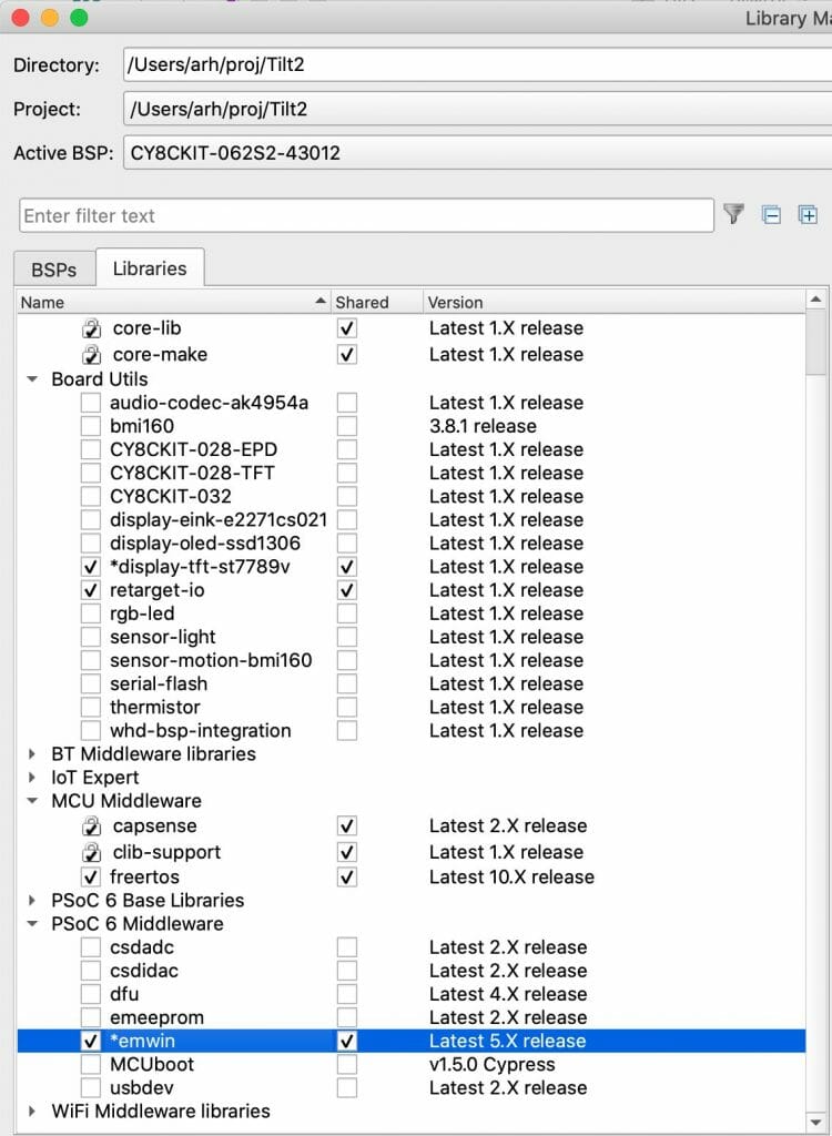
If you recall I have the “wifi_helper” directory inside of my project. Not what I want (because I want it to be pulled using the library browser). So I move out my project directory. Now, let’s test the whole thing by running the library browser.
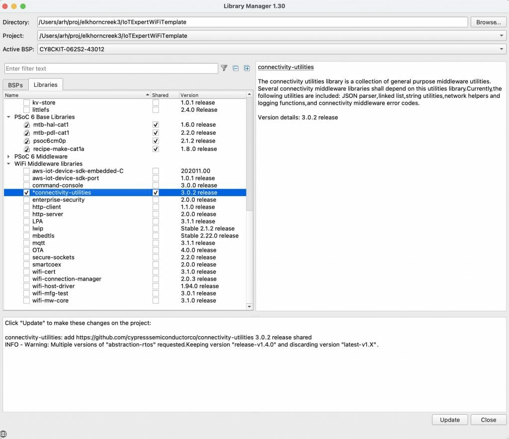
arh (master *+) IoTExpertWiFiTemplate $ pwd
/Users/arh/proj/elkhorncreek3/IoTExpertWiFiTemplate
arh (master *+) IoTExpertWiFiTemplate $ mv wifi_helper/ ~/proj/
arh (master *+) IoTExpertWiFiTemplate $ make modlibs
Tools Directory: /Applications/ModusToolbox/tools_2.3
CY8CKIT-062S2-43012.mk: ./libs/TARGET_CY8CKIT-062S2-43012/CY8CKIT-062S2-43012.mk
Launching library-manager
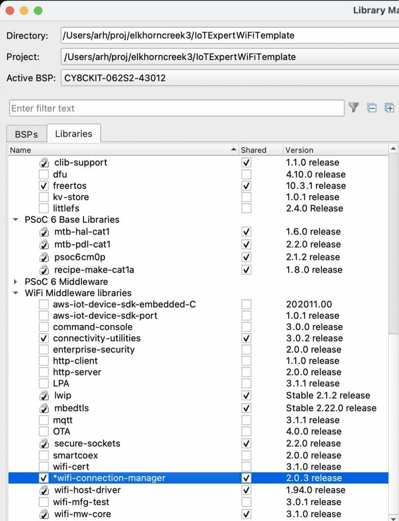
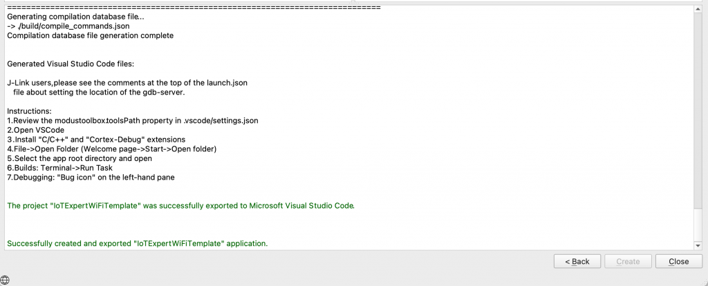
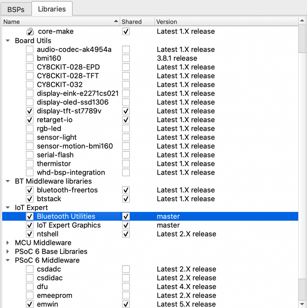
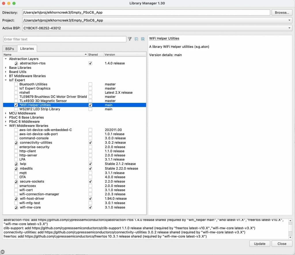
Excellent the WiFI Helper utilities show up.
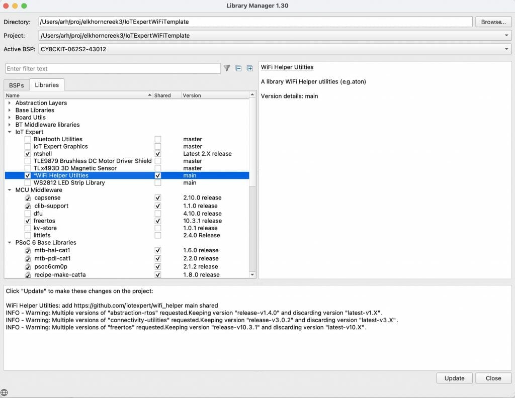
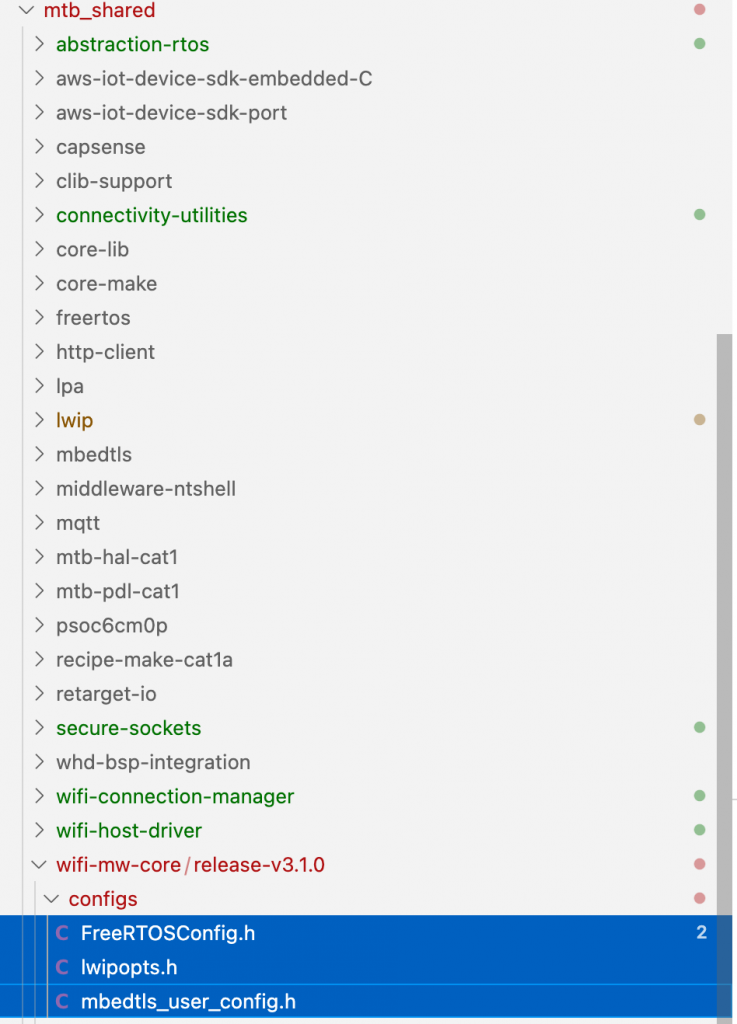
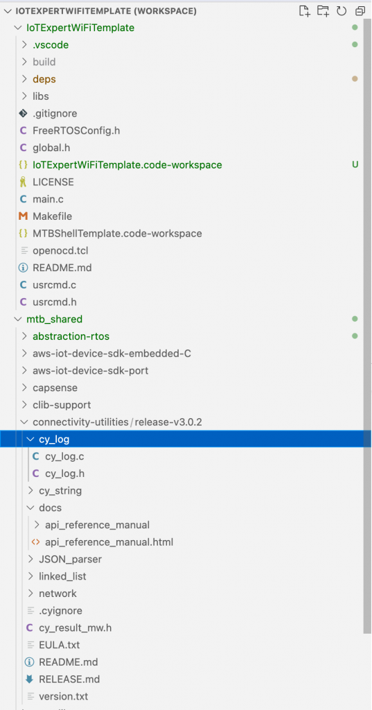
And when I run the “update” the files show up in the project.
Add Dependencies
If you recall from the code I had this include:
#include "cy_wcm.h"
That means that I am dependent on the library “wifi-connection-manager”. To make this work I create a new file called “iotexpert-mw-depenencies.xml”. In that file I tell the system that “wifi_helper” is now dependent on “wcm”
<dependencies version="2.0">
  <depender>
    <id>wifi_helper</id>
    <versions>
      <version>
        <commit>main</commit>
        <dependees>
          <dependee>
            <id>wcm</id>
            <commit>latest-v2.X</commit>
          </dependee>
        </dependees>
      </version>
    </versions>
  </depender>
</dependencies>
Once I have that file, I add that depencency file to my middleware manifest file.
  <middleware-manifest-list>
    <middleware-manifest dependency-url="https://github.com/iotexpert/mtb2-iotexpert-manifests/raw/master/iotexpert-mw-dependencies.xml">
      <uri>https://github.com/iotexpert/mtb2-iotexpert-manifests/raw/master/iotexpert-mw-manifest.xml</uri>
    </middleware-manifest>
  </middleware-manifest-list>
</super-manifest>
Now when I start the library browser and add the “WiFi Help Utilities” it will automatically add the wireless connection manager (and all of the libraries that the wcm is dependent on.
In the next article I will add Scanning functionality to the WiFi Task.