The last few weeks I have been building up the java programs that form the “back office” part of my system. This is composed of
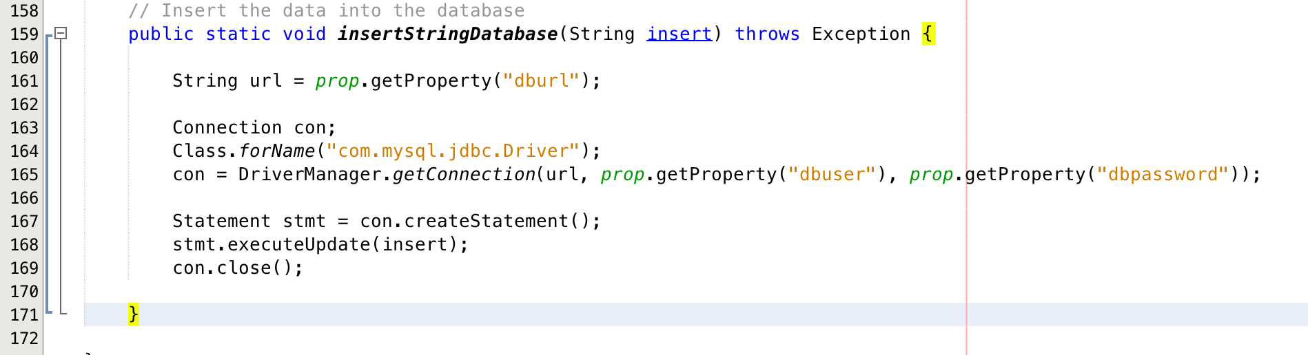
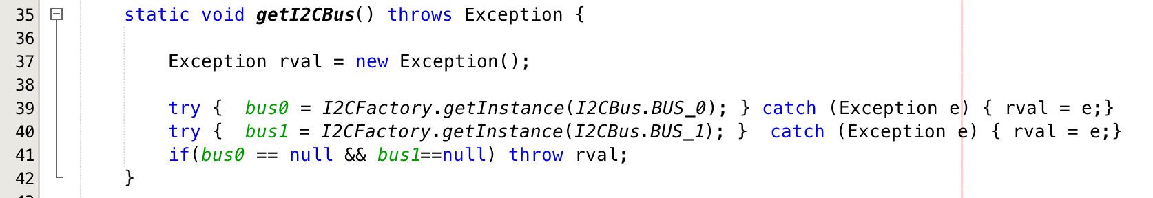
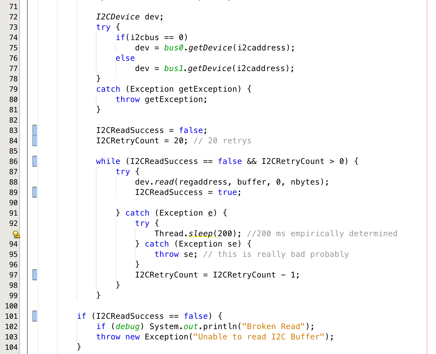
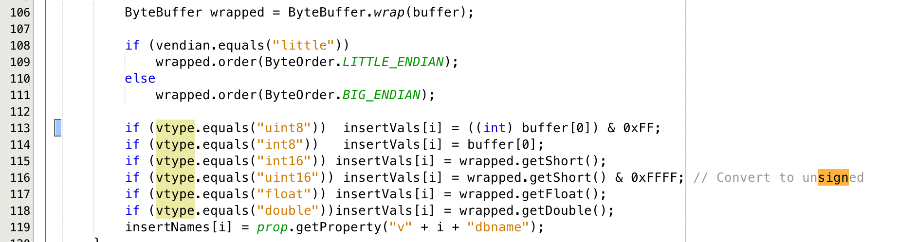
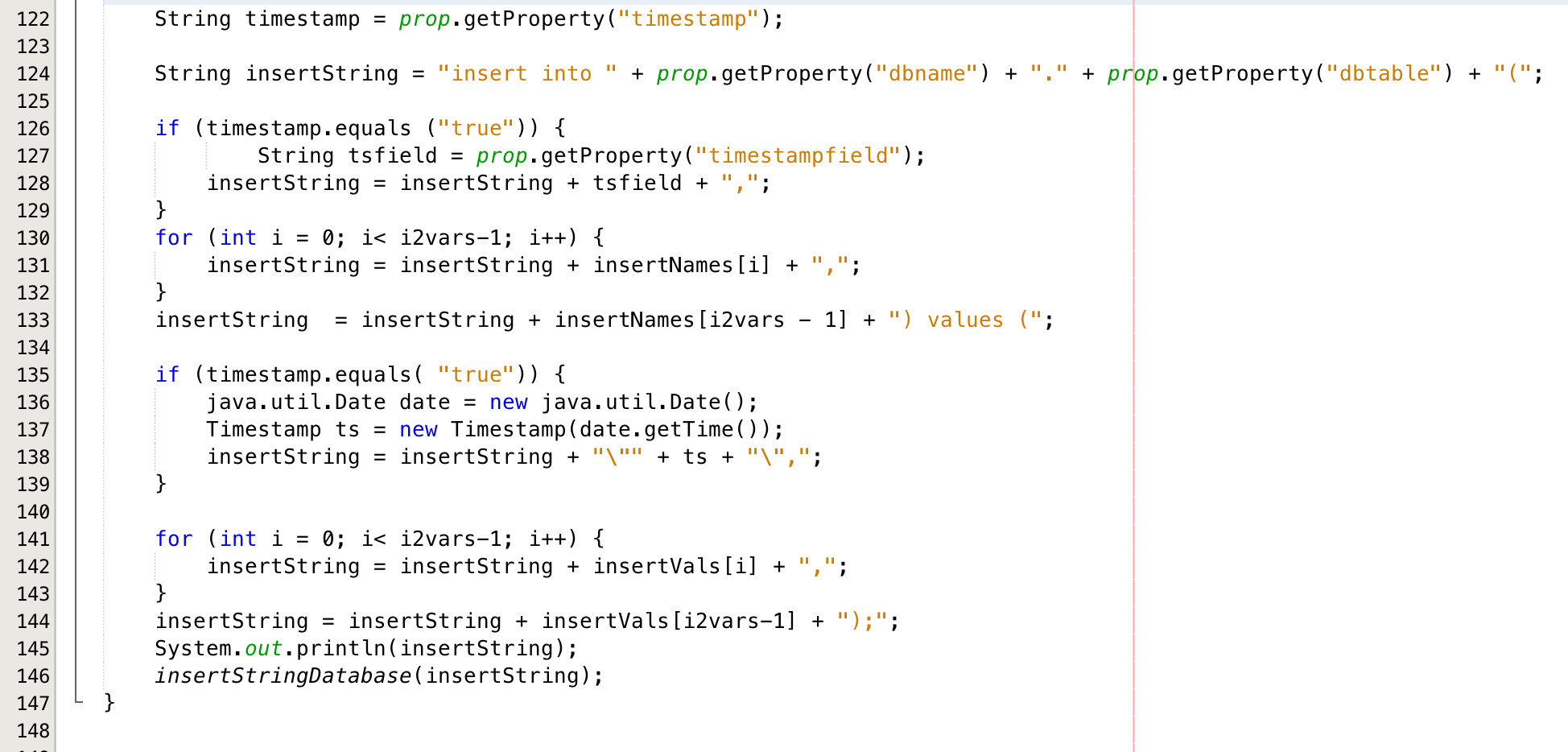
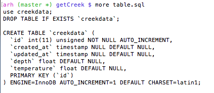
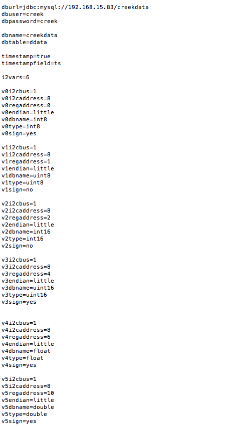
- i2cb.java: A program that reads I2C registers of the Creek Depth and Temperature and inserts them into the creekdata database.
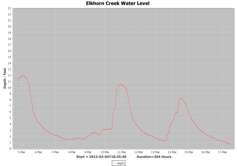
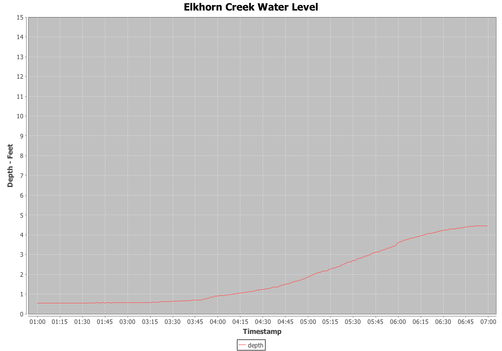
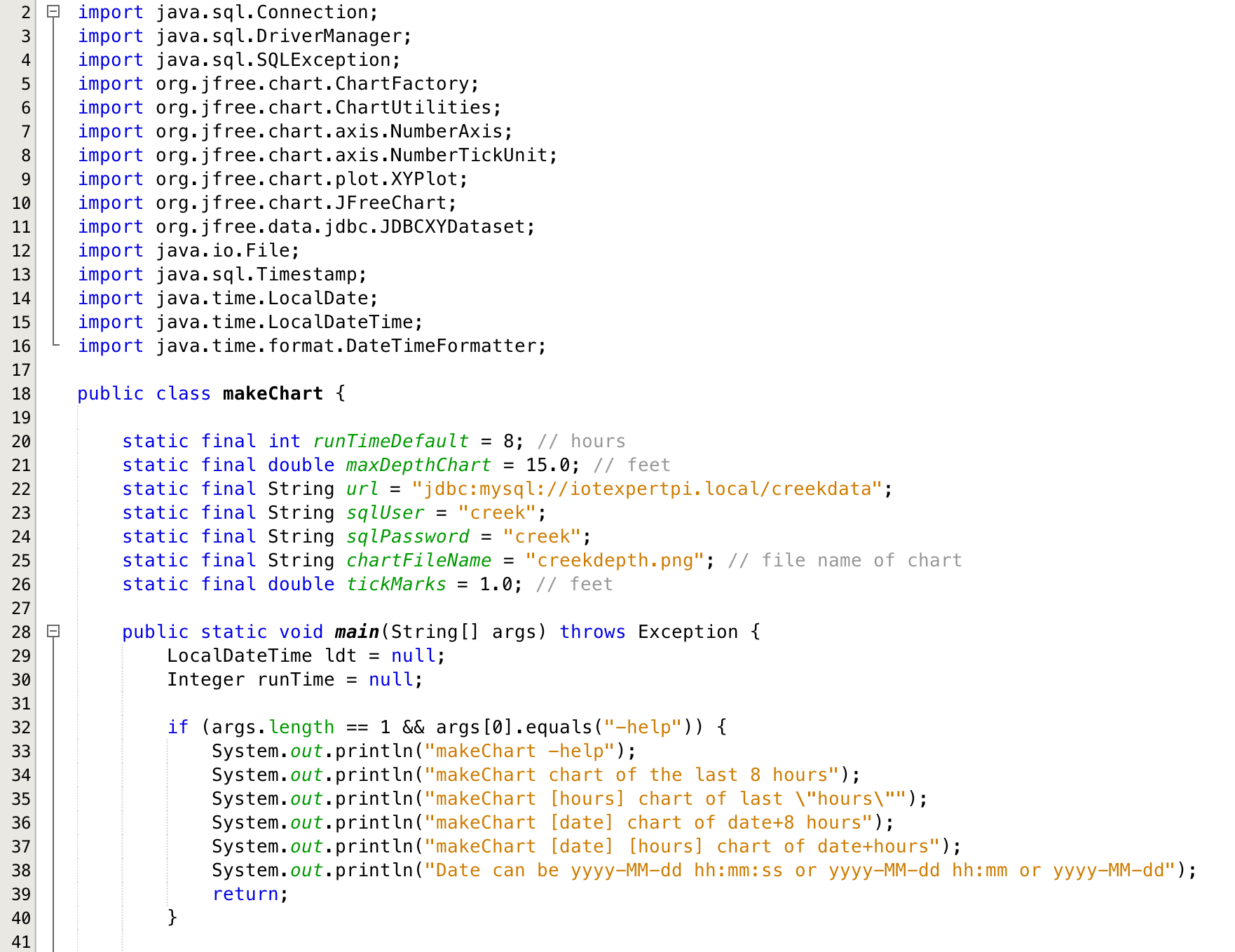
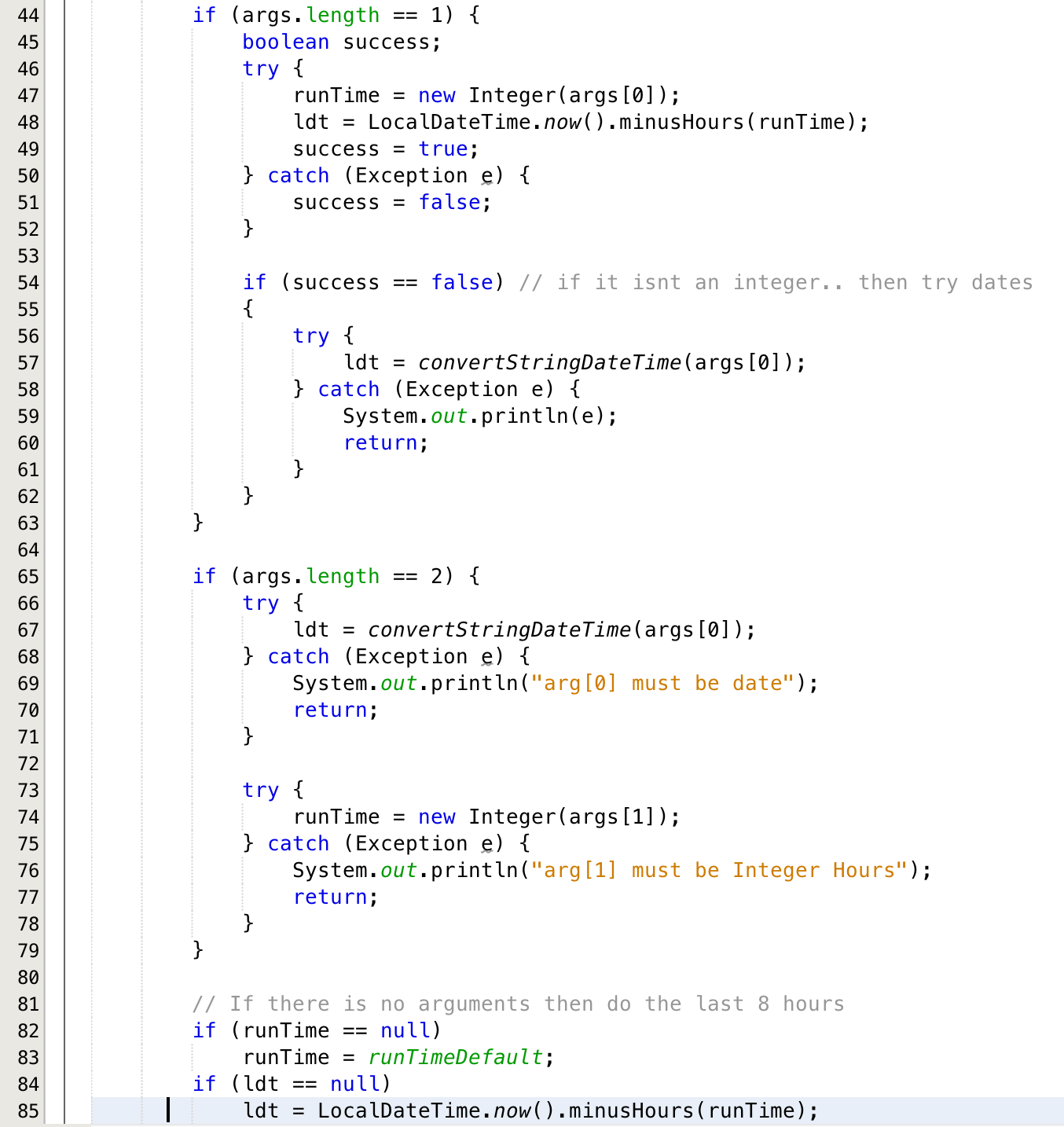
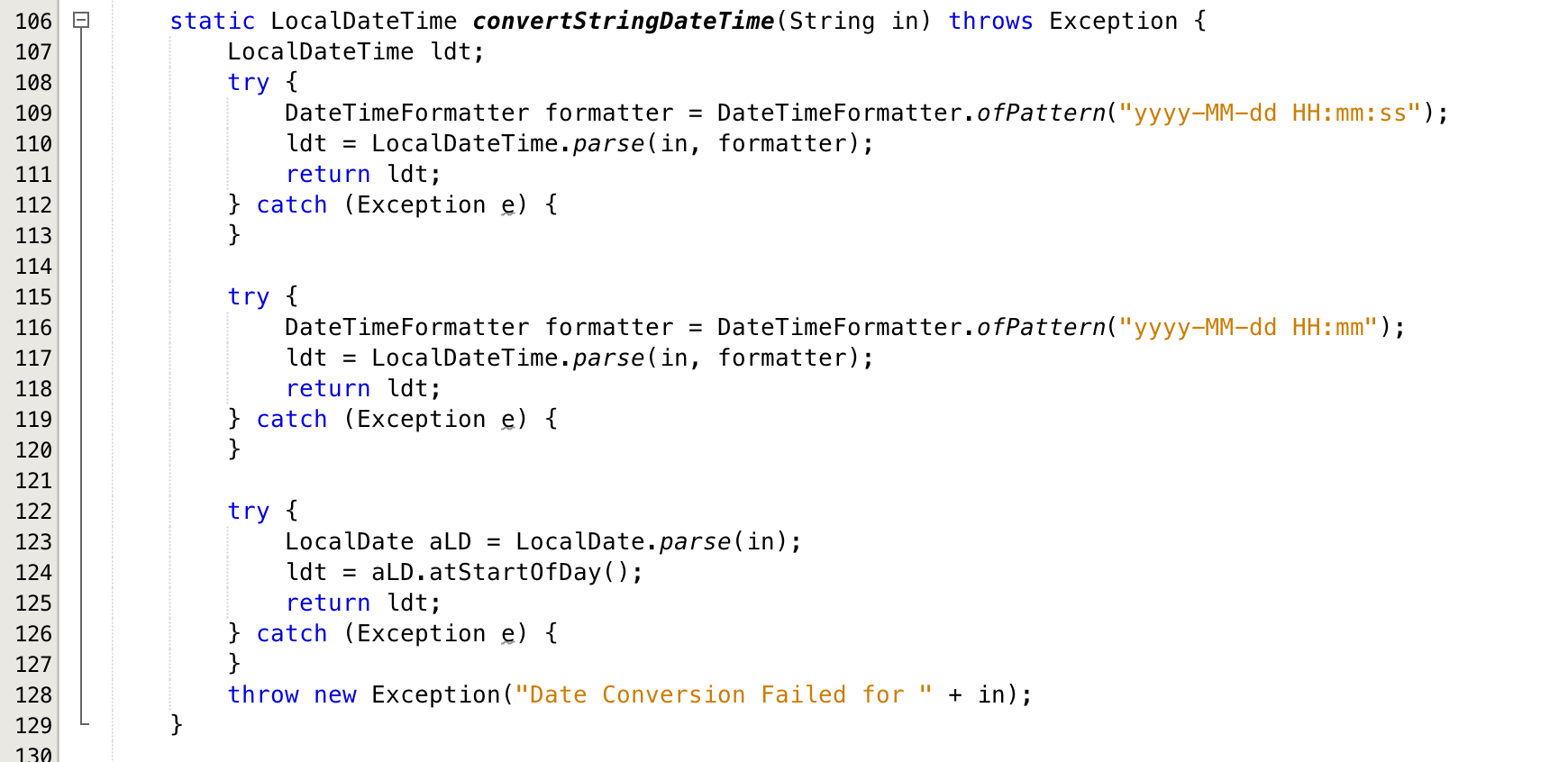
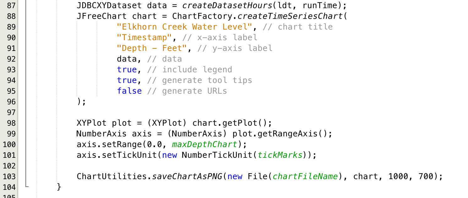
- MakeChart.java: A program to create a PNG graph of Elkhorn Creek depth using JFreeChart
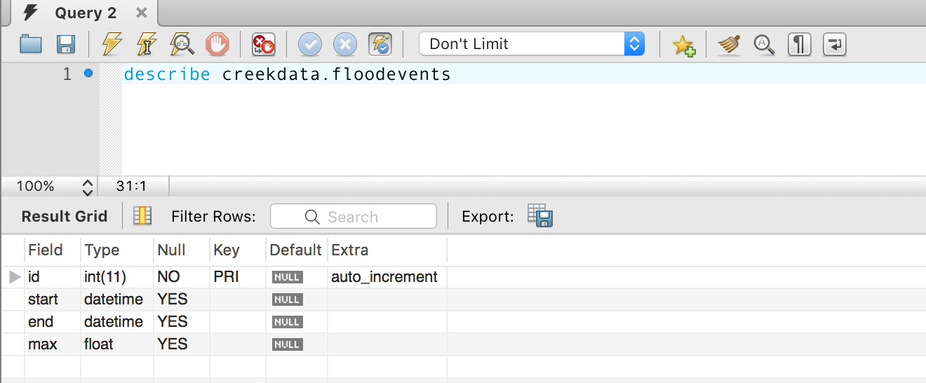
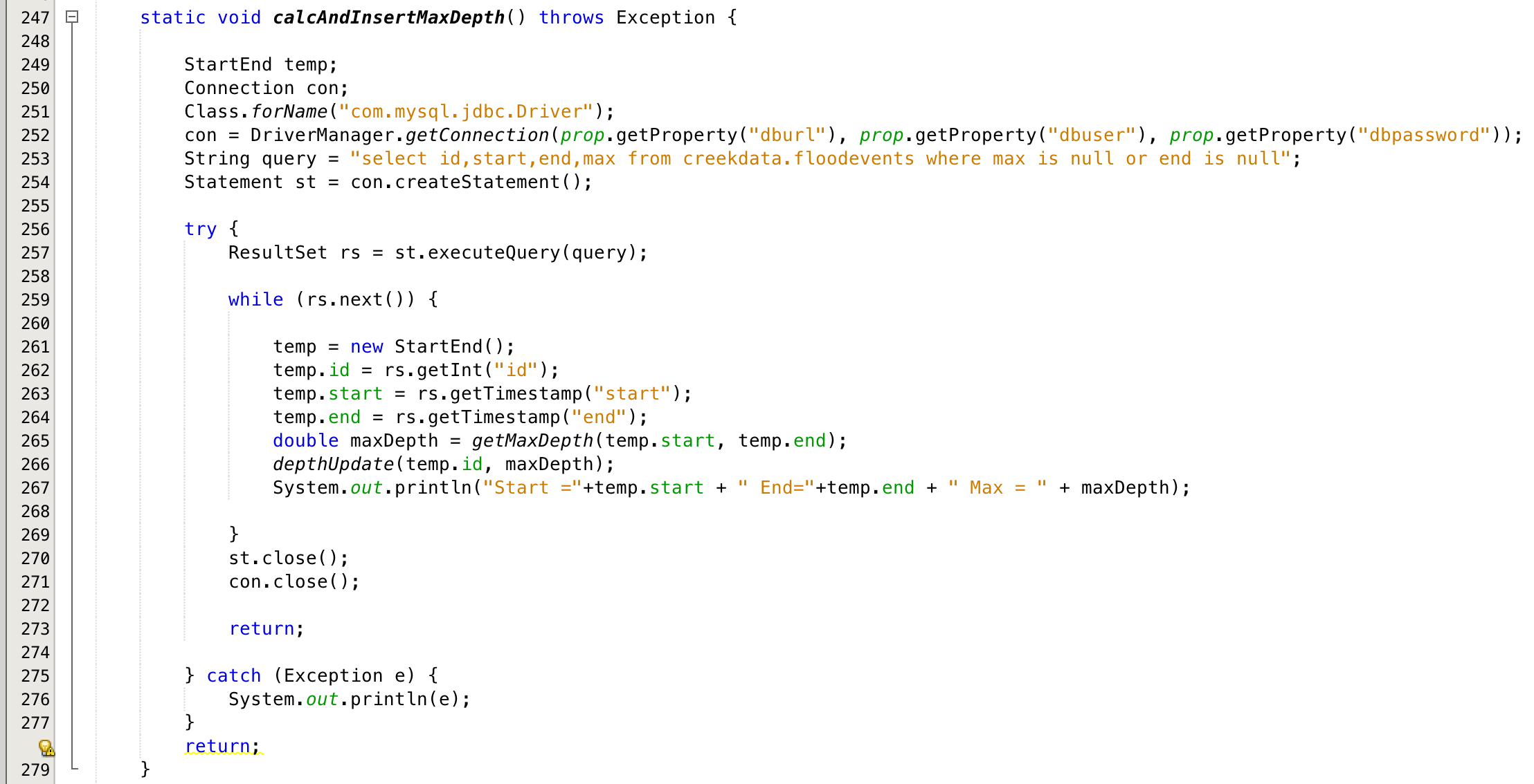
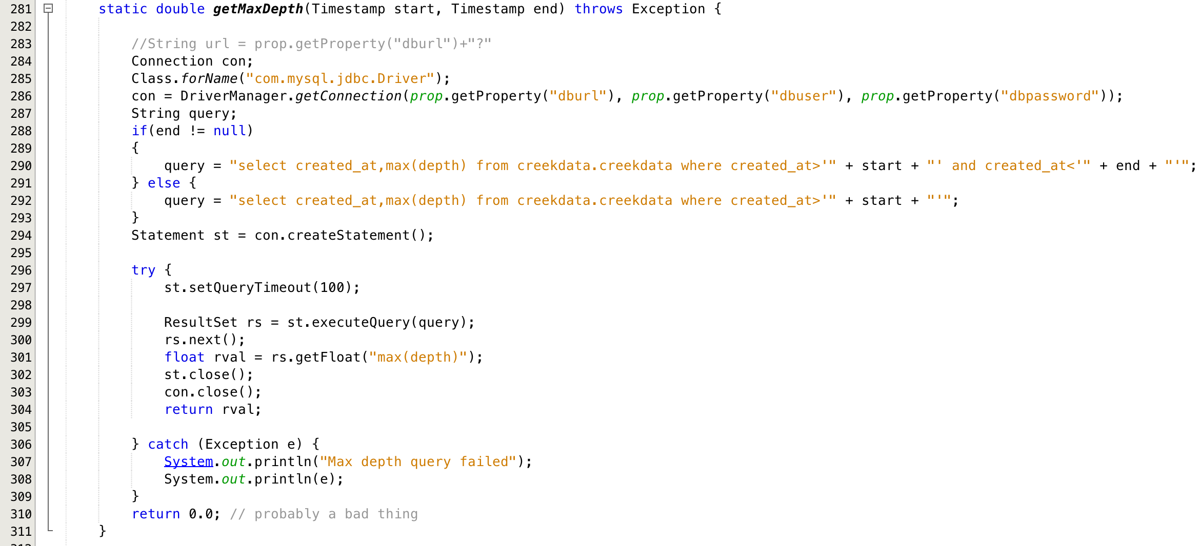
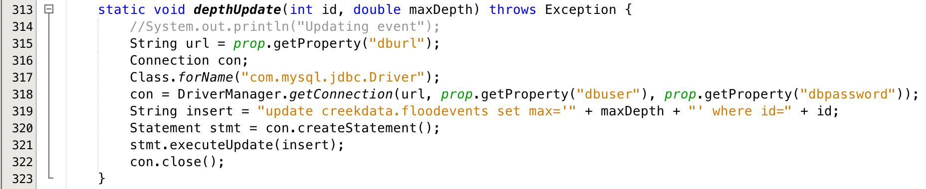
- ProcessEvents.java: A program that searches the creekdata for “flooding events” and then inserts them into the flood event database.
Things worked OK, but I had several problems that I wanted to fix
- The MakeChart program was not using global properties file so I had duplicated things like the database password
- I had implemented myself into a design flaw (I wanted to chain information from i2cdb –> MakeChart –> ProcessEvents –> MakeChart
- I really wanted a single Java program with options to run all of the back office
The bottom line is this week will be spent fixing the design flaws and cleaning up the code.
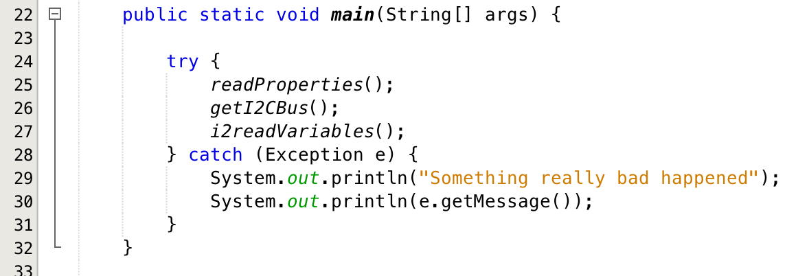
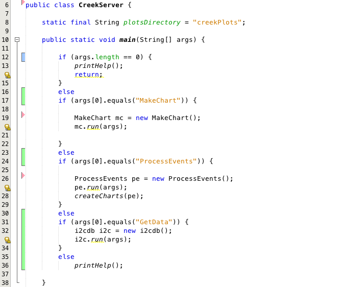
The first thing that I did was create a new Java program called “CreekServer” which hooks all of the programs together and provides a unified command line interface. This program looks at the first command line argument and decides to either:
- Lines 12-15: print the help text
- Lines 17-23: run the “MakeChart” function
- Lines 24-29: run the ProcessEvents function, then update/create all of the historical flood charts [line 27]
- Lines 30-34: run the GetData function
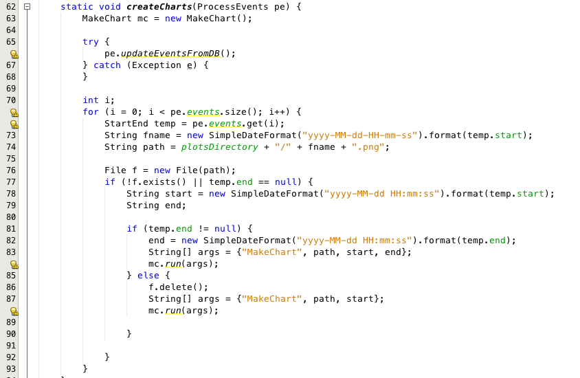
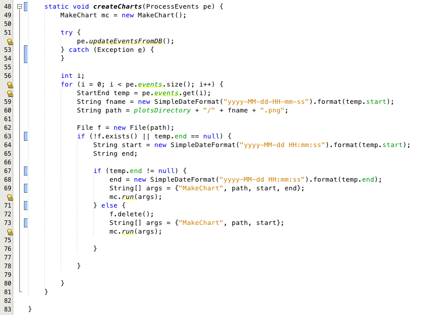
The next block of code is a kludgey work around for my design flaw. Specifically, after you have create a table full of the flood events you would like to create charts for each event. However, I didn’t want to duplicate the chart object into the ProcessEvents class, so I decided to hack it into the system by adding a public interface to the ProcessEvents object.
- [line 52] I tell the ProcessEvents object to read the floodevents table
- [line 57-75] I iterate through all of the flood events that are in the public array of events (bad design)
- [line 58-60] create the appropriate filename for the plot
- [line 63] if the file doesnt exist (it was previously created) or the flood is ongoing (it has no end date) then create a new chart by calling the MakeChart object
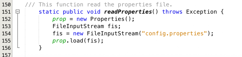
After I got done with the main program, I went back and fixed the ProcessEvents program to read its properties from the “config.properties” file.
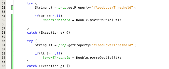
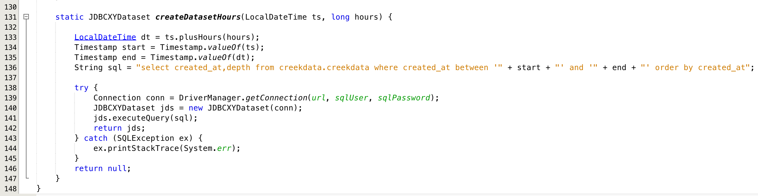
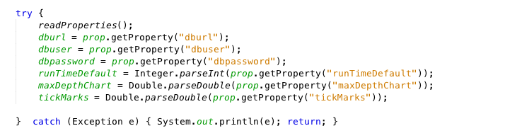
Finally, I fixed the properties problem in the MakeChart program:
All of this code is available on the iotexpert github.
In the next post I am finally going to move into the JSP and Servlet code that builds the main site.
| Index | Description |
|---|---|
| The Creek: IOT for the Elkhorn Creek | Introduction |
| The Creek: Solution Architecture 1.0 | Overall architecture |
| The Creek: Creek Board 1.1 | Eagle layout of the board |
| The Creek: Creek Board 1.0 – RCCA | A discussion of the errors in the 1.0 board |
| The Creek: CYPI, a Raspberry Pi to Arduino Bridge | PSoC4 <--> Raspberry Pi Bridge Board |
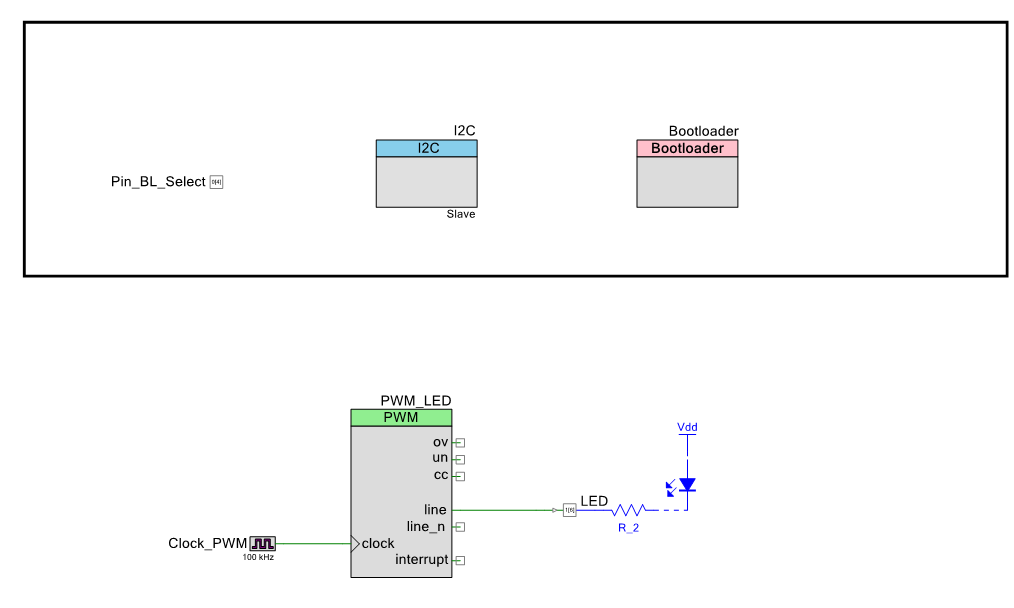
| The Creek: PSoC4 Creator Schematic and Firmware | Firmware to interface with the temperature and pressure sensors |
| The Creek: Testing the Firmware | Using tools to verify that the PSoC 4 Firmware is working correctly |
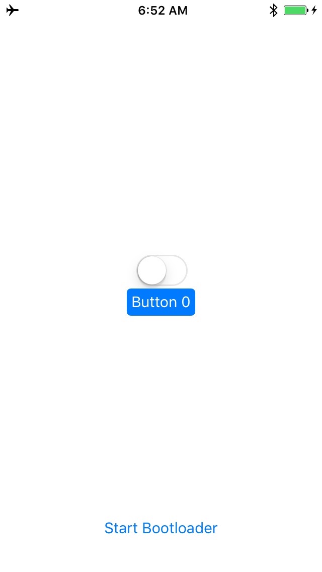
| The Creek: Testing the Bootloader | Make sure that you can load new firmware into the PSoC |
| The Creek: Software Architecture | All of the Raspberry Pi software connections |
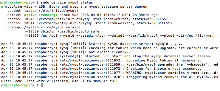
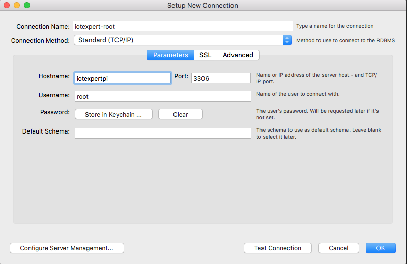
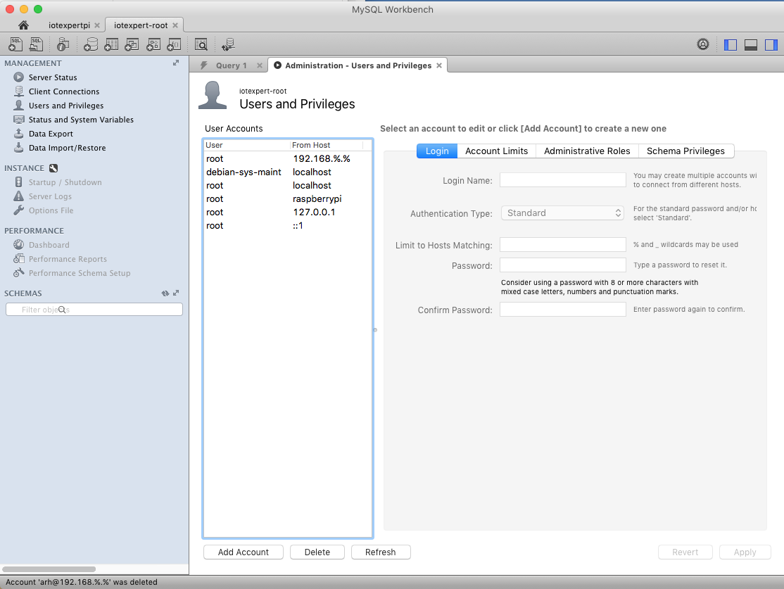
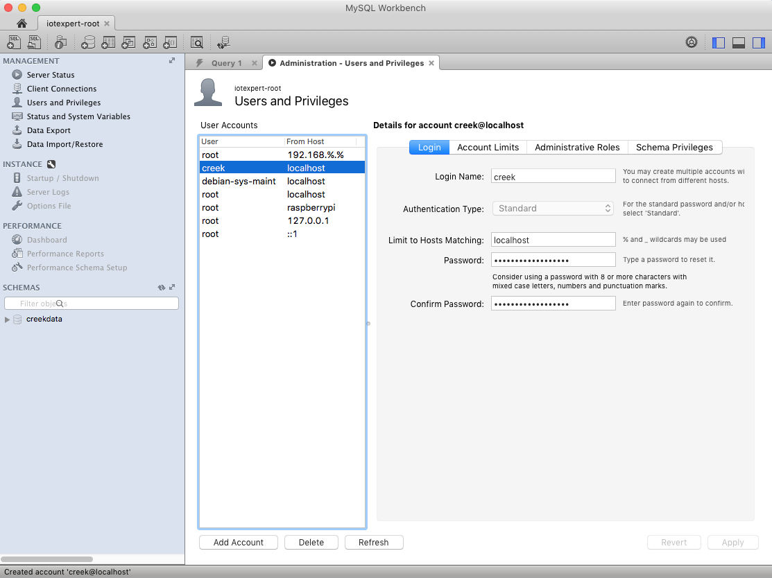
| The Creek: Install MySql | Instruction to configure MySql |
| The Creek: Install Tomcat | Instruction to configure Tomcat JSP Server |
| The Creek: Data Collection Java (Part 1) | The Java program that reads the I2C and saves it in the database |
| The Creek: Data Collection Java (Part 2) | The Java program that reads the I2C and saves it in the database |
| The Creek: Create the Chart with JFreeChart | Using open source Java charting software to create plots of the Creek Depth |
| The Creek: Flood Event Data Processor | A batch program to create analyze the database and create a table of flood events |
| The Creek: Flood Event Web Page | A batch program to create the flood event web page |
| The Creek: Creek Server 1.1 | Updates to all of the back off server programs to integrate charts |
| The Creek: JSP Web Page for www.elkhorn-creek.org | The JSP program to make the table and display the website |
| The Creek: Raspberry Pi Clock Stretching | Sorting out a bug in the system having to do with the Broadcomm Raspberry Pi Master not functioning well with clock stretching |
| The Creek: Creek Server 1.2 | Caching the web pages to make them faster |