I’ve been working on a PSoC5lp design that measures the voltage and current of a programmable VIO power supply. The PSoC5 board plugs into a Raspberry Pi and communicates over the UART. The board uses both the +5V which comes directly from the microUSB connector and the 3.3V power which is regulated on the RPi board and then shipped up the GPIO connector. I am able to measure the voltage going out (which can vary between 1.5 and 4.5V) just fine with the SAR ADC on the PSOC5. The problem is that the current measurement would vary by over 10% depending on when it was measured.
Measuring Voltage and Current
The voltage measurement is straightforward and simply measures the voltage across a 1/3rd voltage divider. The voltage divider is used to bring the input down to below the 2.048V input range of the SAR. There are lots of ways to do this but I found it was best to get the voltage down away from the rail for more accurate readings. The voltage reading works well because the input voltage swing is from .5 to 1.5V which gives plenty of range for a fairly accurate reading.
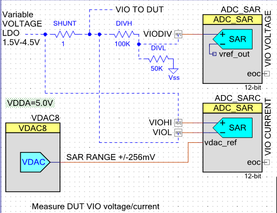 The current measurement is done by measuring the differential voltage across a 1 ohm resistor as shown in this schematic diagram. The current can vary between 0 and 250mA. With a 1 ohm resistor we’ll have a maximum of 250mV of voltage drop across the one ohm resistor. Plenty of resolution and most of the time I’ll be measuring currents in the 30 to 50mA so the voltage drop across the resistor isn’t an issue. The problem with measuring the current is that the voltage across the one ohm shunt resistor is relatively small – only 50mV and we need at least 1mA or 1mV resolution to be able to measure the current with any significant accuracy. What this means is that noise can play into this measurement and drastically reduce the accuracy.
Measuring Current is susceptible to VDDD noise
Initially the current reading was acceptable but seemed to vary sometimes but I couldn’t correlate exactly why – but it was close enough. I was using a Raspberry Pi2 Model B+ and the noise was small enough that it didn’t present a big problem but I did note that there was something not quite right. When I moved to the Raspberry Pi3 (which adds Wifi and Bluetooth and ups the GHz of the processor) the accuracy of the current measurement dropped to the point of being unusable. I had also gotten new PSoC5 PCBs so I thought my problem was on my new board. I spent a couple of weeks chasing noise down and adding 1000uF caps to try to clean things up but nothing worked.
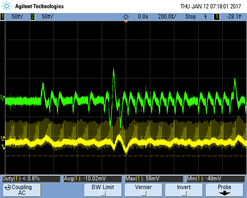 To track down the culprit of the noise I used a PGA and the same inputs to the SAR and routed that out a pin of the PSoC. That’s the really great part of the PSoC – you can change anything on the fly, download new code and bring out signals that help to debug these squirrely issues. I quickly concluded that my noise problem was correlating with the VDDD power supply to the PSoC5LP. Why the DIGITAL power supply is having such a large impact on the ANALOG portion of the PSoC I’m not quite sure but clearly it is. The green trace here is the 3.3V VDDD at the pin of the PSoC (AC Coupled). The yellow trace is the output of the PGA which is connected to the VIOH and VIOL signals in the schematic above. The small spikes from the PGA are caused when the SAR samples the VIO H/L signals. I suspect I should put a buffer on them or more likely use the DelSig which has the input buffer and a PGA. The bigger problem are the wiggles from the VDDD supply. When the SAR samples these wiggles they resulted in variations of over 10% which of course makes the current measurement almost useless. Finally it occurred to me that I had changed too many variables and I should go back to using the RPi2 and VIOLA – the noise is was within acceptable ranges on the RPi2! The problem is caused but he RPi3 3.3V having a lot of noise on it and that is then feeding into the PSoC.
My immediate solution is to stick with the RPi2 but longer term I’ll have to switch to using regulators to provide clean power to the PSoC5. Then I should be able to measure the voltage and current with much greater accuracy.
Learning – PSoC VDDD has to be clean for accurate analog
My learning from this project is that the PSoC VDDD has to be clean as well as the VDDDA. I also learned that the RPi3 3.3V power supply is terrible. The 5.0V supply comes straight from the microUSB connector and it has a lot of noise on it and cannot be used directly if you need a clean supply. My plan is to add a couple of LDOs, one for the analog supply at 4.7V and the other a nice clean 3.3V both generated from the 5.0V from the RPi. I use a 5.2V USB power supply so I have almost a half volt of margin for the LDO at 4.7V.
I also learned that I need to move a few pins around. Specifically the OpAmps have to pass thru fixed output pins so if you want to use them, you can’t use those pins for other things. The Vref external cap pins for the two SARs and the DelSig should also be connected to caps as the Vref definitely improves a lot with even 0.1 uF caps on the pins.
My main job is a Z-Wave expert consultant developing wireless IoT devices. Check out my blog at DrZwave. If you have any Z-Wave questions – send me a note!