In the previous post I showed you how to build firmware to drive the LED matrix. That firmware is in my TestMatrixBlinking project as led.h and led.c. All that is pretty cool, but what I would really like is a component that is in a library, that I can configure the number of rows/columns and the update frequency–just like the other PSoC Components. To do that I will go through the following steps
- Create a new library project
- Create a new component and symbol in the library
- Add the led.h to the header of the component
- Add the led.c to the implementation for the component
- Update the component properties to have the update frequency, number of rows, number columns etc.
- Add a reference the library in a test project
- Make the test project
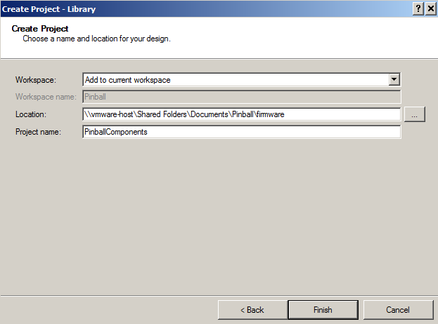
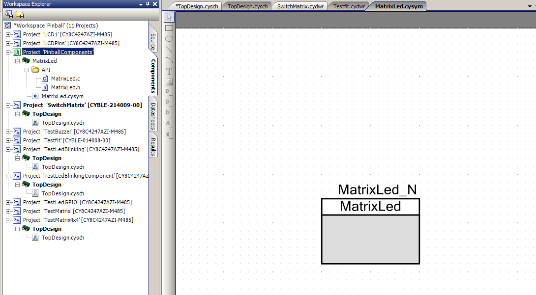
First create a new project in the workspace. In this case, I will build a library project. A library project can’t be programmed into a board, but instead is used to hold components.
Ill name the project “PinballComponents”
Then I will create a new component. To do this click on the components tab in the workspace explorer (in this picture you can see that I already added the new component)
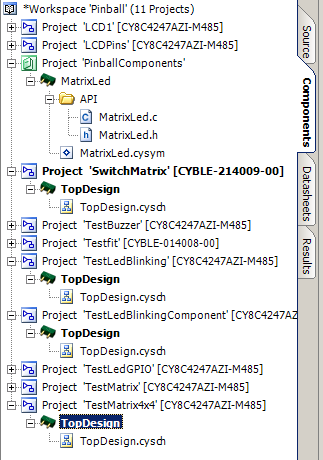
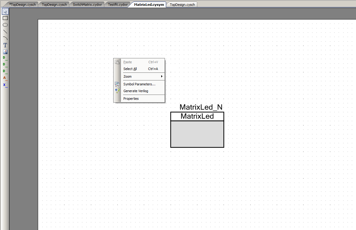
Next right click on the “PinballComponents” tab and select “Add Component Item”. Then pick Symbol Wizard and name your Component “MatrixLed”.
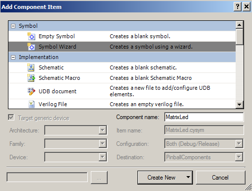
After you do that you will have “MatrixLed.cysym” in your library project.
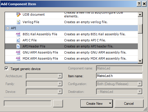
Now you need an API header file for the component. To get this, right click MatrixLed and do “Add Component Item”. Then select “API Header File” and tell it your header file will be MatrixLed.h
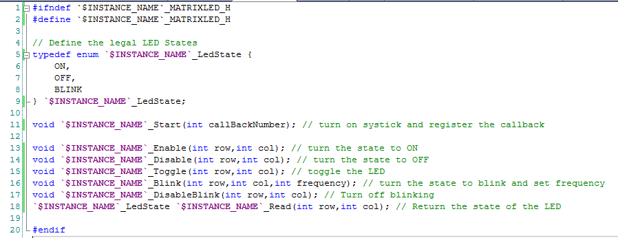
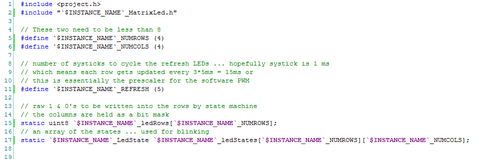
Now copy the source code from led.h into MatrixLed.h. Replace “MatrixLed” with “`$INSTANCE_NAME`”. When PSoC Creator builds your project it will replace the $INSTANCE_NAME with whatever you name your instance.
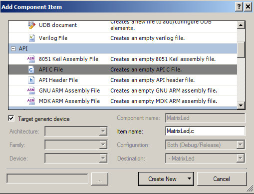
The next step is to create the implementation. To do this right click on MatrixLed and then select “Add Component Item”. Pick “API C File” and name it MatrixLed.c
Copy the source from “led.c” into the “MatrixLed.c”. Replace MatrixLed with “`$INSTANCE_NAME`” just like you did in the .h file.
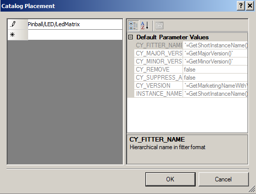
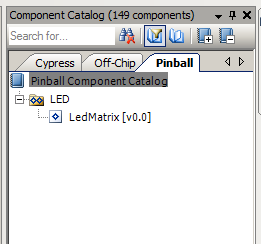
Now, right click on a blank space on the canvas in the symbol screen, then select “Properties”. On the property “Catalog Placement” type in “Pinball/LED/LedMatrix”. This will name a new tab for the component browser, a new subcategory and the name of the component.
This is how it will appear in the Component Catalog.
Now right click on the symbols canvas and select “Symbol Parameters”.
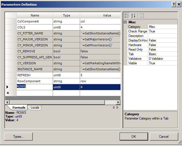
The symbol parameters will show up in the component customizer when the user double clicks. Add five parameters:
- ColComponent as a string and a default value of “col” (this is the name of the pins component that you will use for the rows)
- COLS as uint8 and a default of 4
- ROWS as uint8 and a default of 4
- RowComponent as a string and a default value of “row” (this is the name of the pins component that you will use for the columns)
- Refresh as a uint8 with a default of 5 (this will set the #define for the Refresh rate)
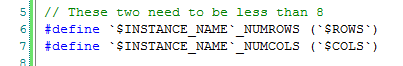
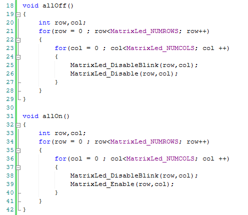
Next I realized that if I move the “NUMROWS” and “NUMCOLS” macro from the .c to the .h I will be able to use those macros in my main.c
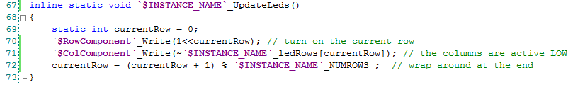
Then I modify the .c writes to the pins to have the names of the components
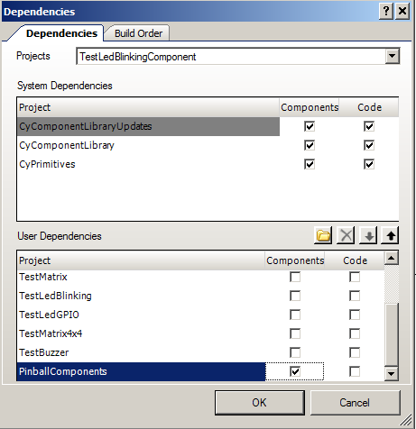
The last step is to create a test project to make sure that everything works. I create a new project called “TestBlinkingComponent”. In order to access the Pinball Components you need to add a dependency to the new project. To do this right click the new project in the workspace explorer and select “Dependencies…” then add “Pinball Components” to your list by clicking the “Components” checkbox.
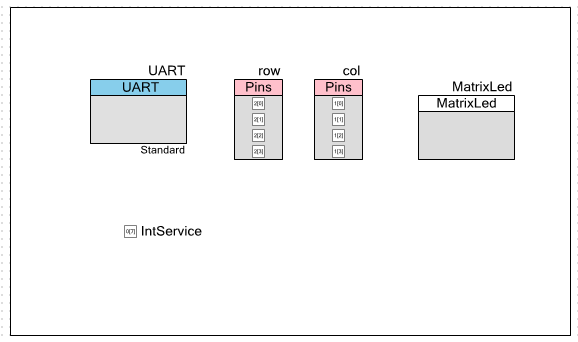
Now I make a schematic that looks like this.
Because I moved the #defines to the .h file I can use them in the main project. You can see that on line 21 where I reference MatrixLed_NUMROWS
That is it for the component. You can find it and the test project (TestLedBlinkingComponent) on github.
You can find all of the source code and files at the IOTEXPERT site on github.
Index
Description
Pinball: Newton's Attic Pinball
An introduction to the project and the goals
Pinball: Lotsa Blinking LEDs
Everyone needs a bunch of LEDs on their Pinball Machine
Pinball: Matrix LEDs (Part 1)
Saving PSoC pins by using a matrix scheme
Pinball: Matrix LEDs (Part 2)
Solving some problems with the matrix
Pinball: Matrix LEDs Component
How to turn the Matrix LED into a component
Pinball: A Switch Matrix
Implementing a bunch of switches
Pinball: Switch Matrix Component (Part 1)
The switch matrix component implementation
Pinball: Switch Matrix Component (Part 2)
The firmware for matrix component
Pinball: Switch Matrix Component (Part 3)
Test firmware for the matrix component
Pinball: The Music Player (Part 1)
The schematic and symbol for a Music Player component
Pinball: The Music Player (Part 2)
The Public API for the Music Player component
Pinball: The Music Player (Part 3)
The firmware to make the sweet sweet music
Pinball: The Music Player (Part 4)
The test program for the music player
Pinball: The Motors + HBridge
Using an Bridge to control DC Motors
Pinball: The Eagle Schematic
All of the circuits into an Eagle schematic
Pinball: The Printed Circuit Board 1.0
The first Eagle PCB layout of the printed circuit board
Pinball: The PCB Version 1.0 Fail
Problems with the first version of the Eagle PCB layout
Pinball: PCB Layout 1.2 Updates using Eagle
Fixing the errors on the first two versions of the Eagle PCB
Pinball: Assemble and Reflow the 1.2 PCB
Assembling the Eagle PCB
Pinball: Testing the Eagle PCB
Firmware to test the newly built Pinball printed circuit board
Pinball: Debugging the Motor Driver
Fixing the motor driver PSoC project
Pinball: Hot-Air Reworking the Accelerometer Solder
Using a Hot-Air Rework tool to reflow a QFN
Pinball: Debugging the LM317 Power Supply- A Tale of Getting Lucky
Debugging the LM317/LM117 power supply
No comment yet, add your voice below!