I am an IoT Expert using Z-Wave to build devices like wireless motion sensors, Z-Wave interfaces for the Raspberry Pi, in-wall light switch dimmers, Z-Wave water valves and a variety of other “Things”. My current job is as a consultant providing mostly firmware that runs on the Z-Wave chips from Sigma Designs. Express Controls is my company we just recently moved into real office space as we’ve outgrown my home office. I have my own Blog at DrZWave.wordpress.com where I’ll discuss Z-Wave specific things but I’ll be an occasional contributor here on Alan’s blog with more embedded and PSoC specific topics.
History
I went to RPI in the early 1980s where I honed my skills soldering and writing software. My first two jobs were designing graphics workstations and some of very first (and very primitive) GPUs of the day. I went on to designing chips for video conferencing compression engines, the cockpit display of the F22 fighter, Wireless Ethernet (before it was a standard) and a variety of chips for big and mostly small companies. Most of the chip designs were done as a contractor while I was also starting my first company, VAutomation which made “cores” for 8 and 16-bit CPU as well as USB and Ethernet interfaces. I sold VAutomation in 2001 and started playing with Z-Wave in 2003. I am the 31st Z-Wave licensee (there are now several hundred). At that time I went to work for a camera chip company that Cypress Semiconductor purchased and then I moved into working for Cypress which is where I met Alan. I worked on many chips at Cypress and specifically on the PSoC5 family. I moved on to do my own thing in 2014 and have been building Z-Wave IoT devices since before the Internet of Things (IoT) was a “thing”. PSoCs are just so easy to use that I use them for my own products and recommend them to my clients.
If you have any Z-Wave questions – just contact DrZwave and I’ll try to respond in a timely fashion.
Volunteer
I am also a Solar Power enthusiast and renewable energy advocate. My 30 solar PV panels generate over 1MWhr each month of clean solar power which covers my electric bill. I volunteer with HAREI which is a group that helps people put solar power on their roof with paybacks in as little as 2 years.
For my next installation I decided to try automating the garage door opener. To do this I purchased:
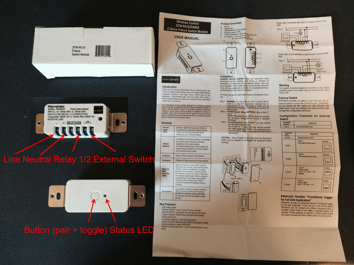
ZFM-80US Fixture Switch Module
Ecolink Garage Door Tilt Sensor
On at least one site it was stated that you should install a camera to monitor the garage door – specifically that you should look before you close the door. Ill leave that for another day. In my previous posts I described the installation of automated lights in my barn. I decided rather than try to sort out range extenders that I would install another HomeTroller something else that I plan to come back to.
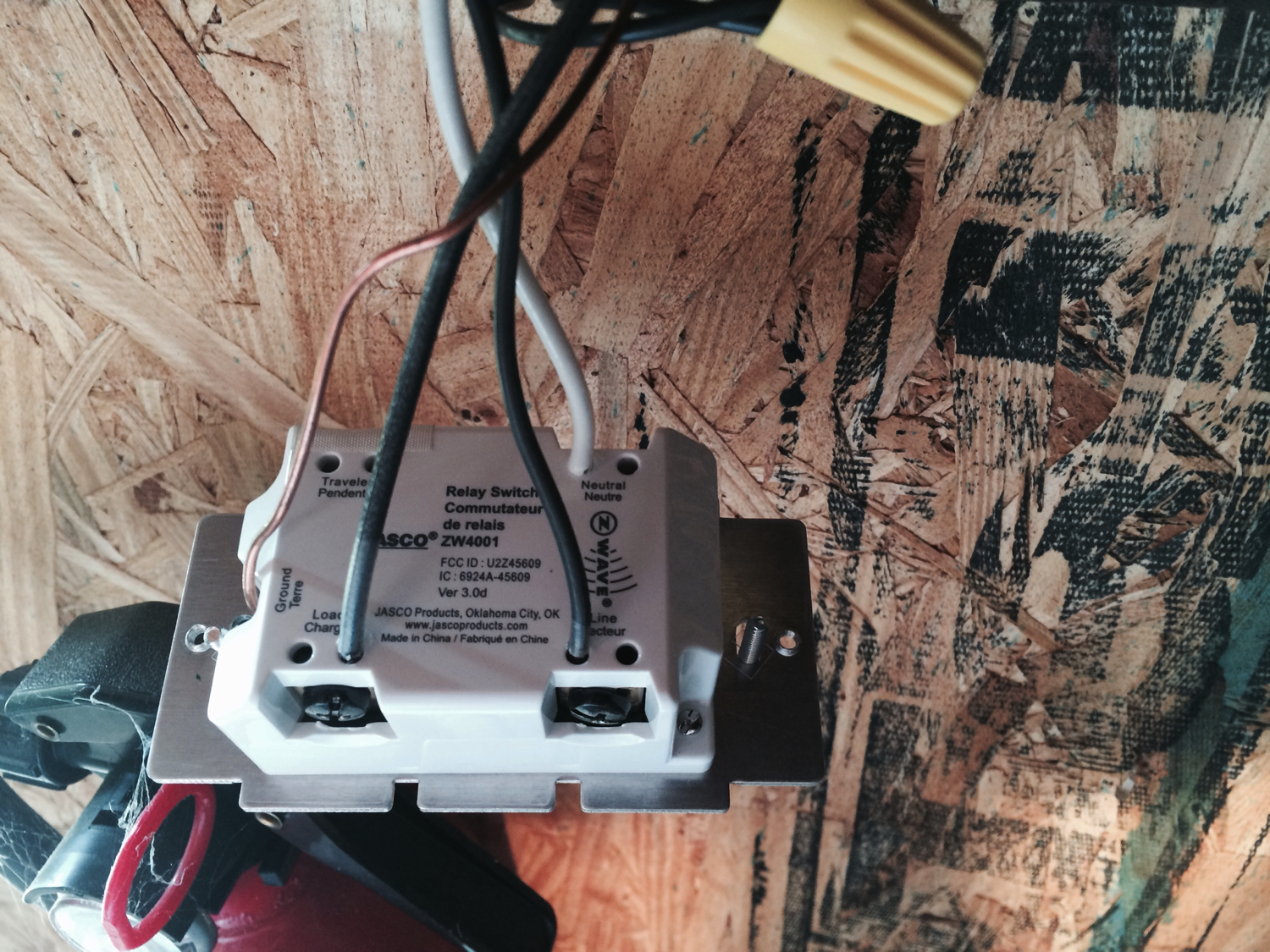
The ZFM-80 is a cool little module. It has connections for:
(L)ine and (N)eutral (to power the switch)
The two connections for the internal relay
Two connections for an external switch (you can connect a button to the switch to manually trigger the relay
The front of the switch has a status LED and a button that can serve to trigger the relay or to start pairing mode.
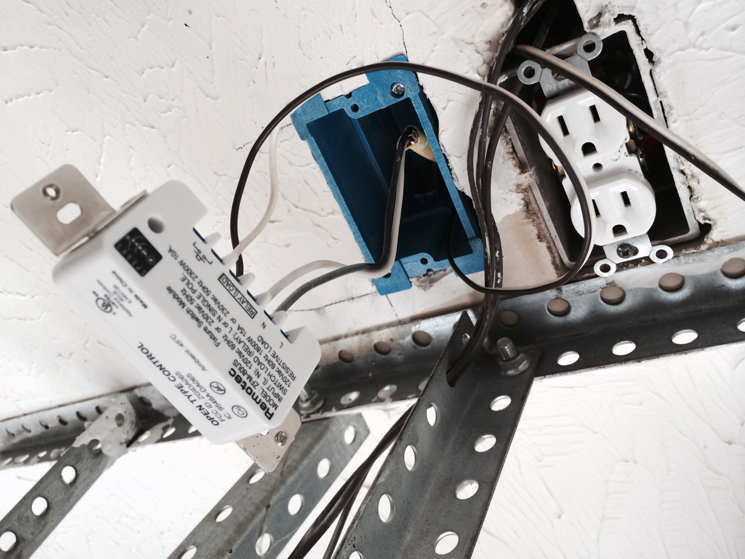
In my garage it was inconvenient to install the switch near the current garage door opener button so I decided to install it near the garage door opener power which was on the ceiling above the garage door opener. To do this I cut in an “old work” electric box. Whoever thought this type of box up was a clever person. If you have not used an old work box, start by cutting a hole in the drywall, then tighten the screws on the box which draws down two plastic clamps to hold the box in place. In order to make the switch work you need to provide it line voltage, in my case I put a wire between the plug next to my box and my box. I then attached the switch to two wires running the garage door by cutting the wires in half and shorting the relay connections to the wires.
The installation looks like this:
After that my son 10 year old son buttoned up the wires, box etc.
Nicholas installing garage door switch
The last step is to bind the switch to your network. To do this:
1. Press the button on the Zstick (1 time). The blue light will start flashing at about 1Hz
2. Press the button on the Zwave fixture switch module. The Zstick will bind with the fixture module. The Zstick will blink rapidly for about 3 seconds, then go back to 1Hz blink rate. Press the button on the Zstick to end binding mode and then re-insert the Zstick into your HomeTroller.
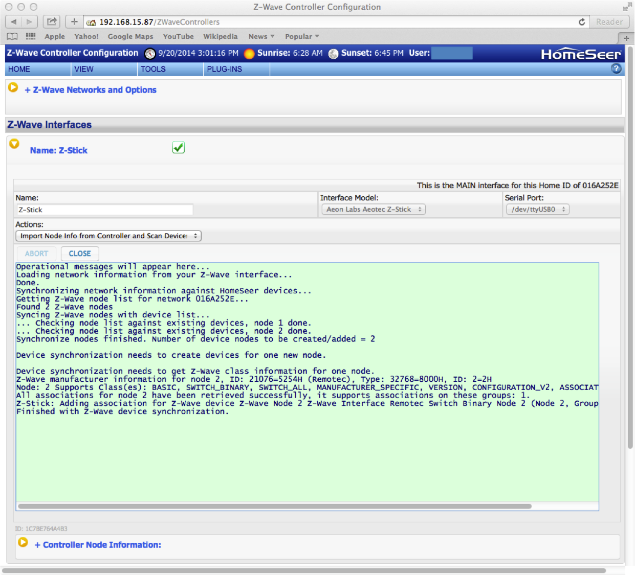
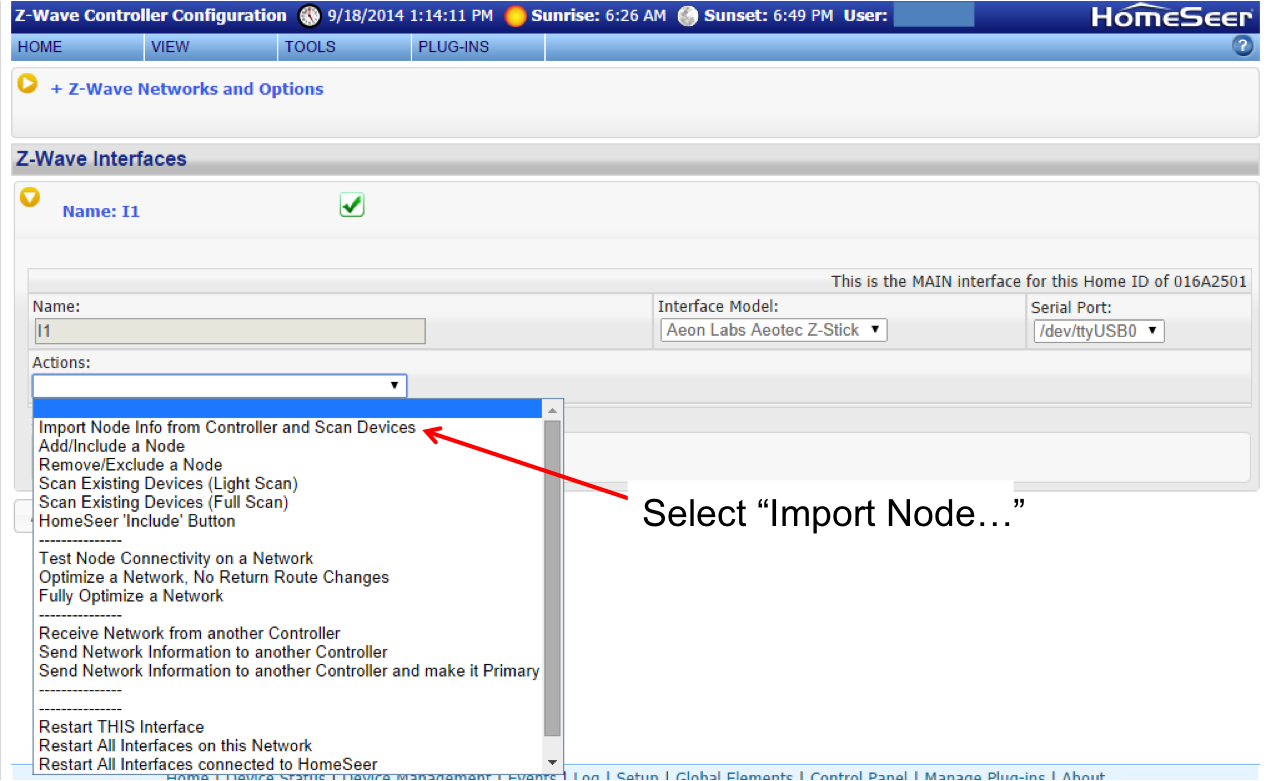
3. Go the Plug-ins->Z-wave->Controller management. Then click the yellow arrow on next to the interface. Then select “import Node Info from Controller and Scan Devices”. This will import the binding information from the Zstick
After I completed the installation of the switch I then installed the tilt sensor. This is a simple battery powered device that send out a Zwave status each time it is “tiled” (either up or down). It does this with a little mercury? switch that contacts (or doesn’t) when the switch is rotate about 90 degrees. The sensor also reports its battery status. The documentation says that the battery will last up to 4-6 years. The physical installation is simple, just attach it to the top of your garage door with the sticky tape and two screws.
To connect this device to the network
1. Click the Zstick binding button
2. Insert the battery into the Tilt Sensor
3. The Zstick will flash quickly when it binds.
4. Click the Zstick button to take it out of binding mode and re-insert it into the RPi
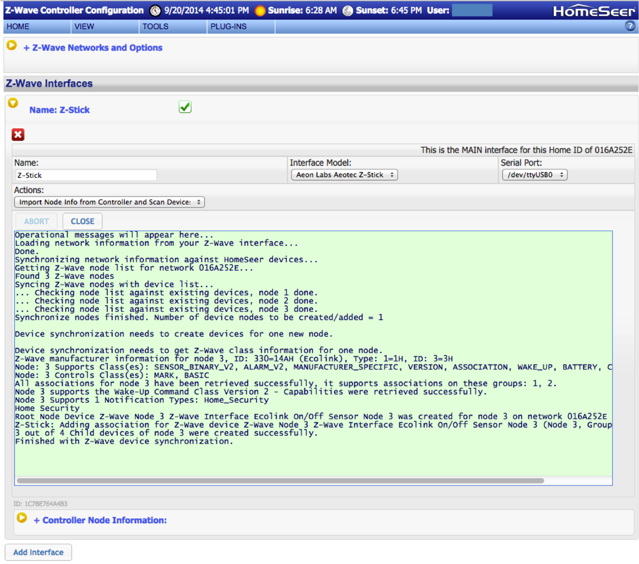
5. Go the Plug-ins->Z-wave->Controller management. Then click the yellow arrow on next to the interface. Then select “import Node Info from Controller and Scan Devices”. This will import the binding information from the Zstick
The only trick that I found with this part of the installation is that the cover must be firmly on the tilt sensor or the LED will not go out and it wont work correctly.
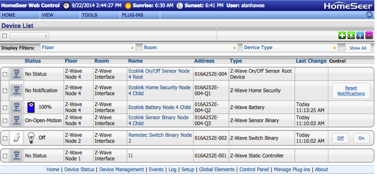
Once you have completed the two binding you will should have a device management screen that looks like this:
Notice that my tilt sensor is node-4. When I did the original import, the system got confused and I couldn’t figure out how to fix it. So, I deleted everything and re-imported the network configuration.
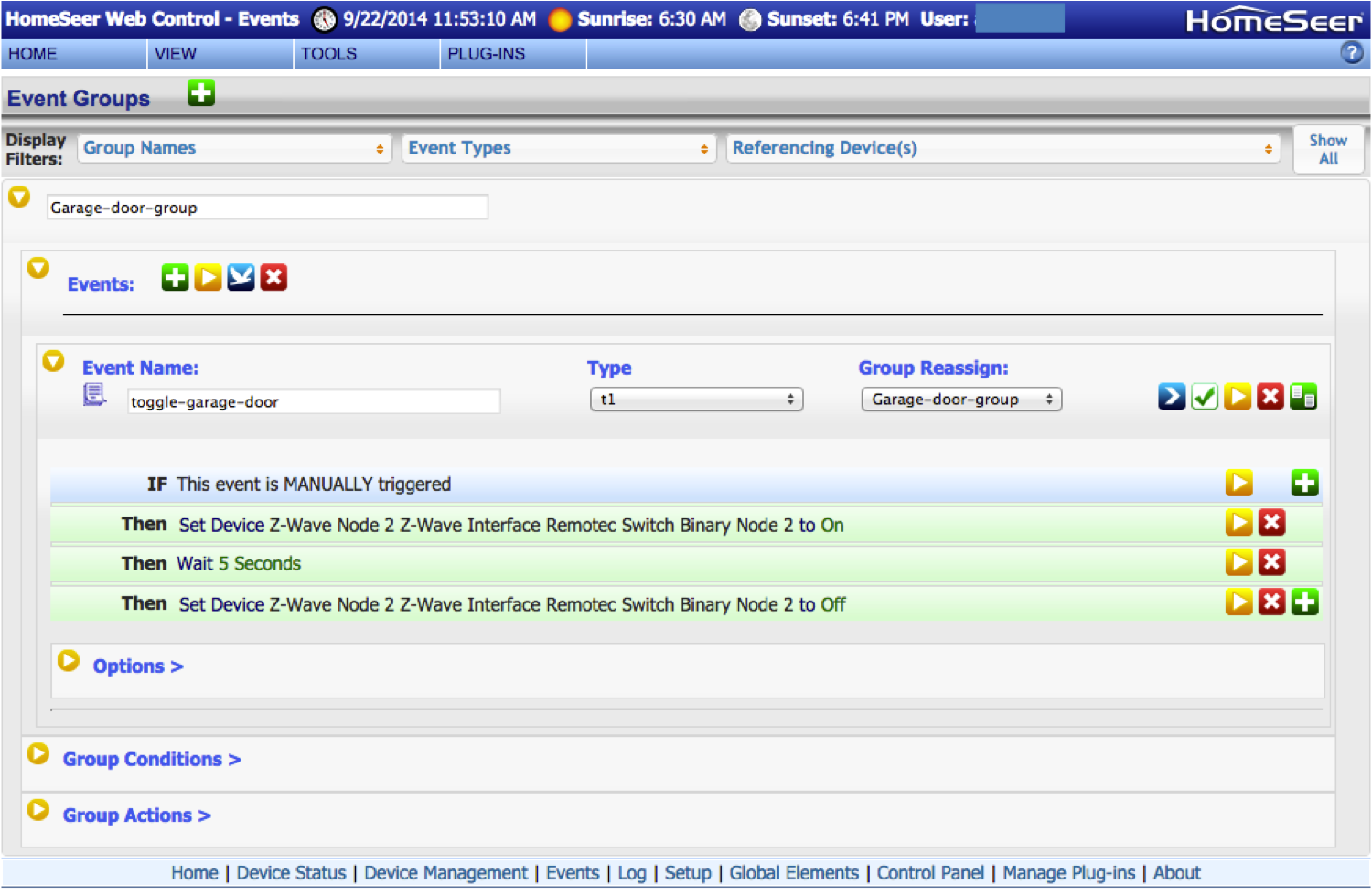
The last thing that you need to do to make this installation work correctly is to create an “event” to run the garage door. The problem is that when you “click” the switch it will toggle the relay. In order to operate the garage door you need to toggle it “on” to activate the opener, then you need to toggle it back to “off” in order to re-enable the door. To do this:
1. Go to the “View->Events” menu.
2. Click the green plus to add an event.
3. Name the event
3. Select If “This event is manually triggered”
4. Then “control a device”
5. Select your switch and set it to “on”
6. Click the green “plus” to add another step
7. Select “Then wait” and enter a few seconds (in my case I picked 5″
8. Click the green “plus” to add another step
9. Then “control a device”
10. Select your switch and set it to “off”
You should end up with an even that looks like this:
You can now run the even by pressing the “>” play button thing. I would like to be able to run this event from a simpler interface, but I don’t know how… for now anyway. Stay tuned.
If you want to control your system from an iPhone you will need to enable the HSTouch Server on your Hometrolller (it is on by default). You can do this from Plug-Ins->Manager. If HSTouch Server is disabled then you should renable it.
After you have an account you need to add your license (from the back of the HomeTroller) to your account. This will provide the connection between the HomeTroller (in your house on your private network) and the HomeSeer server (on the internet)
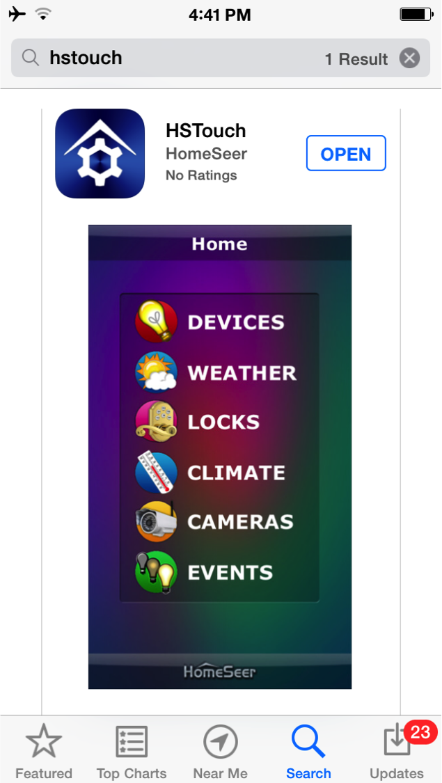
Then you need install the Apple iOS HSTouch application from the App Store
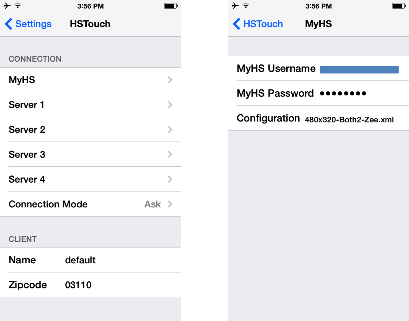
After installing the application you need to configure your account and password. To do this go to the settings menu on your iPhone and select “HSTouch”. If you dont configure the account and password the HSTouch will just crash with no explanation.
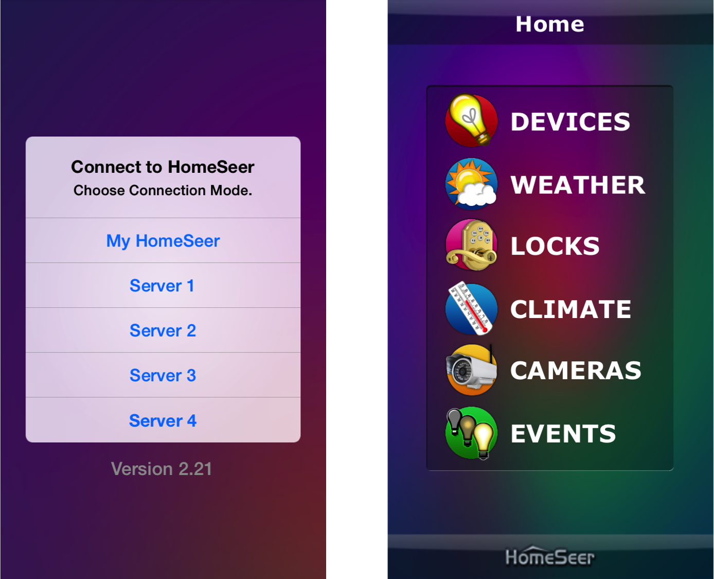
After you have configured your account and password, run the HStouch App. First select “My HomeSeer”, then “Devices”
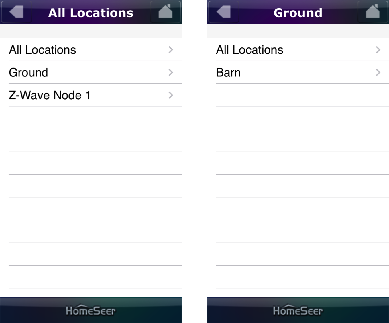
Then select the location – in my case “ground” and “barn”
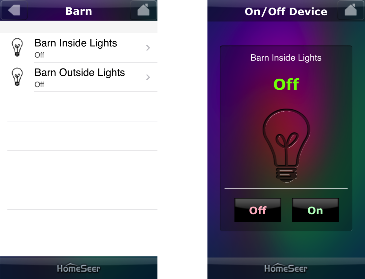
Then select “Barn Inside Lights”. Then you are able to turn them on or off.
That is it. The interface is kind of clunky, but it is functional.
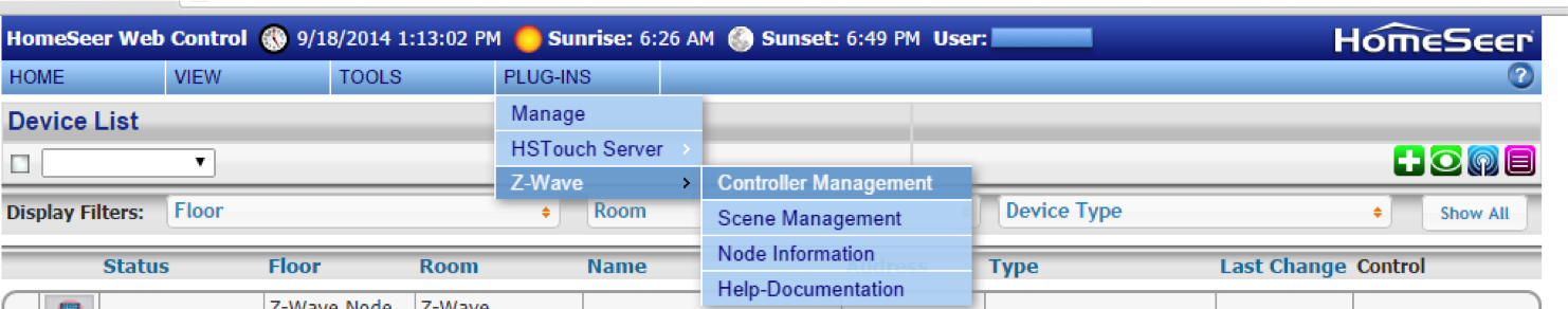
In the previous posts I installed the HomeTroller and the Zwave switch. In order to do anything you now need to read the network information out of the Zstick into the HomeTroller. In order to accomplish this first:
Select “Plug-ins->Zwave->Controller Management”
Then click the yellow arrow to open the interface menu.
Then select “Import Node Info from the Controller and Scan Devices”. This will read the binding information out of the Zstick and initialize all of the required HomeTroller databases.
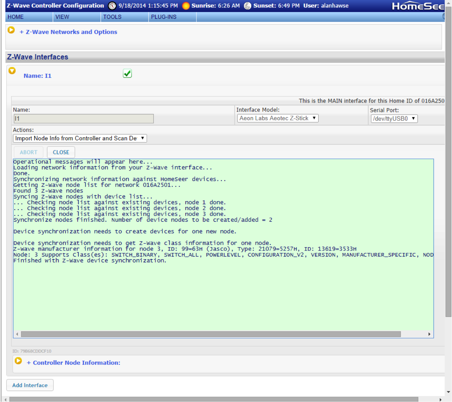
After clicking start, you will get a screen that shows the status of your import process.
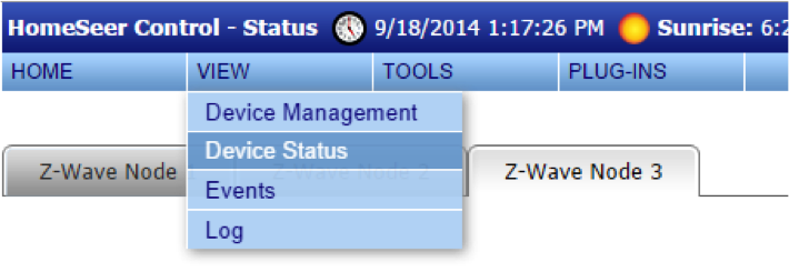
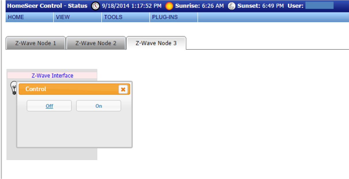
I am now able to control the lights from the web server interface. First select “View->Device Status”
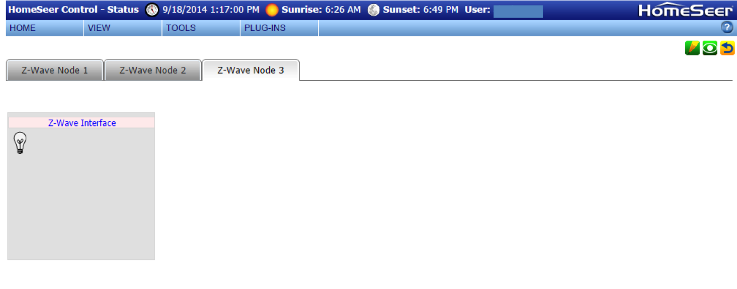
Then click on the correct “node” tab. Then click on the light bulb.
You will then be able to turn it “on” or “off”
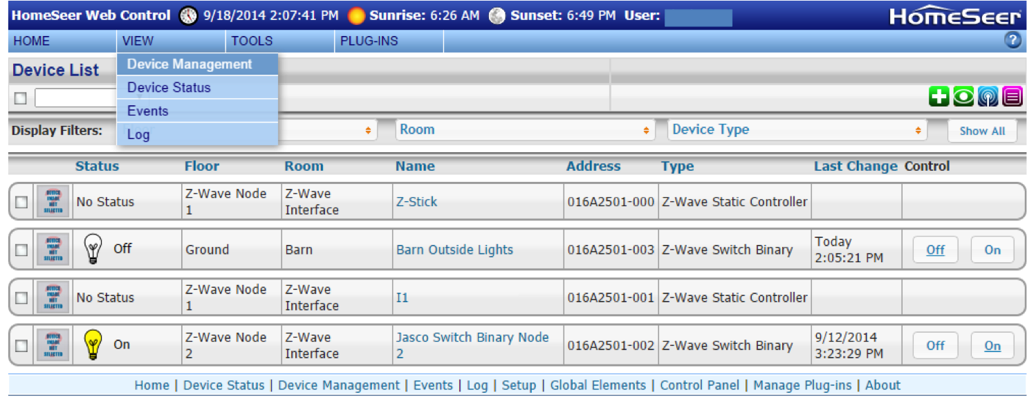
Another method is to use the “View->Device Management” screen. You will be able to turn on or off the lights from the right side of the table.
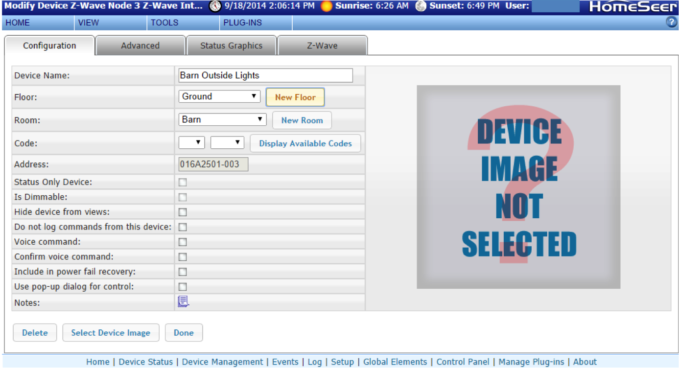
The last thing that you can do to make things a little bit simpler is to assign a sensible name and location to the switches. You do this by clicking on the current name (looks like a hyperlink). It will then show up with its new name and location.
In the next post I will describe attaching the HomeTroller to the internet and using the iOS app to control the switches.
In the previous posts, I gave an introduction to Zwave, described the overall system architecture, and demonstrated the installation of the HomeTroller Zee. In this post, I will describe the installation of the GE Zwave lightswitch and its connection to the Zwave network. The GE switch is made by a company called Jasco – which claims to be a privately owned company that “develops cutting-edge consumer products” for GE.
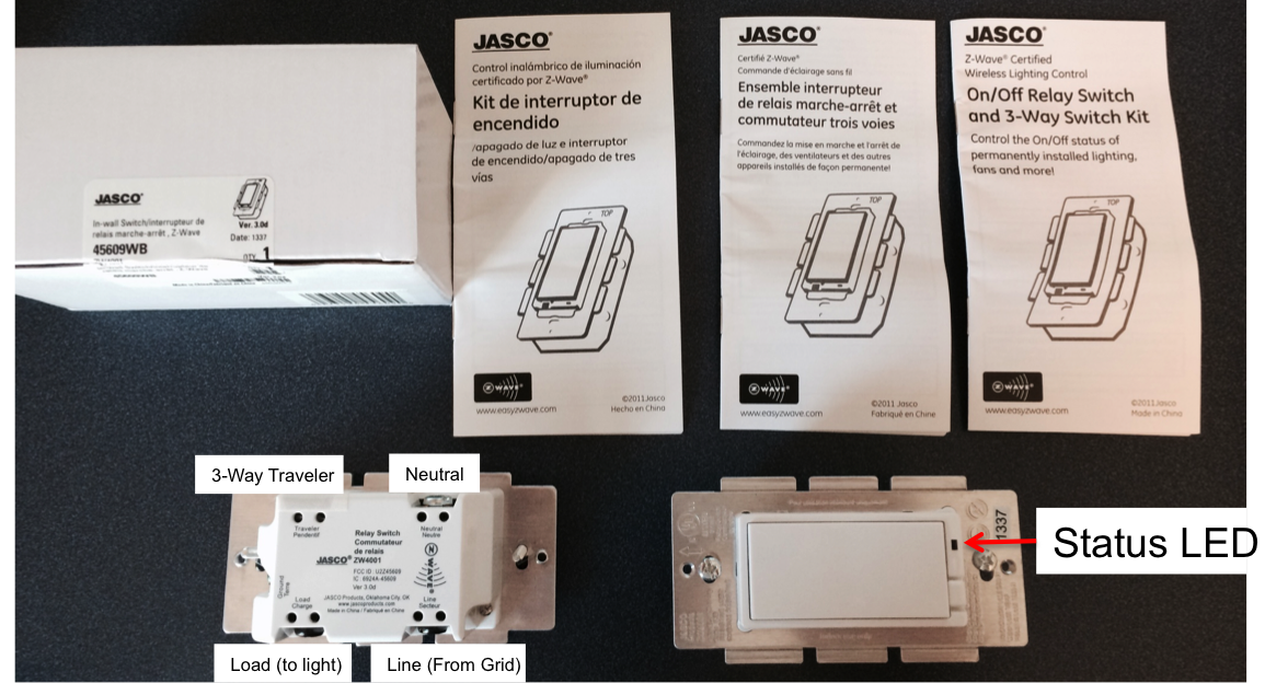
First, the lightswitch box. It contains well written instructions in three languages and the switch. The picture below shows two switches (so that I can show the front and the back of the switch in the same picture).
The next step, and the most important thing for me to do today is fervently avoid getting shocked while doing the installation. You would think that an electrical engineer would have enough sense not to install the switch without first turning off the breaker, but I always figure that I can get away without doing it HOT, a plan that invariably misfires. So, today I will start by turning of the breaker – something that I recommend you do as well.
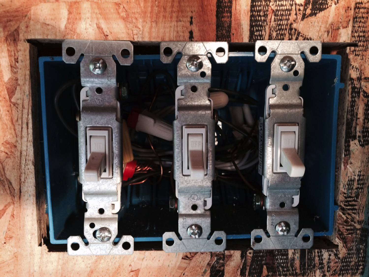
In my barn there is a group of three light switches on the “narrow” form factor. For my installation I will replace all three switches as I could only find (at Lowes) a cover plate with 3 wide holes. The switch on the left will be the barn lights (the one that gets left on my by son all the time). The other two I will replace (for now) with dumb switches that cost $2.
The next step is to install the Zwave switch. The original light switch has three connections, one bare copper ground, one “hot” wire from the line, and one wire going to the lights. The Zwave switch has four terminals, three of them are the same as the original switch and one is the added “neutral”. In order for the switch to operate it requires power and neutral to run the Zwave microcontroller – hence the need for the neutral. I created the new neutral connection wire by wire-nutting a new wire to the inside of the box attached to the pre-existing neutrals. I used a multi meter (with the power still on) to find the “hot” line side of the light switch. This was confusing as you can see from the picture the switch was installed upside down (your can faintly see the “off” label in the wrong place).
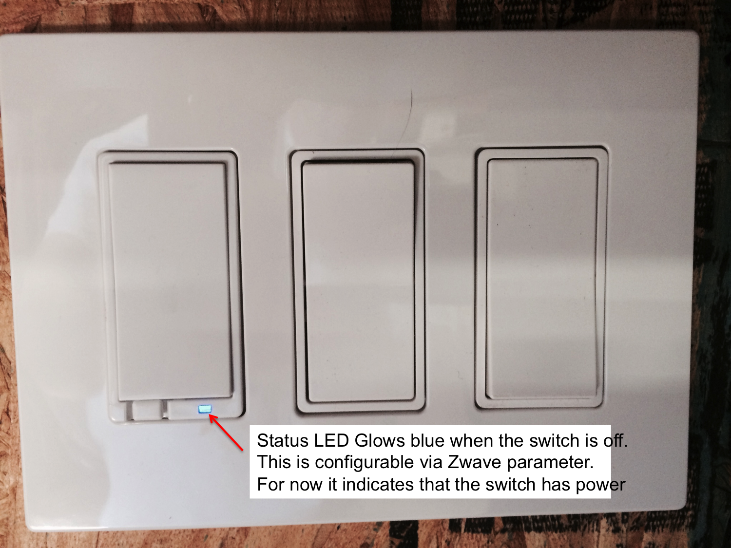
Once you have the switch wired, reassemble your box and turn the breaker back on. You should see the status LED glowing blue.
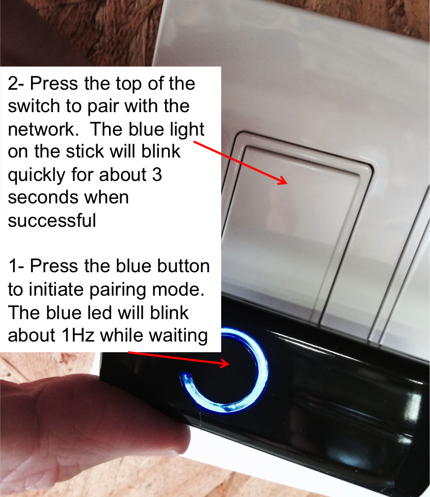
The next step is to pair the Zstick with the light switch. There is a battery in the Zstick that needs to be charged in order for this step to work. After I unboxed the HomeTroller, I plugged the ZStick into a USB port for about an hour to charge the battery. In order to launch the pairing process, start by pressing the button on the Zstick (it will then start blinking at about 1 Hz). Then press the top of the light switch (like you are turning it on). The light on the Zstick will then blink rapidly for about 3 seconds, then go back to blinking at 1 Hz. The rapid blinking indicates a successful pairing. Once you have them paired, press the Zstick button once to end pairing mode. If you had multiple devices (for instance if you were an installer) you could do more pairing before going out of pairing mode.
The next post will describe the process of reading the information from the Zstick into the HomeTroller.
This whole home automation space is crazy. It is fractured into many many different and incompatible “standards”. I have heard (though not verified myself) that many of the Zigbee radios used for home automation are not compatible and there are cases where the central hub has multiple radios to deal with the differences in the networking stacks. Other physical standards, like WiFi, have standard physical layers (802.11) and standard network layers (TCP/IP) but lack standardization higher up in the application layer.
So, Zwave. There are literally hundreds of compatible devices. And, as best I can tell, it can handle most anything that you would want or need to do home automation. I personally think that it is really cool that I can buy Zwave devices at Lowe’s in Georgetown, Kentucky. You can also buy them at Amazon, Staples and many other online places. That is pretty awesome. Zwave also seems to be one of the least expensive radio standards; you can buy modules in low quantities from Digikey for $5. The least expensive WiFi modules are something like $15 in low volume.
But it is really annoying that Sigma tries to squash the low volume market by raping their would-be customers for development kits and software licenses.
On the hub/host side of Zwave there is OpenZwave, an open source project to provide host side control of Zwave networks. The groups seems to be pretty active and I think that I will try out some of their stuff.
Like any good engineer, the first thing I did after unboxing the HomeTroller was to take it apart. In this case, I had two motives. First, I wanted to make a backup of the SD Card that runs the Raspberry Pi. Second, I am always interested in what can be learned by looking inside. In this case, you have fairly normal Rasberry Pi with a nicely executed case. The case was held together with 4 screws on the back. It included a cover for the SD card (in the lower left of the photo). The interesting thing – to me anyway – was the clear plastic LED guides. You can see them in the upper right. Their function is to redirect the light of the LEDs to come through the top of the case so as to be visible on the outside.
Included in the case is an 8 GB SD Card which holds Linux + the Hometroller software. I checked on the Homeseer web site on the Support->downloads->current downloads page and was not able to find the HomeTroller Raspberry Pi image. I found it curious that there is also a Support->downloads->older downloads which contained current software – specifically drivers.
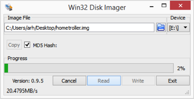
All that being said, it is good to make a backup of the SD Card before you start. For this task (on my Windows 8.1 PC) I used the Win32 Disk Imager, which can be downloaded from their Sourceforge website. If you have a Mac or a Linux computer, you can find the instructions for this process on the Raspberry Pi website. The process is straight forward. First, insert the SD Card and figure out which drive letter it was assigned using the Windows explorer. Then enter the destination file (in my case hometroller.img on the desktop), select the “copy” check box, then press read. A few minutes later, you will have a binary image file of the card which can be restored to your SD card (or another one) using the reverse process.
After you have completed the backup process, reassemble the whole thing and plug in the power and an ethernet cable. The RPi will then boot and join your network using DHCP to get its IP address. After a couple of minutes, you will be able to access the webserver running on the RPi. To find your HomeTroller, go website http://find.homeseer.com and it will search your network. In this case, you can see that I have two of them plugged in.
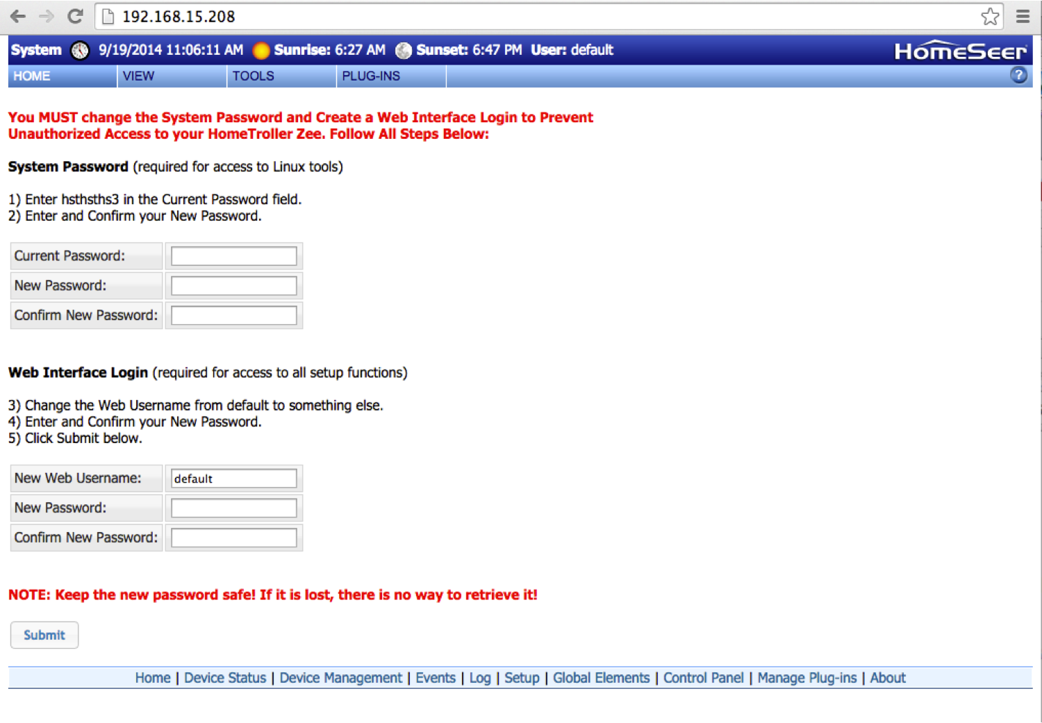
Click on IP address and your browser will open up a web page on the HomeTroller to setup the accounts and passwords.
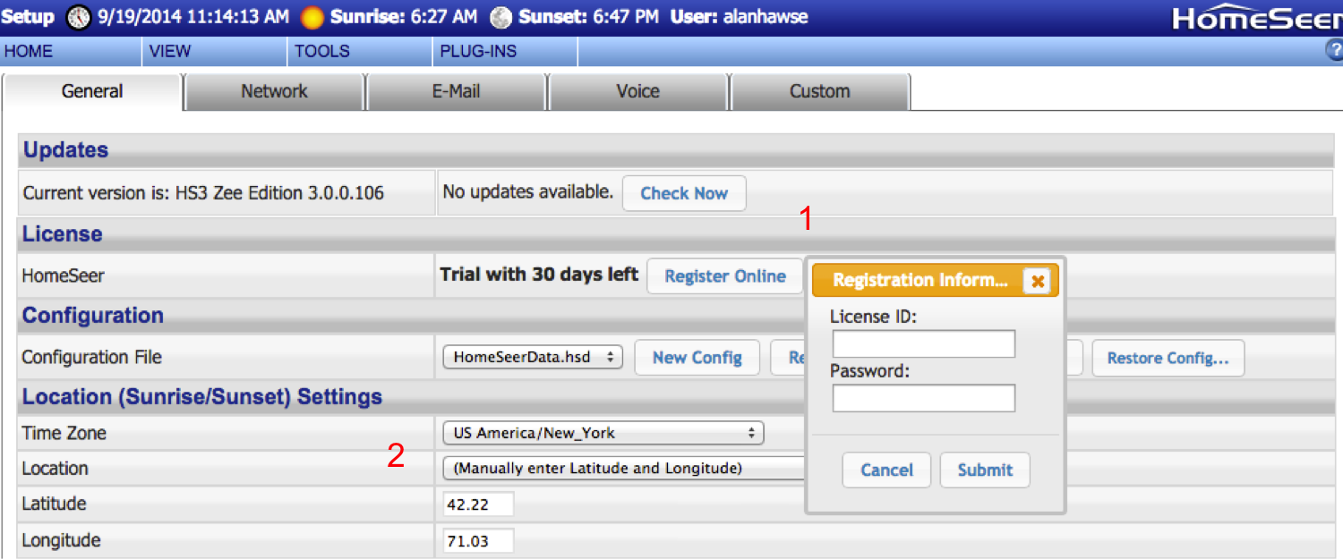
The next step is to setup your HomeTroller. To do this, go to Tools->setup. Then:
1. Enter your license information (your ID and Password is on the back of the RPi)
2. Setup the physical location and timezone.
3. If you are going to use WiFi, click on the network (1) tab and configure the SSID etc (2). In my case, I am using a USB WiPi Wifi dongle. I plugged in the dongle while the RPi was alive (specifically while I was typing this tutorial) and the RPi immediately went offline. After the system rebooted, I went to the tools->setup page, clicked the network tab, then entered my WiFi networking parameters (SSID, Security type and network key). Then I shutdown the RPi using Tools->System->shutdown. Once the RPi was shutdown, I removed the ethernet cable and then unplugged/replugged the power. After two more minutes, the RPi came back online attached to Wifi. However, just to make things interesting, it had a new IP address – because it had a new mac address, so the DHCP server assigned it a new address, so you will need to go to the find website again.
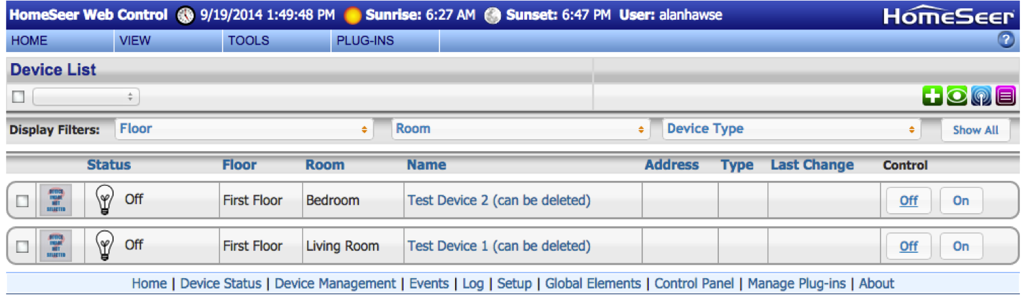
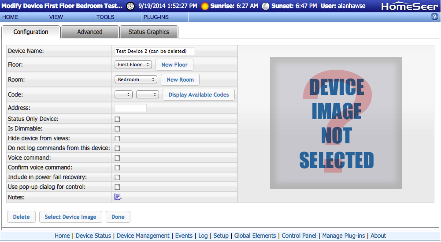
The last thing that I did after configuring my HomeTroller was clean out the bogus example devices. You can do this by going to view->device management.
Lastly, click “Test Device 2 (can be deleted) and then delete it.
In the next post, I will describe the process of installing and attaching the light switch to the network.
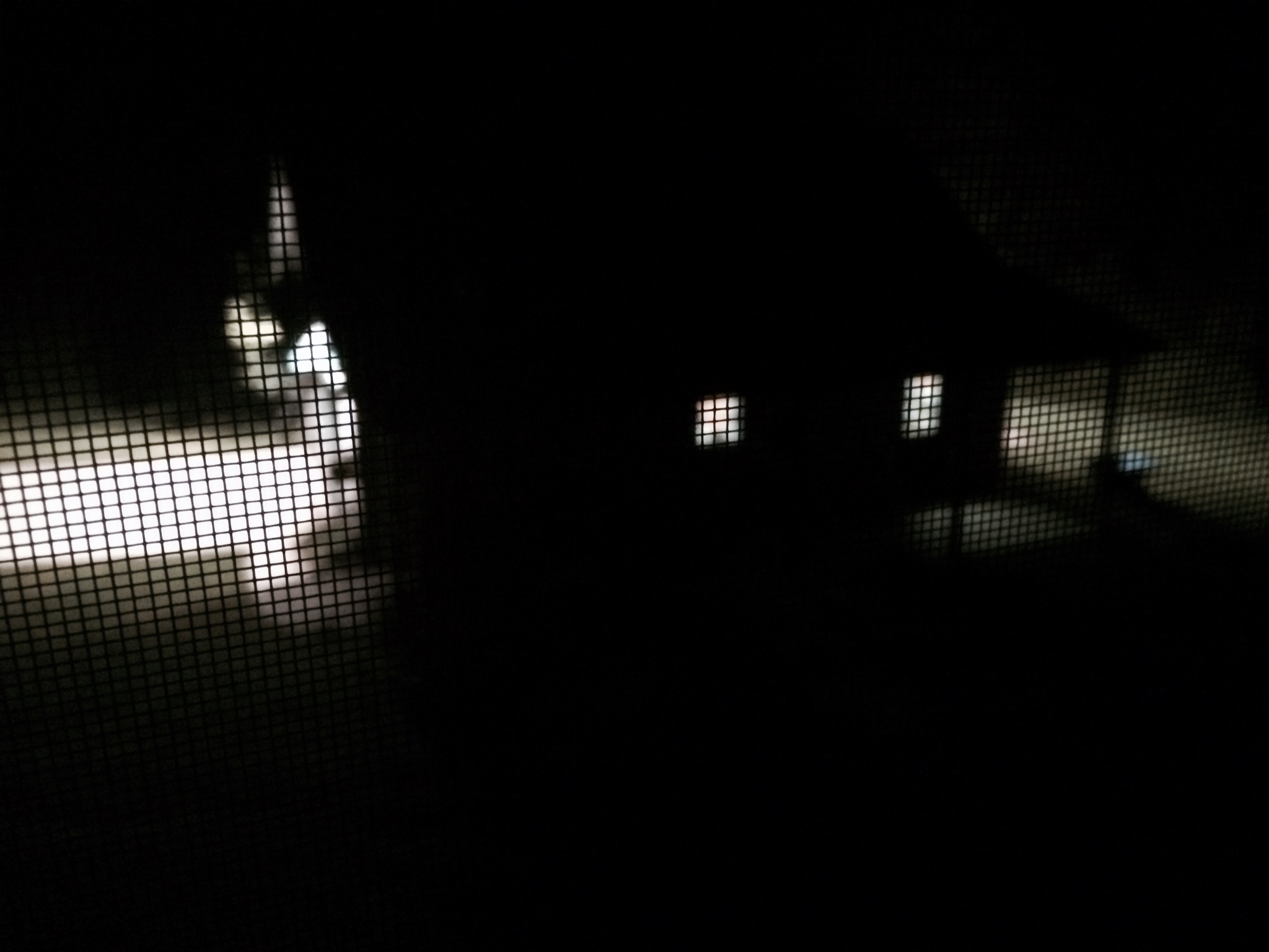
I live out in the country near Lexington, Kentucky. A few years ago my wife told me that I either needed to build a barn to store bicycles, or get a divorce. So, I built a barn – well, actually, I had a barn built. The barn has been great, except for one major pain in the neck. Invariably I look out the window at bed time and find that my son has left the damn lights on. It is incredibly annoying to go outside in the dead of winter, or even summer, in your pajamas to turn out the lights.
The barn from my window… in the dark with the lights on
After rejecting the Adrian Peterson method (wake up the kid, beat him, and then send him outside to turn off the lights), I settled on the another answer: connecting the barn lights to the Internet. I considered a number of different alternatives, but after talking with a friend of mine, Eric Ryherd at Express Controls, he convinced me to implement a Zwave home automation system.
Zwave is a proprietary 900ish MHz radio system (radio, protocol, etc), low bandwidth (100kb/s) that was designed for home automation. The “ish” is a result of the 900 MHz band not being regulated the same way in all countries. As a result, there are three different radios configurations to cover the world. Zwave has a number of attributes which make it excellent for home automation including:
Long battery life (>6 months)
Low latency
A true, simple mesh network
A single dictatorial company (Sigma Designs) controlling the protocol and certification (resulting in strong standardization)
Range in excess of 100 feet
Easy client-to-server binding
The flip side is that:
A single dictatorial company controls the standard and the silicon (resulting in insanely expensive development kits, restrictive license agreements etc)
Multiple radios required to work around the world
The other interesting thing about Zwave is that Lowe’s has made Zwave part of their Iris home automation system. This means that you can purchase some Zwave stuff at almost any of their locations – including Georgetown, Kentucky.
A GE 45609 Z-Wave Wireless Lighting Control On/Off Switch from Amazon ($40.86)
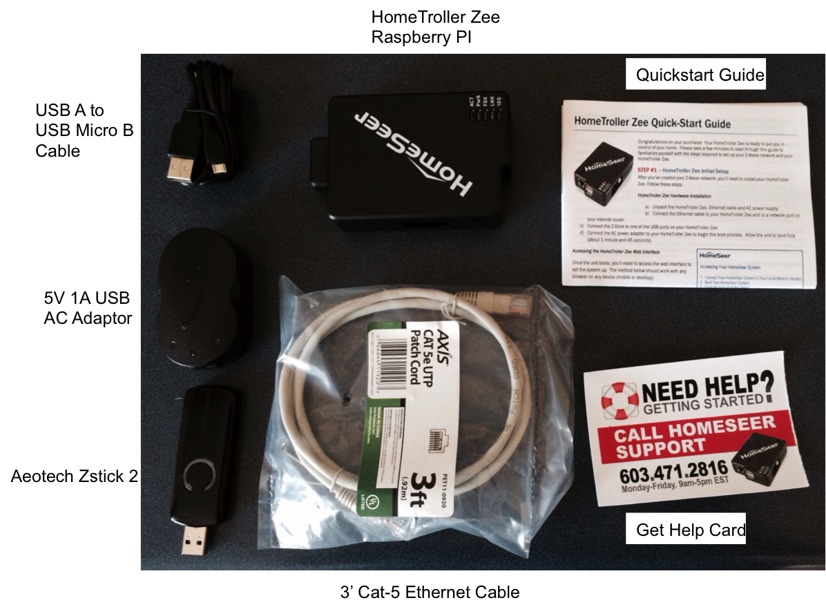
The HomeTroller Zee is a Raspberry Pi based system. The Raspberry Pi comes pre-installed with Linux, the ZStick device drivers, and the Zwave management webserver.
Included in the package is:
In order to bridge between the Zwave world and the Internet world the kit includes an Aeotec Zstick 2. This device has two functions:
It is a battery powered installation device. You can walk around with the device, press the button to start the pairing process, press the target device pairing button, which will result in the target and the stick being paired i.e. the target device is now part of the Zwave network. Then, when you plug the Zstick into the Raspberry Pi USB port, you can then upload all of the paired devices into your Zwave network configuration.
It is a USB dongle that provides the Raspberry Pi with a Zwave radio interface.
For my implementation, the overall system architecture looks like this:
The barn lights are connected to the GE switch (via normal 120v house wiring). The GE Switch communicates to the ZStick via Zwave radio. The Zstick communicates to the RPi via a USB->Uart connection. The RPi talks to the internet via Wifi (routers etc.)
In the next post I will describe the HomeTroller Zee installation.
 moved into real office space as we’ve outgrown my home office. I have my own Blog at DrZWave.wordpress.com where I’ll discuss Z-Wave specific things but I’ll be an occasional contributor here on Alan’s blog with more embedded and PSoC specific topics.