I am supposed to be good at this stuff. What is this stuff? Simple, everything engineering. Unfortunately, I suck at PCB layout. This is something that I am loath to admit because it is so frustrating. There it is. But I need a PCB to make this work, so here we go again. What also sucks is that I entitled this post “Pinball: The Printed Circuit Board Version 1.0” because I know that it is going to take multiple versions. I don’t know what the exact cause is going to be this time. But it will be something. Enough whining. Onto the task at hand.
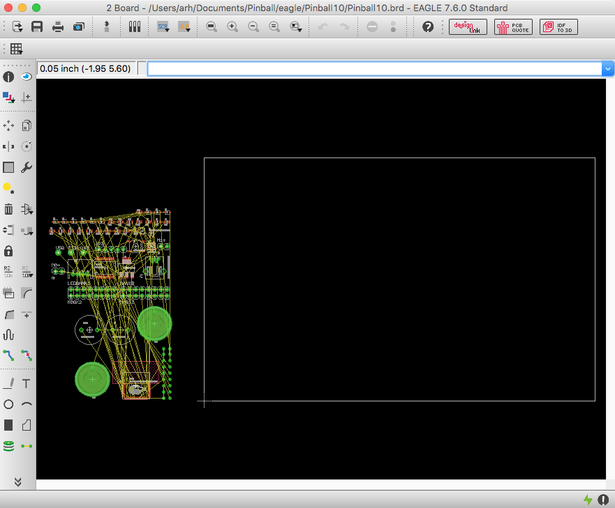
When you start from an empty board Eagle gives you the tantalizing picture of a blank board with the components you need laid out neatly. All you need to do is move them onto the tabla rosa.
Initially there are several constraints that I am trying to satisfy.
- I want the board to cost <$5 so it needs to be <5 Sq. Inches
- The Pinball machine has space on the front for something roughly the shape of a deck of cards (2.5″ x 3.5″)
- The power connector needs to be at the bottom
- The user interface needs to be at the right (buzzers, capsense buttons) because Billy is going to cover the left side with some acrylic.
We had originally thought about making a 3-D printed box for the design, but decided that it would be cool to be able to see the board. It also saves several dollars in cost to get rid of the box.
All right, I suppose that it is time to get to it. First I move all of the component from “off the board” onto the board. They all need to appear inside of the dimension layer. If you look at the pinball machine I want all of the wire to come from the top and then go down into the machine. So I place the holes for the LEDs and the Switches at the top of the board. I want the user interface to be on the right side of the board (since most of the world is right handed… sorry about the left handed people). So, I place the capsense buttons and the reset button on the right side of the board. The BLE Module needs to have the space under the antenna without a ground plane and without signals, so I decide to put it at the bottom of the board. I decide that the I2C port for the LCD will go on the left side of the board as that will make the connection to the LCD on the left side of the pinball machine easier. Finally I put the accelerometer and all of the stuff that it takes to run it on left left side as well.
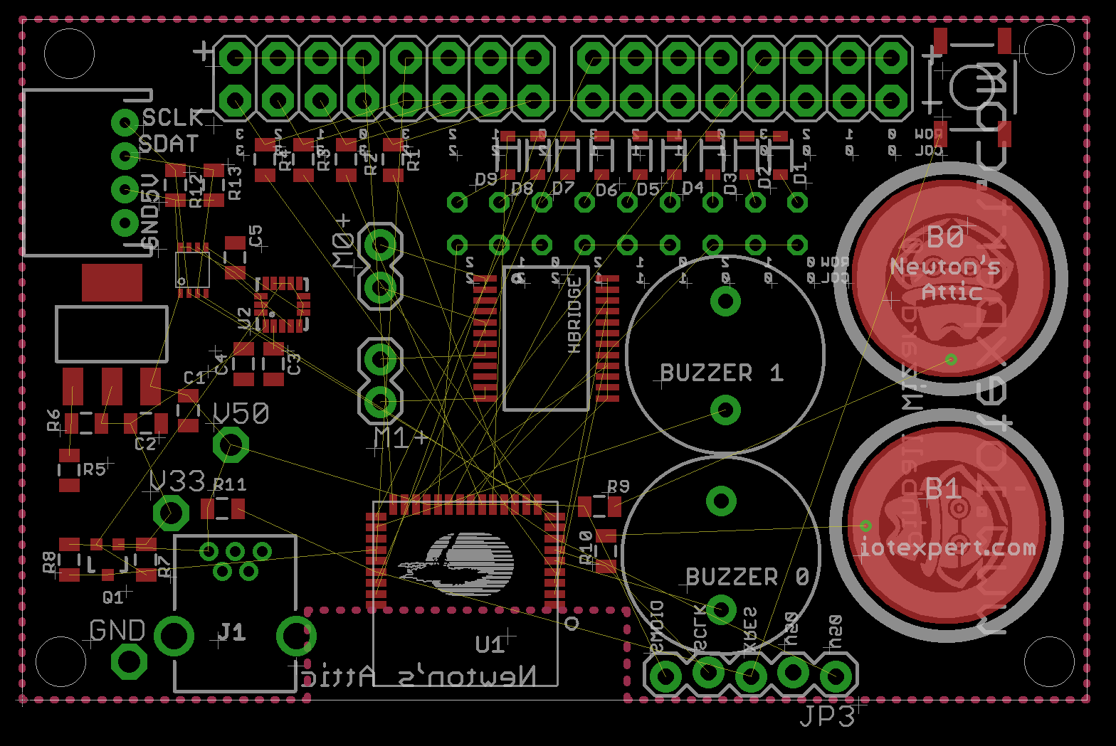
Once the placement is all done, it is time to route the signals. I do this through a combination of the autorouter and manual routes. After I get all of the routes done, I place GND via(s) all over the board to connect the top and bottom ground pours.
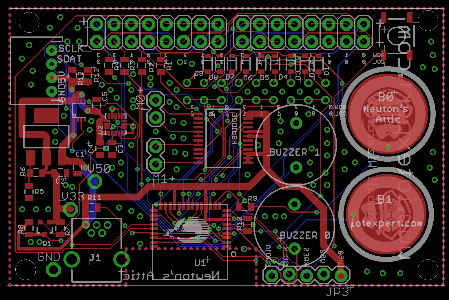
When I click the rats nest button the pours happen and I can see that there are no unrouted nets.
Next I do the top silkscreen

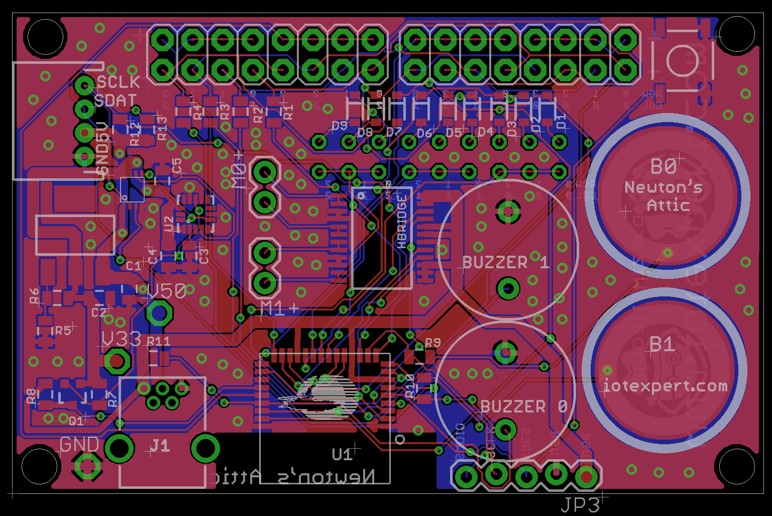
Finally the bottom silkscreen

The last step is to re-check all of my printed circuit board rules (the subject of the next post). Now that I have a printed circuit board I can send to OSHPark to be made.
You can find all of the source code and files at the IOTEXPERT site on github.
Index
Description
Pinball: Newton's Attic Pinball
An introduction to the project and the goals
Pinball: Lotsa Blinking LEDs
Everyone needs a bunch of LEDs on their Pinball Machine
Pinball: Matrix LEDs (Part 1)
Saving PSoC pins by using a matrix scheme
Pinball: Matrix LEDs (Part 2)
Solving some problems with the matrix
Pinball: Matrix LEDs Component
How to turn the Matrix LED into a component
Pinball: A Switch Matrix
Implementing a bunch of switches
Pinball: Switch Matrix Component (Part 1)
The switch matrix component implementation
Pinball: Switch Matrix Component (Part 2)
The firmware for matrix component
Pinball: Switch Matrix Component (Part 3)
Test firmware for the matrix component
Pinball: The Music Player (Part 1)
The schematic and symbol for a Music Player component
Pinball: The Music Player (Part 2)
The Public API for the Music Player component
Pinball: The Music Player (Part 3)
The firmware to make the sweet sweet music
Pinball: The Music Player (Part 4)
The test program for the music player
Pinball: The Motors + HBridge
Using an Bridge to control DC Motors
Pinball: The Eagle Schematic
All of the circuits into an Eagle schematic
Pinball: The Printed Circuit Board 1.0
The first Eagle PCB layout of the printed circuit board
Pinball: The PCB Version 1.0 Fail
Problems with the first version of the Eagle PCB layout
Pinball: PCB Layout 1.2 Updates using Eagle
Fixing the errors on the first two versions of the Eagle PCB
Pinball: Assemble and Reflow the 1.2 PCB
Assembling the Eagle PCB
Pinball: Testing the Eagle PCB
Firmware to test the newly built Pinball printed circuit board
Pinball: Debugging the Motor Driver
Fixing the motor driver PSoC project
Pinball: Hot-Air Reworking the Accelerometer Solder
Using a Hot-Air Rework tool to reflow a QFN
Pinball: Debugging the LM317 Power Supply- A Tale of Getting Lucky
Debugging the LM317/LM117 power supply
No comment yet, add your voice below!