AnyCloud Bluetooth Utilities Library

Summary

This article is a discussion of a library of utilities functions that support AnyCloud Bluetooth development.  It includes settings to configure the hardware, functions to decode stack events, functions to decode advertising packets etc.

Story

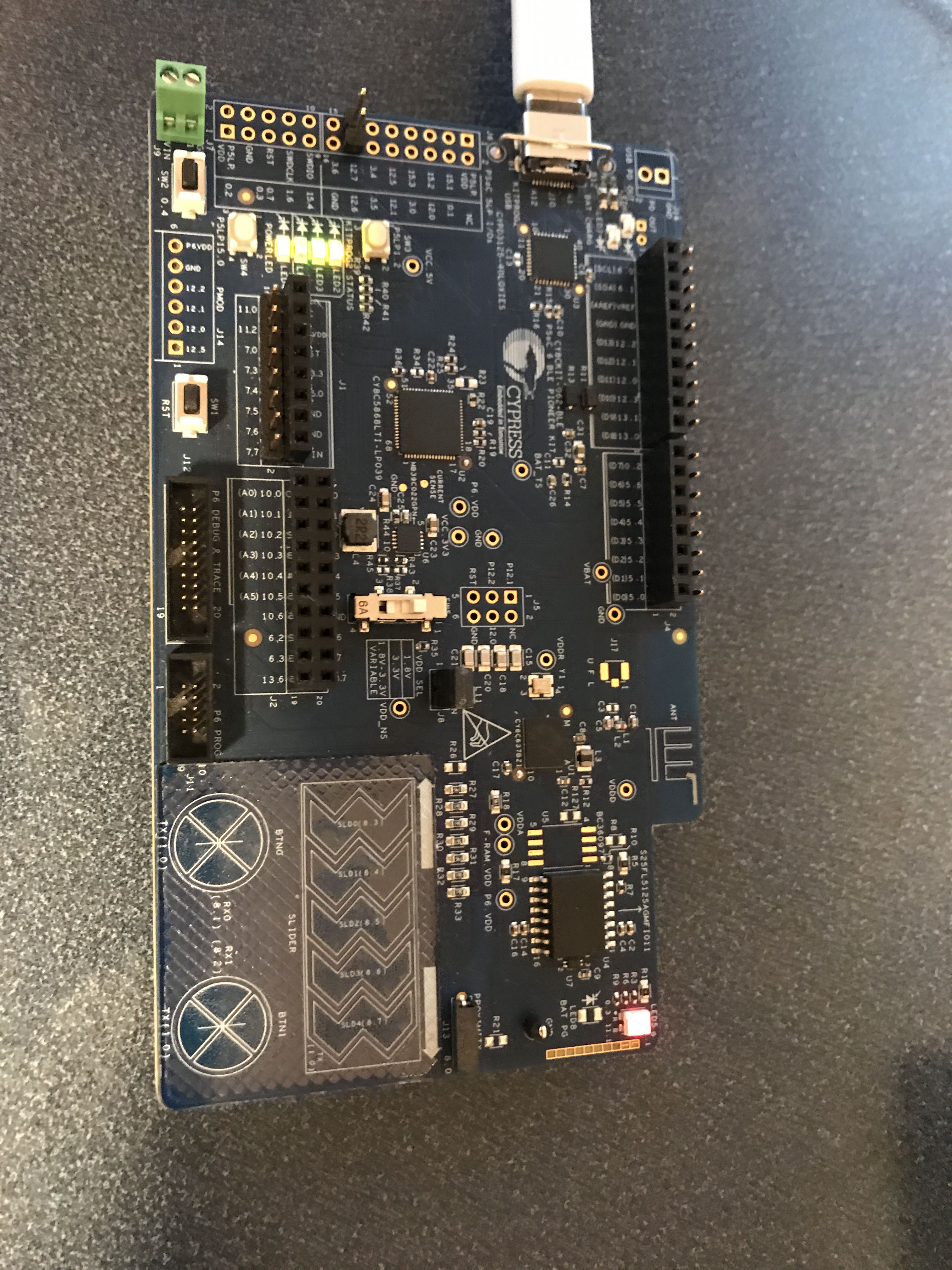
The Cypress, now Infineon, Modus Toolbox team has been working to bring the WICED Bluetooth devices to be closer and more compatible with the PSoC 6 tools.  One of the important enablement things we have done is turn on the WICED Bluetooth Host stack on the PSoC 6 so that it can effectively talk to the CYW43XXX Bluetooth / WiFi combo chips.

As I have been using all of the new stuff I found myself adding my own custom functionality…. and after a while I realized (finally) that I should put all of those little helper things into a library, specifically an IoT Expert library.  For now this library contains:

  • The Bluetooth Platform Configuration Settings
  • Functions to decode stack events
  • Functions to decode advertising packets

but imagine with time I will add more functions and templates.

bt_platform_cfg_settings

As I discussed in the article AnyCloud Bluetooth Advertising Scanner (Part 1), every single AnyCloud BLE Stack project will require a structure of type wiced_bt_cfg_settings_t.  This structure is used to setup the hardware before getting the stack going.  Remember you need to make a call like this to initialize the Bluetooth hardware.

    cybt_platform_config_init(&bt_platform_cfg_settings);

At some point this file will be included automatically for you by the Modus Toolbox team, but for now I have added this to my library.  This file look like this.  Basically a bunch of pin definitions which are set for you automatically by the BSP.  Obviously you can make your own, but this should work on all of the Cypress development kits (I think)

#include "cybt_platform_config.h"
#include "cybsp.h"
#include "wiced_bt_stack.h"

const cybt_platform_config_t bt_platform_cfg_settings =
{
    .hci_config =
    {
        .hci_transport = CYBT_HCI_UART,

        .hci =
        {
            .hci_uart =
            {
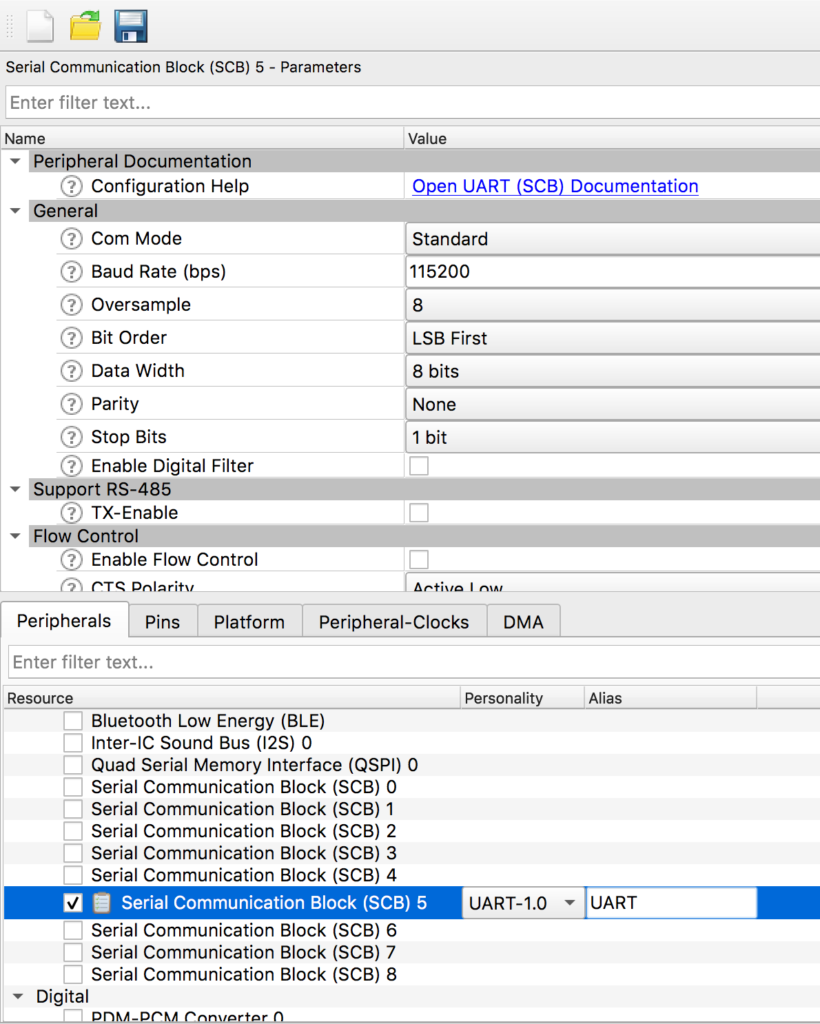
                .uart_tx_pin = CYBSP_BT_UART_TX,
                .uart_rx_pin = CYBSP_BT_UART_RX,
                .uart_rts_pin = CYBSP_BT_UART_RTS,
                .uart_cts_pin = CYBSP_BT_UART_CTS,

                .baud_rate_for_fw_download = 115200,
                .baud_rate_for_feature     = 115200,

                .data_bits = 8,
                .stop_bits = 1,
                .parity = CYHAL_UART_PARITY_NONE,
                .flow_control = WICED_TRUE
            }
        }
    },

    .controller_config =
    {
        .bt_power_pin      = CYBSP_BT_POWER,
        .sleep_mode =
        {
            #if (bt_0_power_0_ENABLED == 1) /* BT Power control is enabled in the LPA */
            #if (CYCFG_BT_LP_ENABLED == 1) /* Low power is enabled in the LPA, use the LPA configuration */
            .sleep_mode_enabled = true,
            .device_wakeup_pin = CYCFG_BT_DEV_WAKE_GPIO,
            .host_wakeup_pin = CYCFG_BT_HOST_WAKE_GPIO,
            .device_wake_polarity = CYCFG_BT_DEV_WAKE_POLARITY,
            .host_wake_polarity = CYCFG_BT_HOST_WAKE_IRQ_EVENT
            #else /* Low power is disabled in the LPA, disable low power */
            .sleep_mode_enabled = false
            #endif
            #else /* BT Power control is disabled in the LPA – default to BSP low power configuration */
            .sleep_mode_enabled = true,
            .device_wakeup_pin = CYBSP_BT_DEVICE_WAKE,
            .host_wakeup_pin = CYBSP_BT_HOST_WAKE,
            .device_wake_polarity = CYBT_WAKE_ACTIVE_LOW,
            .host_wake_polarity = CYBT_WAKE_ACTIVE_LOW
            #endif
        }
    },

    .task_mem_pool_size    = 2048
};

btutil_stack

When you startup the Bluetooth Host stack you are responsible for providing a “management callback” which has the function prototype

typedef wiced_result_t (wiced_bt_management_cback_t) (wiced_bt_management_evt_t event, wiced_bt_management_evt_data_t *p_event_data);

The first parameter is an “event” which is  just an enumerated list of possible events by the Bluetooth Host Stack.  Here is the actual list.

enum wiced_bt_management_evt_e {
/* Bluetooth status events */
BTM_ENABLED_EVT,                                /**< Bluetooth controller and host stack enabled. Event data: wiced_bt_dev_enabled_t */
BTM_DISABLED_EVT,                               /**< Bluetooth controller and host stack disabled. Event data: NULL */
BTM_POWER_MANAGEMENT_STATUS_EVT,                /**< Power management status change. Event data: wiced_bt_power_mgmt_notification_t */
BTM_RE_START_EVT,                               /**< Bluetooth controller and host stack re-enabled. Event data: tBTM_ENABLED_EVT */
/* Security events */
BTM_PIN_REQUEST_EVT,                            /**< PIN request (used only with legacy devices). Event data: #wiced_bt_dev_name_and_class_t */
BTM_USER_CONFIRMATION_REQUEST_EVT,              /**< received USER_CONFIRMATION_REQUEST event (respond using #wiced_bt_dev_confirm_req_reply). Event data: #wiced_bt_dev_user_cfm_req_t */
BTM_PASSKEY_NOTIFICATION_EVT,                   /**< received USER_PASSKEY_NOTIFY event. Event data: #wiced_bt_dev_user_key_notif_t */
BTM_PASSKEY_REQUEST_EVT,                        /**< received USER_PASSKEY_REQUEST event @cond DUAL_MODE (respond using #wiced_bt_dev_pass_key_req_reply). Event data: #wiced_bt_dev_user_key_req_t @endcond
@note  BR/EDR Only */
BTM_KEYPRESS_NOTIFICATION_EVT,                  /**< received KEYPRESS_NOTIFY event. Event data: #wiced_bt_dev_user_keypress_t */
BTM_PAIRING_IO_CAPABILITIES_BR_EDR_REQUEST_EVT, /**< Requesting IO capabilities for BR/EDR pairing. Event data: #wiced_bt_dev_bredr_io_caps_req_t 
@note  BR/EDR Only */
BTM_PAIRING_IO_CAPABILITIES_BR_EDR_RESPONSE_EVT,/**< Received IO capabilities response for BR/EDR pairing. Event data: @cond DUAL_MODE #wiced_bt_dev_bredr_io_caps_rsp_t @endcond
@note  BR/EDR Only*/
BTM_PAIRING_IO_CAPABILITIES_BLE_REQUEST_EVT,    /**< Requesting IO capabilities for BLE pairing. Slave can check peer io capabilities in event data before updating with local io capabilities. Event data: #wiced_bt_dev_ble_io_caps_req_t */
BTM_PAIRING_COMPLETE_EVT,                       /**< received SIMPLE_PAIRING_COMPLETE event. Event data: #wiced_bt_dev_pairing_cplt_t */
BTM_ENCRYPTION_STATUS_EVT,                      /**< Encryption status change. Event data: #wiced_bt_dev_encryption_status_t */
BTM_SECURITY_REQUEST_EVT,                       /**< Security request (respond using #wiced_bt_ble_security_grant). Event data: #wiced_bt_dev_security_request_t */
BTM_SECURITY_FAILED_EVT,                        /**< Security procedure/authentication failed. Event data: #wiced_bt_dev_security_failed_t */
BTM_SECURITY_ABORTED_EVT,                       /**< Security procedure aborted locally, or unexpected link drop. Event data: #wiced_bt_dev_name_and_class_t */
BTM_READ_LOCAL_OOB_DATA_COMPLETE_EVT,           /**< Result of reading local OOB data @cond DUAL_MODE (#wiced_bt_dev_read_local_oob_data). Event data: #wiced_bt_dev_local_oob_t @endcond 
@note  BR/EDR Only */
BTM_REMOTE_OOB_DATA_REQUEST_EVT,                /**< OOB data from remote device @cond DUAL_MODE (respond using #wiced_bt_dev_remote_oob_data_reply). Event data: #wiced_bt_dev_remote_oob_t @endcond 
@note  BR/EDR Only */
BTM_PAIRED_DEVICE_LINK_KEYS_UPDATE_EVT,         /**< Updated remote device link keys (store device_link_keys to  NV memory). This is the place to
verify that the correct link key has been generated. Event data: #wiced_bt_device_link_keys_t */
BTM_PAIRED_DEVICE_LINK_KEYS_REQUEST_EVT,        /**< Request for stored remote device link keys (restore device_link_keys from NV memory). If successful, return WICED_BT_SUCCESS. Event data: #wiced_bt_device_link_keys_t */
BTM_LOCAL_IDENTITY_KEYS_UPDATE_EVT,             /**< Update local identity key (stored local_identity_keys NV memory). Event data: #wiced_bt_local_identity_keys_t */
BTM_LOCAL_IDENTITY_KEYS_REQUEST_EVT,            /**< Request local identity key (get local_identity_keys from NV memory). If successful, return WICED_BT_SUCCESS. Event data: #wiced_bt_local_identity_keys_t */
BTM_BLE_SCAN_STATE_CHANGED_EVT,                 /**< BLE scan state change. Event data: #wiced_bt_ble_scan_type_t */
BTM_BLE_ADVERT_STATE_CHANGED_EVT,               /**< BLE advertisement state change. Event data: #wiced_bt_ble_advert_mode_t */
/* BLE Secure Connection events */
BTM_SMP_REMOTE_OOB_DATA_REQUEST_EVT,            /**< SMP remote oob data request. Reply using wiced_bt_smp_oob_data_reply. Event data: #wiced_bt_smp_remote_oob_req_t  */
BTM_SMP_SC_REMOTE_OOB_DATA_REQUEST_EVT,         /**< LE secure connection remote oob data request. Reply using wiced_bt_smp_sc_oob_reply. Event data: #wiced_bt_smp_sc_remote_oob_req_t 
@note  BR/EDR Only */
BTM_SMP_SC_LOCAL_OOB_DATA_NOTIFICATION_EVT,     /**< LE secure connection local OOB data (wiced_bt_smp_create_local_sc_oob_data). Event data: #wiced_bt_smp_sc_local_oob_t */
BTM_SCO_CONNECTED_EVT,                          /**< SCO connected event. Event data: @cond DUAL_MODE #wiced_bt_sco_connected_t @endcond
@note  BR/EDR Only */
BTM_SCO_DISCONNECTED_EVT,                       /**< SCO disconnected event. Event data: @cond #wiced_bt_sco_disconnected_t @endcond
@note  BR/EDR Only */
BTM_SCO_CONNECTION_REQUEST_EVT,                 /**< SCO connection request event. Event data: @cond #wiced_bt_sco_connection_request_t @endcond
@note  BR/EDR Only */
BTM_SCO_CONNECTION_CHANGE_EVT,                  /**< SCO connection change event. Event data: @cond #wiced_bt_sco_connection_change_t @endcond
@note  BR/EDR Only */
BTM_BLE_CONNECTION_PARAM_UPDATE,                /**< BLE connection parameter update. Event data: #wiced_bt_ble_connection_param_update_t */
BTM_BLE_PHY_UPDATE_EVT,                         /**< BLE Physical link update. Event data: wiced_bt_ble_phy_update_t */
BTM_LPM_STATE_LOW_POWER,                        /**< BT device wake has been deasserted. Used for Host Stack Use Case. */
BTM_MULTI_ADVERT_RESP_EVENT,                    /**< Multi adv command status event Used for the status of the command sent */
#if SMP_CATB_CONFORMANCE_TESTER == TRUE
BTM_SMP_SC_PEER_INFO_EVT                        /** The Secure Connections support information of the peer device */
#endif
};

While you are trying to figure out what is going on during the development, it is very useful to be able to print out the name of the events (instead of the numbers).  In other words instead of doing

printf("Event = %02X\n",event);

it is way better to do

printf("Event Name=%s\n",btutil_getBTEventName(event));

While I was looking at an example project I found this function which I thought was awesome.

const char *btutil_getBTEventName(wiced_bt_management_evt_t event)
{
switch ( (int)event )
{
CASE_RETURN_STR(BTM_ENABLED_EVT)
CASE_RETURN_STR(BTM_DISABLED_EVT)
CASE_RETURN_STR(BTM_POWER_MANAGEMENT_STATUS_EVT)
CASE_RETURN_STR(BTM_PIN_REQUEST_EVT)
CASE_RETURN_STR(BTM_USER_CONFIRMATION_REQUEST_EVT)
CASE_RETURN_STR(BTM_PASSKEY_NOTIFICATION_EVT)
CASE_RETURN_STR(BTM_PASSKEY_REQUEST_EVT)
CASE_RETURN_STR(BTM_KEYPRESS_NOTIFICATION_EVT)
CASE_RETURN_STR(BTM_PAIRING_IO_CAPABILITIES_BR_EDR_REQUEST_EVT)
CASE_RETURN_STR(BTM_PAIRING_IO_CAPABILITIES_BR_EDR_RESPONSE_EVT)
CASE_RETURN_STR(BTM_PAIRING_IO_CAPABILITIES_BLE_REQUEST_EVT)
CASE_RETURN_STR(BTM_PAIRING_COMPLETE_EVT)
CASE_RETURN_STR(BTM_ENCRYPTION_STATUS_EVT)
CASE_RETURN_STR(BTM_SECURITY_REQUEST_EVT)
CASE_RETURN_STR(BTM_SECURITY_FAILED_EVT)
CASE_RETURN_STR(BTM_SECURITY_ABORTED_EVT)
CASE_RETURN_STR(BTM_READ_LOCAL_OOB_DATA_COMPLETE_EVT)
CASE_RETURN_STR(BTM_REMOTE_OOB_DATA_REQUEST_EVT)
CASE_RETURN_STR(BTM_PAIRED_DEVICE_LINK_KEYS_UPDATE_EVT)
CASE_RETURN_STR(BTM_PAIRED_DEVICE_LINK_KEYS_REQUEST_EVT)
CASE_RETURN_STR(BTM_LOCAL_IDENTITY_KEYS_UPDATE_EVT)
CASE_RETURN_STR(BTM_LOCAL_IDENTITY_KEYS_REQUEST_EVT)
CASE_RETURN_STR(BTM_BLE_SCAN_STATE_CHANGED_EVT)
CASE_RETURN_STR(BTM_BLE_ADVERT_STATE_CHANGED_EVT)
CASE_RETURN_STR(BTM_SMP_REMOTE_OOB_DATA_REQUEST_EVT)
CASE_RETURN_STR(BTM_SMP_SC_REMOTE_OOB_DATA_REQUEST_EVT)
CASE_RETURN_STR(BTM_SMP_SC_LOCAL_OOB_DATA_NOTIFICATION_EVT)
CASE_RETURN_STR(BTM_SCO_CONNECTED_EVT)
CASE_RETURN_STR(BTM_SCO_DISCONNECTED_EVT)
CASE_RETURN_STR(BTM_SCO_CONNECTION_REQUEST_EVT)
CASE_RETURN_STR(BTM_SCO_CONNECTION_CHANGE_EVT)
CASE_RETURN_STR(BTM_BLE_CONNECTION_PARAM_UPDATE)
#ifdef CYW20819A1
CASE_RETURN_STR(BTM_BLE_PHY_UPDATE_EVT)
#endif
}
return NULL;
}

And then I learned something new when I looked at the “function” CASE_RETURN_STR which used compiler trick to turn an enumerated value into a string.

#define CASE_RETURN_STR(enum_val)          case enum_val: return #enum_val;

This allows you to do this in your management callback (notice line 16 where the string is printed out)

wiced_result_t app_bt_management_callback(wiced_bt_management_evt_t event, wiced_bt_management_evt_data_t *p_event_data)
{
wiced_result_t result = WICED_BT_SUCCESS;
switch (event)
{
case BTM_ENABLED_EVT:
if (WICED_BT_SUCCESS == p_event_data->enabled.status)
{
printf("Started BT Stack Succesfully\n");
wiced_bt_ble_observe(WICED_TRUE,0,obv_callback);
}
break;
default:
printf("Unhandled Bluetooth Management Event: %s\n", btutil_getBTEventName(event));
break;
}
return result;
}

It turns out that there are several other places where the stack gives you an event-ish thing.  So these functions were created as well

#pragma once
const char *btutil_getBTEventName(wiced_bt_management_evt_t event);
const char *btutil_getBLEAdvertModeName(wiced_bt_ble_advert_mode_t mode);
const char *btutil_getBLEGattDisconnReasonName(wiced_bt_gatt_disconn_reason_t reason);
const char *btutil_getBLEGattStatusName(wiced_bt_gatt_status_t status);

btutil_adv_decode

In AnyCloud Bluetooth Advertising Scanner (Part 3) I discussed the format of the advertising packet.  So I created functions which will decode the data in the advertising packets.  More on the future article AnyCloud Bluetooth Advertising Scanner (Part 4 or maybe 5 or maybe 6).  Here are the functions:

#pragma once
wiced_bool_t btutil_isEddystone(uint8_t *data);
wiced_bool_t btutil_is_iBeacon(uint8_t *data);
wiced_bool_t btutil_isCypress(uint8_t *data);
int btutil_adv_len(uint8_t *packet);
void btutil_adv_printPacketDecode(uint8_t *packet);
void btutil_adv_printPacketBytes(uint8_t *packet);

btutil

And because I like to have just one include to get access to all of the function I created “btutil.h” which just includes all of the headers in one place.

#pragma once
#include "btutil_adv_decode.h"
#include "btutil_stack.h"
#include "btutil_general.h"
#include "bt_platform_cfg_settings.h"

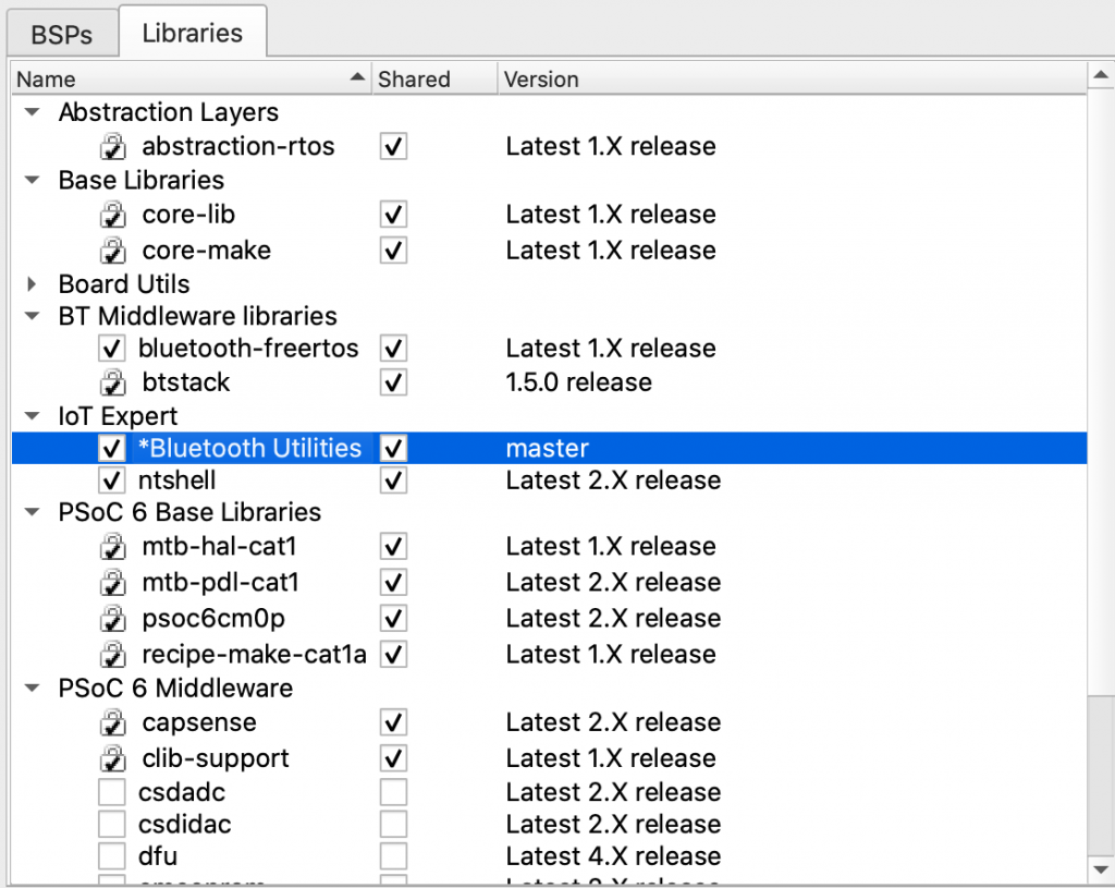
Add to the IoT Expert Manifest

In order to set it up for my library to live in the library manager I updated the IoT Expert Manifest file to have a link to the GitHub repository

<middleware>
<name>Bluetooth Utilities</name>
<id>btutil</id>
<uri>https://github.com/iotexpert/btutil</uri>
<desc>A library of Bluetooth Debugging Utilties for Cypress PSoC6 Anycloud</desc>
<category>IoT Expert</category>
<req_capabilities>psoc6</req_capabilities>
<versions>
<version flow_version="1.0,2.0">
<num>master</num>
<commit>master</commit>
<desc>master</desc>
</version>
</versions>
</middleware>

And now the library manager has the IoT Expert Bluetooth Utilities.


CY8CKIT-028-EPD Better Timing

Summary

In the first article of this series I talked about how to make the CY8CKIT-028-EPD EINK Shield work with PSoC 6 and Modus Toolbox 1.1. In the second article I improved the interface and talked about the PSoC 6 clocking system.  In this article I want to address the timing system in the EINK firmware.  You might recall that I used one of the Timer-Counter-Pulse-Width-Modulator blocks a.k.a the TCPWM inside of the PSoC 6 as a Timer for updating the EINK Screen.  Using this timer was a bit of a waste as the CM4 already has a timer built into the device called the SysTick timer.  Moreover, the SysTick timer is connected to the FreeRTOS timing system which provides you APIs to talk to it.  For this article I will talk about:

  • ARM SysTick
  • Cypress PDL and SysTick
  • FreeRTOS and SysTick
  • Make a new project & copy the files
  • Use the FreeRTOS timing system to measure the speed increase of the updated SPI
  • Remove the hardware timer & replace with the RTOS timer.

ARM SysTick

The ARM Cortex-M MCUs have an option to include a 24-bit timer called SysTick.  As best I can tell, every MCU maker always chooses to have the SysTick option built in.   Certainly the PSoC 4 and PSoC 6 family all have it built in.   But how do you talk to it?  Well, my buddy Reinhard Keil decided that it was silly for everyone to create a different method for interacting with standard ARM peripherals so he created the Cortex Microcontroller Software Interface Standard (CMSIS)

CMSIS defines two things that you need to do to make the SysTick timer work.  First, you need to create a function called EXACTLY “SysTick_Handler”.  This function gets loaded into the vector table of your program as the interrupt handler for the SysTick interrupt.  As such the function prototype is “void SysTick_Handler(void)”.  The second thing that you need to do is initialize how often the timer should be called.  You do this with the CMSIS call:

SysTick_Config(SystemCoreClock/1000);

It is interesting to note that the symbol SystemCoreClock is also defined by CMSIS as the frequency of the clock.  So the above call would setup the SysTick to be called every 1Ms (that is why there is a divide by 1000).

Here is an example I created starting with the BlinkyLED example project.  After I created the project, I added the kitprog uart (which is SCB5) and I added the Retarget I/O middleware.

#include "cy_pdl.h"
#include "cycfg.h"
#include <stdio.h>
volatile uint32_t count;
void SysTick_Handler(void)
{
count += 1;
}
cy_stc_scb_uart_context_t kitprog_context;
int main(void)
{
Cy_SCB_UART_Init(kitprog_HW,&kitprog_config,&kitprog_context);
Cy_SCB_UART_Enable(kitprog_HW);
/* Set up internal routing, pins, and clock-to-peripheral connections */
init_cycfg_all();
SysTick_Config(SystemCoreClock/1000);
/* enable interrupts */
__enable_irq();
for (;;)
{
printf("Test count=%d\n",(int)count);
Cy_GPIO_Inv(LED_RED_PORT, LED_RED_PIN); /* toggle the pin */
Cy_SysLib_Delay(1000/*msec*/);
}
}

Don’t forget to setup the standard i/o by modifying stdio_user.h

#include "cycfg.h"
/* Must remain uncommented to use this utility */
#define IO_STDOUT_ENABLE
#define IO_STDIN_ENABLE
#define IO_STDOUT_UART      kitprog_HW
#define IO_STDIN_UART       kitprog_HW

When you run the program above you should get something like this:

One interesting question is HOW does the function SysTick_Handler get into the vector table?  Well if you run an eclipse search (type ctrl-h)

You will find it in an assembly language file called “startup_psoc6_01_cm4.s”

Double click on the file and you can see the Vector table.

__Vectors:
.long    __StackTop            /* Top of Stack */
.long    Reset_Handler         /* Reset Handler */
.long    CY_NMI_HANLDER_ADDR   /* NMI Handler */
.long    HardFault_Handler     /* Hard Fault Handler */
.long    MemManage_Handler     /* MPU Fault Handler */
.long    BusFault_Handler      /* Bus Fault Handler */
.long    UsageFault_Handler    /* Usage Fault Handler */
.long    0                     /* Reserved */
.long    SVC_Handler           /* SVCall Handler */
.long    DebugMon_Handler      /* Debug Monitor Handler */
.long    0                     /* Reserved */
.long    PendSV_Handler        /* PendSV Handler */
.long    SysTick_Handler       /* SysTick Handler */

But how do the _Vectors get into the right place?  Well? run the search again and you will find that the linker script (which Cypress created) for your project has the definition.

When you look in the linker script you can see that it is installed at the top of the flash

    {
. = ALIGN(4);
__Vectors = . ;
KEEP(*(.vectors))
. = ALIGN(4);
__Vectors_End = .;
__Vectors_Size = __Vectors_End - __Vectors;
__end__ = .;
. = ALIGN(4);
*(.text*)
KEEP(*(.init))
KEEP(*(.fini))
/* .ctors */
*crtbegin.o(.ctors)
*crtbegin?.o(.ctors)
*(EXCLUDE_FILE(*crtend?.o *crtend.o) .ctors)
*(SORT(.ctors.*))
*(.ctors)
/* .dtors */
*crtbegin.o(.dtors)
*crtbegin?.o(.dtors)
*(EXCLUDE_FILE(*crtend?.o *crtend.o) .dtors)
*(SORT(.dtors.*))
*(.dtors)
/* Read-only code (constants). */
*(.rodata .rodata.* .constdata .constdata.* .conststring .conststring.*)
KEEP(*(.eh_frame*))
} > flash

And the CM4 flash is defined to start at 0x100002000

MEMORY
{
/* The ram and flash regions control RAM and flash memory allocation for the CM4 core.
* You can change the memory allocation by editing the 'ram' and 'flash' regions.
* Note that 2 KB of RAM (at the end of the RAM section) are reserved for system use.
* Using this memory region for other purposes will lead to unexpected behavior.
* Your changes must be aligned with the corresponding memory regions for CM0+ core in 'xx_cm0plus.ld',
* where 'xx' is the device group; for example, 'cy8c6xx7_cm0plus.ld'.
*/
ram               (rwx)   : ORIGIN = 0x08002000, LENGTH = 0x45800
flash             (rx)    : ORIGIN = 0x10002000, LENGTH = 0xFE000
/* This is a 32K flash region used for EEPROM emulation. This region can also be used as the general purpose flash.
* You can assign sections to this memory region for only one of the cores.
* Note some middleware (e.g. BLE, Emulated EEPROM) can place their data into this memory region.
* Therefore, repurposing this memory region will prevent such middleware from operation.
*/
em_eeprom         (rx)    : ORIGIN = 0x14000000, LENGTH = 0x8000       /*  32 KB */
/* The following regions define device specific memory regions and must not be changed. */
sflash_user_data  (rx)    : ORIGIN = 0x16000800, LENGTH = 0x800        /* Supervisory flash: User data */
sflash_nar        (rx)    : ORIGIN = 0x16001A00, LENGTH = 0x200        /* Supervisory flash: Normal Access Restrictions (NAR) */
sflash_public_key (rx)    : ORIGIN = 0x16005A00, LENGTH = 0xC00        /* Supervisory flash: Public Key */
sflash_toc_2      (rx)    : ORIGIN = 0x16007C00, LENGTH = 0x200        /* Supervisory flash: Table of Content # 2 */
sflash_rtoc_2     (rx)    : ORIGIN = 0x16007E00, LENGTH = 0x200        /* Supervisory flash: Table of Content # 2 Copy */
xip               (rx)    : ORIGIN = 0x18000000, LENGTH = 0x8000000    /* 128 MB */
efuse             (r)     : ORIGIN = 0x90700000, LENGTH = 0x100000     /*   1 MB */
}

And when you look at the linker MAP file which is in your project Debug/BlinkyLED_mainapp.map you will see that the vectors end up in the right place.

.text           0x0000000010002000     0x5de4
0x0000000010002000                . = ALIGN (0x4)
0x0000000010002000                __Vectors = .

Cypress SysTick

Now if you happen to be reading the PDL documentation on Saturday afternoon you might notice that there is a section of the documentation called “SysTick”.  And when you click it you will find this:

And you might ask yourself “What the hell.. those aren’t CMSIS functions?”  Well in typical Cypress fashion we created an extension to SystTick.  It does two basic things

  1. Lets you pick different clock sources for the SysTick timer
  2. Lets you setup multiple callbacks to make it easier to trigger multiple functions in your system

For this example I modified the previous project by commenting out the CMSIS calls.  And I use the Cy_SysTick calls.

#include "cy_pdl.h"
#include "cycfg.h"
#include <stdio.h>
volatile uint32_t count;
cy_stc_scb_uart_context_t kitprog_context;
#if 0
void SysTick_Handler(void)
{
count += 1;
}
#endif
void MyHander(void)
{
count += 1;
}
int main(void)
{
Cy_SCB_UART_Init(kitprog_HW,&kitprog_config,&kitprog_context);
Cy_SCB_UART_Enable(kitprog_HW);
/* Set up internal routing, pins, and clock-to-peripheral connections */
init_cycfg_all();
Cy_SysTick_Init ( CY_SYSTICK_CLOCK_SOURCE_CLK_CPU, 100000000/1000); // CPU Freq divide by 1000 makes MS
Cy_SysTick_SetCallback(0,MyHander); // Slot 0
Cy_SysTick_Enable();
//    SysTick_Config(SystemCoreClock/1000);
/* enable interrupts */
__enable_irq();
for (;;)
{
printf("Test count=%d\n",(int)count);
Cy_GPIO_Inv(LED_RED_PORT, LED_RED_PIN); /* toggle the pin */
Cy_SysLib_Delay(1000/*msec*/);
}
}

When you look at this program you might ask where I got the “100000000/1000″…. and if Hassane is reading he will ask WHY DIDN’T YOU COMMENT IT.   The answer to the first question is that it is the CPU Frequency divided by 1000 to get a millisecond timer.

As to the second question… the answer is … “I just did” 🙂

There is probably some MACRO for those values… but I just don’t know what they are… and I suppose that I should go look… but…

And finally the “// slot 0”  means that it uses the first of 5 slots… in other words places where you can store a callback.

FreeRTOS usage of SysTick

The FreeRTOS by default uses the SysTick timer to cause the scheduler to run.  And it does this by using the CMSIS interface… well because everyone needs to do their own thing, it actually lets you define the function.  Here is a clip out of FreeRTOSConfig.h where it defines the actual function name as xPortSysTickHandler.

/* Definitions that map the FreeRTOS port interrupt handlers to their CMSIS
standard names - or at least those used in the unmodified vector table. */
#define vPortSVCHandler     SVC_Handler
#define xPortPendSVHandler  PendSV_Handler
#define xPortSysTickHandler SysTick_Handler

And when you look around (using find) you will find it in the file port.c.

void xPortSysTickHandler( void )
{
/* The SysTick runs at the lowest interrupt priority, so when this interrupt
executes all interrupts must be unmasked.  There is therefore no need to
save and then restore the interrupt mask value as its value is already
known. */
portDISABLE_INTERRUPTS();
{
/* Increment the RTOS tick. */
if( xTaskIncrementTick() != pdFALSE )
{
/* A context switch is required.  Context switching is performed in
the PendSV interrupt.  Pend the PendSV interrupt. */
portNVIC_INT_CTRL_REG = portNVIC_PENDSVSET_BIT;
}
}
portENABLE_INTERRUPTS();
}

And if you look in vTaskStartScheduler you will find that it calls the function vPortSetupTimerInterrupt where it sets up interrupt manually.

/*
* Setup the systick timer to generate the tick interrupts at the required
* frequency.
*/
__attribute__(( weak )) void vPortSetupTimerInterrupt( void )
{
/* Calculate the constants required to configure the tick interrupt. */
#if( configUSE_TICKLESS_IDLE == 1 )
{
ulTimerCountsForOneTick = ( configSYSTICK_CLOCK_HZ / configTICK_RATE_HZ );
xMaximumPossibleSuppressedTicks = portMAX_24_BIT_NUMBER / ulTimerCountsForOneTick;
ulStoppedTimerCompensation = portMISSED_COUNTS_FACTOR / ( configCPU_CLOCK_HZ / configSYSTICK_CLOCK_HZ );
}
#endif /* configUSE_TICKLESS_IDLE */
/* Stop and clear the SysTick. */
portNVIC_SYSTICK_CTRL_REG = 0UL;
portNVIC_SYSTICK_CURRENT_VALUE_REG = 0UL;
/* Configure SysTick to interrupt at the requested rate. */
portNVIC_SYSTICK_LOAD_REG = ( configSYSTICK_CLOCK_HZ / configTICK_RATE_HZ ) - 1UL;
portNVIC_SYSTICK_CTRL_REG = ( portNVIC_SYSTICK_CLK_BIT | portNVIC_SYSTICK_INT_BIT | portNVIC_SYSTICK_ENABLE_BIT );
}

And what is really cool is that when you look in FreeRTOSConfig.h you can see that it uses the CMSIS macro “SystemCoreClock” and that it is configured to have a 1MS callback.

#define configCPU_CLOCK_HZ                      SystemCoreClock
#define configTICK_RATE_HZ                      1000u

So, why did I look at all of that?  Well simple, each time that the SysTick interrupt is called, the FreeRTOS adds 1 to a count…. which you can get access to by calling “xTaskGetTickCount”.  Nice.

I think that is enough background… so let’s:

Make a New Project

I want to start by creating a copy of the project from the previous article (so that alls yall can see the progression of code changes).  In the previous article I walked you step-by-step through creating and copying a project.  Here is a summary of the step you need to take.  If you want to see the details please look at the last article.

  1. Make a new project
  2. Copy design.modus
  3. Add the middleware (FreeRTOS, Segger Core OS NoTouch & Soft FP,Segger BitPlains, Retarget I/O)
  4. Copy all of the files from the source directory
  5. Update the Include paths with the “eInk Library” and “emWin_Config”

After making all of these changes I will have a project in my workspace called “EHKEinkTiming”.  I would recommend before you go further that you build and program to make sure that everything is still working.

Measure the SPI Speed Increase

All of the action to dump the frame buffer onto the EINK display happens in the function UpdateDisplay in the file eInkTask.c.  In the code below you can see that I ask FreeRTOS what the count is before I dump the display, then what the count is after it is done.

void UpdateDisplay(cy_eink_update_t updateMethod, bool powerCycle)
{
/* Copy the EmWin display buffer to imageBuffer*/
LCD_CopyDisplayBuffer(imageBuffer, CY_EINK_FRAME_SIZE);
uint32_t startCount = xTaskGetTickCount();
/* Update the EInk display */
Cy_EINK_ShowFrame(imageBufferCache, imageBuffer, updateMethod, powerCycle);
uint32_t endCount = xTaskGetTickCount();
printf("Update Display Time = %d\n",(int)(endCount - startCount));
/* Copy the EmWin display buffer to the imageBuffer cache*/
LCD_CopyDisplayBuffer(imageBufferCache, CY_EINK_FRAME_SIZE);
}

When I run the updated program I find that it takes about 1.7 seconds to update the screen.

Then I go back and modify the original program (before the SPI fixes) to see how long it takes…

And yes if you can do math, which I’m sure everyone who has read this far can, you will notice that I only sped things up by 65 Milliseconds… which means you need to call bullshit on my original declaration that it was noticeably faster.  Oh well at least I learned a bunch about the clock system.

Remove the HW timer & Update the EINK Driver

OK now that we have the hang of SysTick, it is clear that we don’t need the hardware timer that we put into the first project, so let’s get it out of there.  Start by running design.modus and removing the timer.  Just click the checkbox on “TCPWM[1]…” to turn it off.  Then press save.

If you hit compile you will find a whole bunch of errors… but they are all in four functions inside of cy_eink_psoc_interface.c.   Specifically

  • Cy_EINK_TimerInit
  • Cy_EINK_GetTimeTick
  • Cy_EINK_TimerStop

To fix them Ill first create a global static variable called “timerCount”

static uint32_t timerCount;

Then update Cy_EINK_TimerInit to just store the current FreeRTOS timer value in my new global variable.

void Cy_EINK_TimerInit(void)
{   
timerCount = xTaskGetTickCount();
}

Next update Cy_EINK_GetTimeTick to return the number of ticks since the timer was initialized.

uint32_t Cy_EINK_GetTimeTick(void)
{
/* Return the current value of time tick */
return(xTaskGetTickCount()-timerCount);
}

Finally, make the TimerStop function do… well… nothing.

void Cy_EINK_TimerStop(void)
{
}

When I build and program… my project is off to the races without the hardware timer.

In the next article Ill have a look at the EINK datasheet and driver to look into how it works.

CY8CKIT-028-EPD and Modus Toolbox 1.1

Summary

One of my very influential readers is working on a project where he wants to use the CY8CKIT-028-EPD.  But, he wants to use Modus Toolbox 1.1 instead of PSoC Creator and he observed, correctly, that Cypress doesn’t have a MTB code example project for the CY8CKIT-028-EPD.  I knew that we had a working code example in PSoC Creator (CE223727), so I decided to do a port to MTB1.1.  This turned out to be a bit of an adventure which required me to dig out a logic analyzer to solve self inflicted problems.  Here is a picture I took while sorting it out.

There are a few things in the PSoC Creator example code which I didn’t really like, so, for the final solution, I would like it to be

  • In Modus Toolbox 1.1
  • Using FreeRTOS
  • Using the Segger emWin graphics library
  • Getting the best response time
  • Using DMA to drive the display

For this article I will go through these steps:

  1. Build CE223727 EmWin_Eink_Display in PSoC Creator
  2. Explain the PSoC Creator Project
  3. Create a new MTB Project & add the FreeRTOS, Segger emWin and stdio middleware
  4. Configure the device for the correct pins, clocks and peripherals
  5. Setup FreeRTOS and Standard I/O
  6. Copy the driver files into the MTB project from the PSoC Creator workspace
  7. Port the drivers and eInkTask to work in MTB
  8. Program and Test
  9. (Part 2) Update the driver to remove the hardware timer
  10. (Part 2) Update the example to remove polled switch and use a semaphore
  11. (Part 2) Update the driver to use DMA
  12. (Part 2) Explain how the EINK EPD Display Works

If you lack patience and you just want a working project, you can download it from the IoT Expert GitHub site. git@github.com:iotexpert/eink-emwin-mtb1-1.git

First build CE223727 EmWin_Eink_Display in PSoC Creator

Start by finding the code example project for the Eink Display.  In PSoC Creator on the File->Code Example menu you will be able to pick out the code example.

There are a bunch of code examples, so the easiest way to find them is the filter based on “emwin”.  I did this because I knew we had used the Segger emWin Graphics library.  Notice in the picture below there are two emWin examples.  One with a “world” beside it and one without.  The world symbol means that it is on the internet and you will need to download it.  You can do that by clicking the world button.  Probably, you will find that your CE223727 EmWin_EInk_Display will have a world beside it and you will need to download it before you can make the project.

Once you click create project it will ask you about the project.  Just click “next”

Then give your project (and workspace) a name.  I called the workspace “EPDExample” and the project “CE22….”

After all of that is done you will have a schematic (and all of the other stuff required for the project).

When you click the program button it will ask you which MCU target to program (pick either, it doesnt matter)

After a while, your console window should look like this.

And you development kit should do its thing.

Explain the PSoC Creator Project

Now, lets have a look at the project.  Starting on the upper left hand part of the schematic you find that the interface to the EPD is via a SPI.  The SPI slave select is controlled with the Pervasive driver firmware rather than letting the SPI block directly control it.

The SPI is configured to be 16 megabits per second with CPHA=0 and CPOL=0.

I didn’t notice this at first, but in the picture above you can see that the actual speed of the SPI is 8.33 mbs.  That isn’t 16mbs for sure.  But why the gap?  The first thing to know is that in order for the SPI block to work correctly the input clock must be set at the desired datarate times the oversample.  What is oversample?  That is a scheme to get rid of glitchy-ness in the input signal.  In this case it will take 6 input samples to determine if the input is a 1 or a 0.  (median filter I think).  With this configuration the input clock to the SCB needs to be 16mbs * 6 = 96mhz.

But what is the input clock frequency?  If you click on the dwr->clocks you will see this screen which shows that the input clock is 50Mhz (the last line highlighted in blue).  Further more you can see that the source clock for the SCB is “Clk_Peri”.  When you divide 50mhz source clock rate by 6 oversample you will find that the actual bitrate is 8.33kbs.

But where does the 50mhz come from?  Well, the clock system is driven by the “IMO”.  IMO stands for internal main oscillator and it is a trimmed RC oscillator built into the chip. (thanks Tim).  This oscillator runs into an FLL which up converts it to 100MHz.

That signal is then run into the “Clk_Peri” divider which divides it by two to yield a clock of 50MHz.  Which is not all that close to 96MHz… and means that our SPI runs at the wrong speed.

But what does the EPD driver chip actually want?  You can find the documentation for this EPD on the Pervasive website.  That web page also has a link to the Product Specification 2.7″ TFT EPD Panel (E2271CS021) Rev.01 as well as the driver chip COG Driver Interface Timing for small size G2 V231

When you look in the timing document you will find that the actual chip can take up to a 20Mhz input clock.  This means that our code example actually updates the screen at 42% (8.33/20) of what it could.  That gives us a chance to make things faster… which I will do after the port to MTB.

The next sectin of the schematic has a TCPWM that is configured as a timer.  This has an input clock of 2kHz.


And is setup to divide by 2 which will yield a counter that updates every 1ms.  The author of this code example used the TCPWM to time operations inside of the driver (which I will also replace with something better)

Lastly there are some GPIOs that control various control pins on the display.  I don’t really know what all of the pins do, but will sort it out in the next article.

And all of the pins are assigned like this:

Create a new MTB project & Add the Middleware

It is time to start the project in MTB.  Start up Modus Toolbox 1.1 and select File->New->ModusToobox IDE Application    

Then select the CY8CKIT-062-BLE Development Kit.  This kit comes with the CY8CKIT-028-EPD EINK Shield that you can see in the pictures above.

I decide to call my project “EHKEink” and I derive my project from the “EmptyPSoC6App” template.

Once that is done, Let it rip.

And you should end up with a screen that looks like this. On the left in the workspace explorer you see the main app project.  In the middle you see the readme file which explains how this project is configured.

The next step is to add the “Middleware” that we need to make this project work.  You can do this by clicking the select Middleware button from the ModusToolbox quick panel.

For this project we need

  • FreeRTOS
  • Retarget I/O
  • Segger emWin Core, OS, no Touch, Soft FP
  • Segger emWin display driver BitPlains

The middleware selector will bring in all of the drivers you selected into your project.  You can see that it also adds the FreeRTOS configuration file “FreeRTOSConfig.h” as well as “stdio_user.c” etc.  These files endup in the source folder and are for you to edit.

While I was working on this, I found a bug in the emWin middleware, specifically the the configuration files for BitPlains get included twice.  To fix this you need to change the project properties and remove the path to “..components/psoc6mw/emWin/code/drivers/BitPlains/config”.  To do this, select the project in the workspace explorer then right click and select properties.

Then select “C/C++ General –> Paths and Symbols”.  Select the “…BitPlains/config” path and click “Delete”

Configure the device in MTB

Modus Toolbox does not have a “schematic” or a “dwr” like PSoC Creator.  In order to achieve the same functionality we built the “Configurator”.  This tool will let you setup all of the peripherals in your project.  To run it select “Configure Device” in the MTB Quick Panel.

Remember from the PSoC Creator Schematic we need to have:

  • A bunch of pins
  • A SPI
  • A Timer
  • Plus I want a UART to connect to standard I/O.

First, click on the “Pins” tab.  This lets you set all of the configuration information for each of the pins on the chip.  I will go one by one enabling the pins and setting them as digital inputs or output.  I am going to give all of the pins that exact same names that they had in the PSoC Creator Project because I know the author of that project used PDL.  When you give a pin a name in the configurator it will generate #defines or c structures based on the name.  This will make the source code the original PSoC Creator author wrote almost exactly compatible with MTB.

Here is an example of the first output pin which is P0[2] and is named CY_EINK_DispIoEn.  For the output pins you need to do four things.

  1. Enable the checkbox next to the pin name. (in this case P0[2])
  2. Give the pin a name (CY_EINK_DispIoEn)
  3. Set the drive mode (Strong Drive, Input buffer off)
  4. Set the initial state of the pin (High (1))

Now, you need to go one by one turning on all of the output pins (Im not showing you screen shots of all of them)

There are two input pins for this project SW2 P0[4] and CY_EINK_DispBusy P5[3].  For these pins I will:

  1. Enable the pin checkbox
  2. Give the pin a name (in this case SW2)
  3. Resistive Pull-Up, Input buffer on.  Note for P5[3] the pullup resistor is not needed

Now that the digital pins are configured, you can setup the STDIO Uart.  This will be used to send debugging messages to the console Uart which is attached to your computer via a USB<->UART bridge in KitProg 3.

Start by enabling SCB5 and giving it the name “UART”.  Make sure that the baud rate is set to 115200 and the rest to 8n1

Scroll down the window and pick out the RX and TX Pins plus the clock (any of the 8-bit clock dividers will do.  In this case I chose Divider 0)

Now, you need to setup the SPI.  To do this turn on SCB 6, set it to SPI, give it the name “CY_EINK_SPIM”, set it to “Master”, fix the data rate to 1000

Then scroll down to the “Connections” section and assign the pins

The last bit of hardware we need is a timer with a 1000kHz input clock, in other words a millisecond timer.  To do this start by enabling TCPWM[1] 16-bit counter.  Call it “CY_EINK_Timer” which was the same name as the PSoC Creator project.  Then setup

  • As a “Timer Counter”.
  • One shot
  • Up count
  • Period is 65535 (aka the max)
  • And pick “Clock signal” as 16 bit Divider

Given that we want it to count milliseconds and the input has a 128 bit pre-divider… we need for the input clock to be setup to 128khz.  Click on “Peripheral clocks” then select “16 Bit Divider 0”.  Notice that the input frequency is 72Mhz and we need 128Khz… to get this a divider of 562 is required.  72mhz/128khz = 562

Setup FreeRTOS and Standard I/O

The next step is to setup the “plumbing”.  In this projet we are using FreeRTOS and Standard I/O. To configure FreeRTOS just edit the “FreeRTOSConfig.h” and remove the “warning”

#warning This is a template. Modify it according to your project and remove this line. 

Enable mutexes on line 57

#define configUSE_MUTEXES                       1

Make the heap bigger on line 70

#define configTOTAL_HEAP_SIZE                   1024*48

Change the memory scheme to 4 on line 194

#define configHEAP_ALLOCATION_SCHEME                (HEAP_ALLOCATION_TYPE4)

To enable the UART to be used for Standard I/O, edit “stdio_user.h” and add the includes for “cycfg.h”.  Then update the output and input Uart to be “UART_HW” (which is the name you gave it in the configurator)

#include "cycfg.h"
/* Must remain uncommented to use this utility */
#define IO_STDOUT_ENABLE
#define IO_STDIN_ENABLE
#define IO_STDOUT_UART      UART_HW
#define IO_STDIN_UART       UART_HW

Now make a few edits to main.c to

  • Add includes for the configuration, rtos and standard i/o
  • Create a context for the UART
  • Create a blinking LED Task
  • In main start the UART and start the blinking LED task.
#include "cy_device_headers.h"
#include "cycfg.h"
#include "FreeRTOS.h"
#include "task.h"
#include <stdio.h>
cy_stc_scb_uart_context_t UART_context;
void blinkTask(void *arg)
{
(void)arg;
for(;;)
{
vTaskDelay(500);
Cy_GPIO_Inv(LED_RED_PORT,LED_RED_PIN);
printf("blink\n");
}
}
int main(void)
{
init_cycfg_all();
__enable_irq();
Cy_SCB_UART_Init(UART_HW,&UART_config,&UART_context);
Cy_SCB_UART_Enable(UART_HW);
xTaskCreate( blinkTask,"blinkTask", configMINIMAL_STACK_SIZE,  0,  1, 0  );
vTaskStartScheduler();
while(1);// Will never get here
}

As I edited the code I notice that it can’t find “LED_RED” which made me realize that I forgot to add the LED_RED attached to P0[3] in the configuration.  So, I go back and update P0[3] to be LED_RED as strong drive digital output.

Finally just to make sure that it is all working lets program the kit.  When I press “EHKEink Program” form the quickpanel…

I get this message in the console.

But how can that be?  I have my kit plugged in?  In order to program your kit using Modus you need “KitProg3”.  PSoC Creator can program you kit with KitProg3 only if it is in the CMSIS-DAP HID mode.  To switch you development kit to KitProg3, you can use the program “fw-loader” which comes with MTB.  You can see what firmware you have by running “fw-loader –device-list”.  To change to KitProg 2 run “fw-loader –update-kp2” and to update to KitProg3 run “fw-loader –update-kp3”

Now when i program I get both the LED blinking and the console printing blink.

Copy the files into the MTB project

Next, I want to bring over the drivers from the PSoC Creator project.  They reside in folder called “eInk Library” inside of the PSoC Creator project.  You can copy them by navigating to the PSoC Creator workspace, then typing ctrl-c in the File Explorer, then clicking the “Source” directory in your Eclipse WorkSpace explorer and typing ctrl-v

You will also need the four files “GUIConf.c”, “GUIConf.h”, “LCDConf.h” and “LCDConf.c”.  Copy and paste them into the emWin_config directory.

For this project I am going to use the code that existed in “main.c” from the original PSoC Creator project.  But I want it to be a task (and a few other changes).  To facilitate things, I will copy it as well. Then rename it to eInkTask.c.  And finally, the file “Cypress Logo Full Color_png1bpp.c” needs to be copied as well.

After all of those copies you should have your project looking something like this:

Port the Drivers and eInkTask

Now we need to fix all of the driver code.  Big picture you will need to take the following actions.

  • Update the Project settings to include the new folders (emWin_config and emWin Library)
  • Replace the PSoC Creator #include <project.h> with MTB #include “cycfg.h”
  • Update the files to have #include “FreeRTOS.h” and “task.h” where appropriate
  • Replace all of the CyDelay’s with vTaskDelays
  • Fix the old PSoC Creator component calls for the timer with PDL calls

First go to the project settings (remember, click on the project then select properties).  Then pick “C/C++ Build Settings” then “GNU ARM Cross C Compiler” and “includes”  Press the little green “+” to add the new directories

You can select both directories at once.

Next edit  eInkTask.c

Update #include “project.h” to be #include “cycfg.h” on line 59.  Add “FreeRTOS.h” and “task.h” to the includes.

#include "cycfg.h"
#include "GUI.h"
#include "pervasive_eink_hardware_driver.h"
#include "cy_eink_library.h"
#include "LCDConf.h"
#include "FreeRTOS.h"
#include "task.h"
#include <stdio.h>

Find and replace “CyDelay” with “vTaskDelay”

Update the PSoC Creator component call  _Read with the pdl calls Cy_GPIO_Read on line 661

void WaitforSwitchPressAndRelease(void)
{
/* Wait for SW2 to be pressed */
while(Cy_GPIO_Read(SW2_PORT,SW2_PIN) != 0);
/* Wait for SW2 to be released */
while(Cy_GPIO_Read(SW2_PORT,SW2_PIN) == 0);
}

Update the “int main(void)” to be “void eInkTask(void *arg)” on line 687

void eInkTask(void *arg)
{
(void)arg;

Remove ” __enable_irq(); /* Enable global interrupts. */” from the old main on line 695.

In the file cy_eink_psoc_interface.h

Update the #include <project.h> to be #include “cycfg.h” on line 59.

In the file cy_eink_psoc_interface.c

Create a context for the SPIM by adding on line 58:

cy_stc_scb_spi_context_t CY_EINK_SPIM_context;

The three timer functions in this file use the old PSoC Creator component timer interface APIs rather than the PDL interface.  So you will need to change Cy_EINK_TimerInit, Cy_EINK_GetTimeTick and Cy_EINK_TimerStop to use PDL.

Here is Cy_EINK_TimerInit

void Cy_EINK_TimerInit(void)
{   
/* Clear the counter value and the counter variable */
//CY_EINK_Timer_SetCounter(0);
Cy_TCPWM_Counter_Init (CY_EINK_Timer_HW, CY_EINK_Timer_NUM, &CY_EINK_Timer_config);
Cy_TCPWM_Counter_SetCounter	(	CY_EINK_Timer_HW, CY_EINK_Timer_NUM,0);
Cy_TCPWM_Enable_Multiple(	CY_EINK_Timer_HW,CY_EINK_Timer_MASK);
/* Initialize the Timer */
//CY_EINK_Timer_Start();
Cy_TCPWM_TriggerStart	(	CY_EINK_Timer_HW,CY_EINK_Timer_MASK);
}

And Cy_EINK_GetTimeTick

uint32_t Cy_EINK_GetTimeTick(void)
{
/* Variable used to store the time tick */
uint32_t timingCount;
/* Read the current time tick from the E-INK Timer */
//timingCount = CY_EINK_Timer_GetCounter();
timingCount = Cy_TCPWM_Counter_GetCounter	(CY_EINK_Timer_HW, CY_EINK_Timer_NUM);
/* Return the current value of time tick */
return(timingCount);
}

And Cy_EINK_TimerStop

void Cy_EINK_TimerStop(void)
{
/* Stop the E-INK Timer */
//CY_EINK_Timer_Disable();
Cy_TCPWM_Counter_Disable(CY_EINK_Timer_HW, CY_EINK_Timer_NUM);
}

In  the file LCDConf.h change the include to stdint.h and make the type uint8_t instead of uint8

#include  <stdint.h>
void LCD_CopyDisplayBuffer(uint8_t * destination, int count);

In the file LCDConf.c remove the #include “syslib/cy_syslib.h” (I have no idea why it is/was there) and then add “#include <stdint.h>”  On line 219 change “uint8” to be “uint8_t”

void LCD_CopyDisplayBuffer(uint8_t * destination, int count)

In the file cy_eink_fonts.h change the “#include <project.h>” to be

#include <stdint.h>
#include <stdbool.h>

In main.c add an external reference to the eInkTask on line 36 (yes this is really ugly Alan)

extern void eInkTask(void *);

And start the eInkTask on line 58.  Notice that I put in 10K for the stacksize… but I dont actually know how much it takes.

  	xTaskCreate( eInkTask,"eInkTask", 1024*10,  0,  1, 0  );

Program & Test the MTB Project

When you program the development kit you should have

  1. A blinking RED LED
  2. The ability to scroll through a bunch of screens using the SW2 button.

Here is a picture

In the next article I will:

  1. Speed up the SPI
  2. Get rid of the hardware timer
  3. Explain more about the EINK.


PSoC 6 Introduction – Behind the Scenes

Summary

As you might have noticed, last week I did a bunch of work creating a live streaming video series about PSoC 6.  You can find the recorded video here.  If you have been living under a bridge you might not know that PSoC 6 is the new Cypress PSoC.  It includes a dual ARM Cortex M4/M0+, a Bluetooth Low Energy 5.0 Radio, CapSense plus all of the other stuff that PSoC is known for.  The chip is super cool and has gotten everybody and their brother excited about the future.

PSoC 6 Introduction

# Title Comment
0 A Two Hour PSoC 6 Class An introduction to the PSoC 6 class with links to all of the documents
1 Resources Links to all of the Cypress PSoC 6 information including videos, application notes etc.
2 Your First Project Learn how to build a PSoC 6 project and program your CY8CKIT-062-BLE development kit
3 FreeRTOS and a Debugging UART Build a project using FreeRTOS including a debug console with the UART
4 CapSense Build a project using the Mutual Cap Buttons and Self Cap Slider
5 Bluetooth Low Energy Build a CapSense project using BLE and CySmart

Since I did the webinar several things have happened

  1. Lesson 4: I fixed an error in the stack size for FreeRTOS
  2. Lesson 5: The PSoC Creator BLE PDL has been upgraded to greatly simplify the notifyCapSense function

All of the projects are available at git@github.com:iotexpert/psoc-6-introduction.git or www.github.com/iotexpert/psoc-6-introduction

You will be seeing a bunch more from me using the CY8CKIT-062-BLE development kits.

PSoC 6 Webinar

Here are some behind the scenes pictures that were taken the day before and the day of the recording session.

In the studio on Wednesday night… why doesnt it work?

Getting Ready for the PSoC 6 Webinar

Yes, Mouser was sponsoring the event… thank you very much!

PSoC 6 and Mouser

Getting things setup the morning of the recording session.

The morning of the PSoC 6 Video Webinar

During the presentation (Im sure whatever I was saying was important)

Talking about PSoC 6

Some video taken from behind the scenes.

The Gospel of PSoC 6

The whole crew.  Thank you very much to Mouser and ON24.

The whole crew for the PSoC 6 Webinar

Percepio Tracealyzer – Running on PSoC6

Summary

I have been having an excellent experience with Percepio Tracealyzer on PSoC4, so now, the next question is, “Will it work on PSoC6?”  The answer is yes, but it takes a few gyrations.  In the next two Articles I will show you how to use Tracealyzer on PSoC6 with:

  1. JLINK and Snapshot mode
  2. JLINK and Segger RTT in Streaming Mode
  3. A PSoC6 DMA –> UART Streaming Mode

In order to make these work you need to

  1. Make a new project and integrate the Trace Recorder Library
  2. Modify trcConfig.h
  3. Install the JLINK
  4. Build the project & test

Create a new PSoC6 project & Integrate the Trace Recorder Library

The process of integrating the TraceRecorder library is very similar to PSoC 4.  You need to add the include directories into your project.  Right click the project and pick “Build Settings…”

Click on the “Additional Include Directories”

Then add the two TraceRecorder include directory and the StreamPort include directory.

Next you should copy the configuration header files into your project so that you can edit them.  You can copy-paste them in Windows Explorer from “TraceRecorder/config” into your project

Next add the TraceRecoder .c and .h files into your project by right clicking “Add –>Existing Item..”

You need the .c and .h files from

  • yourproject/{trcConfig.h, trcSnapshotConfig.h, trcStreamingConfig.h}
  • TraceRecorder/*.c
  • TraceRecorder/include/*.h
  • TraceRecorder/streamports/Jlink_RTT/include/*.h
  • TraceRecorder/streamports/Jlink_RTT/*.c


Modify FreeRTOSConfig.h & trcConfig.h

The next step is to modify FreeRTOSConfig.h to include the trace recorder header.   Copy this block of code into the bottom for FreeRTOSConfig.h

#if ( configUSE_TRACE_FACILITY == 1 )
#include "trcRecorder.h"
#endif

Update the FreeRTOSConfig.h to turn on tracing.

#define configUSE_TRACE_FACILITY                1

Then modify trcConfig.h to include the CMSIS Core headers.

/******************************************************************************
* Include of processor header file
* 
* Here you may need to include the header file for your processor. This is 
* required at least for the ARM Cortex-M port, that uses the ARM CMSIS API.
* Try that in case of build problems. Otherwise, remove the #error line below.
*****************************************************************************/
//#error "Trace Recorder: Please include your processor's header file here and remove this line."
#include "cy8c6347bzi_bld53.h"

The first time that I did this, I tried just #include <project.h> but if you do that you will end up with hundreds of errors and hours and hours of trying to figure out what is going on.  It turns out that the FreeRTOS is picky about the order in which files are included.  And when PSoC Creator makes the project.h it assumes that the order of includes doesn’t matter.  I fixed this by just including the “cy8c6347bzi_bld53.h” header which just? has the CMSIS files.

After fixing that mess, I modify the trcConfig to specify that I am using a Cortex-M processor (actually two of them)

/*******************************************************************************
* Configuration Macro: TRC_CFG_HARDWARE_PORT
*
* Specify what hardware port to use (i.e., the "timestamping driver").
*
* All ARM Cortex-M MCUs are supported by "TRC_HARDWARE_PORT_ARM_Cortex_M".
* This port uses the DWT cycle counter for Cortex-M3/M4/M7 devices, which is
* available on most such devices. In case your device don't have DWT support,
* you will get an error message opening the trace. In that case, you may 
* force the recorder to use SysTick timestamping instead, using this define:
*
* #define TRC_CFG_ARM_CM_USE_SYSTICK
*
* For ARM Cortex-M0/M0+ devices, SysTick mode is used automatically.
*
* See trcHardwarePort.h for available ports and information on how to 
* define your own port, if not already present.
******************************************************************************/
//#define TRC_CFG_HARDWARE_PORT TRC_HARDWARE_PORT_NOT_SET
#define TRC_CFG_HARDWARE_PORT TRC_HARDWARE_PORT_ARM_Cortex_M

Ill start the project just using Snapshot mode

/*******************************************************************************
* Configuration Macro: TRC_CFG_RECORDER_MODE
*
* Specify what recording mode to use. Snapshot means that the data is saved in
* an internal RAM buffer, for later upload. Streaming means that the data is
* transferred continuously to the host PC. 
*
* For more information, see http://percepio.com/2016/10/05/rtos-tracing/
* and the Tracealyzer User Manual.
*
* Values:
* TRC_RECORDER_MODE_SNAPSHOT
* TRC_RECORDER_MODE_STREAMING
******************************************************************************/
#define TRC_CFG_RECORDER_MODE TRC_RECORDER_MODE_SNAPSHOT
//#define TRC_CFG_RECORDER_MODE TRC_RECORDER_MODE_STREAMING

To start the testing I created a really simple, single task blinked led program in main_cm4.c. The only thing that you have to add is the “vTraceEnable(TRC_START)” to turn on the TraceRecorder.

#include "project.h"
void ledTask(void *arg)
{
(void)arg;
while(1)
{
Cy_GPIO_Inv(RED_PORT,RED_NUM);
vTaskDelay(500);
}
}
int main(void)
{
__enable_irq(); /* Enable global interrupts. */
vTraceEnable(TRC_START);
xTaskCreate(ledTask,"LED Task",configMINIMAL_STACK_SIZE,0,1,0);
vTaskStartScheduler();
}

Testing Percepio Tracealyzer

To start with I setup snapshot mode.  I wasn’t sure exactly what the memory map was for the new PSoC6.  But I did know that PSoC Creator copied in a linker file (actually 3 linker files) and that if I looked in the file I would find the memory map.

When I opened the GCC linker file “cy8c6xx7_cm4_dual.ld” I found the memory map for the chip.

MEMORY
{
flash       (rx)    : ORIGIN = 0x10080000, LENGTH = 0x80000
wflash            (rx)    : ORIGIN = 0x14000000, LENGTH = 0x8000          /*  32 KB */
sflash_user_data  (rx)    : ORIGIN = 0x16000800, LENGTH = 0x800
sflash_nar        (rx)    : ORIGIN = 0x16001A00, LENGTH = 0x200
sflash_public_key (rx)    : ORIGIN = 0x16005A00, LENGTH = 0xC00
sflash_toc_2      (rx)    : ORIGIN = 0x16007C00, LENGTH = 0x400
xip               (rx)    : ORIGIN = 0x18000000, LENGTH = 0x8000000       /* 128 MB */
efuse             (r)     : ORIGIN = 0x90700000, LENGTH = 0x100000        /*   1 MB */
ram   (rwx) : ORIGIN = 0x08024000, LENGTH = 0x23800
}

To make read the Percepio Tracealyzer snapshot you need to select “JLink -> Read Trace (Snapshot)”.  When you do that, it asks you where the RAM is on that device.  I simply copy from the linker file the start and length of the RAM

After that I get the trace.

The next thing to do is modify the trcConfig.h to switch to streaming mode:

/*******************************************************************************
* Configuration Macro: TRC_CFG_RECORDER_MODE
*
* Specify what recording mode to use. Snapshot means that the data is saved in
* an internal RAM buffer, for later upload. Streaming means that the data is
* transferred continuously to the host PC. 
*
* For more information, see http://percepio.com/2016/10/05/rtos-tracing/
* and the Tracealyzer User Manual.
*
* Values:
* TRC_RECORDER_MODE_SNAPSHOT
* TRC_RECORDER_MODE_STREAMING
******************************************************************************/
//#define TRC_CFG_RECORDER_MODE TRC_RECORDER_MODE_SNAPSHOT
#define TRC_CFG_RECORDER_MODE TRC_RECORDER_MODE_STREAMING

After I reprogram my CY8CKIT-062 BLE, then “File->Connect to Target System” I end up with a nice stream of data.

And when I look at the stream it says that things are working just as expected.

Im not sure what its next.  Maybe I will make a DMA/UART version so as not to require the JLKINK.

As always you can find all of these projects on the IotExpert GitHub site or git@github.com:iotexpert/PSoC-Tracelyzer.git

Article Description
Percepio Tracealyzer & PSoC An Introduction to Percepio Tracealyzer on the Cypress PSoC
Percepio Tracealyzer RTT Streamport - PSoC4200M Make the JLINK RTT Library work with Tracealyzer
Percepio Tracealyzer PSoC UART Streamport Creating a UART Streamport
Percepio Tracealyzer - Analyzing the PSoC Tracealyzer Streamport Figure out what is broken in the UART Streamport
Percepio Tracealyzer - Using PSoC DMA to Fix the UART Streamport Implementing PSoC DMA to improve the CPU Utilization
Percepio Tracealyzer - Running on PSoC6 Porting the Percepio Tracealyzer to PSoC6

PSoC 6 FreeRTOS – The First Example

Summary

In the previous article(s) I have been writing about using FreeRTOS on PSoC 4 development kits.  The other day a friend of mine in Kentucky sent me a note asking about PSoC6, so here it is.  PSoC 6.  In this article I will write about the first PSoC 6 FreeRTOS example, obviously, the blinking LED.  In this article I will also get to show off the Type-C connector on the new CY8CKIT-062-BLE Devkit.

Create PSoC 6 FreeRTOS Project

To get this whole thing going, create a new PSoC 6 project in PSoC Creator.  Because the PSoC 6 is still in early release, you will need the secret key to get it going in PSoC6 Creator (which you can find out from the Early Access Program).  But, when you know the key, you will get something that we have all been waiting for, the ability to create a PSoC 6 project.

Once you have a new project (which I already renamed 1-LEDBlink) you can look at it in the Workspace Explorer where you will see the normal PSoC things, Schematic, Pins, Analog, etc.  So far, so good.

Next I click on then TopDesign.sch, then add a digital output pin.  That looks and feels familiar to all of you PSoC people out there.

Next I assign the pin to “P0[3]” on the Pins tab.  Wow, that tiny little CSP has a boatload of pins, and yes this chip can do a bunch of things.

Now for some new stuff.  I want to have FreeRTOS included in my project.  In the PSoC 4 family you need to download it, add paths to your project etc. Read about it here.  Instead of doing that, you can edit the “Build Settings” by right clicking on the project.

Then on the build settings menu, pick Peripheral Driver Library (more on this later).  On the PDL screen you can click to add “FreeRTOS” and you can pick out the memory management scheme (in this case I picked heap_4).

When you generate application, PSoC Creator will copy FreeRTOS into your project generated source, and give you a default FreeRTOSConfig.h (see it in the Header Files for the CM4)

PSoC Creator gives you a pretty generic FreeRTOSConfig.h file, with some of stuff hooked up (like the clock frequency).  This file is copied into your project.  Once that is done, you own it, and all of the changes to it.

#include "cy_device_headers.h"
#define configUSE_PREEMPTION                    1
#define configUSE_PORT_OPTIMISED_TASK_SELECTION 0
#define configUSE_TICKLESS_IDLE                 0
#define configCPU_CLOCK_HZ                      cy_delayFreqHz
#define configTICK_RATE_HZ                      1000u
#define configMAX_PRIORITIES                    7
#define configMINIMAL_STACK_SIZE                128
#define configMAX_TASK_NAME_LEN                 16
#define configUSE_16_BIT_TICKS                  0
#define configIDLE_SHOULD_YIELD                 1
#define configUSE_TASK_NOTIFICATIONS            1
#define configUSE_MUTEXES                       0
#define configUSE_RECURSIVE_MUTEXES             0
#define configUSE_COUNTING_SEMAPHORES           0
#define configQUEUE_REGISTRY_SIZE               10
#define configUSE_QUEUE_SETS                    0
#define configUSE_TIME_SLICING                  0
#define configUSE_NEWLIB_REENTRANT              0
#define configENABLE_BACKWARD_COMPATIBILITY     0
#define configNUM_THREAD_LOCAL_STORAGE_POINTERS 5
/* Memory allocation related definitions. */
#define configSUPPORT_STATIC_ALLOCATION         0
#define configSUPPORT_DYNAMIC_ALLOCATION        1
#define configTOTAL_HEAP_SIZE                   10240

The other thing that Creator does is hookup the necessary interrupt vectors (so that FreeRTOS will run)

/* Definitions that map the FreeRTOS port interrupt handlers to their CMSIS
standard names - or at least those used in the unmodified vector table. */
#define vPortSVCHandler     SVC_Handler
#define xPortPendSVHandler  PendSV_Handler
#define xPortSysTickHandler SysTick_Handler

Now you have a project setup, and template files for everything… including the CM0p.  After the chip turns on and the boot sequence is complete, it jumps to the main in the file main_cm0p.c.  That default version of that file just turns on the CM4.

/* ========================================
*
* Copyright YOUR COMPANY, THE YEAR
* All Rights Reserved
* UNPUBLISHED, LICENSED SOFTWARE.
*
* CONFIDENTIAL AND PROPRIETARY INFORMATION
* WHICH IS THE PROPERTY OF your company.
*
* ========================================
*/
#include "project.h"
int main(void)
{
__enable_irq(); /* Enable global interrupts. */
/* Enable CM4.  CY_CORTEX_M4_APPL_ADDR must be updated if CM4 memory layout is changed. */
Cy_SysEnableCM4(CY_CORTEX_M4_APPL_ADDR); 
/* Place your initialization/startup code here (e.g. MyInst_Start()) */
for(;;)
{
/* Place your application code here. */
}
}
/* [] END OF FILE */

Finally, the file main_cm4.c contains your program.

On lines 3-6 I just create a function which locks the MCU if there is a memory allocation failure inside of the FreeRTOS.

Lines 8-17 is a FreeRTOS task to blink the LED.  Notice that the old PSoC 4 functions pin_Write() and pin_Read() are now replaced with PDL versions of those functions.

Lastly, lines 23-24 create the LED task and launch the RTOS.

#include <project.h>
void vApplicationStackOverflowHook(TaskHandle_t *pxTask, signed char *pcTaskName )
{
while(1);
}
void ledTask(void *arg)
{
(void)arg;
while(1)
{
Cy_GPIO_Write(RED_PORT,RED_NUM,!Cy_GPIO_ReadOut(RED_PORT,RED_NUM));
vTaskDelay(500);
}
}
int main(void)
{
__enable_irq(); /* Enable global interrupts. */
xTaskCreate( ledTask, "LED Task",400,0,1,0);
vTaskStartScheduler();
while(1);
}

Program PSoC 6 FreeRTOS Project

Now that we have firmware.  It is time to program the devkit.  One thing that I think is cool is that the devkit is the first (of ours) to have Type-C on the devkit (I wonder if it is the first in the Industry?).  We provide a Type-A to Type-C cable so you can keep rolling if you haven’t switched over to Type-C, but as I have a new Mac with only Type-C ,I use a Type-C to Type-C cable.PSoC 6 Type-C

When you click program, PSoC Creator brings up the window asking you which core is the debug target.  In this case it doesn’t matter as you are programming a hex file with both the CM0+ and the CM4 code in it (remember they are shared memory).  So, I pick CM4 and let it rip.

Program PSoC 6 FreeRTOS Project

It is alive!  Amazing a dual core CM4/CM0 PSoC 6 FreeRTOS can blink the LED… how cool is that? PSoC6 FreeRTOS Blinking LED

In the next several articles I will be switching back and forth between the PSoC 4 & PSoC 6 FreeRTOS projects.

If you have something you are interested in please leave a comment and maybe I’ll build it for you.

Topic Description
FreeRTOS: A PSoC4 FreeRTOS Port An introduction to making FreeRTOS work on PSoC 4
FreeRTOS PSoC Examples Using multiple tasks in FreeRTOS
FreeRTOS Queue Example Using a queue to communicate between tasks
PSoC 6 FreeRTOS - The First Example Booting FreeRTOS on PSoC 6
FreeRTOS Binary Semaphore An first example of a binary semaphore
FreeRTOS Binary Semaphore (Part 2) Removing polling in the UART Task
FreeRTOS Counting Semaphore An example using a counting semaphore
PSoC FreeRTOS Reading I2C Sensors with a shared I2C Bus
PSoC FreeRTOS Task Notify A light weight scheme to replace Semaphores
PSoC FreeRTOS Task Notification Values A very light weight method to transfer one word of information into a task