AnyCloud WiFi Template + WiFi Helper Library (Part 3): A New Modus Toolbox Library

Summary

Instructions to create a new Modus Toolbox / AnyCloud library including modifying your master middleware manifest and updating the dependencies.  The new library and dependencies will then be available in your library browser and new project creator.

Article
(Part 1) Create Basic Project & Add Cypress Logging Functionality
(Part 2) Create New Thread to manage WiFi using the Wireless Connection Manager
(Part 3) Create a New Middleware Library with WiFi helper functions
(Part 4) Add WiFi Scan
Add WiFi Connect
Add WiFi Disconnect
Add WiFi Ping
Add Gethostbyname
Add MDNS
Add Status
Add StartAP
Make a new template project (update manifest)

Story

In the previous article we discussed the steps to turn on the WiFi chip in your project using the Wireless Connection Manager Anycloud (WCM) library.  When something happens with the WCM it will give you a callback to tell you what happened.  In my example code there were three printf’s that were commented out for the conditions:

  • CY_WCM_EVENT_IP_CHANGED
  • CY_WCM_EVENT_STA_JOINED_SOFTAP
  • CY_WCM_EVENT_STA_LEFT_SOFTAP

The question you might have is “What is the new Ip Address”” or “What is the MAC address of the Station which joined the SoftAp?”

        case CY_WCM_EVENT_IP_CHANGED:           /**< IP address change event. This event is notified after connection, re-connection, and IP address change due to DHCP renewal. */
 //               cy_wcm_get_ip_addr(wifi_network_mode, &ip_addr, 1);
                printf("Station IP Address Changed: %s\n",wifi_ntoa(&ip_addr));
        break;
        case CY_WCM_EVENT_STA_JOINED_SOFTAP:    /**< An STA device connected to SoftAP. */
//            printf("STA Joined: %s\n",wifi_mac_to_string(event_data->sta_mac));
        break;
        case CY_WCM_EVENT_STA_LEFT_SOFTAP:      /**< An STA device disconnected from SoftAP. */
//            printf("STA Left: %s\n",wifi_mac_to_string(event_data->sta_mac));

So I wrote “standard” functions to

  • Convert an IP address structure to a string (like ntoa in Linux)
  • Convert a MAC address to a string

I essentially got these from the code example where they were redundantly repeatedly repeated.  After tweaking them to suit my liking I wanted to put them in a library.

Make the C-Library

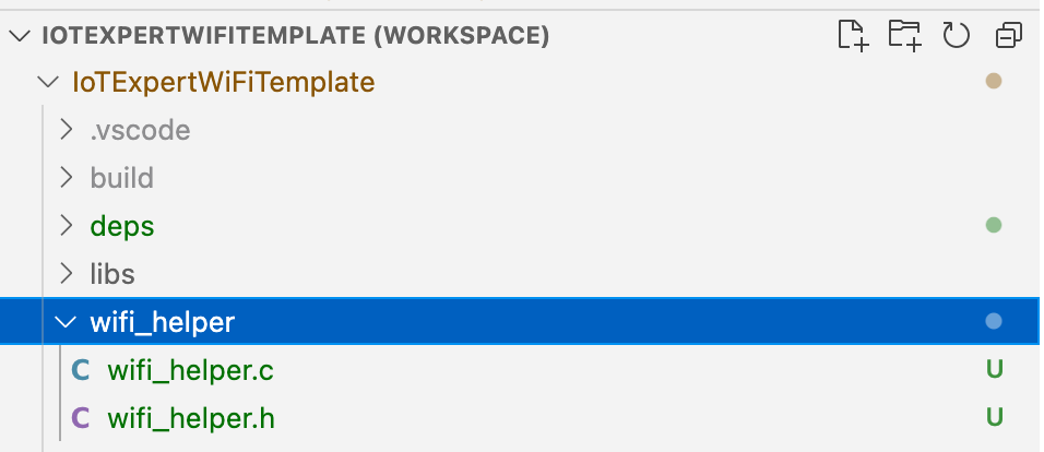
Follow these steps to make the c-library.  First, make a new directory in your project called “wifi_helper”.  You can do this in Visual Studio Code by pressing the folder button with the plus on it.

Then create the files wifi_helper.h and wifi_helper.c

In “wifi_helper.h” type in the public interface.  Specifically, that we want a function that takes a mac address returns a char*.  And another function that takes an IP address and returns a char*

#pragma once

#include "cy_wcm.h"

char *wifi_mac_to_string(cy_wcm_mac_t mac);

char *wifi_ntoa(cy_wcm_ip_address_t *ip_addr);


All right Hassane… yes these functions need comments.  Notice that I allocated a static buffer inside of these two function.  That means that these functions are NOT NOT NOT thread safe.  However, personally I think that is fine as I think that it is unlikely that they would ever be called from multiple threads.

#include "wifi_helper.h"
#include "cy_wcm.h"
#include <stdio.h>
#include "cy_utils.h"
#include "cy_log.h"

char *wifi_mac_to_string(cy_wcm_mac_t mac)
{
    static char _mac_string[] = "xx:xx:xx:xx:xx:xx";
    sprintf(_mac_string,"%02X:%02X:%02X:%02X:%02X:%02X",mac[0],mac[1],mac[2],mac[3],mac[4],mac[5]);
    return _mac_string; 
}


char *wifi_ntoa(cy_wcm_ip_address_t *ip_addr)
{
    static char _netchar[32];
    switch(ip_addr->version)
    {
        case CY_WCM_IP_VER_V4:
            sprintf(_netchar,"%d.%d.%d.%d", (uint8_t)ip_addr->ip.v4,
                (uint8_t)(ip_addr->ip.v4 >> 8), (uint8_t)(ip_addr->ip.v4 >> 16),
                (uint8_t)(ip_addr->ip.v4 >> 24));        break;
        case CY_WCM_IP_VER_V6:
            sprintf(_netchar,"%X:%X:%X:%X", (uint8_t)ip_addr->ip.v6[0],
                (uint8_t)(ip_addr->ip.v6[1]), (uint8_t)(ip_addr->ip.v6[2]),
                (uint8_t)(ip_addr->ip.v6[3]));
        break;
    }
    CY_ASSERT(buff[0] != 0); // SOMETHING should have happened
    return _netchar;
}

Git Repository

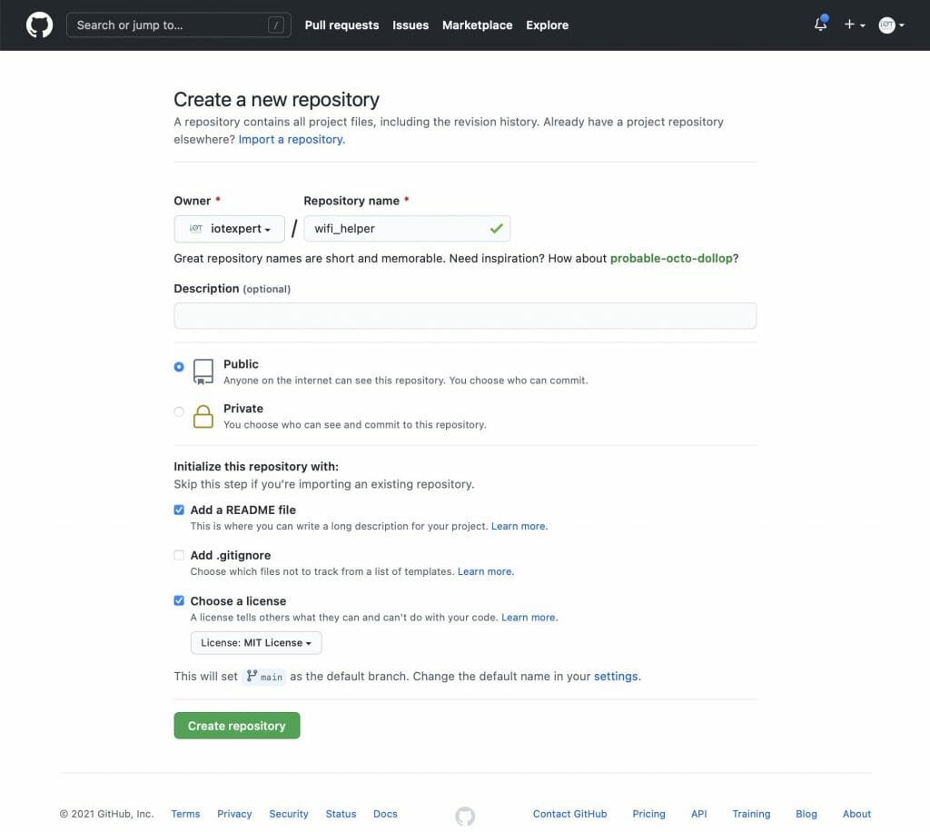
Now that I have the files I need in the library, I want to create a place on GitHub to hold the library.

Now we need to integrate the files into Git.  To do this you need to

  1. Initialize a new git repository (git init .)
  2. Add a remote (git remote add origin git@github.com:iotexpert/wifi_helper.git)
  3. Pull the remote files (README and LICENSE) with (git pull origin main)
  4. Add the wifi_helper files (git add wifi_helper.*)
  5. Commit the changes (git commit -m “added initial c files”)
  6. Push them to the remote (git push -u origin main)
arh (master *+) wifi_helper $ pwd
/Users/arh/proj/elkhorncreek3/IoTExpertWiFiTemplate/wifi_helper
arh (master *+) wifi_helper $ git init .
Initialized empty Git repository in /Users/arh/proj/elkhorncreek3/IoTExpertWiFiTemplate/wifi_helper/.git/
arh (main #) wifi_helper $ git remote add origin git@github.com:iotexpert/wifi_helper.git
arh (main #) wifi_helper $ git pull origin main
remote: Enumerating objects: 4, done.
remote: Counting objects: 100% (4/4), done.
remote: Compressing objects: 100% (4/4), done.
remote: Total 4 (delta 0), reused 0 (delta 0), pack-reused 0
Unpacking objects: 100% (4/4), 1.28 KiB | 436.00 KiB/s, done.
From iotexpert.github.com:iotexpert/wifi_helper
 * branch            main       -> FETCH_HEAD
 * [new branch]      main       -> origin/main
arh (main) wifi_helper $ git add wifi_helper.*
arh (main +) wifi_helper $ git commit -m "added initial c files"
[main f7d10b1] added initial c files
 2 files changed, 72 insertions(+)
 create mode 100644 wifi_helper.c
 create mode 100644 wifi_helper.h
arh (main) wifi_helper $ git push -u origin main
Enumerating objects: 5, done.
Counting objects: 100% (5/5), done.
Delta compression using up to 12 threads
Compressing objects: 100% (4/4), done.
Writing objects: 100% (4/4), 1.10 KiB | 1.10 MiB/s, done.
Total 4 (delta 0), reused 0 (delta 0), pack-reused 0
To iotexpert.github.com:iotexpert/wifi_helper.git
   3a1ad32..f7d10b1  main -> main
Branch 'main' set up to track remote branch 'main' from 'origin'.
arh (main) wifi_helper $ 

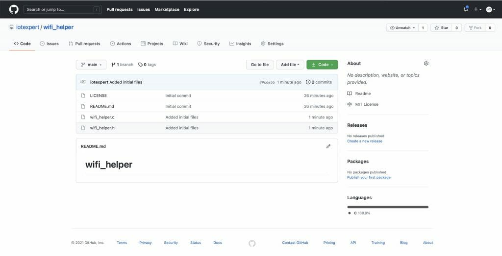
Now you will have something like this on GitHub.

Manifest Files

I would like to be able to have my new library show up in the library browser.  But how?  When the library browser starts up it needs to discover:

  1. Board Support Packages
  2. Template Projects
  3. Middleware Code Libraries

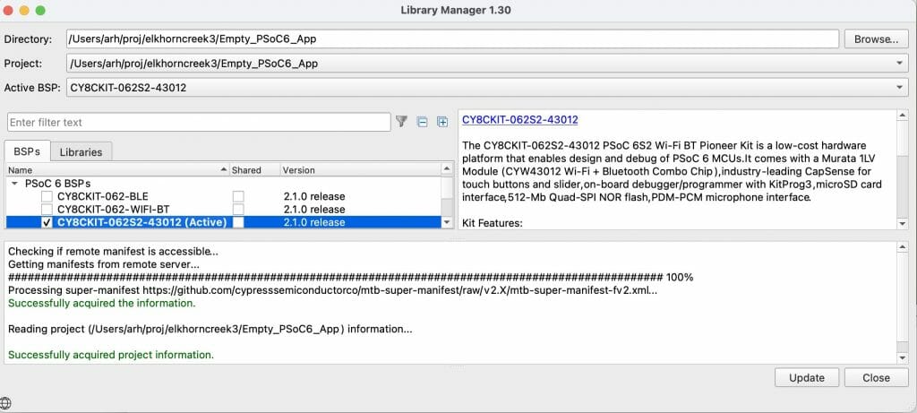
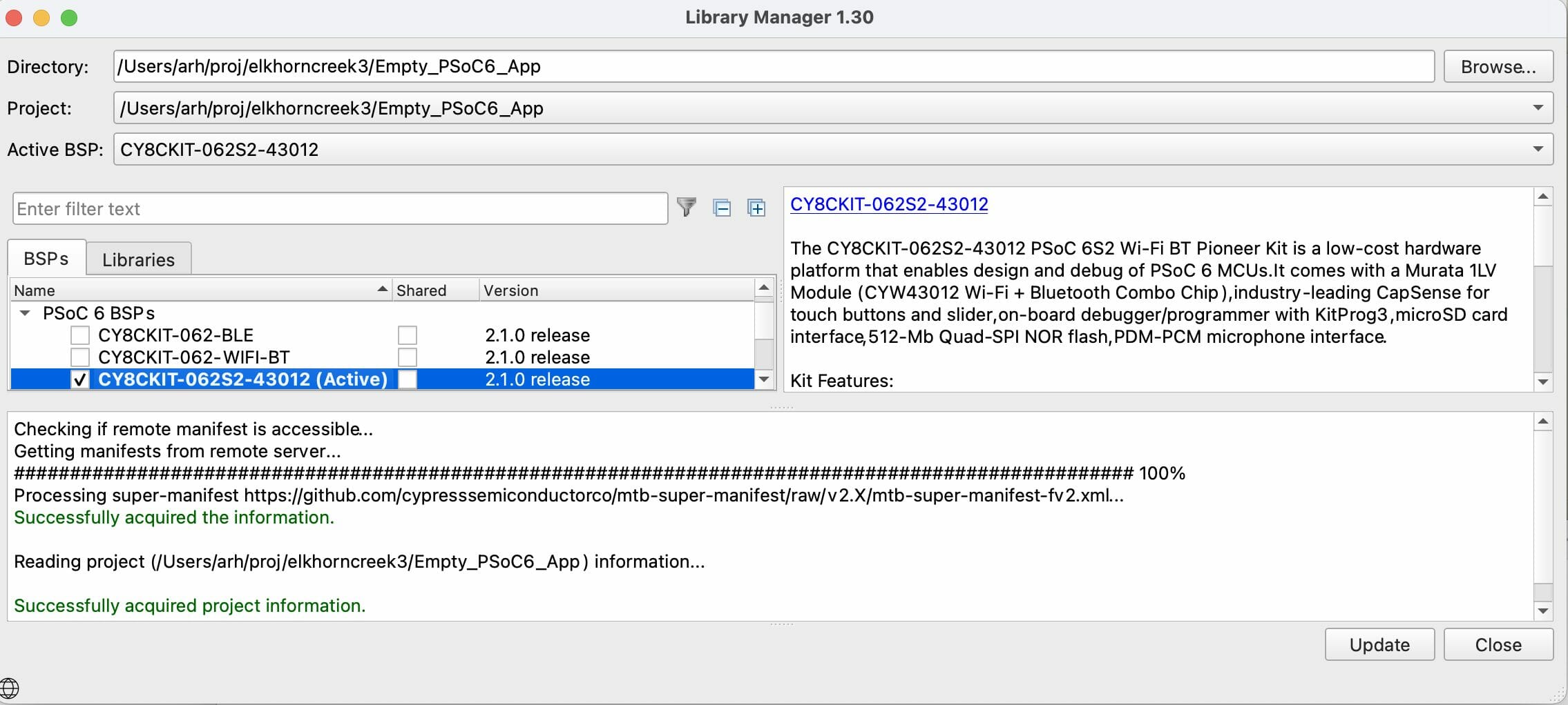
To do this, it reads a series of XML files called “manifests”.  These manifest files tell the library browser where to find the libraries.  If you have ever noticed the library browser (or the new project creator) it looks like this:

The message “Processing super-manifest …” give you a hint to go to https://raw.githubusercontent.com/cypresssemiconductorco/mtb-super-manifest/v2.X/mtb-super-manifest-fv2.xml

Here it is.  Notice that the XML scheme says that this file is a “super-manifest”.  Then notice that there are sections:

  • <board-manifest-list> these are BSPs
  • <app-manifest-list> these are template projects
  • <middleware-manifest-list> these are middleware code libraries
<super-manifest>
<board-manifest-list>
<board-manifest>
<uri>https://github.com/cypresssemiconductorco/mtb-bsp-manifest/raw/v2.X/mtb-bsp-manifest.xml</uri>
</board-manifest>
<board-manifest dependency-url="https://github.com/cypresssemiconductorco/mtb-bsp-manifest/raw/v2.X/mtb-bsp-dependencies-manifest.xml">
<uri>https://github.com/cypresssemiconductorco/mtb-bsp-manifest/raw/v2.X/mtb-bsp-manifest-fv2.xml</uri>
</board-manifest>
<board-manifest>
<uri>https://github.com/cypresssemiconductorco/mtb-bt-bsp-manifest/raw/v2.X/mtb-bt-bsp-manifest.xml</uri>
</board-manifest>
<board-manifest dependency-url="https://github.com/cypresssemiconductorco/mtb-bt-bsp-manifest/raw/v2.X/mtb-bt-bsp-dependencies-manifest.xml">
<uri>https://github.com/cypresssemiconductorco/mtb-bt-bsp-manifest/raw/v2.X/mtb-bt-bsp-manifest-fv2.xml</uri>
</board-manifest>
</board-manifest-list>
<app-manifest-list>
<app-manifest>
<uri>https://github.com/cypresssemiconductorco/mtb-ce-manifest/raw/v2.X/mtb-ce-manifest.xml</uri>
</app-manifest>
<app-manifest>
<uri>https://github.com/cypresssemiconductorco/mtb-ce-manifest/raw/v2.X/mtb-ce-manifest-fv2.xml</uri>
</app-manifest>
<app-manifest>
<uri>https://github.com/cypresssemiconductorco/mtb-bt-app-manifest/raw/v2.X/mtb-bt-app-manifest.xml</uri>
</app-manifest>
<app-manifest>
<uri>https://github.com/cypresssemiconductorco/mtb-bt-app-manifest/raw/v2.X/mtb-bt-app-manifest-fv2.xml</uri>
</app-manifest>
</app-manifest-list>
<middleware-manifest-list>
<middleware-manifest>
<uri>https://github.com/cypresssemiconductorco/mtb-mw-manifest/raw/v2.X/mtb-mw-manifest.xml</uri>
</middleware-manifest>
<middleware-manifest dependency-url="https://github.com/cypresssemiconductorco/mtb-mw-manifest/raw/v2.X/mtb-mw-dependencies-manifest.xml">
<uri>https://github.com/cypresssemiconductorco/mtb-mw-manifest/raw/v2.X/mtb-mw-manifest-fv2.xml</uri>
</middleware-manifest>
<middleware-manifest>
<uri>https://github.com/cypresssemiconductorco/mtb-bt-mw-manifest/raw/v2.X/mtb-bt-mw-manifest.xml</uri>
</middleware-manifest>
<middleware-manifest dependency-url="https://github.com/cypresssemiconductorco/mtb-bt-mw-manifest/raw/v2.X/mtb-bt-mw-dependencies-manifest.xml">
<uri>https://github.com/cypresssemiconductorco/mtb-bt-mw-manifest/raw/v2.X/mtb-bt-mw-manifest-fv2.xml</uri>
</middleware-manifest>
<middleware-manifest>
<uri>https://github.com/cypresssemiconductorco/mtb-wifi-mw-manifest/raw/v2.X/mtb-wifi-mw-manifest.xml</uri>
</middleware-manifest>
<middleware-manifest dependency-url="https://github.com/cypresssemiconductorco/mtb-wifi-mw-manifest/raw/v2.X/mtb-wifi-mw-dependencies-manifest.xml">
<uri>https://github.com/cypresssemiconductorco/mtb-wifi-mw-manifest/raw/v2.X/mtb-wifi-mw-manifest-fv2.xml</uri>
</middleware-manifest>
</middleware-manifest-list>
</super-manifest>

But you can’t modify this to add your own?  So what do you do now?  Cypress put in the capability for you to extend the system by creating a file called “~/.modustoolbox/manifest.loc”.  This file contains one or more URLs to super-manifest files (like the one above) where you can add whatever you want.

Here is the iotexpert manifest.loc

arh ~ $ cd ~/.modustoolbox/
arh .modustoolbox $ more manifest.loc
https://github.com/iotexpert/mtb2-iotexpert-manifests/raw/master/iotexpert-super-manifest.xml
arh .modustoolbox $

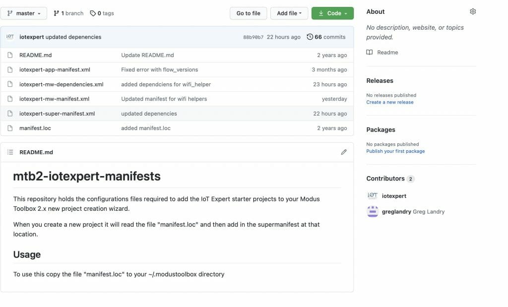
This file points to a super manifest file in a GitHub repository.  Here is the repository:

Notice that it has

  • iotexpert-super-manifest.xml – the top level iotexpert manifest
  • iotexpert-app-manifest.xml – my template projects
  • iotexpert-mw-manifest.xml – my middleware
  • manifest.loc – the file you need to put in your home directory
  • iotexpert-mw-dependencies.xml – a new file which I will talk about later

And the super manifest file that looks like this:

<super-manifest>
<board-manifest-list>
</board-manifest-list>
<app-manifest-list>
<app-manifest>
<uri>https://github.com/iotexpert/mtb2-iotexpert-manifests/raw/master/iotexpert-app-manifest.xml</uri>
</app-manifest>
</app-manifest-list>
<board-manifest-list>
</board-manifest-list>
<middleware-manifest-list>
<middleware-manifest dependency-url="https://github.com/iotexpert/mtb2-iotexpert-manifests/raw/master/iotexpert-mw-dependencies.xml">
<uri>https://github.com/iotexpert/mtb2-iotexpert-manifests/raw/master/iotexpert-mw-manifest.xml</uri>
</middleware-manifest>
</middleware-manifest-list>
</super-manifest>

To add the library we created above, I need to add the new middleware into my middleware manifest.  Modify the file “iotexpert-mw-manifest.xml” to have the new middleware.

<middleware>
<name>WiFi Helper Utilties</name>
<id>wifi_helper</id>
<uri>https://github.com/iotexpert/wifi_helper</uri>
<desc>A library WiFi Helper utilities (e.g. aton)</desc>
<category>IoT Expert</category>
<req_capabilities>psoc6</req_capabilities>
<versions>
<version flow_version="2.0">
<num>main</num>
<commit>main</commit>
<desc>main</desc>
</version>
</versions>
</middleware>

If you recall I have the “wifi_helper” directory inside of my project.  Not what I want (because I want it to be pulled using the library browser).  So I move out my project directory.  Now, let’s test the whole thing by running the library browser.

arh (master *+) IoTExpertWiFiTemplate $ pwd
/Users/arh/proj/elkhorncreek3/IoTExpertWiFiTemplate
arh (master *+) IoTExpertWiFiTemplate $ mv wifi_helper/ ~/proj/
arh (master *+) IoTExpertWiFiTemplate $ make modlibs
Tools Directory: /Applications/ModusToolbox/tools_2.3
CY8CKIT-062S2-43012.mk: ./libs/TARGET_CY8CKIT-062S2-43012/CY8CKIT-062S2-43012.mk
Launching library-manager

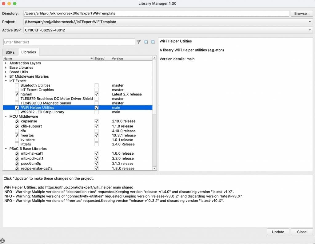
Excellent the WiFI Helper utilities show up.

And when I run the “update” the files show up in the project.

Add Dependencies

If you recall from the code I had this include:

#include "cy_wcm.h"

That means that I am dependent on the library “wifi-connection-manager”.  To make this work I create a new file called “iotexpert-mw-depenencies.xml”.  In that file I tell the system that “wifi_helper” is now dependent on “wcm”

<dependencies version="2.0">
<depender>
<id>wifi_helper</id>
<versions>
<version>
<commit>main</commit>
<dependees>
<dependee>
<id>wcm</id>
<commit>latest-v2.X</commit>
</dependee>
</dependees>
</version>
</versions>
</depender>
</dependencies>

Once I have that file, I add that depencency file to my middleware manifest file.

  <middleware-manifest-list>
<middleware-manifest dependency-url="https://github.com/iotexpert/mtb2-iotexpert-manifests/raw/master/iotexpert-mw-dependencies.xml">
<uri>https://github.com/iotexpert/mtb2-iotexpert-manifests/raw/master/iotexpert-mw-manifest.xml</uri>
</middleware-manifest>
</middleware-manifest-list>
</super-manifest>

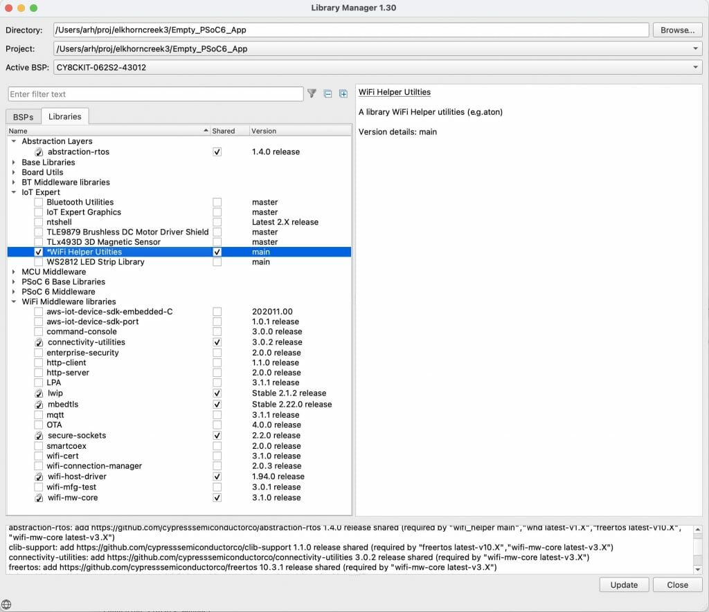
Now when I start the library browser and add the “WiFi Help Utilities” it will automatically add the wireless connection manager (and all of the libraries that the wcm is dependent on.

In the next article I will add Scanning functionality to the WiFi Task.
AnyCloud WiFi Template + WiFi Helper Library (Part 2): Enable the WiFi Network

Summary

Instructions on using the AnyCloud Wireless Connection manager to enable WiFi.  This article is Part 2 of a series that will build a new IoT Expert template project for WiFi.

Article
(Part 1) Create Basic Project & Add Cypress Logging Functionality
(Part 2) Create New Thread to manage WiFi using the Wireless Connection Manager
(Part 3) Create a New Middleware Library with WiFi helper functions
(Part 4) Add WiFi Scan
Add WiFi Connect
Add WiFi Disconnect
Add WiFi Ping
Add Gethostbyname
Add MDNS
Add Status
Add StartAP
Make a new template project (update manifest)

Story

In the last article I got things going by starting from the old template, fixing up the Visual Studio Code configuration, adding the new Cypress Logging functionality and then testing everything.

In this article I will

  1. Create new task to manage WiFi
  2. Add Wireless Connection Manager to the project
  3. Create wifi_task.h and wifi_task.c
  4. Update usrcmd.c to send commands to the WiFi task

Create New Task to Manage WiFi

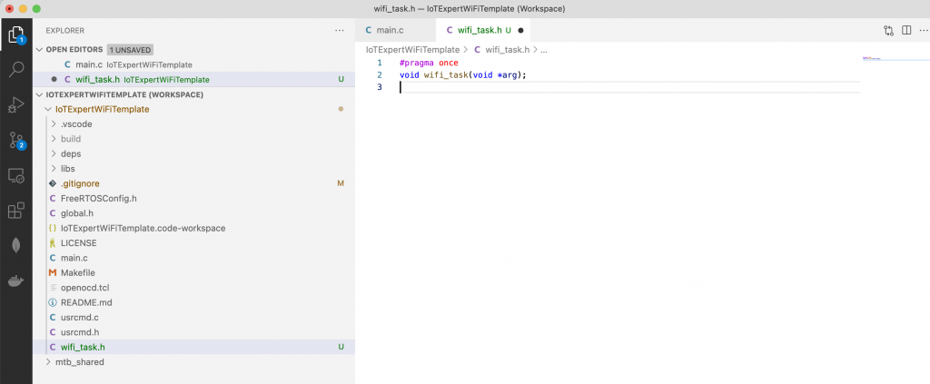
I am going to start by creating new a new task (called wifi_task) that will be responsible for managing the WiFi connection.  In Visual Studio Code you can create a new file by pressing the little document with the + on it.  You will need a file “wifi_task.h” and one “wifi_task.c”

Once you have wifi_task.h you will need to add the function prototype for the wifi_task.  In addition add a “guard”.  I like to use “#pragma once”
Here is copyable code.

#pragma once
void wifi_task(void *arg);

In wifi_task.c Ill start with a simple blinking LED function.  Well actually it will do a print instead of a blink.  Here it is:

#include "wifi_task.h"
#include "FreeRTOS.h"
#include "task.h"
#include <stdio.h>
void wifi_task(void *arg)
{
while(1)
{
vTaskDelay(1000);
printf("blink\n");
}
}

Now that I have a wifi_task (which doesn’t do much) lets update main.c.  First include the wifi_task.h

#include "wifi_task.h"

Then create the task.  Notice that I start with a pretty big stack.
xTaskCreate(wifi_task,   "WiFi"       , configMINIMAL_STACK_SIZE*20,0 /* args */ ,0 /* priority */, 0);

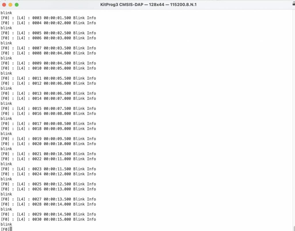
When you run this, you will have the “blink” interleaved with the blink from the last article.
Add Wireless Connection Manager

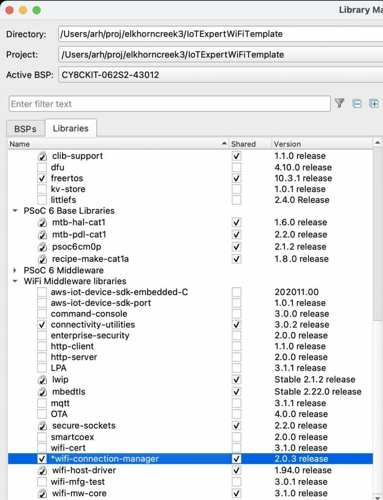
You next step is to add the wireless connection manager.  Start the library browser by running “make modlibs”.  Then click on the wifi-connection-manager”.  Notice that when you do that, it will bring in a bunch of other libraries as well.  These are all libraries that it (the WiFi-Connection-Manager) is depend on.

If you look in the wireless connection manager documentation you will find this nice note.  It says that the WCM uses the Cypress logging functionality and you can turn it on with a #define.  That’s cool.  So now I edit the Makefile and add the define.

The the documentation also says that this library depends on the “Wi-Fi Middleware Core”

If you go to the Wi-Fi Middleware core library documentation you will see instructions that say that you need to

  1. Enable & Configure LWIP
  2. Enable & Configure MBEDTLS
  3. Enable & Configure the Cypress RTOS Abstraction

In order to do that you will need to two things

  1. Copy the configuration files into your project
  2. Setup some options in the Makefile

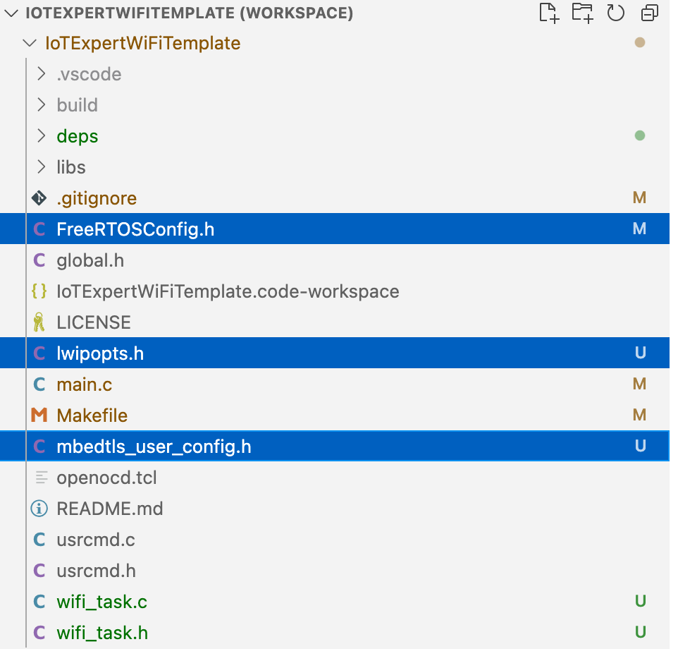
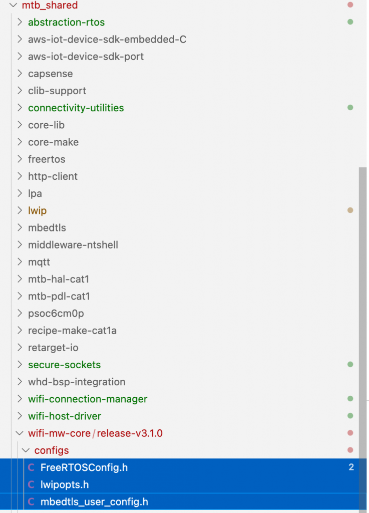
Start by copying the file.  They give you default configurations in mtb_share/wifi-mw-core/version/configs.  You will want to copy those files into your project.  This can be done in the Visual Studio Code interface using ctrl-c and ctrl-v

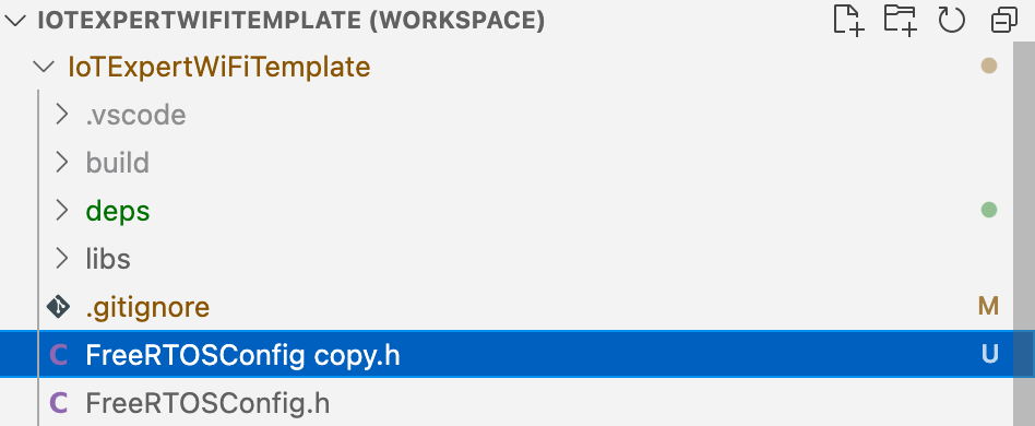
Notice that I now have two FreeRTOSConfig files.  So, delete the original file and rename the copied file.

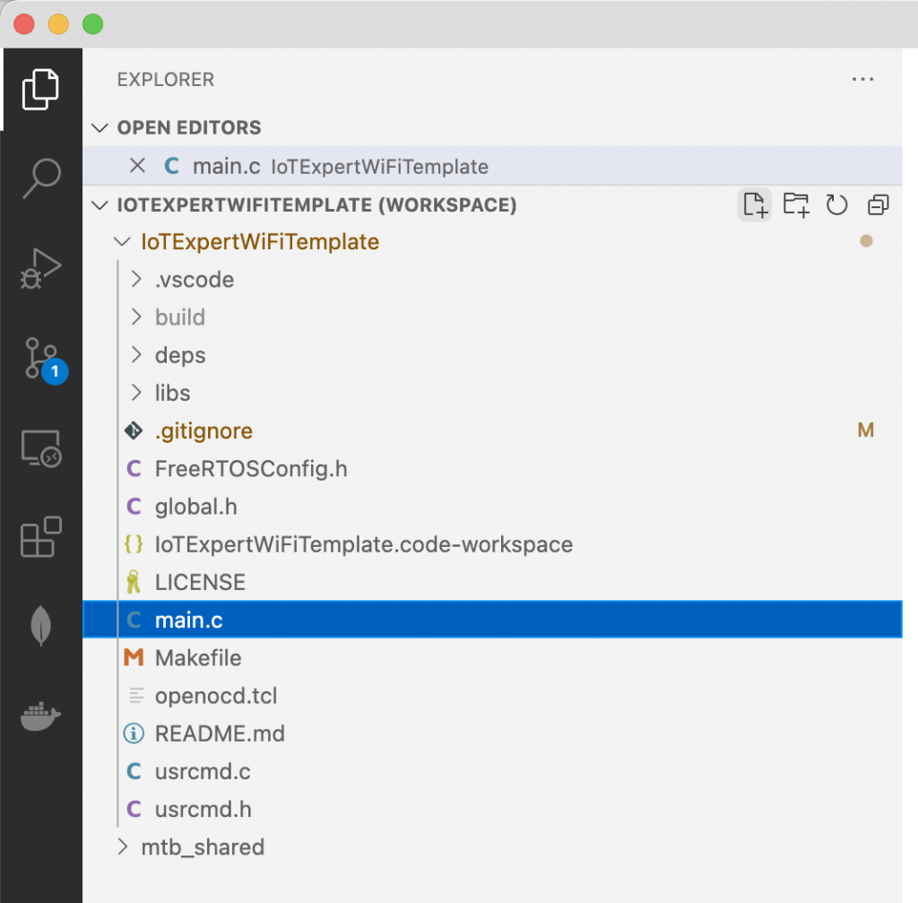
Now your project should look like this:

The next step is to fix the Makefile by adding some defines.


DEFINES=CY_RETARGET_IO_CONVERT_LF_TO_CRLF
DEFINES+=CYBSP_WIFI_CAPABLE CY_RTOS_AWARE
DEFINES+=MBEDTLS_USER_CONFIG_FILE='"mbedtls_user_config.h"'
DEFINES+=ENABLE_WIFI_MIDDLEWARE_LOGS

The add the required components

COMPONENTS=FREERTOS LWIP MBEDTLS PSOC6HAL

Update wifi_task.c

My wifi task is going to work by

  1. Sitting on Queue waiting for messages of “wifi_cmd_t”
  2. When those messages come in, execute the right command.

Start by adding some includes to the wifi_task.c

#include <stdio.h>
#include "wifi_task.h"
#include "FreeRTOS.h"
#include "task.h"
#include "queue.h"
#include "cy_wcm.h"

Then define the legal commands.  I will add a bunch of more commands in the future articles.  But for this article there will be only one command.  Enable.  The command message is

  1. The command
  2. Three args of unknown type

In addition you will require

  1. The command queue
  2. An initialize state variable
  3. A way to keep track of what mode you are in (AP, STA or APSTA)
typedef enum {
WIFI_CMD_ENABLE,
} wifi_cmd_t;
typedef struct {
wifi_cmd_t cmd;
void *arg0;
void *arg1;
void *arg2;
} wifi_cmdMsg_t;
static QueueHandle_t wifi_cmdQueue;
static bool wifi_initialized=false;
static cy_wcm_interface_t wifi_network_mode;

The first “command” that I will create is the enable.  This will

  1. Setup the interface
  2. Initialize the WiFi.  The simple init command actually does a bunch of stuff, including powering on the wifi chip, downloading the firmware into it, setting up all of the tasks in the RTOS, enabling the LWIP and MBEDTLS
static void wifi_enable(cy_wcm_interface_t interface)
{
cy_rslt_t result;
cy_wcm_config_t config = {.interface = interface}; 
result = cy_wcm_init(&config); // Initialize the connection manager
CY_ASSERT(result == CY_RSLT_SUCCESS);
result = cy_wcm_register_event_callback(wifi_network_event_cb);
CY_ASSERT(result == CY_RSLT_SUCCESS);
wifi_network_mode = interface;
wifi_initialized = true;
printf("\nWi-Fi Connection Manager initialized\n");
}

In the previous block of code notice that I register a callback.  The callback looks like a switch that prints out messages based on the event type.  Notice that there are three lines which are commented out – which we will fix in the next article.

static void wifi_network_event_cb(cy_wcm_event_t event, cy_wcm_event_data_t *event_data)
{
cy_wcm_ip_address_t ip_addr;
switch(event)
{
case CY_WCM_EVENT_CONNECTING:            /**< STA connecting to an AP.         */
printf("Connecting to AP ... \n");
break;
case CY_WCM_EVENT_CONNECTED:             /**< STA connected to the AP.         */
printf("Connected to AP and network is up !! \n");
break;
case CY_WCM_EVENT_CONNECT_FAILED:        /**< STA connection to the AP failed. */
printf("Connection to AP Failed ! \n");
break;
case CY_WCM_EVENT_RECONNECTED:          /**< STA reconnected to the AP.       */
printf("Network is up again! \n");
break;
case CY_WCM_EVENT_DISCONNECTED:         /**< STA disconnected from the AP.    */
printf("Network is down! \n");
break;
case CY_WCM_EVENT_IP_CHANGED:           /**< IP address change event. This event is notified after connection, re-connection, and IP address change due to DHCP renewal. */
cy_wcm_get_ip_addr(wifi_network_mode, &ip_addr, 1);
//             printf("Station IP Address Changed: %s\n",wifi_ntoa(&ip_addr));
break;
case CY_WCM_EVENT_STA_JOINED_SOFTAP:    /**< An STA device connected to SoftAP. */
//           printf("STA Joined: %s\n",wifi_mac_to_string(event_data->sta_mac));
break;
case CY_WCM_EVENT_STA_LEFT_SOFTAP:      /**< An STA device disconnected from SoftAP. */
//            printf("STA Left: %s\n",wifi_mac_to_string(event_data->sta_mac));
break;
}
}

Now I want to update the main loop of the WiFI task.  It is just an infinite loop that processes command messages (from other tasks).
void wifi_task(void *arg)
{
wifi_cmdQueue = xQueueCreate(10,sizeof(wifi_cmdMsg_t));
wifi_cmdMsg_t msg;
while(1)
{
xQueueReceive(wifi_cmdQueue,&msg,portMAX_DELAY);
switch(msg.cmd)
{
case WIFI_CMD_ENABLE:
printf("Received wifi enable message\n");
wifi_enable((cy_wcm_interface_t)msg.arg0);
break;
}
}
}

In the other tasks in the system you “COULD” create a message and submit it to the queue.  I always think that it is easier if you create a function which can be called in the other threads.  Here is the wifi_enable function.  This function takes a char * of either “STA”, “AP”, or “APSTA” and then submits the right message to the queue.

bool wifi_cmd_enable(char *interface)
{
wifi_cmdMsg_t msg;
msg.cmd = WIFI_CMD_ENABLE;
msg.arg0 = (void *)CY_WCM_INTERFACE_TYPE_STA;
if(strcmp(interface,"STA") == 0)
msg.arg0 = (void *)CY_WCM_INTERFACE_TYPE_STA;
else if(strcmp(interface,"AP") == 0)
msg.arg0 = (void *)CY_WCM_INTERFACE_TYPE_AP;
else if(strcmp(interface,"APSTA") == 0)
msg.arg0 = (void *)CY_WCM_INTERFACE_TYPE_AP_STA;
else
{
printf("Legal options are STA, AP, APSTA\n");
return false;
}
xQueueSend(wifi_cmdQueue,&msg,0);
return true;
}

Once I have the nice function for the other tasks, I add it to the public interface in wifi_task.h

#pragma once
#include <stdbool.h>
void wifi_task(void *arg);
bool wifi_cmd_enable(char *interface);

Add a new user command “net”

Now that I have the wifi_task setup I want to add a “net” command to the command line shell.  Start by adding the include.

#include "wifi_task.h"

Then create a function prototype for a new command.

static int usrcmd_net(int argc, char **argv);

Add the command to the list of commands that the shell knows.

static const cmd_table_t cmdlist[] = {
{ "help", "This is a description text string for help command.", usrcmd_help },
{ "info", "This is a description text string for info command.", usrcmd_info },
{ "clear", "Clear the screen", usrcmd_clear },
{ "pargs","print the list of arguments", usrcmd_pargs},
#ifdef configUSE_TRACE_FACILITY 
#if configUSE_STATS_FORMATTING_FUNCTIONS ==1
{ "tasks","print the list of RTOS Tasks", usrcmd_list},
#endif
#endif
{ "net","net [help,enable]",usrcmd_net},
};

Then create the net command.  I want a BUNCH of net commands.  They will include help, enable, connect, disconnect, …. but for now we will start with enable.  This function just calls the wifi_enable command that we added to the wifi_task.h interface.

static int usrcmd_net(int argc, char **argv)
{
if(argc == 1 || strcmp("help",argv[1]) == 0)
{
printf("net [help,enable,connect,disconnect,mdns,scan,ping,lookup]\n");
printf("%-35s %s\n","net enable","Enable the WiFi Driver & load the WiFi Firmware");
return 0;
}
if(strcmp("enable",argv[1])==0)
{
if(argc == 2)
wifi_cmd_enable("STA");
else
wifi_cmd_enable(argv[2]);        
return 0;
}
return 0;
}

Test

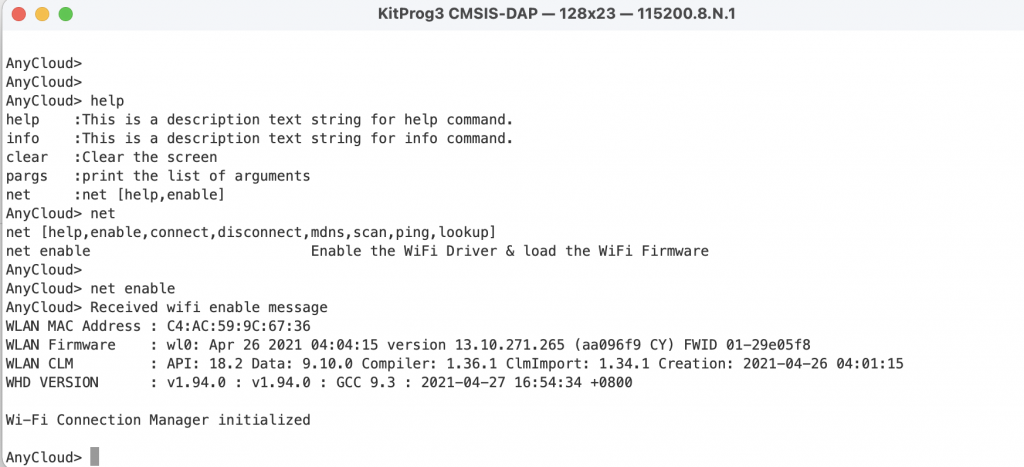
Program and test.  Now the “net enable” works.  Notice that it gives you the output about the wifi firmware being loaded into the chip.  Then it tells you that the chip is enabled and the connection manager is rolling.

In the next article I will create a new library of helper functions for wifi.

AnyCloud WiFi Template + WiFi Helper Library (Part 1): Introduction

Summary

The first article in a series that discusses building a new IoT project using Modus Toolbox and the AnyCloud SDK.  Specifically:

  1. The new-ish Error Logging library
  2. AnyCloud Wireless Connection Manager
  3. Creation of New Libraries and Template Projects
  4. Dual Role WiFi Access Point and Station using CYW43012
  5. MDNS

Story

I am working on a new implementation of my Elkhorn Creek IoT monitoring system.  In some of the previous articles I discussed the usage of the Influx Database and Docker as a new cloud backend.  To make this whole thing better I wanted to replace the Raspberry Pi (current system) with a PSoC 6 MCU and a CYW43012 WiFi Chip.  In order to do this, I need to make the PSoC 6 talk to the Influx Database using the WiFi and the Influx DB WebAPI.  I started to build this from my IoT Expert template, but quickly realized that I should make a template project with WiFi.

In this series of article I teach you how to use the Wireless Connection Manager, make new libraries and make new template projects.  Here is the agenda:

Article
(Part 1) Create Basic Project & Add Cypress Logging Functionality
(Part 2) Create New Thread to manage WiFi using the Wireless Connection Manager
(Part 3) Create a New Middleware Library with WiFi helper functions
(Part 4) Add WiFi Scan
Add WiFi Connect
Add WiFi Disconnect
Add WiFi Ping
Add Gethostbyname
Add MDNS
Add Status
Add StartAP
Make a new template project (update manifest)

Create Basic Project

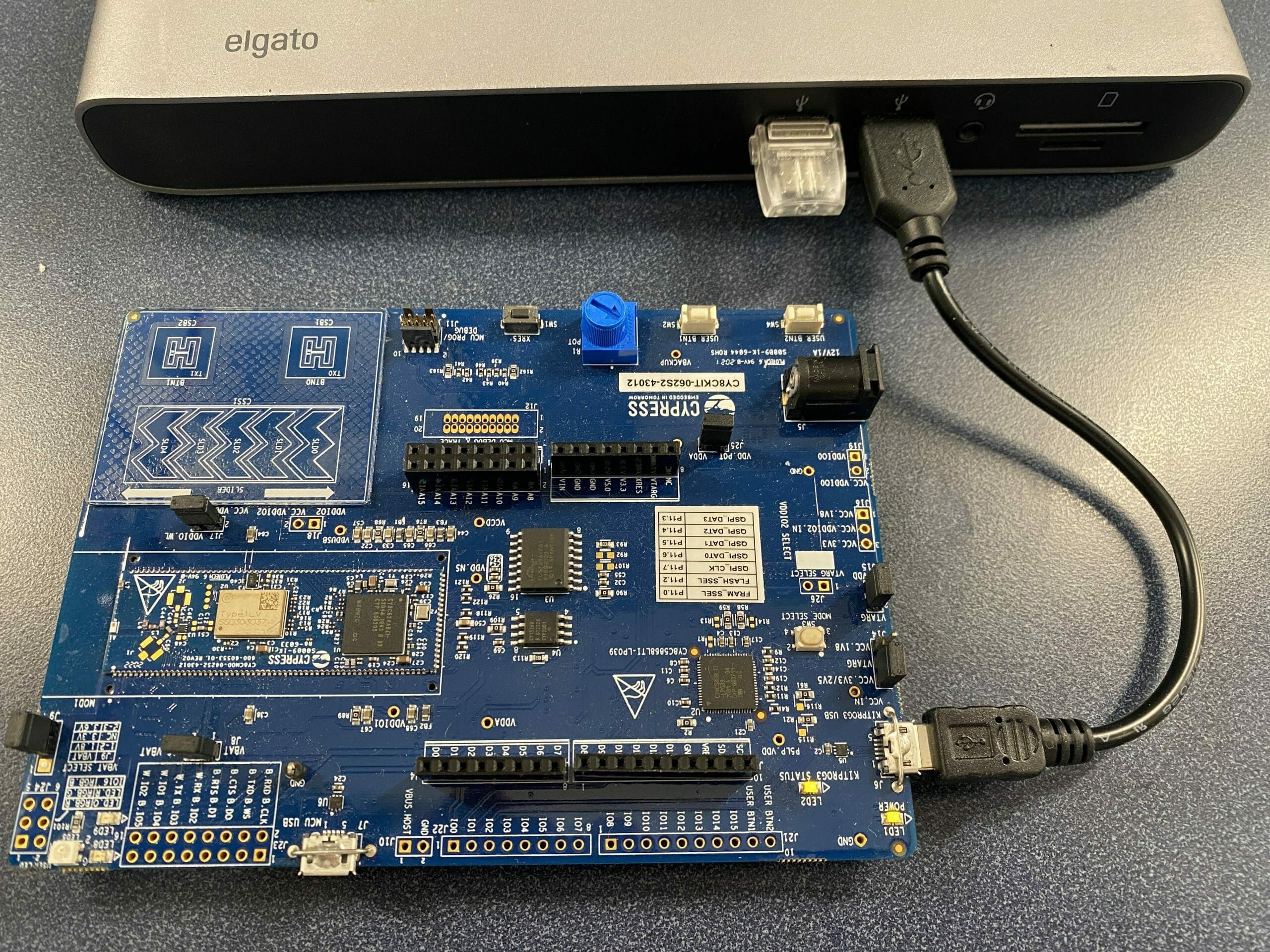
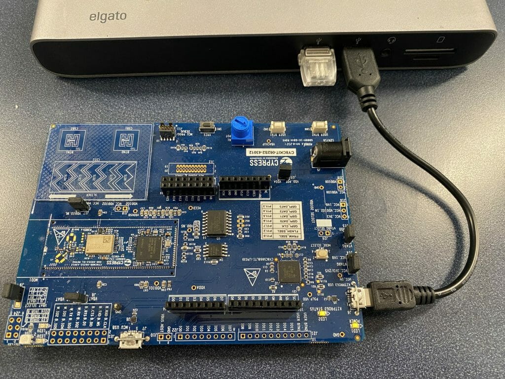
Today I happen to have a CY8CKIT-062S2-43012 on my desk.
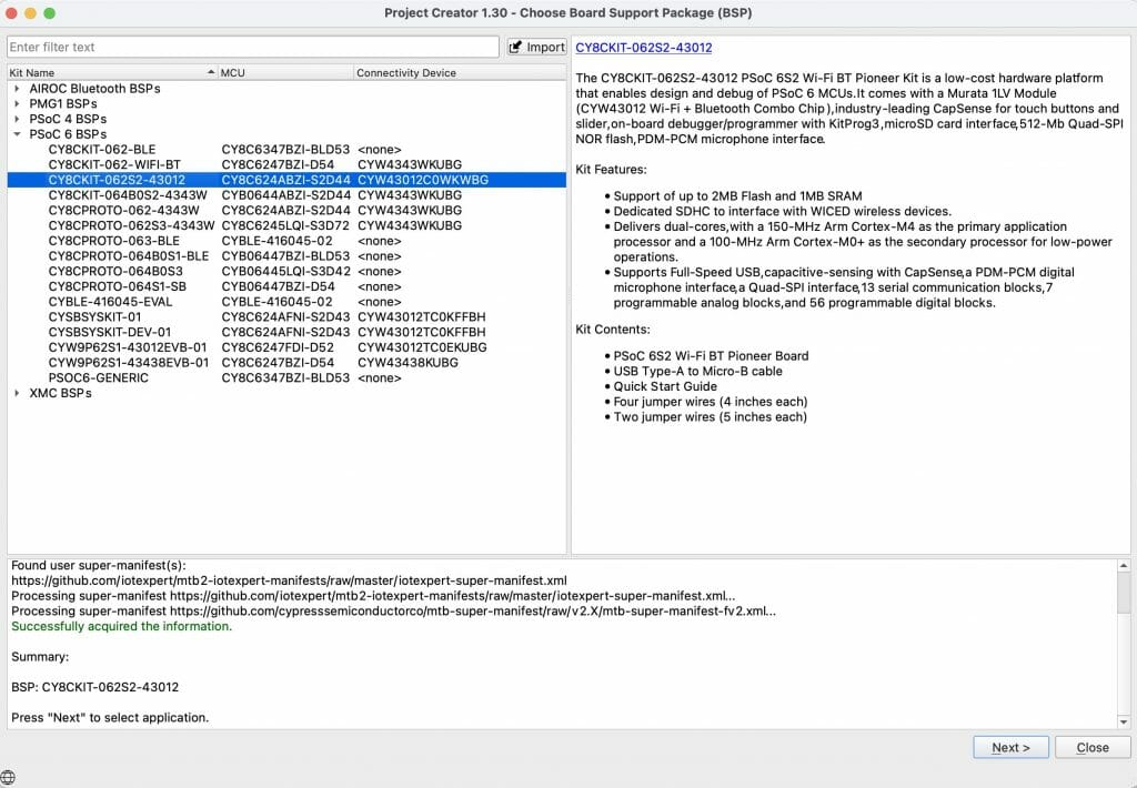
So that looks like a good place to start.  Pick that development kit in from the new project creator.

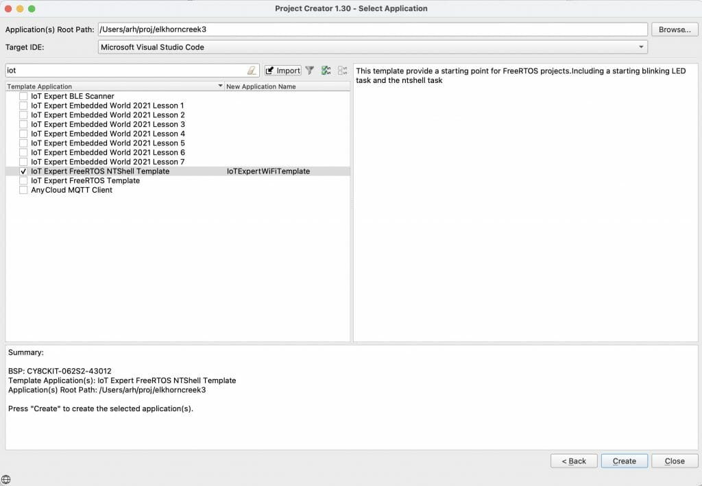
I want to start from my tried and true NT Shell, FreeRTOS Template.  If you use the filter window and type “iot” it will filter things down to just the IoT templates.  Notice that I selected that I want to get a “Microsoft Visual Studio Code” target workspace.

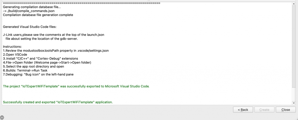
After clicking create you will get a new project.

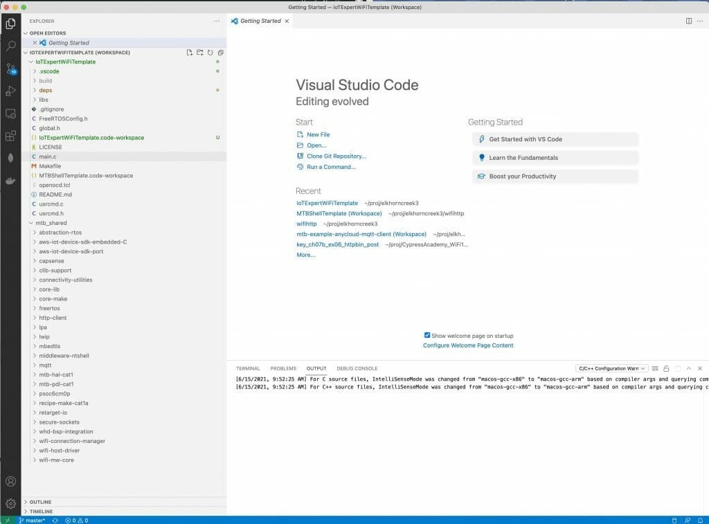
Something weird happened.  Well actually something bad happened.  When I start Visual Studio Code I get the message that I have multiple workspace files.  Why is that?

So I pick the first one.

Now there is a problem.  In the Makefile for this project I find out that the “APPNAME” is MTBShellTemplate

# Name of application (used to derive name of final linked file).
APPNAME=MTBShellTemplate

By default when you run “make vscode” it will make a workspace file for you with the name “APPNAME.code-workspace”.  This has now created a problem for you.  Specifically, if you regenerate the workspace by running “make vscode” you will update the WRONG file.  When the new project creator runs the “make vscode” it uses the name you entered on that form, not the one in the Makefile.

To fix this, edit he Makefile & delete the old MTB…workspace.  Then re-run make vscode

APPNAME=IoTExpertWiFiTemplate

I have been checking in the *.code-workspace file, but that may not be exactly the right thing to do.  I am not sure.  Oh well.  Here is what you screen should look like now that you have Visual Studio Code going.

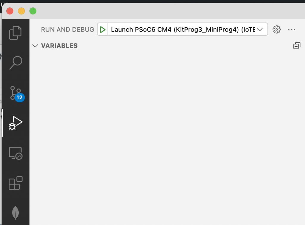
I always like to test things to make sure everything works before I start editing.  So, press the play button, then the green play button.

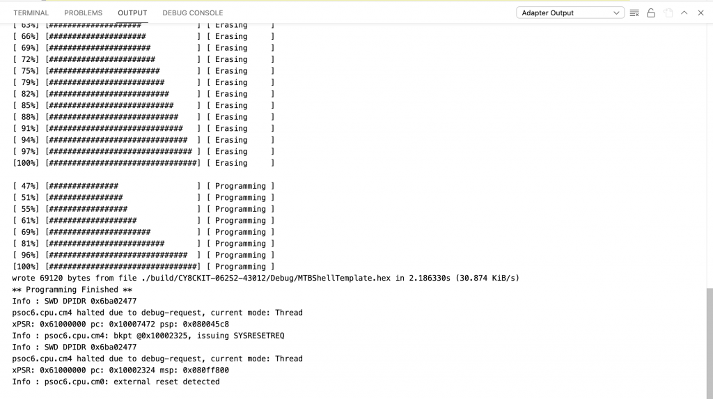
It should build and program the development kit.

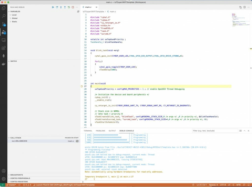
Then stop at main.

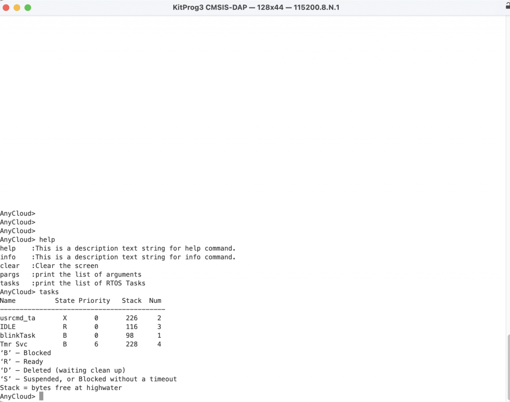
Press play and your terminal should look something like this.  Notice that I typed “help” and “tasks”

Add the Cypress Logging Functionality

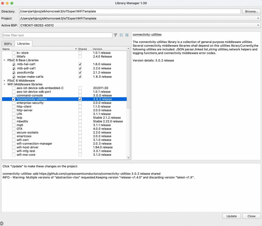
Sometime recently the Software team added a logging capability.  This seems like a good time to try that that.  Start the library browser by running “make modlibs”.  Then enable the “connectivity-utilities”.  For some silly reason that is where the logging functions were added.

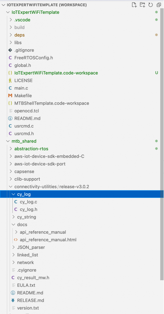
If you look in the “mtb_shared” you will now the cy_log directory.

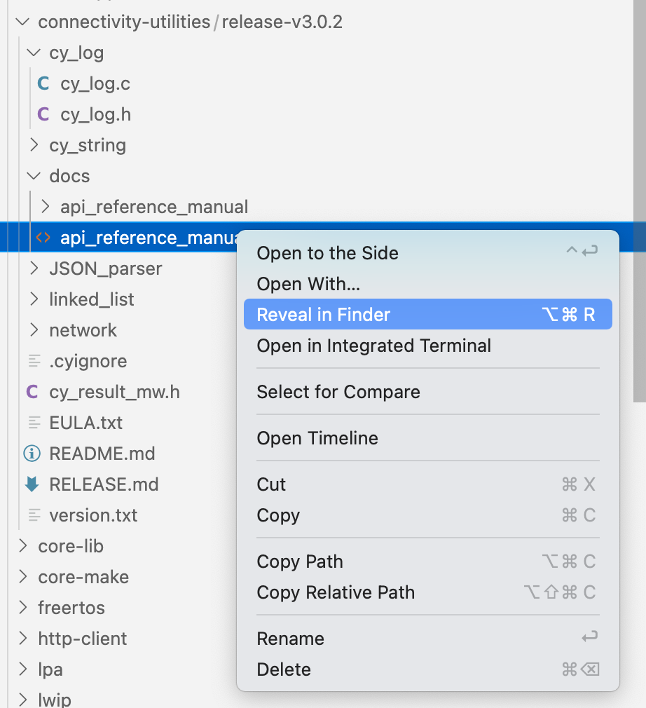
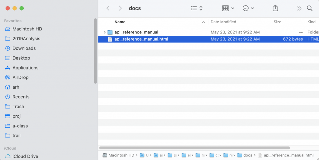
Then click on the “api_reference.html”

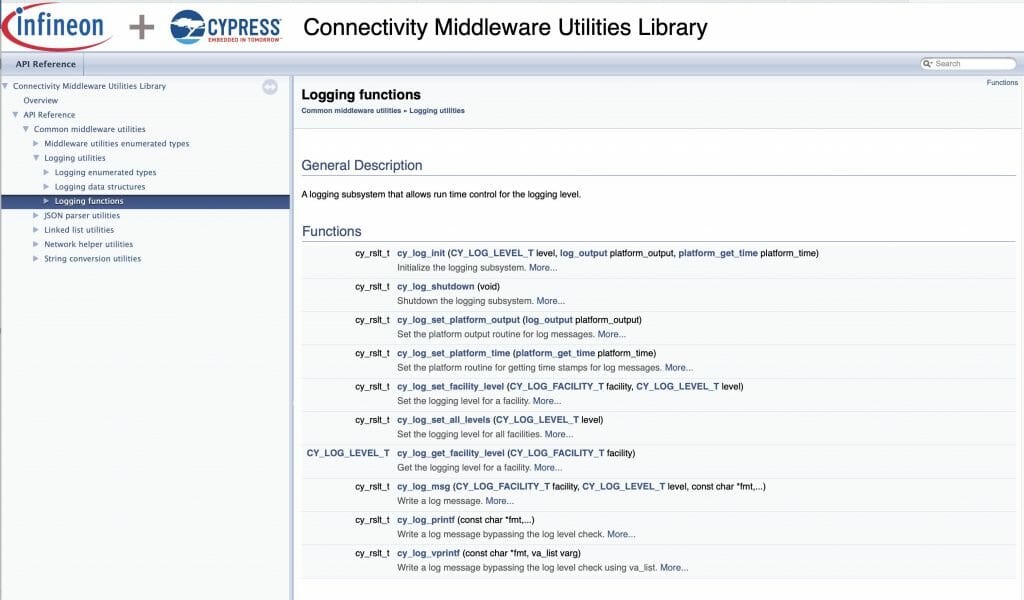
And open it.

Cool.  This gives you some insight into the capability.

A simple test will be to printout a “blink” message in sync with the default blinking led.  To do this, I modify the blink_task in main.c  Take the following actions

  1. Add the include “cy_log.h”
  2. Add the initialization call “cy_log_init”
  3. Printout a test message using “cy_log_msg”
  4. Fix the stack
#include "cyhal.h"
#include "cybsp.h"
#include "cy_retarget_io.h"
#include <stdio.h>
#include "FreeRTOS.h"
#include "task.h"
#include "usrcmd.h"
#include "cy_log.h"
volatile int uxTopUsedPriority ;
TaskHandle_t blinkTaskHandle;
void blink_task(void *arg)
{
cyhal_gpio_init(CYBSP_USER_LED,CYHAL_GPIO_DIR_OUTPUT,CYHAL_GPIO_DRIVE_STRONG,0);
for(;;)
{
cy_log_msg(CYLF_DEF,CY_LOG_INFO,"Blink Info\n");
cyhal_gpio_toggle(CYBSP_USER_LED);
vTaskDelay(500);
}
}
int main(void)
{
uxTopUsedPriority = configMAX_PRIORITIES - 1 ; // enable OpenOCD Thread Debugging
/* Initialize the device and board peripherals */
cybsp_init() ;
__enable_irq();
cy_retarget_io_init(CYBSP_DEBUG_UART_TX, CYBSP_DEBUG_UART_RX, CY_RETARGET_IO_BAUDRATE);
cy_log_init(CY_LOG_INFO,0,0);
// Stack size in WORDs
// Idle task = priority 0
xTaskCreate(blink_task, "blinkTask", configMINIMAL_STACK_SIZE*2,0 /* args */ ,0 /* priority */, &blinkTaskHandle);
xTaskCreate(usrcmd_task, "usrcmd_task", configMINIMAL_STACK_SIZE*4,0 /* args */ ,0 /* priority */, 0);
vTaskStartScheduler();
}

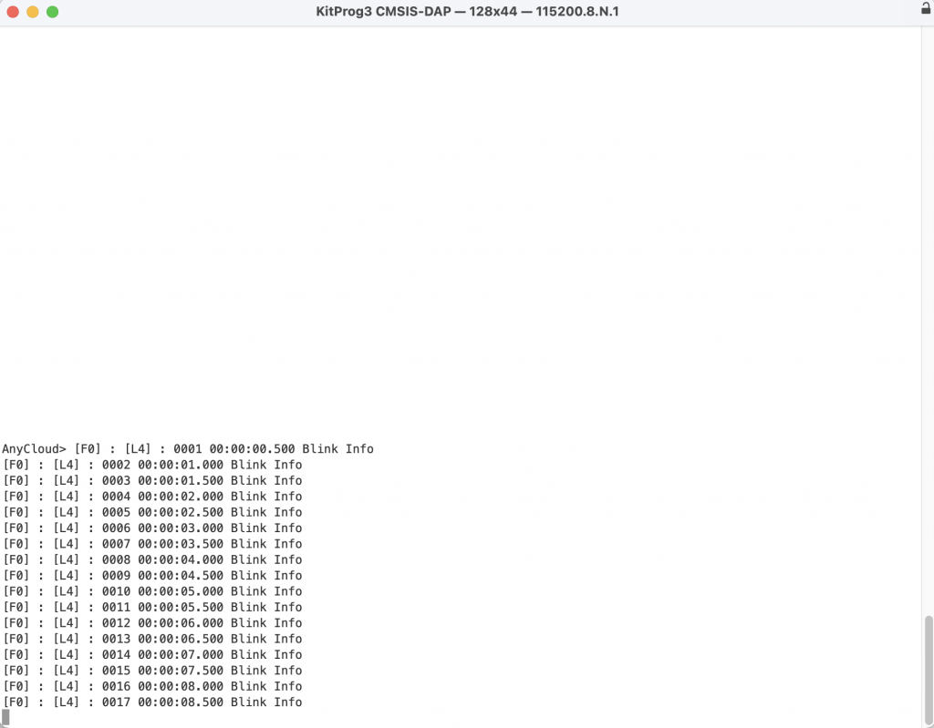
When you run this, you will get the message repeatedly coming on the screen (probably gonna-want-a delete this before you go on)

Now that we have a working project with logging, in the next article Ill add WiFi

Mouser PSoC 6-WiFi-BT L8: Integrate WiFi and AWS Into the Game

Designing low-power, cloud-connected IoT devices with PSoC® 6 MCU’s and WICED® Wi-Fi/Bluetooth

Summary

In this lesson we will move the subscriber app functionality into the main GameBle project (now called GameBleAws).  In order to do this, you need to turn the subscriber into a thread, and fix it so that messages that are sent to the PADDLE topic get turned into messages that can be sent to the paddleQueue.

To implement this lesson I will follow these steps:

  1. Create a New Project starting from L6GameBle
  2. Copy over subscriber.c and wifi_config_dct.h
  3. Update the Makefile
  4. Create subscriber.h
  5. Update main.c
  6. Update subscriber.c
  7. Test

Create a New Project

Copy and paste the L6GameBle project into a new project called L8GameBleAws using Copy/Paste

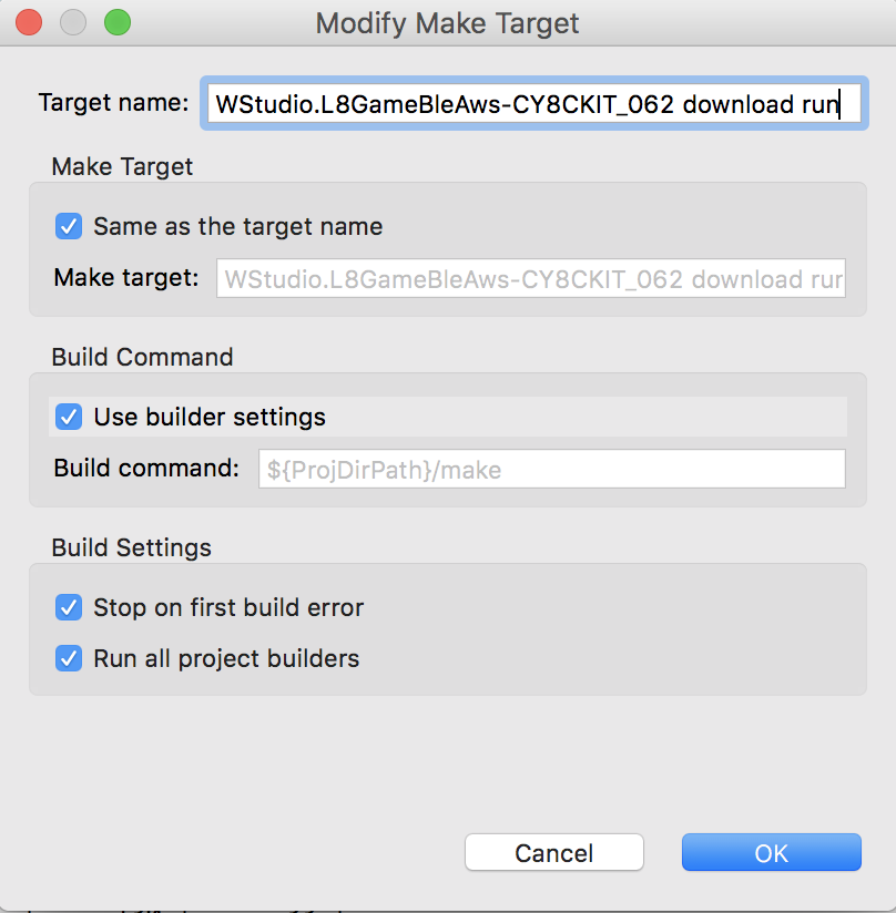
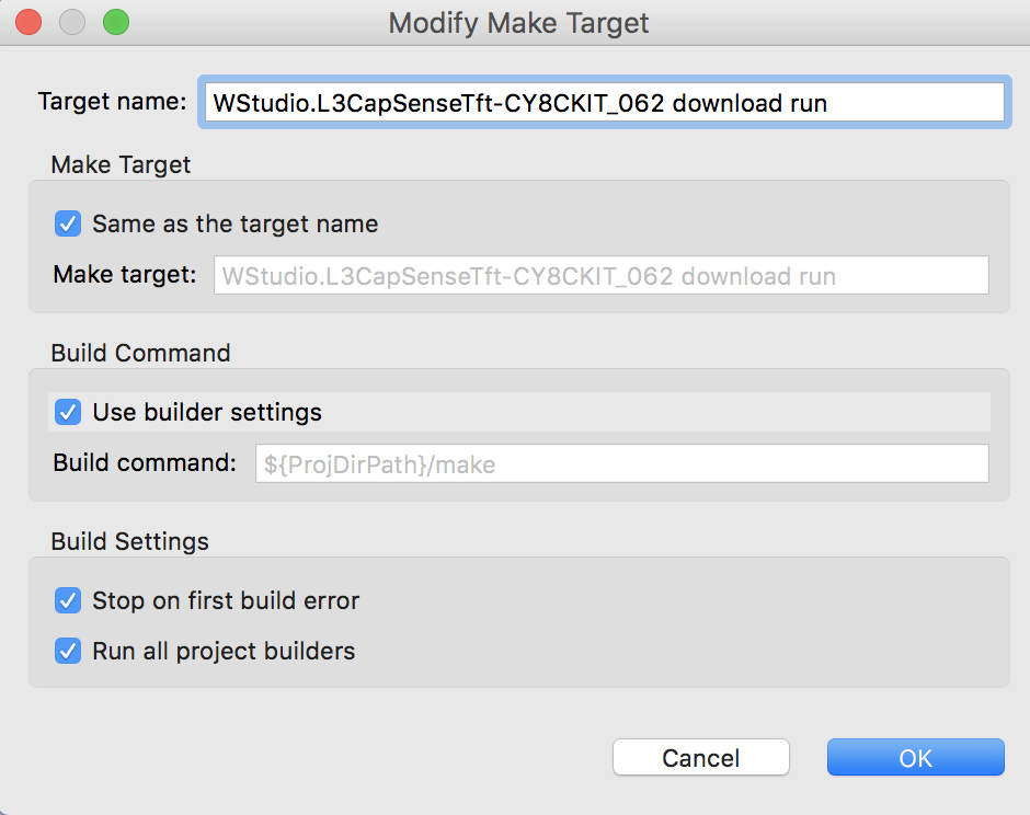
Create a new Make target for the GameBleAws project

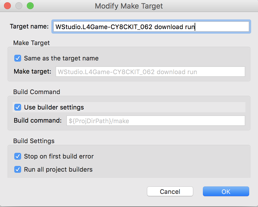
Copy subscriber.c & wifi_config_dct.h

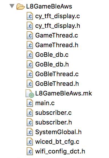
Use copy/paste to make a copy of the subscriber application and paste it into the GameBleAws project.  Once done your folder should look like this:

Update the Makefile

NAME := App_WStudio_L8GameBleAws
$(NAME)_SOURCES := main.c \
CapSenseThread.c \
GameThread.c \
cy_tft_display.c \
GoBleThread.c \
GoBle_db.c \
wiced_bt_cfg.c \
subscriber.c
$(NAME)_COMPONENTS := graphics/ugui \
libraries/drivers/bluetooth/low_energy \
protocols/AWS
WIFI_CONFIG_DCT_H := wifi_config_dct.h
$(NAME)_RESOURCES  := apps/aws/iot/rootca.cer \
apps/aws/iot/subscriber/client.cer \
apps/aws/iot/subscriber/privkey.cer
# To support Low memory platforms, disabling components which are not required
GLOBAL_DEFINES += WICED_CONFIG_DISABLE_SSL_SERVER \
WICED_CONFIG_DISABLE_DTLS \
WICED_CONFIG_DISABLE_ENTERPRISE_SECURITY \
WICED_CONFIG_DISABLE_DES \
WICED_CONFIG_DISABLE_ADVANCED_SECURITY_CURVES

Create subscriber.h

In order for the main.c to know about the awsThread (which is the former application_start of subscriber.c) you should create a file called subscriber.h.  Then you should define the awsThread function to match the wiced_thread_t function prototype (just a function that takes a wiced_thread_arg and returns void).

#pragma once
extern void awsThread( wiced_thread_arg_t arg );

Update main.c

To integrate the awsThread thread into your main project you need to add the “subscriber.h” to the includes:

#include "GameThread.h"
#include "GoBleThread.h"
#include "CapSenseThread.h"
#include "subscriber.h"
#include "wiced.h"

Add a new variable to hold the awsThreadHandle.

wiced_thread_t awsThreadHandle;

Finally you should launch the AWS thread by creating it with wiced_rtos_create_thread.

void application_start( )
{
wiced_init( );
wiced_rtos_init_queue(&paddleQueue,"paddleQueue",sizeof(game_msg_t),10);
wiced_rtos_create_thread(&blinkThreadHandle,7,"Blink Thread",pdlBlinkThread,500,0);
wiced_rtos_create_thread(&capsenseThreadHandle,7,"CapSense Thread",capSenseThread,1024,0);
wiced_rtos_create_thread(&gameThreadHandle,7,"game Thread",gameThread,4096,0);
GoBleThread_start();
wiced_rtos_create_thread(&awsThreadHandle,7,"AWS Thread",awsThread,4096,0);
}

Update subscriber.c

In order for subscriber.c to be useful you need to fix the includes, send the messages from the PADDLE topic to the game thread, and turn application_start into a thread.  Start by fixing the includes (just like we did in the BLE Example in Lesson 6)

#include "SystemGlobal.h"
#include "GameThread.h"

When you get a message to the PADDLE topic, you should parse it, then send a message to the game thread to move the paddle.  You do this exactly the same way as you did in the BLE project.  Notice that I protect the game thread by making sure it send a value less than 100.

        case WICED_AWS_EVENT_PAYLOAD_RECEIVED:
{
uint32_t val;
WPRINT_APP_INFO( ("[Application/AWS] Payload Received[ Topic: %.*s ]:\n", (int)data->message.topic_length, data->message.topic ) );
if(strncmp(WICED_TOPIC,(const char *)data->message.topic,strlen(WICED_TOPIC)) == 0 && data->message.data_length < 4)
{
sscanf((const char *)data->message.data,"%d",(int *)&val);
if(val>100)
val = 100;
WPRINT_APP_INFO(("Val = %d\n",(int)val));
game_msg_t msg;
msg.evt = MSG_POSITION;
msg.val = val;
wiced_rtos_push_to_queue(&paddleQueue,&msg,0);
}
}
break;

Test

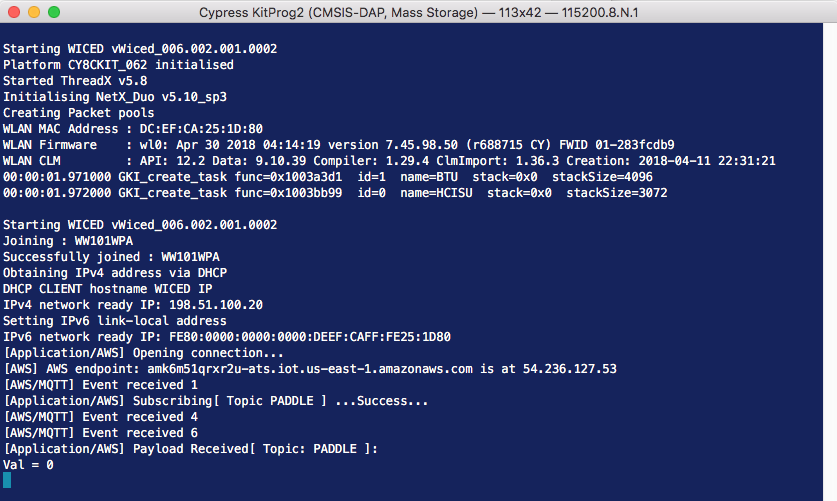
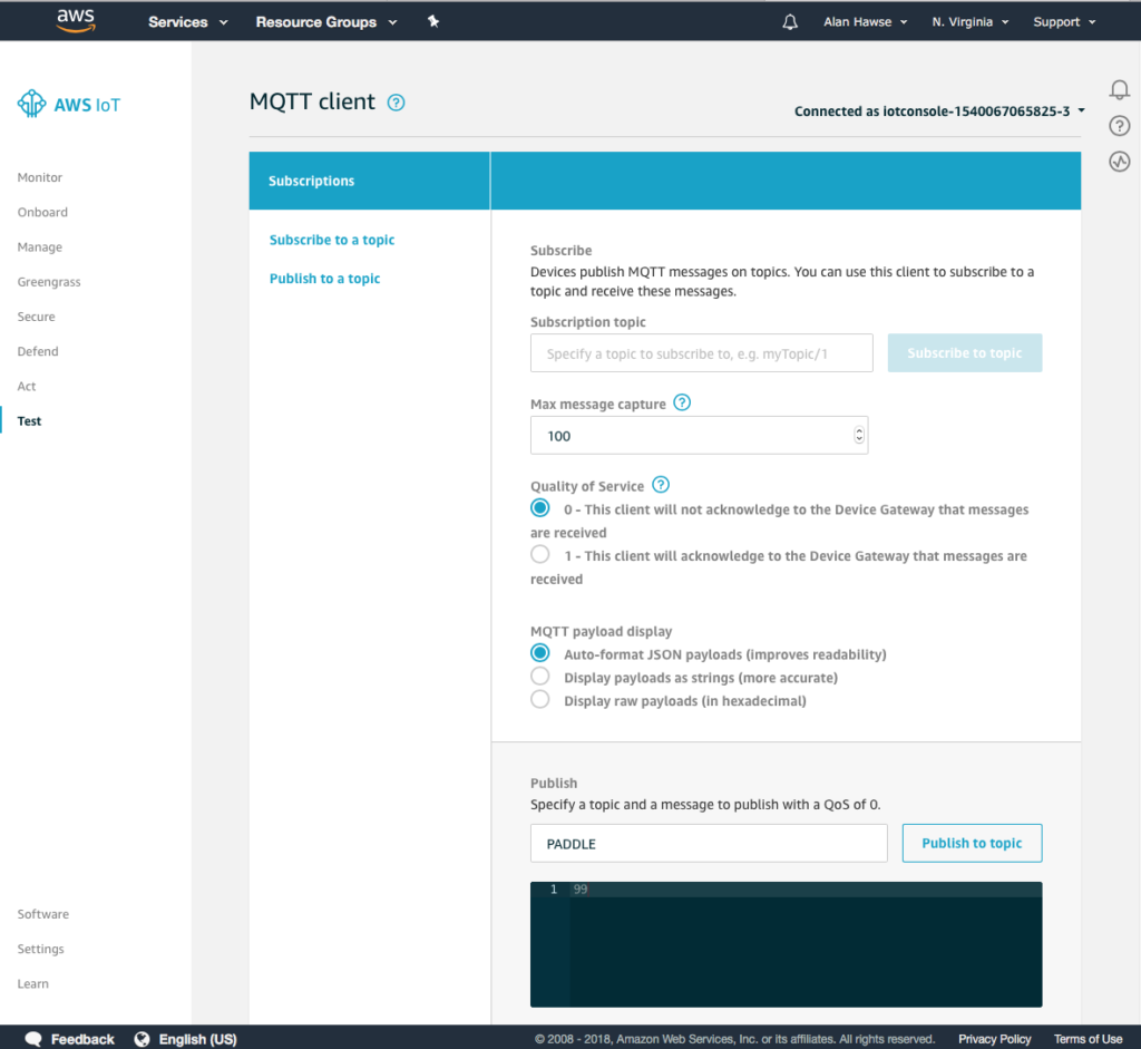
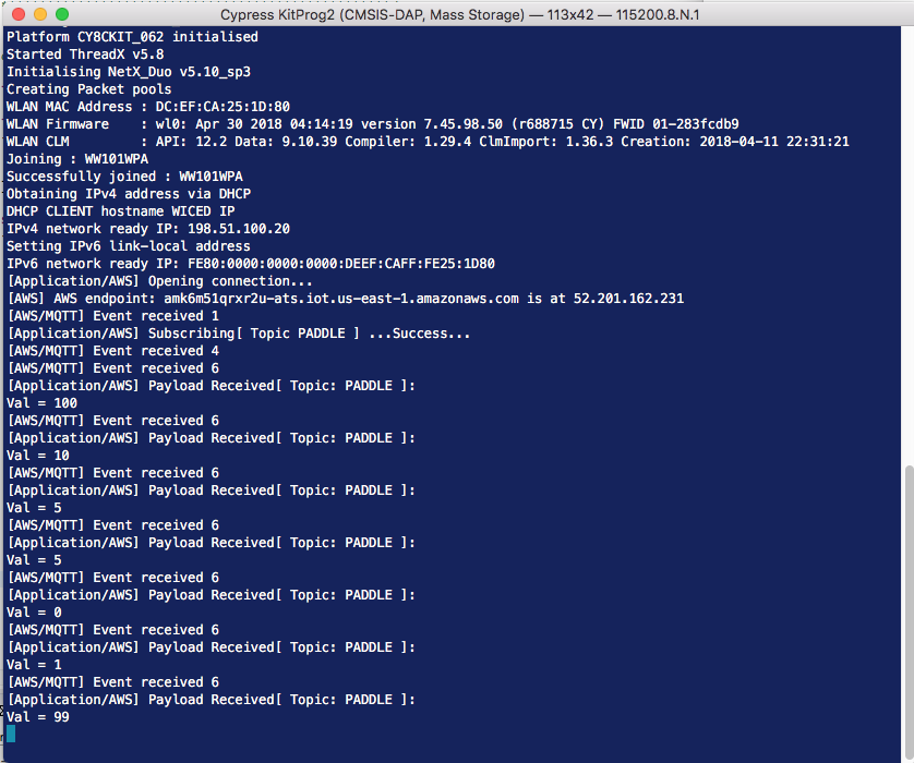
I don’t really have a good program (like the GoBle) to test moving the paddle live.  But you can see that when the game is over, you can still move the paddle using AWS console.  In the screen shot below you can see that I moved the paddle to position 0.  And you can see that the BLE started at the same time as AWS.  Score.

Mouser PSoC 6-WiFi-BT L7 : Implement WiFi and AWS

Designing low-power, cloud-connected IoT devices with PSoC® 6 MCU’s and WICED® Wi-Fi/Bluetooth

Summary

In this lesson I am going to update one of the predefined application which we deliver as part of WICED Studio which knows how to connect to the AWS IoT Cloud to work on my network.  This will demonstrate WiFi and MQTT.  I will also fix the application so that it knows about a new MQTT Topic called “PADDLE” which will be used to send messages to move the game paddle.
To implement this project I will:

  1. Copy the subscriber from demo/aws/iot/pub_sub/subscriber
  2. Setup a “thing” on AWS and download the certificates
  3. Update the certificates in the WICED installation
  4. Update the project with my AWS configuration
  5. Test
  6. Update the project to be compatible with the Game
  7. Test

Copy Subscriber & Fix the Makefile

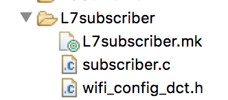
The first thing that I will do is copy/paste the subscriber application which can be found at demo/aws/iot/pub_sub/subscriber into my folder.  I will also rename the project to L7subscriber. Once that is done it should look like this:

Then you need to edit the Makefile to update the name of the project.

NAME := App_WStudio_L7subscriber

Go to Amazon.com and Create a “thing”

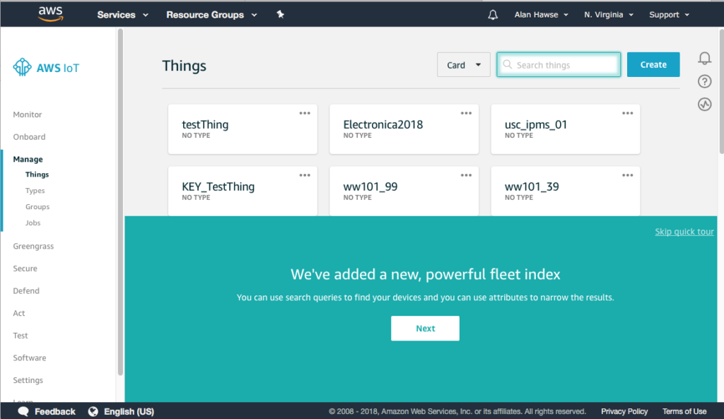
In order to connect to the AWS cloud you need to create a “thing”.  Go to the AWS console and click “Create”

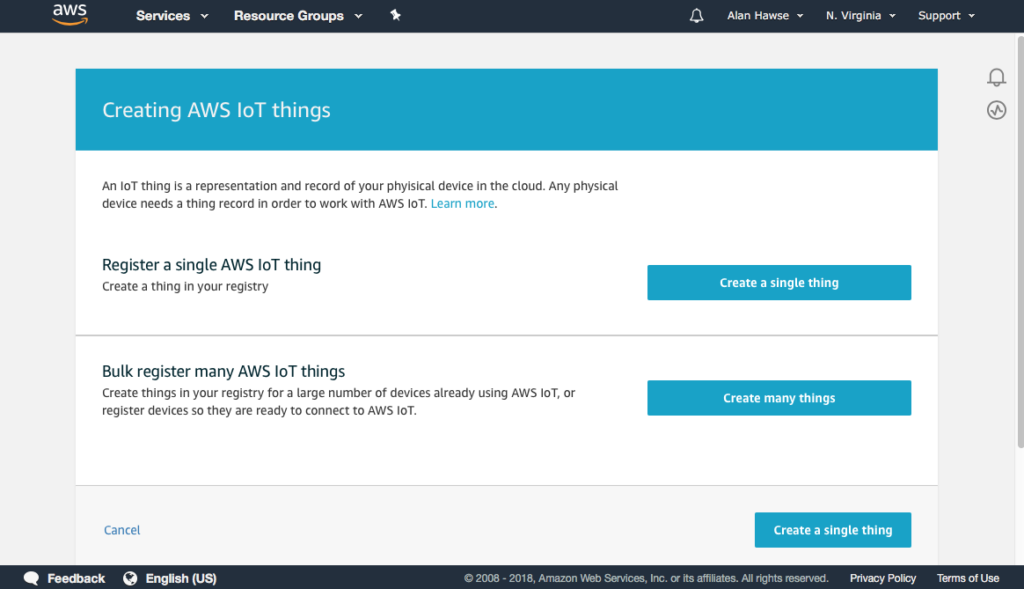
We are just going to create one thing.  So, click “Create a single thing”

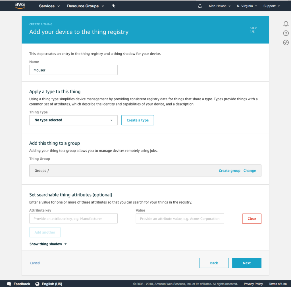
Give it a name, in this case Mouser.

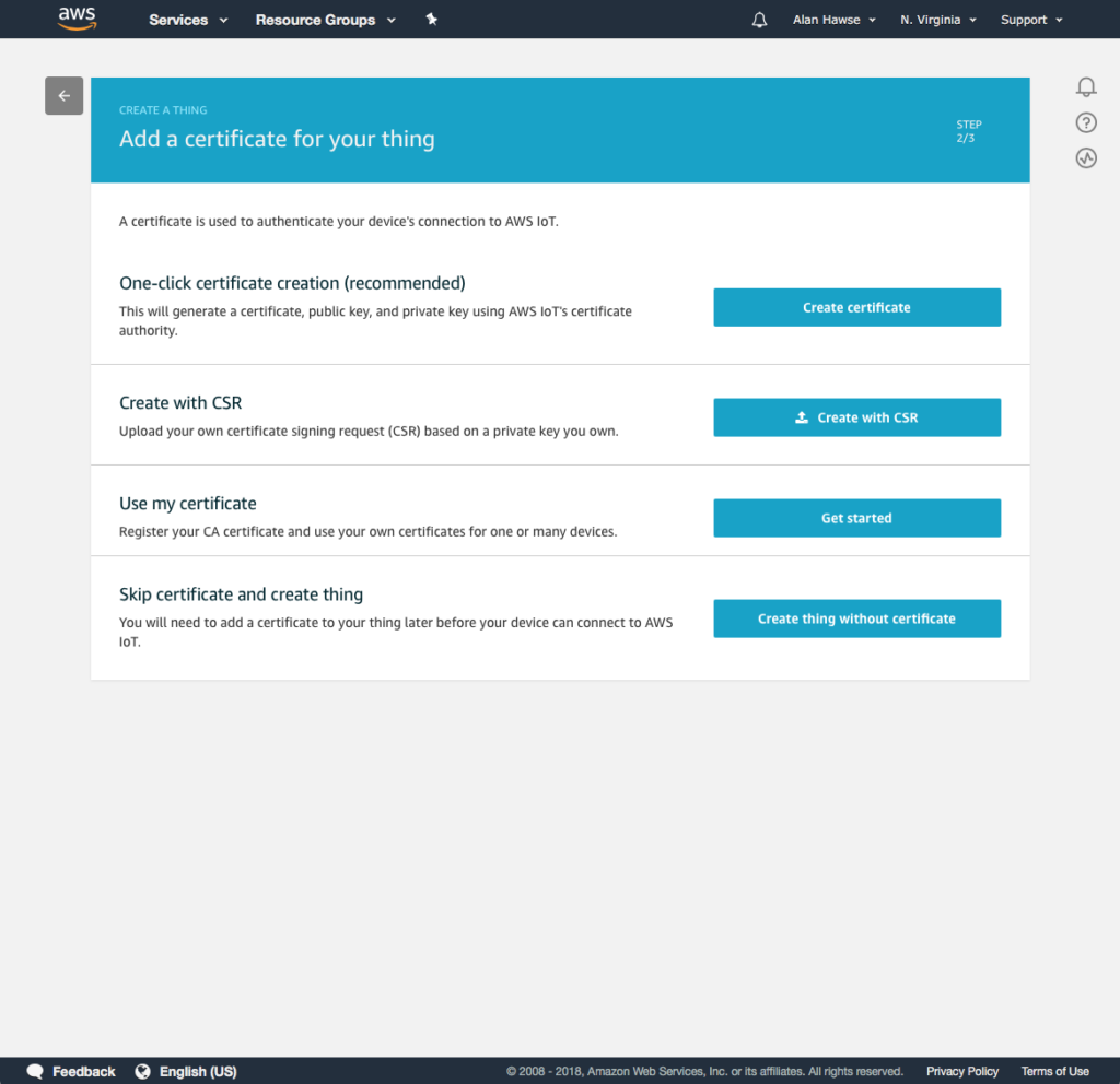
AWS has device level security which is implemented with RSA certificates for each device.  So,  you need to let AWS create a certificate for you.

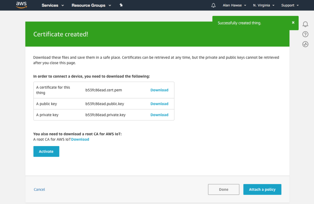
Once that is done download the device certificate and the two keys.  You need to 100% make sure you do this now, because you wont get another chance. I’m also going to activate the certificate once I have the certificate and keys.

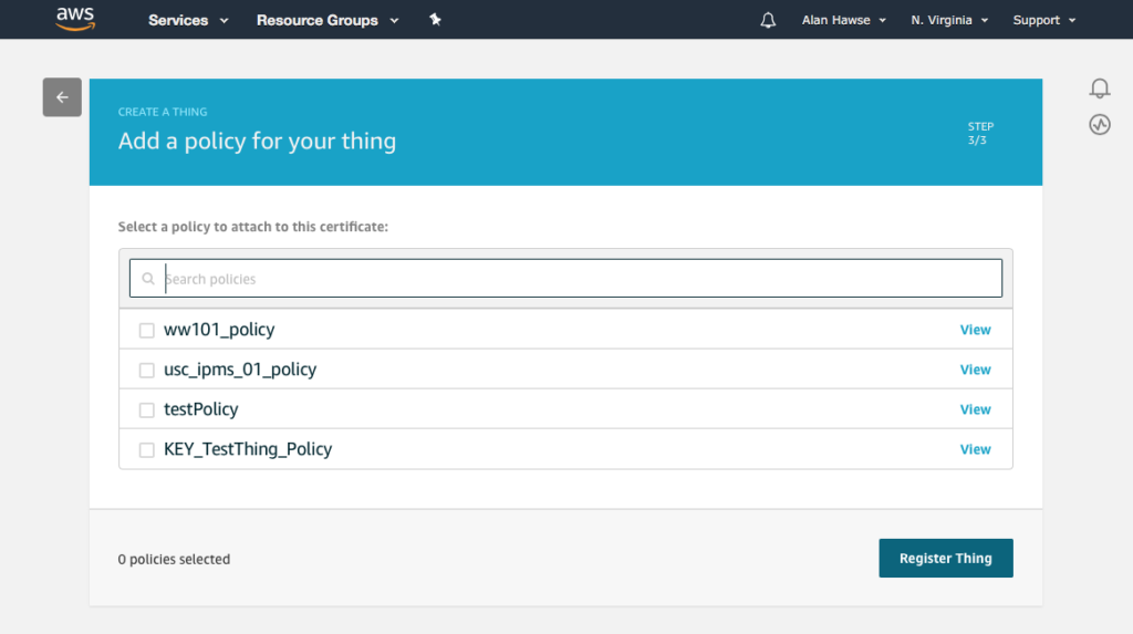
Now attach a policy to your thing.  I already have the “ww101_policy” setup.

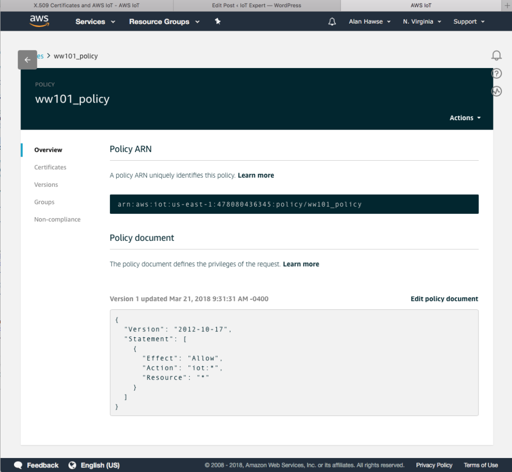
The policy looks like this.  Basically, things are wide open.

Update the Certificates

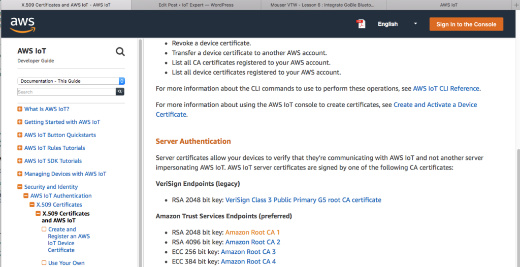
The last thing that you need is the most recent AWS certificate.  WICED expects that you use the RSA2048 bit key.

Now that you have the four security documents., you need to integrate them into your WICED installation.  To do this, change directories to ~/Documents/WICED-Studio-6.2/43xxx_Wi-Fi/resources/apps/aws/iot  Then copy the files, and then make symbolic links.  If you are not on a Mac or Linux then just copy the files and rename them appropriately.

Update the Project

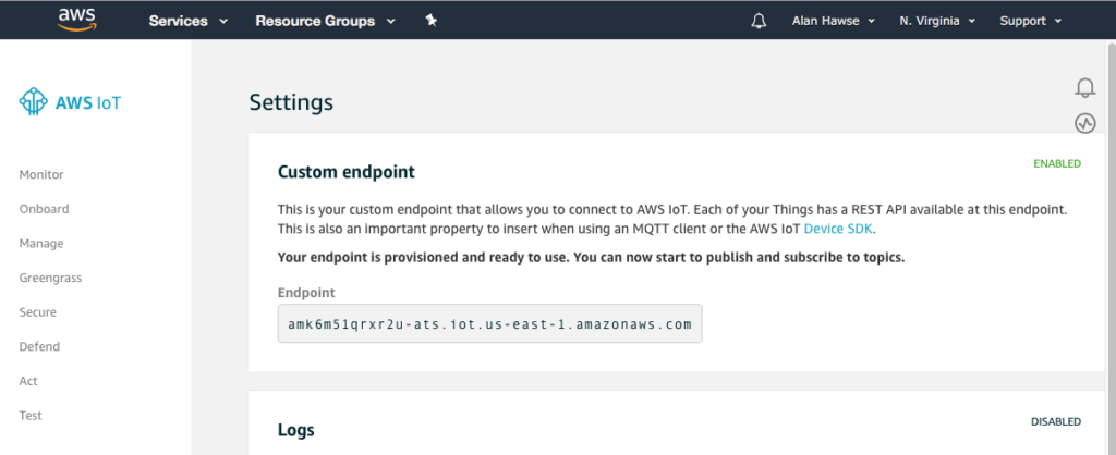
AWS creates a virtual machine and runs an MQTT server on that machine.  You can find out the DNS name of that machine on the settings screen.  Here you can see my endpoint.  You will need to configure the WICED project to talk to your server.

You need to change the actual endpoint of your MQTT server in the AWS cloud on line 119

static wiced_aws_endpoint_info_t my_subscriber_aws_iot_endpoint = {
.transport           = WICED_AWS_TRANSPORT_MQTT_NATIVE,
.uri                 = "amk6m51qrxr2u-ats.iot.us-east-1.amazonaws.com",
.peer_common_name    = NULL,
.ip_addr             = {0},
.port                = WICED_AWS_IOT_DEFAULT_MQTT_PORT,
.root_ca_certificate = NULL,
.root_ca_length      = 0,
};

In the file wifi_config_dct.h you will need to change the CLIENT_AP_SSID and CLIENT_AP_PASSPHRASE for your network

/* This is the default AP the device will connect to (as a client)*/
#define CLIENT_AP_SSID       "WW101WPA"
#define CLIENT_AP_PASSPHRASE "yourpassword"
#define CLIENT_AP_BSS_TYPE   WICED_BSS_TYPE_INFRASTRUCTURE
#define CLIENT_AP_SECURITY   WICED_SECURITY_WPA2_MIXED_PSK
#define CLIENT_AP_CHANNEL    1
#define CLIENT_AP_BAND       WICED_802_11_BAND_2_4GHZ

Test

In order to test the project you will need to create a make target and program your development kit.

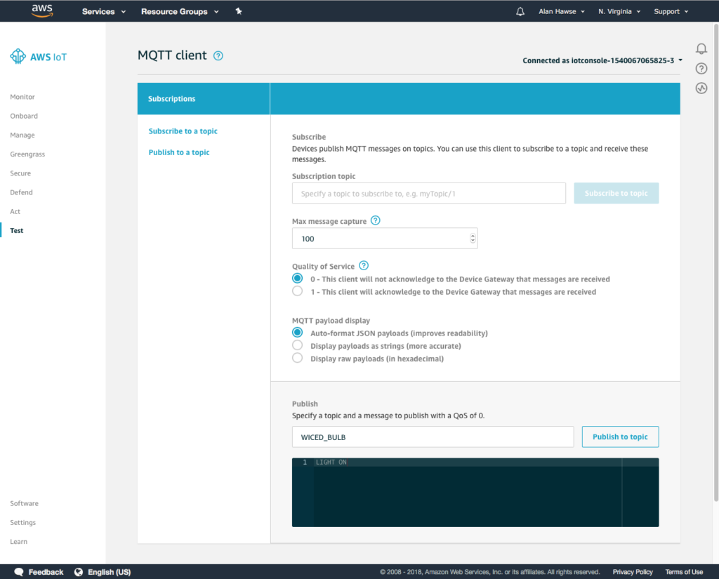
Once that is done you can go to the Amazon.com test console and send MQTT messages to the correct topic.

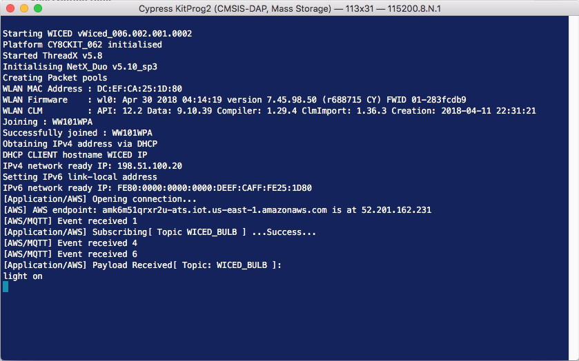
Here you can see the project attached to my network.  And successfully received the LIGHT ON message.

Update the Project for the Game

We know that the game doesn’t care about the LIGHT topic so, let’s change it to PADDLE.

#define WICED_TOPIC                                 "PADDLE"

And let’s assume that messages to the paddle topic are ASCII numbers <100.  So, we can parse the message and print it out.  Notice that I used sscanf to parse the message and we all know that is super dangerous.

        case WICED_AWS_EVENT_PAYLOAD_RECEIVED:
{
char buff[10];
uint32_t val;
WPRINT_APP_INFO( ("[Application/AWS] Payload Received[ Topic: %.*s ]:\n", (int)data->message.topic_length, data->message.topic ) );
if(strncmp(WICED_TOPIC,data->message.topic,strlen(WICED_TOPIC)) == 0 && data->message.data_length < 4)
{
sscanf(data->message.data,"%d",&val);
WPRINT_APP_INFO(("Val = %d\n",val));
}
}
break;

Test

After making those updates let’s program the whole shooting match again.  Then test by sending some messages to the PADDLE topic.

It’s good.  Things are working.

Mouser PSoC6-WiFi-BT L6 : Integrate GoBle Bluetooth into the Game

Designing low-power, cloud-connected IoT devices with PSoC® 6 MCU’s and WICED® Wi-Fi/Bluetooth

Summary

At this point we have a working BLE Remote Control and a working Game.  In this lesson I’ll merge the two projects together so that the GoBle remote control will be able to control the game paddle.  It will do this by creating messages (just like the CapSense messages) and sending them to the Game thread via the paddleQueue.  And it will send “Button0” messages when “Button A” is pressed.

To implement this lesson I will follow these steps:

  1. Copy everything into a new project
  2. Modify the Makefile
  3. Modify main.c
  4. Create a new make target
  5. Test it all to make sure things are still working
  6. Modify GoBleThread.c
  7. Program and Test

Copy L4Game into a new project L6GameBle

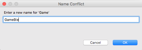
Use “copy” and “paste” to create a new project, when you paste give it the name “L6GameBle” (there is an error in the screenshot)

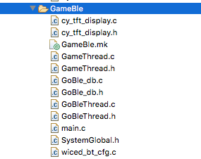
Copy the files GoBle_db.c/h, GoBleThread.c/h, and wiced_bt_cfg.c from the GoBle project into your new GameBle project.  After that is done your project should look like this:

Modify the Makefile

  1. Change the name of the App to “App_WStudio_L6GameBle”
  2. Add the new source files
  3. Add the BLE Library “libraries/drivers/bluetooth/low_energy”
NAME := App_WStudio_L6GameBle
$(NAME)_SOURCES := main.c \
CapSenseThread.c \
GameThread.c \
cy_tft_display.c \
GoBleThread.c \
GoBle_db.c \
wiced_bt_cfg.c
$(NAME)_COMPONENTS := graphics/ugui \
libraries/drivers/bluetooth/low_energy

Modify main.c

Add the include for the GeBleThread.

#include "GameThread.h"
#include "GoBleThread.h"
#include "CapSenseThread.h"
#include "wiced.h"

In the application_start function add a call GoBleThread_start() to get the GoBle thread going

void application_start( )
{
wiced_init( );
wiced_rtos_init_queue(&paddleQueue,"paddleQueue",sizeof(game_msg_t),10);
wiced_rtos_create_thread(&blinkThreadHandle,7,"Blink Thread",pdlBlinkThread,500,0);
wiced_rtos_create_thread(&capSenseThreadHandle,7,"CapSense Thread",capSenseThread,1024,0);
wiced_rtos_create_thread(&gameThreadHandle,7,"game Thread",gameThread,4096,0);
GoBleThread_start();
}

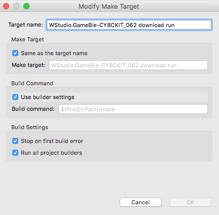
Create a new make target

Test it all to make sure things are still working

Run the make target and make sure that the game still plays and that you can get remote control messages.

Modify GoBleThread.c

Add the includes for the GameThread (to get access to the game message structure) and SystemGlobal (to get access to the queue)

#include "GameThread.h"
#include "SystemGlobal.h"

I don’t need (or want) the button/slider printout information.  So I will delete the old button code from goble_event_handler. (delete this stuff)

            WPRINT_APP_INFO(("# Buttons = %d ButtonMask=%02X Slider x=%02X Slider Y=%02X Raw=",(int)numButtons,(unsigned int)buttonMask,(unsigned int)sliderX,(unsigned int)sliderY));
for(int i=0;i<p_attr_req->data.write_req.val_len;i++)
{
WPRINT_APP_INFO(("%02X ",p_attr_req->data.write_req.p_val[i]));
}
WPRINT_APP_INFO(("\n"));

Now, update the code to send the slider and button information to the GameThread (via the paddleQueue).  You may have noticed that the slider on GoBle gives you 0->0xFF and the direction is the inverse from the game we setup.  So, I will scale the value to 100 and invert it so that the controller moves the paddle the right way on line 143.  The message format is exactly the same as what we setup for the CapSense.  This means the CapSense slider works at the same time as the GoBle controller.

   case GATT_ATTRIBUTE_REQUEST_EVT:
p_attr_req = &p_event_data->attribute_request;
if( p_attr_req->request_type == GATTS_REQ_TYPE_WRITE  && p_attr_req->data.handle == HDLC_GOBLE_SERIALPORTID_VALUE)
{
uint32_t numButtons = p_attr_req->data.write_req.p_val[3];
uint32_t sliderY = p_attr_req->data.write_req.p_val[5+numButtons];
uint32_t sliderX = p_attr_req->data.write_req.p_val[6+numButtons];
uint32_t buttonMask = 0x00;
for(int i=0;i<numButtons;i++)
{
buttonMask |= (1<<p_attr_req->data.write_req.p_val[5+i]);
}
game_msg_t msg;
msg.evt = MSG_POSITION;
msg.val = 100 - (100*sliderY/255);
wiced_rtos_push_to_queue(&paddleQueue,&msg,0);
if(buttonMask & 0x10)
{
msg.evt = MSG_BUTTON0;
msg.val = 1;
wiced_result_t result=wiced_rtos_push_to_queue(&paddleQueue,&msg,0);
}
status = WICED_BT_GATT_SUCCESS;
}
break;

Program and Test

Mouser PSoC6-WiFi-BT L4 : The Video Game

Designing low-power, cloud-connected IoT devices with PSoC® 6 MCU’s and WICED® Wi-Fi/Bluetooth

Summary

In this lesson I’ll finish the video game thread by adding the graphics etc. to play the game.  In addition I’ll fix up the CapSense thread so that it is connected to the game via an RTOS queue.

There are three main things going on in this game.

  1. A state machine for the game screen (Splash, Start, Running, Over)
  2. A 20ms timer that updates the screen while the game is running (moves the Paddle and the Ball)
  3. A GUI queue where the rest of the system – CapSense,  Bluetooth and WiFi – can send Button and Paddle messages.

To implement this project I will:

  1. Setup the project and makefile by copying L3CapSenseTft
  2. Update gamethread.h to define the GUI queue messages
  3. Fix main.c to create the queue
  4. Create SystemGlobal.h to give the rest of the files access to the gui queue
  5. Updating the CapSenseThread to send GUI messages
  6. Update the includes in GameThread.c
  7. Add some #define macros to define game parameters
  8. Add a State Machine for the game & define some paddle movement methods
  9. Make forward declarations for the thread functions
  10. Create some variables to maintain game state
  11. Add display functions for the score and the speed
  12. Add functions to start and end the game
  13. Add helper functions to calculate the top and bottom of the paddle
  14. Add a function to update and draw the paddle
  15. Add a function to update and draw the ball
  16. Add a function for the game timer to call
  17. Update the main game thread

Setup the project and makefile by copying L3CapSenseTft

Use copy/paste to copy the L3CapSenseTft project to a new folder name L4Game.   Change the name of the makefile to be L4Game.mk.

Edit the makefile and change the name of the application.

NAME := App_WStudio_L4Game
$(NAME)_SOURCES := main.c \
CapSenseThread.c \
GameThread.c \
cy_tft_display.c
$(NAME)_COMPONENTS := graphics/ugui

Create a make target for this project

Update GameThread.h to Define the GUI Messages

All of the threads in the system (CapSense, Bluetooth, and WiFi) will control the paddle and the button by sending messages to an RTOS queue.  In gameThread.h we will add a definition of that message.  The message is just a structure with two values – which GUI element and what value to send.

#pragma once
#include "wiced.h"
typedef enum {
MSG_POSITION,
MSG_BUTTON0,
MSG_BUTTON1,
} game_evt_t;
typedef struct {
game_evt_t evt;
uint32_t val;
} game_msg_t;
void gameThread(wiced_thread_arg_t arg);

Fix main.c to Create the Queue

I typically believe that the RTOS primitives should be owned by the main.c.  To do this edit main.c and fix the includes.

#include "GameThread.h"
#include "wiced.h"
#include "CapSenseThread.h"
#include "SystemGlobal.h"

Then define the queue variable “paddleQueue” which I should have names “guiQueue” but it is way to late to fix it now — oh well.

/******************************************************
*               Variable Definitions
******************************************************/
wiced_thread_t blinkThreadHandle;
wiced_thread_t capSenseThreadHandle;
wiced_thread_t gameThreadHandle;
wiced_queue_t paddleQueue;

Create the queue

void application_start( )
{
wiced_init( );
wiced_rtos_init_queue(&paddleQueue,"paddleQueue",sizeof(game_msg_t),10);
wiced_rtos_create_thread(&blinkThreadHandle,7,"Blink Thread",pdlBlinkThread,500,0);
wiced_rtos_create_thread(&capSenseThreadHandle,7,"CapSense Thread",capSenseThread,1024,0);
wiced_rtos_create_thread(&gameThreadHandle,7,"game Thread",gameThread,4096,0);
}

Create SystemGlobal.h

Each of the threads in the system need to have access to the paddleQueue.  In order to do that create a file called SystemGlobal.h and extern the variable to give them that access.

#pragma once
extern wiced_queue_t paddleQueue;

Updating the CapSenseThread to send GUI messages

Remember that when we setup the CapSenseThread originally, it just printed out the values.  Let’s fix it so send messages.  So, edit CapSenseThread.c.

  1. Add a message variable (line 8)
  2. Fix the button0 and button 1 to make and send RTOS messages (lines 20/21 and 26/27)
  3. Fix the slider to send the position (lines 33-35)
#include "wiced.h"
#include "GameThread.h"
#include "SystemGlobal.h"
void capSenseThread(wiced_thread_arg_t arg)
{
game_msg_t msg;
CapSense_Start();
CapSense_ScanAllWidgets();
while(1)
{
if(!CapSense_IsBusy())
{
CapSense_ProcessAllWidgets();
if(CapSense_IsWidgetActive(CapSense_BUTTON0_WDGT_ID))
{
msg.evt = MSG_BUTTON0;
wiced_rtos_push_to_queue(&paddleQueue,&msg,0);
}
if(CapSense_IsWidgetActive(CapSense_BUTTON1_WDGT_ID))
{
msg.evt = MSG_BUTTON1;
wiced_rtos_push_to_queue(&paddleQueue,&msg,0);
}
uint32_t val = CapSense_GetCentroidPos(CapSense_LINEARSLIDER0_WDGT_ID);
if(val < 0xFFFF)
{
msg.evt = MSG_POSITION;
msg.val = val;
wiced_rtos_push_to_queue(&paddleQueue,&msg,0);
}
CapSense_ScanAllWidgets();
}
wiced_rtos_delay_milliseconds(25); // Poll every 25ms (actual scan time ~8ms)
}
}

Update the includes in GameThread.c

Now let’s fix GameThread.c.  Start by editing the includes to add a new file called “SystemGlobal.h” which contains the global variable for the GUI queue.

#include "GameThread.h"
#include "cy_tft_display.h"
#include "SystemGlobal.h"
#include "ugui.h"

Add some #define macros in GameThread.c

There are a number of constants which I use in the game.  In this section I use #define macros to define them.

#define UPDATE_SCREEN_TIME (20) // Update the screen every 20ms
#define SPEED (2)
#define SCREEN_X (320)
#define SCREEN_Y (240)
#define TOP_FIELD (21)
#define PD_WIDTH (10)
#define PD_LEN (70)
#define DOTS (3)
#define PADDLE0_COLOR (C_BLUE)
#define BALL_COLOR (C_GREEN)
#define BALL_SIZE (10)

Add a State Machine for the Game & Define Paddle Movement

Open up GameThread.c – all of the game control functions will go there.

There will be four screens in the game.  A splash screen to display Cypress and Mouser, a Ready Player 1 Screen, the actual game screen and a game over screen.

In addition the paddle can move a little bit at a time (increment) or jump directly to the position (absolute)

// States of the game
typedef enum {
GS_SPLASH,
GS_START,
GS_RUNNING,
GS_OVER
} game_state_t;
// Methods to move the paddle
typedef enum {
PADDLE_INCREMENT,
PADDLE_ABSOLUTE
} paddle_update_t;

Fix the gameState statemachine

In the splash screen I need to set the state machine to GS_SPLASH

static void displaySplashScreen()
{
gameState = GS_SPLASH;
UG_FontSelect( &FONT_22X36 );
UG_PutStringCenter(SCREEN_X/2,SCREEN_Y/5,22,36,"Cypress");
UG_PutStringCenter(SCREEN_X/2,SCREEN_Y/5*2,22,36,"Mouser");
UG_PutStringCenter(SCREEN_X/2,SCREEN_Y/5*3,22,36,"PSoC 6");
UG_PutStringCenter(SCREEN_X/2,SCREEN_Y/5*4,22,36,"WICED 4343");
wiced_rtos_delay_milliseconds(2000);
}

In the start screen I need to set the state machine to GS_START

// Display the Start Screen
static void  displayStartScreen()
{
gameState = GS_START;
UG_FillScreen( C_BLACK );
UG_FontSelect( &FONT_22X36 );
UG_PutStringCenter(SCREEN_X/2,SCREEN_Y/2 -2 - 18 ,22,36,"Ready");
UG_PutStringCenter(SCREEN_X/2,SCREEN_Y/2 + 2 + 18 ,22,36,"Player 1");
displayStartButton();
}

Make Forward Declarations for Functions

You should define the functions in advance of using them

/******************************************************
*               Static Function Declarations
******************************************************/
static void UG_PutStringCenter(uint32_t x, uint32_t y, uint32_t fontx, uint32_t fonty,char *string);
static void displaySplashScreen();
static void displayStartButton();
static void  displayStartScreen();
static void displayScore();
static void displaySpeed();
static void endGame();
static inline uint32_t calcPaddleTop();
static inline uint32_t calcPaddleBottom();
static void updatePaddle(paddle_update_t type);
static void updateBall();
static void updateScreen(void *arg);

Create some variables to maintain game state

The updateScreenTimer is used while the game is running to call the updateScreen every 20ms.  The rest of the variables are self explanatory.

/******************************************************
*               Variable Definitions
******************************************************/
static UG_GUI   gui;
static wiced_timer_t updateScreenTimer;
static uint32_t gameScore;
static game_state_t gameState;
// position of the paddle
static uint32_t paddle0_desire_pos=0;
static uint32_t paddle0_cur_pos=0;
// Position, direction and speed of the ball
static uint32_t ballx,bally;
static int32_t ballXdir, ballYdir;
static uint32_t ballSpeed;

Add Display Functions for the Score & Speed

These two functions print the speed and score at the top of the screen.

// This function displays the score
static void displayScore()
{
char buff[10];
sprintf(buff,"%2X",(unsigned int)gameScore);
UG_FontSelect(&FONT_12X20);
UG_PutString( 75, 0, buff);
}
// This function displays the speed
static void displaySpeed()
{
char buff[10];
sprintf(buff,"%2X",(unsigned int)ballSpeed-1);
UG_FontSelect(&FONT_12X20);
UG_PutString( 275, 0, buff);
}

Add Function to Start the Game

When the game needs to start you:

  1. Reset the score
  2. Set the paddle position
  3. Move the ball to the middle of the paddle
  4. Set the ball to move to the right and down
  5. Clear the screen, display score and speed
  6. Start the game running
// This function initializes everything and starts a new game
static void startGame()
{
gameScore = 0;
paddle0_desire_pos = 50; // start the game with the paddle moving
paddle0_cur_pos = 0;
ballx = PD_WIDTH ;                   // start the ball on the paddle on the right of the screen
bally  = calcPaddleTop() + PD_LEN/2; // start the ball in the middle of the paddle
ballSpeed = SPEED;
ballXdir = ballSpeed;
ballYdir = ballSpeed;
UG_FillScreen( C_BLACK );  // clear screen
UG_FontSelect(&FONT_12X20);
UG_PutString( 0, 0,  "Score:");
displayScore();
UG_PutString(200,0,"Speed:");
displaySpeed();
UG_DrawLine(0,20,SCREEN_X,20,C_RED); // red line under text to represent top of play screen
gameState = GS_RUNNING;
wiced_rtos_start_timer(&updateScreenTimer); // Timer to update screen
}

Add Function to End the Game

When the game is over you should:

  1. Move the game state to over
  2. Stop the timer
  3. Display game over
  4. Display press button 0 to start
// Stop the game
static void endGame()
{
gameState = GS_OVER;
wiced_rtos_stop_timer(&updateScreenTimer);
UG_FontSelect( &FONT_22X36 );
UG_PutStringCenter(SCREEN_X/2,SCREEN_Y/2,22,36,"Game Over");
displayStartButton();
}

Add Helper Functions to Calculate Paddle Top & Bottom

There are two places where you need to know the position of the Paddle.  Specifically:

  1. To draw the paddle
  2. To figure out if the ball hit the paddle or not.

These two functions calculate the pixel position of the top and bottom of the paddle based on it current position

// Figure out the y position of the top of the paddle
static inline uint32_t calcPaddleTop()
{
return (paddle0_cur_pos)*DOTS+TOP_FIELD;
}
// Figure out the y position of the bottom of the paddle
static inline uint32_t calcPaddleBottom()
{
return (paddle0_cur_pos)*DOTS+PD_LEN+TOP_FIELD;
}

Add a Function to Update & Draw the Paddle

While the game is running you need the paddle to move.  There are two methods:

  1. Absolute just moves the current position immediately to the desired position.
  2. Incremental, which moves the paddle a little bit towards the desired position.
// Move the paddle either to : PADDLE_INCREMENT the next location or PADDLE_ABSOLUTE - final location
static void updatePaddle(paddle_update_t type)
{
// If the paddle is where it is supposed to be then just return
if(paddle0_cur_pos == paddle0_desire_pos)
return;
// erase the current paddle
UG_FillFrame(0,calcPaddleTop(),PD_WIDTH,calcPaddleBottom(),C_BLACK);
switch (type)
{
case PADDLE_INCREMENT:
if(paddle0_cur_pos < paddle0_desire_pos)
paddle0_cur_pos += SPEED;
else
paddle0_cur_pos -= SPEED;
// If the paddle is within one move of the final spot, put it there
if(abs((int)paddle0_cur_pos-(int)paddle0_desire_pos) < SPEED)
paddle0_cur_pos = paddle0_desire_pos;
break;
case PADDLE_ABSOLUTE:
paddle0_cur_pos = paddle0_desire_pos;
break;
}
// draw the paddle
UG_FillFrame(0,calcPaddleTop(),PD_WIDTH,calcPaddleBottom(),PADDLE0_COLOR);
}

Add a function to update and draw the ball

You need a function to:

  1. Move the ball
  2. Figure out if it hit the right/left/top/bottom of the screen and do the right thing.

When the ball hits one of those surfaces it needs to change direction to either plus or minus.

Every time it hits the paddle the score should increase and possibly speed up.

If it misses the paddle the game is over.

// Move the ball to the next location
static void updateBall()
{
static const uint32_t BallFudgeFactor=3;
UG_DrawCircle(ballx,bally,BALL_SIZE,C_BLACK);
ballx += ballXdir;
bally += ballYdir;
// Check to see if the ball hit the far right side
if(ballx > SCREEN_X - BALL_SIZE)
{
ballx = SCREEN_X - BALL_SIZE;
ballXdir = -ballSpeed;
}
// check to see if the ball hit the far left side... or the paddle
if(ballx < (BALL_SIZE + PD_WIDTH + BallFudgeFactor))
{
// See if the ball missed the paddle
if(bally + BALL_SIZE < calcPaddleTop() || bally - BALL_SIZE > calcPaddleBottom())
{
endGame();
//WPRINT_APP_INFO(("Missed Paddle\r\n"));
}
gameScore = gameScore + 1;
displayScore();
if(gameScore % 3 == 0) // Speed up every three hits
{
ballSpeed +=1;
displaySpeed();
}
ballx = BALL_SIZE + PD_WIDTH + BallFudgeFactor;
ballXdir = +ballSpeed;
}
// Check to see if the ball hit the top or bottom
if(bally > SCREEN_Y - BALL_SIZE) // bottom
{
bally = SCREEN_Y - BALL_SIZE;
ballYdir = -ballSpeed;
}
if(bally < TOP_FIELD+BALL_SIZE) // top
{
bally = BALL_SIZE+TOP_FIELD;
ballYdir = +ballSpeed;
}
UG_DrawCircle(ballx,bally,BALL_SIZE,BALL_COLOR);
}

Create a Function for the Game Timer

An RTOS timer runs every 20ms.  That timer needs a function to move the paddle and move the ball.

// This function is called every UPADTE_SCREEN_TIME milliseconds by the updateScreenTimer
static void updateScreen(void *arg)
{
updatePaddle(PADDLE_INCREMENT);
updateBall();
}

Update the Main Game Thread

The main game thread needs to get messages out of the queue and then do the right thing based on the game state.

// Main game thread
void gameThread(wiced_thread_arg_t arg)
{
game_msg_t msg;
Cy_TFT_Init();                                             // Init the TFT
UG_Init( &gui, Cy_TFT_displayDriver, SCREEN_X, SCREEN_Y ); // Connect the driver
UG_FillScreen( C_BLACK );   // Clear the screen
UG_SetBackcolor( C_BLACK );
UG_SetForecolor( C_WHITE );
wiced_rtos_init_timer(&updateScreenTimer,UPDATE_SCREEN_TIME,updateScreen,0);
displaySplashScreen();
displayStartScreen();
while(1)
{
wiced_rtos_pop_from_queue(&paddleQueue,&msg,WICED_WAIT_FOREVER);
switch(msg.evt)
{
case MSG_POSITION:
if(gameState == GS_RUNNING)
paddle0_desire_pos = msg.val/2;
if(gameState == GS_OVER)
{
paddle0_desire_pos = msg.val/2;
updatePaddle(PADDLE_ABSOLUTE);
}
break;
case MSG_BUTTON0:
if(gameState == GS_OVER || gameState == GS_START)
startGame();
break;
case MSG_BUTTON1:
break;
}
}
}

Program and Test

Now that it is all done… program and test it.

GameThread.c

Here is the whole thread is here so you can copy/paste it into your file.

#include "GameThread.h"
#include "cy_tft_display.h"
#include "SystemGlobal.h"
#include "ugui.h"
/******************************************************
*                      Macros
******************************************************/
#define UPDATE_SCREEN_TIME (20) // Update the screen every 20ms
#define SPEED (2)
#define SCREEN_X (320)
#define SCREEN_Y (240)
#define TOP_FIELD (21)
#define PD_WIDTH (10)
#define PD_LEN (70)
#define DOTS (3)
#define PADDLE0_COLOR (C_BLUE)
#define BALL_COLOR (C_GREEN)
#define BALL_SIZE (10)
/******************************************************
*                    Constants
******************************************************/
/******************************************************
*                   Enumerations
******************************************************/
/******************************************************
*                 Type Definitions
******************************************************/
// States of the game
typedef enum {
GS_SPLASH,
GS_START,
GS_RUNNING,
GS_OVER
} game_state_t;
// Methods to move the paddle
typedef enum {
PADDLE_INCREMENT,
PADDLE_ABSOLUTE
} paddle_update_t;
/******************************************************
*                    Structures
******************************************************/
/******************************************************
*               Static Function Declarations
******************************************************/
static void UG_PutStringCenter(uint32_t x, uint32_t y, uint32_t fontx, uint32_t fonty,char *string);
static void displaySplashScreen();
static void displayStartButton();
static void  displayStartScreen();
static void displayScore();
static void displaySpeed();
static void endGame();
static inline uint32_t calcPaddleTop();
static inline uint32_t calcPaddleBottom();
static void updatePaddle(paddle_update_t type);
static void updateBall();
static void updateScreen(void *arg);
/******************************************************
*               Variable Definitions
******************************************************/
static UG_GUI   gui;
static wiced_timer_t updateScreenTimer;
static uint32_t gameScore;
static game_state_t gameState;
// position of the paddle
static uint32_t paddle0_desire_pos=0;
static uint32_t paddle0_cur_pos=0;
// Position, direction and speed of the ball
static uint32_t ballx,bally;
static int32_t ballXdir, ballYdir;
static uint32_t ballSpeed;
/******************************************************
*               Functions
******************************************************/
// ARH Function to put text in the center of a point (UG_PutString does upper left)
static void UG_PutStringCenter(uint32_t x, uint32_t y, uint32_t fontx, uint32_t fonty,char *string)
{
y = y - fonty/2;
x = x - (strlen(string)/2)*fontx;
if(strlen(string)%2)
x = x - fontx/2;
UG_PutString(x,y,string);
}
// Display the splash screen
static void displaySplashScreen()
{
gameState = GS_SPLASH;
UG_FontSelect( &FONT_22X36 );
UG_PutStringCenter(SCREEN_X/2,SCREEN_Y/5,22,36,"Cypress");
UG_PutStringCenter(SCREEN_X/2,SCREEN_Y/5*2,22,36,"Mouser");
UG_PutStringCenter(SCREEN_X/2,SCREEN_Y/5*3,22,36,"PSoC 6");
UG_PutStringCenter(SCREEN_X/2,SCREEN_Y/5*4,22,36,"WICED 4343");
wiced_rtos_delay_milliseconds(2000);
}
// This function displays the start button message
static void displayStartButton()
{
UG_FontSelect(&FONT_12X20);
UG_PutStringCenter(SCREEN_X/2 , SCREEN_Y - 30 ,12,22,  "Press B0 To Start");
}
// Display the Start Screen
static void  displayStartScreen()
{
gameState = GS_START;
UG_FillScreen( C_BLACK );
UG_FontSelect( &FONT_22X36 );
UG_PutStringCenter(SCREEN_X/2,SCREEN_Y/2 -2 - 18 ,22,36,"Ready");
UG_PutStringCenter(SCREEN_X/2,SCREEN_Y/2 + 2 + 18 ,22,36,"Player 1");
displayStartButton();
}
// This function displays the score
static void displayScore()
{
char buff[10];
sprintf(buff,"%2X",(unsigned int)gameScore);
UG_FontSelect(&FONT_12X20);
UG_PutString( 75, 0, buff);
}
// This function displays the speed
static void displaySpeed()
{
char buff[10];
sprintf(buff,"%2X",(unsigned int)ballSpeed-1);
UG_FontSelect(&FONT_12X20);
UG_PutString( 275, 0, buff);
}
// This function initializes everything and starts a new game
static void startGame()
{
gameScore = 0;
paddle0_desire_pos = 50; // start the game with the paddle moving
paddle0_cur_pos = 0;
ballx = PD_WIDTH ;                   // start the ball on the paddle on the right of the screen
bally  = calcPaddleTop() + PD_LEN/2; // start the ball in the middle of the paddle
ballSpeed = SPEED;
ballXdir = ballSpeed;
ballYdir = ballSpeed;
UG_FillScreen( C_BLACK );  // clear screen
UG_FontSelect(&FONT_12X20);
UG_PutString( 0, 0,  "Score:");
displayScore();
UG_PutString(200,0,"Speed:");
displaySpeed();
UG_DrawLine(0,20,SCREEN_X,20,C_RED); // red line under text to represent top of play screen
gameState = GS_RUNNING;
wiced_rtos_start_timer(&updateScreenTimer); // Timer to update screen
}
// Stop the game
static void endGame()
{
gameState = GS_OVER;
wiced_rtos_stop_timer(&updateScreenTimer);
UG_FontSelect( &FONT_22X36 );
UG_PutStringCenter(SCREEN_X/2,SCREEN_Y/2,22,36,"Game Over");
displayStartButton();
}
// Figure out the y position of the top of the paddle
static inline uint32_t calcPaddleTop()
{
return (paddle0_cur_pos)*DOTS+TOP_FIELD;
}
// Figure out the y position of the bottom of the paddle
static inline uint32_t calcPaddleBottom()
{
return (paddle0_cur_pos)*DOTS+PD_LEN+TOP_FIELD;
}
// Move the paddle either to : PADDLE_INCREMENT the next location or PADDLE_ABSOLUTE - final location
static void updatePaddle(paddle_update_t type)
{
// If the paddle is where it is supposed to be then just return
if(paddle0_cur_pos == paddle0_desire_pos)
return;
// erase the current paddle
UG_FillFrame(0,calcPaddleTop(),PD_WIDTH,calcPaddleBottom(),C_BLACK);
switch (type)
{
case PADDLE_INCREMENT:
if(paddle0_cur_pos < paddle0_desire_pos)
paddle0_cur_pos += SPEED;
else
paddle0_cur_pos -= SPEED;
// If the paddle is within one move of the final spot, put it there
if(abs((int)paddle0_cur_pos-(int)paddle0_desire_pos) < SPEED)
paddle0_cur_pos = paddle0_desire_pos;
break;
case PADDLE_ABSOLUTE:
paddle0_cur_pos = paddle0_desire_pos;
break;
}
// draw the paddle
UG_FillFrame(0,calcPaddleTop(),PD_WIDTH,calcPaddleBottom(),PADDLE0_COLOR);
}
// Move the ball to the next location
static void updateBall()
{
static const uint32_t BallFudgeFactor=3;
UG_DrawCircle(ballx,bally,BALL_SIZE,C_BLACK);
ballx += ballXdir;
bally += ballYdir;
// Check to see if the ball hit the far right side
if(ballx > SCREEN_X - BALL_SIZE)
{
ballx = SCREEN_X - BALL_SIZE;
ballXdir = -ballSpeed;
}
// check to see if the ball hit the far left side... or the paddle
if(ballx < (BALL_SIZE + PD_WIDTH + BallFudgeFactor))
{
// See if the ball missed the paddle
if(bally + BALL_SIZE < calcPaddleTop() || bally - BALL_SIZE > calcPaddleBottom())
{
endGame();
//WPRINT_APP_INFO(("Missed Paddle\r\n"));
}
gameScore = gameScore + 1;
displayScore();
if(gameScore % 3 == 0) // Speed up every three hits
{
ballSpeed +=1;
displaySpeed();
}
ballx = BALL_SIZE + PD_WIDTH + BallFudgeFactor;
ballXdir = +ballSpeed;
}
// Check to see if the ball hit the top or bottom
if(bally > SCREEN_Y - BALL_SIZE) // bottom
{
bally = SCREEN_Y - BALL_SIZE;
ballYdir = -ballSpeed;
}
if(bally < TOP_FIELD+BALL_SIZE) // top
{
bally = BALL_SIZE+TOP_FIELD;
ballYdir = +ballSpeed;
}
UG_DrawCircle(ballx,bally,BALL_SIZE,BALL_COLOR);
}
// This function is called every UPADTE_SCREEN_TIME milliseconds by the updateScreenTimer
static void updateScreen(void *arg)
{
updatePaddle(PADDLE_INCREMENT);
updateBall();
}
// Main game thread
void gameThread(wiced_thread_arg_t arg)
{
game_msg_t msg;
Cy_TFT_Init();                                             // Init the TFT
UG_Init( &gui, Cy_TFT_displayDriver, SCREEN_X, SCREEN_Y ); // Connect the driver
UG_FillScreen( C_BLACK );   // Clear the screen
UG_SetBackcolor( C_BLACK );
UG_SetForecolor( C_WHITE );
wiced_rtos_init_timer(&updateScreenTimer,UPDATE_SCREEN_TIME,updateScreen,0);
displaySplashScreen();
displayStartScreen();
while(1)
{
wiced_rtos_pop_from_queue(&paddleQueue,&msg,WICED_WAIT_FOREVER);
switch(msg.evt)
{
case MSG_POSITION:
if(gameState == GS_RUNNING)
paddle0_desire_pos = msg.val/2;
if(gameState == GS_OVER)
{
paddle0_desire_pos = msg.val/2;
updatePaddle(PADDLE_ABSOLUTE);
}
break;
case MSG_BUTTON0:
if(gameState == GS_OVER || gameState == GS_START)
startGame();
break;
case MSG_BUTTON1:
break;
}
}
}


Mouser PSoC 6-WiFi-BT L3: Using the CY8CKIT-028-TFT Shield

Designing low-power, cloud-connected IoT devices with PSoC® 6 MCU’s and WICED® Wi-Fi/Bluetooth

Summary

In this lesson we will start making the game.  The first thing that it will need is a display and we will use the CY8CKIT-028-TFT.  In order to talk to the display we will use a library built into WICED called ugui.  That library needs a driver configuration which we will copy of out the code example we provide.  Finally we will start building a thread called the “GameThread” which will actually make up the game.

  1. Download CE222494_PSoC6_WICED_WiFi
  2. Copy the L2CapSense into L3CapSenseTft
  3. Copy cy_tft_display.c/h into the project
  4. Make a file GameThread.h
  5. Make a file GameThread.c
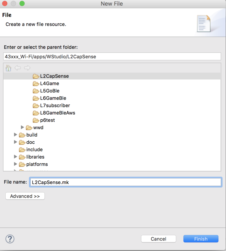
  6. Rename L2CapSense.mk to be L3CapSenseTft.mk & Fix
  7. Update main.c
  8. Test

Download CE222494_PSoC6_WICED_WiFi

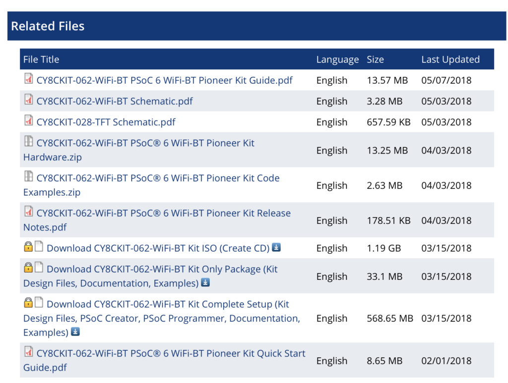
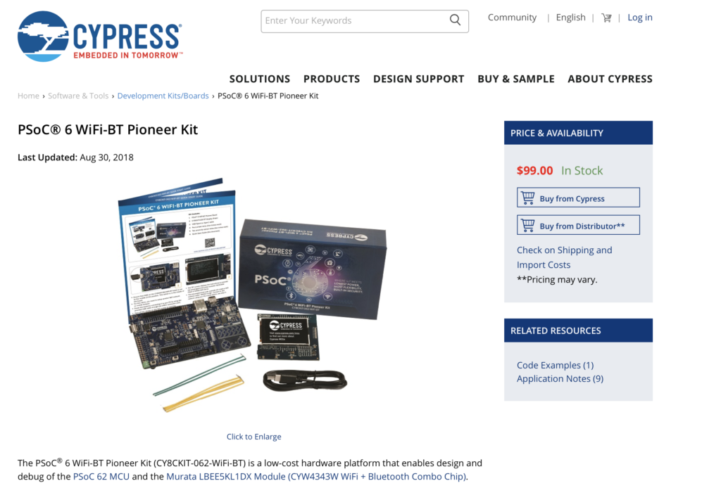
If you click on the CY8CKIT-062-WiFi-BT webpage you will find that there are a bunch of files which are associated with the development kit, including CY8CKIT-062-WiFi-BT PSoC® 6 WiFi-BT Pioneer Kit Code Examples.zip.

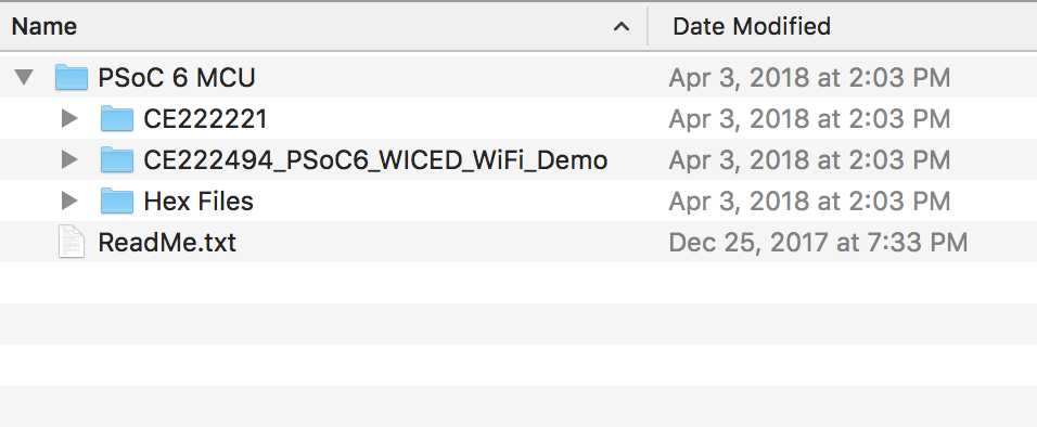
Download that folder, then copy the directory into your WICED Studio Apps/WStudio folder.

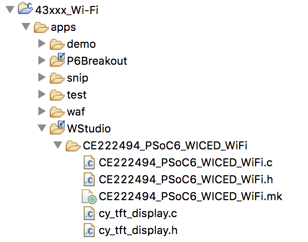
Once you do that it should look like this:

Copy L3CapSense into L3CapSenseTft

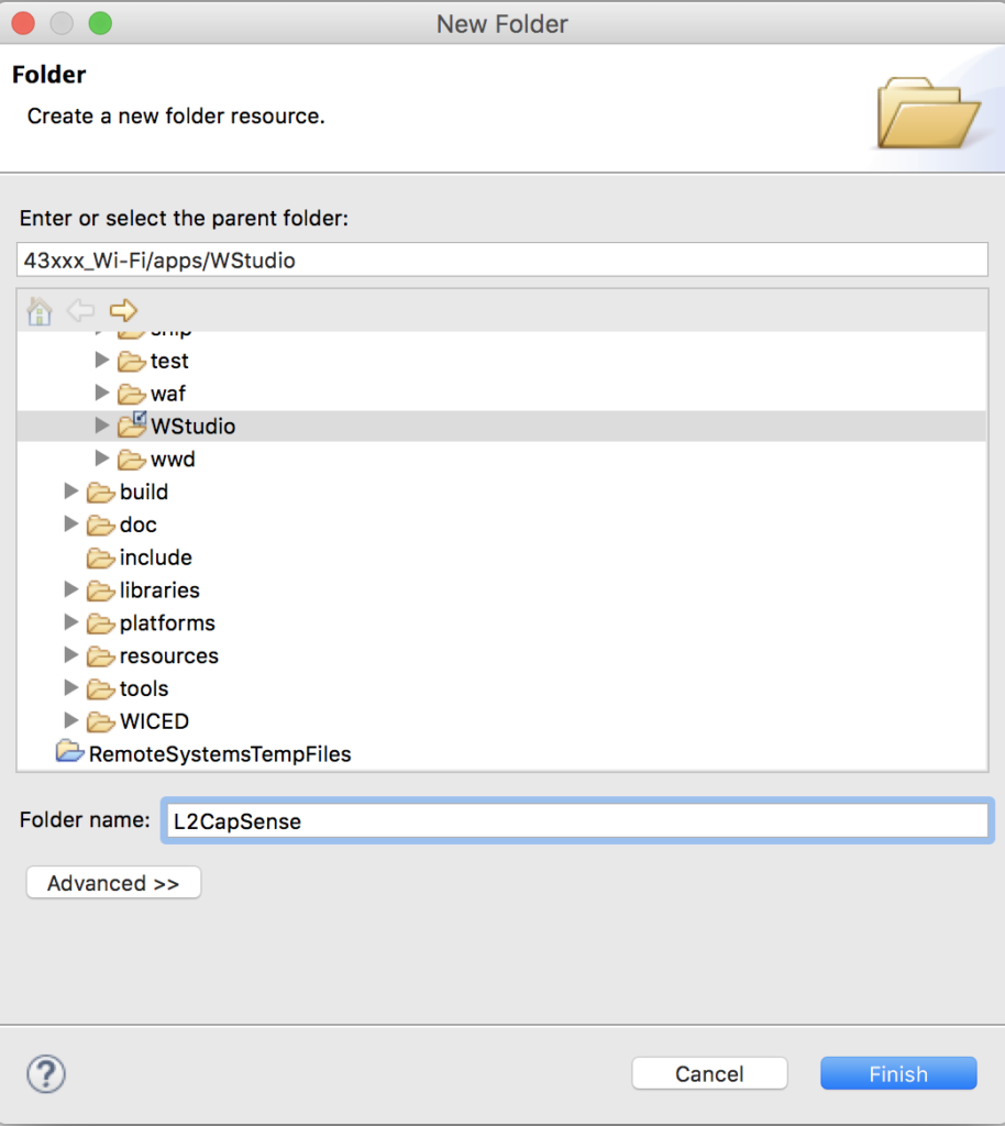
Now copy/paste the L2CapSense project into a new project called L3CapSenseTft

Copy cy_tft_display.c/h into the project

Open up the CE222494 code example directory and copy the two files cy_tft_display.c andcy_tft_display.c which are drivers for the ugui library and then paste them into your new project L3CapSenseTft.

Make a file GameThread.h

Create a new file called GamThread.h and a definition of the GameThread which will be used by the main.c to get the game thread going.

#pragma once
#include "wiced.h"
void gameThread(wiced_thread_arg_t arg);

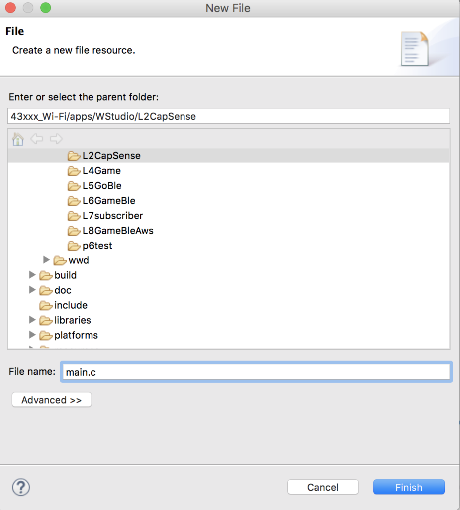
Make a file GameThread.c

Now create a file called GameThread.c it will have 5 functions.  Here is the whole file to make it simpler to copy and paste, but Ill explain each function one by one

#include "GameThread.h"
#include "cy_tft_display.h"
#define SCREEN_X (320)
#define SCREEN_Y (240)
static UG_GUI   gui;
// ARH Function to put text in the center of a point (UG_PutString does upper left)
static void UG_PutStringCenter(uint32_t x, uint32_t y, uint32_t fontx, uint32_t fonty,char *string)
{
y = y - fonty/2;
x = x - (strlen(string)/2)*fontx;
if(strlen(string)%2)
x = x - fontx/2;
UG_PutString(x,y,string);
}
// Display the splash screen
static void displaySplashScreen()
{
UG_FontSelect( &FONT_22X36 );
UG_PutStringCenter(SCREEN_X/2,SCREEN_Y/5,22,36,"Cypress");
UG_PutStringCenter(SCREEN_X/2,SCREEN_Y/5*2,22,36,"Mouser");
UG_PutStringCenter(SCREEN_X/2,SCREEN_Y/5*3,22,36,"PSoC 6");
UG_PutStringCenter(SCREEN_X/2,SCREEN_Y/5*4,22,36,"WICED 4343");
wiced_rtos_delay_milliseconds(2000);
}
// This function displays the start button message
static void displayStartButton()
{
UG_FontSelect(&FONT_12X20);
UG_PutStringCenter(SCREEN_X/2 , SCREEN_Y - 30 ,12,22,  "Press B0 To Start");
}
// Display the Start Screen
static void  displayStartScreen()
{
UG_FillScreen( C_BLACK );
UG_FontSelect( &FONT_22X36 );
UG_PutStringCenter(SCREEN_X/2,SCREEN_Y/2 -2 - 18 ,22,36,"Ready");
UG_PutStringCenter(SCREEN_X/2,SCREEN_Y/2 + 2 + 18 ,22,36,"Player 1");
displayStartButton();
}
// Main game thread
void gameThread(wiced_thread_arg_t arg)
{
Cy_TFT_Init();                                             // Init the TFT
UG_Init( &gui, Cy_TFT_displayDriver, SCREEN_X, SCREEN_Y ); // Connect the driver
UG_FillScreen( C_BLACK );   // Clear the screen
UG_SetBackcolor( C_BLACK );
UG_SetForecolor( C_WHITE );
displaySplashScreen();
displayStartScreen();
while(1)
{
wiced_rtos_delay_milliseconds(1000);
}
}

The main game thread function is: void gameThread(wiced_thread_arg_t arg).  This function

  1. Initializes the TFT
  2. Initializes the UGUI library
  3. Clears the screen (by setting it all black)
  4. Sets the colors to draw white on black
  5. Displays the splash screen (which takes 2 seconds)
  6. Displays the start screen
  7. Waits until the end of time
// Main game thread
void gameThread(wiced_thread_arg_t arg)
{
Cy_TFT_Init();                                             // Init the TFT
UG_Init( &gui, Cy_TFT_displayDriver, SCREEN_X, SCREEN_Y ); // Connect the driver
UG_FillScreen( C_BLACK );   // Clear the screen
UG_SetBackcolor( C_BLACK );
UG_SetForecolor( C_WHITE );
displaySplashScreen();
displayStartScreen();
while(1)
{
wiced_rtos_delay_milliseconds(1000);
}
}

The function displaySplashScreen simply sets the font, then draws 4 text strings, then waits for a few seconds… then moves on

// Display the splash screen
static void displaySplashScreen()
{
UG_FontSelect( &FONT_22X36 );
UG_PutStringCenter(SCREEN_X/2,SCREEN_Y/5,22,36,"Cypress");
UG_PutStringCenter(SCREEN_X/2,SCREEN_Y/5*2,22,36,"Mouser");
UG_PutStringCenter(SCREEN_X/2,SCREEN_Y/5*3,22,36,"PSoC 6");
UG_PutStringCenter(SCREEN_X/2,SCREEN_Y/5*4,22,36,"WICED 4343");
wiced_rtos_delay_milliseconds(2000);
}

The displayStartScreen put the “Ready Player 1 on the screen” and then tells the user to press the B0 to start the game.

// This function displays the start button message
static void displayStartButton()
{
UG_FontSelect(&FONT_12X20);
UG_PutStringCenter(SCREEN_X/2 , SCREEN_Y - 30 ,12,22,  "Press B0 To Start");
}
// Display the Start Screen
static void  displayStartScreen()
{
UG_FillScreen( C_BLACK );
UG_FontSelect( &FONT_22X36 );
UG_PutStringCenter(SCREEN_X/2,SCREEN_Y/2 -2 - 18 ,22,36,"Ready");
UG_PutStringCenter(SCREEN_X/2,SCREEN_Y/2 + 2 + 18 ,22,36,"Player 1");
displayStartButton();
}

The U8G_PutString function uses coordinates x and y to set the upper left of the text.  For formatting purposes it is easier for me to think about the middle of the string.  This function just calculates the upper left (x,y) given the middle center (x,y).  To do this you need to also know the (x,y) size of the font.

static void UG_PutStringCenter(uint32_t x, uint32_t y, uint32_t fontx, uint32_t fonty,char *string)

// ARH Function to put text in the center of a point (UG_PutString does upper left)
static void UG_PutStringCenter(uint32_t x, uint32_t y, uint32_t fontx, uint32_t fonty,char *string)
{
y = y - fonty/2;
x = x - (strlen(string)/2)*fontx;
if(strlen(string)%2)
x = x - fontx/2;
UG_PutString(x,y,string);
}

Rename L2CapSense.mk to be L3CapSenseTft.mk & Fix

To make this build we need to modify the makefile to know about the new thread as well as the tft driver.  In addition we need to tell the linker to link with the graphics library.

NAME := App_WStudio_L3CapSenseTft
$(NAME)_SOURCES := 	main.c \
CapSenseThread.c \
GameThread.c \
cy_tft_display.c
$(NAME)_COMPONENTS := graphics/ugui

Update main.c

In main.c I will:

  1. Include the GameThread.h
  2. Add a variable to hold the gameThreadHandle
  3. Then start the gameThread
#include "wiced.h"
#include "CapSenseThread.h"
#include "GameThread.h"
/******************************************************
*                      Macros
******************************************************/
/******************************************************
*                    Constants
******************************************************/
/******************************************************
*                   Enumerations
******************************************************/
/******************************************************
*                 Type Definitions
******************************************************/
/******************************************************
*                    Structures
******************************************************/
/******************************************************
*               Static Function Declarations
******************************************************/
/******************************************************
*               Variable Definitions
******************************************************/
wiced_thread_t blinkThreadHandle;
wiced_thread_t capSenseThreadHandle;
wiced_thread_t gameThreadHandle;
/******************************************************
*               Function Definitions
******************************************************/
void pdlBlinkThread(wiced_thread_arg_t arg)
{
while(1)
{
Cy_GPIO_Inv(GPIO_PRT0,3);
wiced_rtos_delay_milliseconds(500);
}
}
void application_start( )
{
wiced_init();
WPRINT_APP_INFO(("Started Application\n"));
wiced_rtos_create_thread(&blinkThreadHandle,7,"Blink Thread",pdlBlinkThread,500,0);
wiced_rtos_create_thread(&capSenseThreadHandle,7,"CapSense Thread",capSenseThread,1024,0);
wiced_rtos_create_thread(&gameThreadHandle,7,"game Thread",gameThread,4096,0);
}

Test

Now it is ready to test.  So create a Make Target, then Build and Program.  Hopefully you are now Ready Player 1.


Mouser PSoC 6-WiFi-BT L2 : WICED Studio & CapSense

Designing low-power, cloud-connected IoT devices with PSoC® 6 MCU’s and WICED® Wi-Fi/Bluetooth

Summary

In this lesson we will build your first WICED Studio project (the blinking LED)  and make sure that you can program the development kit.  Then we will update the project to include a thread for managing the CapSense block.  This thread will be carried into the other projects.

To implement this lesson I will follow these steps:

  1. Start WICED Studio 6.2
  2. Select 43xxx
  3. Create a folder called L2CapSense
  4. Create main.c and build a blinking LED thread
  5. Create L2CapSense.mk
  6. Create a make target
  7. Build Program and test it
  8. Create CapSenseThread.c
  9. Create CapSenseThread.h
  10. Update main.c
  11. Update the makefile
  12. Build Program and Test

Create the L2CapSense Folder

Create main.c

Right click on the folder and create a new file.  Name it L2CapSense

Insert the blinking LED code into main.c

#include "wiced.h"
/******************************************************
*                      Macros
******************************************************/
/******************************************************
*                    Constants
******************************************************/
/******************************************************
*                   Enumerations
******************************************************/
/******************************************************
*                 Type Definitions
******************************************************/
/******************************************************
*                    Structures
******************************************************/
/******************************************************
*               Static Function Declarations
******************************************************/
/******************************************************
*               Variable Definitions
******************************************************/
wiced_thread_t blinkThreadHandle;
/******************************************************
*               Function Definitions
******************************************************/
void pdlBlinkThread(wiced_thread_arg_t arg)
{
while(1)
{
Cy_GPIO_Inv(GPIO_PRT0,3);
wiced_rtos_delay_milliseconds(500);
}
}
void application_start( )
{
WPRINT_APP_INFO(("Started Application\n"));
wiced_rtos_create_thread(&blinkThreadHandle,7,"Blink Thread",pdlBlinkThread,500,0);
}

Create L2CapSense.mk

Create a makefile called L2CapSense.mk

Put the build information into the L2CapSense.mk

NAME := App_WStudio_L2CapSense
$(NAME)_SOURCES := 	main.c

Create a Make Target to run the project

Build and Test the Blinking LED

Create/Edit a File called CapSenseThread.c

#include "wiced.h"
void capSenseThread(wiced_thread_arg_t arg)
{
CapSense_Start();
CapSense_ScanAllWidgets();
while(1)
{
if(!CapSense_IsBusy())
{
CapSense_ProcessAllWidgets();
if(CapSense_IsWidgetActive(CapSense_BUTTON0_WDGT_ID))
{
WPRINT_APP_INFO(("Button 0 Active\n"));
}
if(CapSense_IsWidgetActive(CapSense_BUTTON1_WDGT_ID))
{
WPRINT_APP_INFO(("Button 1 Active\n"));
}
uint32_t val = CapSense_GetCentroidPos(CapSense_LINEARSLIDER0_WDGT_ID);
if(val < 0xFFFF)
{
WPRINT_APP_INFO(("Slider = %d\n",(int)val));
}
CapSense_ScanAllWidgets();
}
wiced_rtos_delay_milliseconds(25); // Poll every 25ms (actual scan time ~8ms)
}
}

Create/Edit a File Called CapSenseThread.h

#pragma once
#include "wiced.h"
void capSenseThread(wiced_thread_arg_t arg);

Update main.c

#include "wiced.h"
#include "CapSenseThread.h"

Add a variable to hold the handle for the capSenseThread at the top of main.c

wiced_thread_t capSenseThreadHandle;

Update the main function to start the CapSenseThread

void application_start( )
{
WPRINT_APP_INFO(("Started Application\n"));
wiced_rtos_create_thread(&blinkThreadHandle,7,"Blink Thread",pdlBlinkThread,500,0);
wiced_rtos_create_thread(&capSenseThreadHandle,7,"CapSense Thread",capSenseThread,1024,0);
}

Update the L2CapsenseThread.mk

NAME := App_WStudio_L2CapSense
$(NAME)_SOURCES := 	main.c \
CapSenseThread.c

Build, Program and Test the CapSenseThread


Mouser PSoC 6-WiFi-BT L1 : Developer Resources

Designing low-power, cloud-connected IoT devices with PSoC® 6 MCU’s and WICED® Wi-Fi/Bluetooth

Summary

This is an index of links to all of the PSoC 6 & CYW4343W learning resources.  You can click the links to go the website or see screen captures of the resources.

  1. PSoC 6 Product Page
  2. WiFi + Bluetooth Combo Product Page
  3. PSoC 6 Documentation
  4. PSoC 6 Community
  5. Wireless Combo Community
  6. CY8CKIT-062-BT-WiFi Development Kit Product Page
  7. CY8CKIT-062-BT-WiFi Development Kit Guide
  8. PSoC 6 Datasheet
  9. CYW4343W Datasheet
  10. PSoC 6 Technical Reference Manuals
  11. PSoC 6 Application Notes
  12. WiFi + Bluetooth Combo Application Notes
  13. PSoC 6 Code Examples
  14. Video Tutorials
  15. PSoC 6 Knowledge Base
  16. Peripheral Driver Library Documentation (Doxygen)
  17. WICED Documentation

PSoC 6 Product Page

You can find the PSoC 6 Product landing page for PSoC 6 here

WiFi + Bluetooth Combo Page

PSoC 6 Documentation

On the PSoC 6 Product Landing page there is a documentation tab that has links to all of the current documentation.

PSoC 6 Community

Cypress has an active development community and forum.  It can be found here.

Wireless WiFi + Bluetooth Combo Community

CY8CKIT-062-WiFi-BT Development Kit Web Page

Every Cypress development kit has a web page that contains all of the information about it, including links to the documentation and store.  The CY8CKIT-062-WiFi-BT kit page is here.

CY8CKIT-062-WiFi-BT Development Kit Guide

You can find the development kit guide here.


PSoC 6 Datasheet

The PSoC 6 Datasheet is available on Cypress.com here.


CYW4343W Datasheet

The CYW4343W datasheet can be found here.

PSoC 6 Technical Reference Manual

Each of the PSoC 6 devices has a lengthy discussion of the Technical Resources.  These documents can be found here

PSoC 6 Application Notes

You can get them all on our website… here is a link to the filtered list of PSoC 6 Application Notes.

The best application note is always the “Getting Started”.  In this case it is AN210781 “Getting Started with PSoC 6 MCU with Bluetooth Low Energy (BLE) Connectivity”

WiFi + Bluetooth Combo Application Notes

Here is a link to all of the WiFI Bluetooth Combo Application Notes.

PSoC 6 Code Examples

You can find all of the PSoC 6 code examples on the web.  In addition they are built into PSoC Creator.

Or in PSoC Creator:

Videos

Cypress has made a bunch of videos that take you step by step through an introduction to PSoC 6.  You can find them on the Cypress training website.

PSoC 6 Knowledge Base

The Cypress technical support team writes “Knowledge Base” articles when there are repeated issues reported by customers.  You can find them here.

Peripheral Driver Library Documentation (Doxygen)

All of the APIs in the PDL are documented in a Doxygen generated HTML document.  You can get there from

  • Help -> Peripheral Driver Library (this link is live only when you have a PSoC 6 project open)
  • Right click on a component -> Open PDL Documentation

Particle Photon Configuration with Tinker Firmware

Summary

In the last article I wrote about using a CY3280 MBR3 Shield on a WICED WiFI 943907AEVAL1F development kit at the GE MegaHackathon.  In the next article I will show you the WICED HTTP firmware that I wrote to connect to the Particle Photon which they were using (I have written about Particle Photon before).  Obviously, I like Particle Photon because it is a WICED 43362 WiFi Radio.  In this article, I am going to show you how to get a Particle Photon going with the Tinker firmware.  Then test it with the iOS app, the web console and finally using CURL.  The CURL is just a mechanism to send HTTP Posts to the Tinker firmware, exactly what I will do in the next article on the WICED development kit.

Configure the Particle Photon

When you get a fresh Particle Photon out of the box you need to get it introduced to your WiFi network, and attached to your console.  To do this, start by going to setup.particle.io and following the process.

Particle Photon Configuration


Particle Photon Configuration

Particle Photon Configuration

Particle Photon Configuration

Particle Photon Configuration

Particle Photon Configuration


Particle Photon Configuration


Particle Photon Configuration

Testing with iPhone App

One you have “claimed” your Particle Photon and it is connected to the network, then you can talk to it with the Particle iOS app.  Here is what it looked like when I started the App on my phone.  You can see the device called “iotexpert-example” (remember that is what I named it from above).  The “Elkhorn_creek” Photon is the one that I wrote about in this article.

Particle Photon iOS App

Although the console says that I have the Tinker Firmware on the app, I wanted to make sure, so I use the iOS App to re-flash the Tinker Firmware.  You can do this by clicking the new device, then press the little “…” at the top right of the screen.  Finally click “Reflash Tinker”. It is awesome how fast that happens.

Particle Photon iOS Flash Firmware

Once I am sure about the version of the Tinker firmware, I test to make sure that things are working correctly.  First I click on “D7”

Particle Photon iOS Tinker App

Which brings up this screen where you can select digitalRead and digitalWrite.

Particle Photon iOS Tinker App

Then when you press the button it will switch from high to low and vice versa.

Particle Photon iOS Tinker App Particle Photon iOS Tinker App

You can also call the API directly by pressing “inspect” then “Data”

Particle Photon iOS digitalwrite Data Function

Particle Photon Console

In addition to using the iOS App, you can also interact with the Photon using the console.

Particle Photon Console

When I click on the “iotexpert-example” it brings up this screen where I can run the Tinker firmware functions.  In this case I ran “digitialwrite” with “D7,HIGH” which turns on the LED on the Photon.

Particle Photon Console

Testing the Particle Photon with CURL

The Particle Cloud exposes an API which lets you send Restful API requests to specific devices.  The Unix tool CURL lets me type command line requests (which I will mimic in the next Article using WICED).  The first command that I send is and HTTP GET which will return a JSON document that describes the configuration on my Photon.

curl https://api.particle.io/v1/devices/iotexpert-example?access_token=1311f67269d6

You can see the device name etc in the JSON below.  It also shows that the Tinker firmware has four function built into it.

{  
"id":"2a001b000347353137323334",
"name":"iotexpert-example",
"last_app":null,
"last_ip_address":"69.23.226.142",
"last_heard":"2017-09-17T15:38:56.406Z",
"product_id":6,
"connected":true,
"platform_id":6,
"cellular":false,
"notes":null,
"status":"normal",
"current_build_target":"0.5.3",
"variables":{  
},
"functions":[  
"digitalread",
"digitalwrite",
"analogread",
"analogwrite"
]
}

Then I can send a HTTP POST using Curl to turn on the D7 LED.

 curl https://api.spark.io/v1/devices/2a001b000347354/digitalwrite -d access_token=1311f67269d66b -d params=D7,HIGH

You can see the Blue LED right next to D7 turns on.

Particle Photon

Particle Photon Tinker App

I wondered where the Tinker App API was documented?  It turns out that the App is available in Particle library.  You can search by typing “tinker”

The section of code that matters is here.  The function takes a “String” and parses it.  It demands that the 2nd character be a PIN number between 0 and 7.  The first character be a capital “D”.  Then you need to have a “HIGH” (in caps) or a “LOW” (in caps)

/*******************************************************************************
* Function Name  : tinkerDigitalWrite
* Description    : Sets the specified pin HIGH or LOW
* Input          : Pin and value
* Output         : None.
* Return         : 1 on success and a negative number on failure
*******************************************************************************/
int tinkerDigitalWrite(String command)
{
bool value = 0;
//convert ascii to integer
int pinNumber = command.charAt(1) - '0';
//Sanity check to see if the pin numbers are within limits
if (pinNumber< 0 || pinNumber >7) return -1;
if(command.substring(3,7) == "HIGH") value = 1;
else if(command.substring(3,6) == "LOW") value = 0;
else return -2;
if(command.startsWith("D"))
{
pinMode(pinNumber, OUTPUT);
digitalWrite(pinNumber, value);
return 1;
}
else if(command.startsWith("A"))
{
pinMode(pinNumber+10, OUTPUT);
digitalWrite(pinNumber+10, value);
return 1;
}
else return -3;
}

In order to access the digitialwrite function via the network, they publish it (and some others).

/***
* All the based tinker functions are registered. You can add you own code.
***/
// This #include statement was automatically added by the Spark IDE.
#include "Tinker.h"
void setup() {
//Register all the Tinker functions
Spark.function("digitalread", tinkerDigitalRead);
Spark.function("digitalwrite", tinkerDigitalWrite);
Spark.function("analogread", tinkerAnalogRead);
Spark.function("analogwrite", tinkerAnalogWrite);
}
void loop() {
}

When I first thought about the Tinker firmware I thought that it must be reasonably complex.  But it is not because it takes advantage of the Particle cloud functionality.  All in all what they did is very elegant and simple..

Now that it looks like my Particle Photon is working, in the next article I will show you WICED firmware to read the CapSense buttons and then Turn On/Off the LED on the Photon.

CY3280 MBR3 & WICED CYW943907

Summary

In the last Article I talked about the GE Megahackathon.  One of the groups at the event got interested in using a CY3280 MBR3 to send signals via a WICED CYW943907 to the Particle IO server which was connected to a Particle Photon.  I helped them with the implementation and thought that it would be useful to show here.

CYW3280 & WICED CYW943907

Cypress CY3280 MBR3

The CY3280 MBR development kit is a CapSense demonstration kit that shows the Mechanical Button Replacement 3 chip.  It features 4 CapSense buttons with LEDs, a proximity sensor, and a buzzer.  It is connected to another MCU via the Arduino pins. of the WICED CYW943907.  The device sits on the I2C bus and acts as an I2C Slave.  You configure it using EZ Click.

When you run EZ Click you can setup the configure the internal registers of the MBR3 to make the board act like a bunch of different things.  In this case I turned on

  • The MBR buttons 1-4 (you can see them in the picture above)
  • The Flanking Sensor rejection which makes it so that you can only press one button at a time.
  • All of the automatic tuning features.

EZ-Click CY3280

Once the main CapSense is configured, I moved to the other part of the configuration where I setup

  • The 4 LEDs to toggle and be full brightness when on
  • The buzzer to buzz for 100ms at 4kHz when something happens
  • The host interrupt pin as CS15/SH/HI.  This made the Arduino pin D2 be an interrupt when something happened so that WICED would poll the MBR3

EZ-Click CY3280

Once these settings were all done, I downloaded the firmware configuration via the KitProg USB connector.  Then I tested it using the bridge control panel which I have shown you a bunch of different times in the past.  The MBR3 acts as an I2C slave.  To find out what the state of the buttons are you need to read register 0xAA.  The only little trick is that the chip goes to sleep to save power.  In order to wake it up you need to send an I2C transaction, which ends up getting NAK’d.  But the next transaction you send will be ACKd.  In the screenshot below you can see that I tried two of the buttons (0x08 and 0x20)

Bridge Control Panel

One problem that I had is that the power system of this board is setup to take 5V from the Arduino base board but the WICED development kit gives only 3.3v.  Here is a picture of the power system from the MBR3 schematic.

CY3280 Power Supply

The MBR3 can run on 3.3Vs.  In fact it can run all the way down to 1.7v and up to 5.5v, but for some reason (which I can’t remember) we made the board only work with 5.0v.  To fix this problem I removed J12 and then wired a wire from the 3.3V Arduino pin.  The wire is soldered onto the 3.3v pin, but has a female connector on the other side so that it can be plugged into J12.  Here is a picture:

CY3280

The last thing that I needed to do was move the jumpers to position “A” which made the host interrupt pin be connected to D2, and move the I2C jumpers so that the MBR3 was connected to the Arduino instead of the P5LP kitprog.  You can see that in the J3_scl and J3_sda in the picture above.

WICED CYW943907

The CYW934907AEVAL1F is an development kit for the Cypress 43907 MCU+WiFi module.  The WICED CYW943907 board can do dual band (2.4 and 5Ghz), 802.11 a/b/g/n,  Ethernet and a whole bunch of other stuff.

WICED CYW943907

The first firmware that I wrote in WICED Studio:

  • Sets up an ISR to unlock a semaphore when the interrupt occurs
  • Initialized WICED_GPIO_9 to be an input and connected to an ISR … this is also known as Arduino D2
  • Setup the I2C Master Hardware in the 43907
  • Wait for a semaphore (from the ISR)
  • Read the I2C register 0xAA from the MBR

The only trick in the firmware is that I read the I2C with a “do” loop until I get a valid result, meaning that the MBR3 has woken up.

#include "wiced.h"
#define I2C_ADDRESS (0x37)
#define BUTTON_REG (0xAA)
wiced_semaphore_t buttonPress;
/* Interrupt service routine for the button */
void button_isr(void* arg)
{
wiced_rtos_set_semaphore(&buttonPress);
}
/* Main application */
void application_start( )
{
wiced_init();	/* Initialize the WICED device */
WPRINT_APP_INFO(("Started\n"));
wiced_result_t result;
wiced_rtos_init_semaphore(&buttonPress);
// WICED_GPIO_9 is the MBR3 Interrupt Pin
wiced_gpio_init(WICED_GPIO_9,INPUT_PULL_UP);
wiced_gpio_input_irq_enable(WICED_GPIO_9, IRQ_TRIGGER_FALLING_EDGE, button_isr, NULL); /* Setup interrupt */
/* Setup I2C master */
const wiced_i2c_device_t i2cDevice = {
.port = WICED_I2C_2,
.address = I2C_ADDRESS,
.address_width = I2C_ADDRESS_WIDTH_7BIT,
.speed_mode = I2C_STANDARD_SPEED_MODE
};
wiced_i2c_init(&i2cDevice);
/* Tx buffer is used to set the offset */
uint8_t tx_buffer[] = {BUTTON_REG};
uint8_t buttonStatus;
while ( 1 )
{
wiced_rtos_get_semaphore(&buttonPress,WICED_WAIT_FOREVER);
// Do this until the MBR3 is alive.  It goes into deep sleep and wakes when you
// send the first command.
do {
result = wiced_i2c_write(&i2cDevice, WICED_I2C_START_FLAG | WICED_I2C_STOP_FLAG, tx_buffer, sizeof(tx_buffer));
}
while(result != WICED_SUCCESS);
result=wiced_i2c_read(&i2cDevice, WICED_I2C_START_FLAG | WICED_I2C_STOP_FLAG, &buttonStatus, sizeof(buttonStatus));
WPRINT_APP_INFO(("Button State = %X\n", buttonStatus)); /* Print data to terminal */
}
}

Once that is programmed I program and test the firmware.

Testing WICED CYW943907

In the next article I will modify all of this firmware and make the WICED CYW943907 send data via HTTP to the Cloud.

Leviton HomeKit D15S Light Switch – WICED WiFi

Summary

A couple of week ago I was in San Jose teaching a WICED WiFi programming class.  One of the bad-ass WICED Applications Engineers told me that Leviton was shipping a new Leviton HomeKit Light Switch that used WICED WiFi and Bluetooth called the Leviton DS15.  What was even cooler was the he had done a decent amount of the design with them.  So, I ordered a few of them from amazon.com to try out.  This started my normal spectacle of house-wiring that is a spiral of me shocking myself, bleeding, cussing and worst of all spilling my beer.  You would think that a guy with a degree from Georgia Tech and 25 years as a practicing engineer would know better… but props to those electricians out there as they have mad wiring skills.

The Panel

I know that it should be obvious.  Really, I do know.  But every time I start working on wiring in my house I think… “Oh I just have 1 or 2 things to do I don’t need to turn off the breaker.”  And literally every damn time, I shock the piss out of myself.  So, today I decided to turn over a new leaf and turn off the breaker.  What was interesting this time was I also decided to use my meter to make sure that the breaker was off… and today I discovered that the label on the panel in my barn is wrong.  Damn that electrician… I take back everything nice I said about electricians.  (That ugly handwriting is mine fixing the label)

electric panel

Installing the Leviton HomeKit Light Switch

I bought a bunch of the the Leviton HomeKit Decora switches from Amazon.com.  They are a normal looking paddle light switches, but they come with WiFi and Bluetooth and are compatible with Apple HomeKit.  This means you don’t need a special app on your phone to use them, and hopefully that means that the wife-factor is low enough.  (A hint for all you guys out there… if the lights don’t come on when your wife clicks them… you had better have a good couch).   Originally I had installed ZWave Light Switches in the barn as my son always leaves the stupid lights on, but I wanted to try a product that had chips in it that I work on.  Here we go:

Leviton HomeKit Light Switch

When you open the box you get the normal book worth of instructions, in 5 languages (or something).  You also get a cream colored faceplate.  The paper on the upper left of the picture shows the serial number that you scan in with the camera in the Leviton app to attach to your device to HomeKit.

Leviton HomeKit inside the box

Here is a zoom in on just the light switch.

Leviton HomeKit Light Switch

Here is a picture of the light switches in the box.  One of the things that I always struggle with is getting all of the wires to fit neatly in the box.  This box was originally done old school (only switching the hot)… which doesn’t work with these light switches.

Leviton HomeKit Light Switch Installed

Once you have the switches installed, you turn the breaker back on and run the Leviton App. The App will let you add the switch to HomeKit by scanning the numbers with your camera.

Leviton HomeKit Decora App

Once paired you can control them with the Leviton App.

Leviton HomeKit Decora App

Or with the HomeKit App.

Apple Homekit App

I did notice that there is now two generations of light switches 6 inches from where they were originally installed.   I suppose I should have cleaned that up.

Installation Aftermath

Finally… dont cry over spilled beer (actually do.. as it is a really good West 6th IPA)

West 6th IPA


Particle Photon: Elkhorn Creek Depth

Summary

In the previous article I showed you all of the components of the Particle Photon Ecosystem.  All that is cool.  But what can you build?  I have written extensively about the Elkhorn Creek in my backyard, and the system that I built to monitor the water level.  As part of that series of articles I explained that I have a 4-20ma current loop that turns pressure into water level read here .  In this article I will:

  • Attach the Photon to my Creek System Current Loop
  • Write the Firmware in the Particle Cloud IDE to publish W
  • Send events to the Particle Cloud & monitor
  • Use Webhooks to send the data to ThingSpeak.com

Attach Particle Photon to Creek System

To interface to a 4-20mA current look you just attach it to a 51.1 ohm resistor to serve as a trans-impedence amplifier.  Here is the PSoC Creator schematic for the board:  Using this schematic, the system will generate a voltage between (51.1 Ohms * 4ma = 204.4mV) and (51.1Ohm * 20mA = 1022 mV).   This voltage can then be attached to an Analog To Digital Convertor, then converted digitally into a Pressure, then a water depth.

I decided that the easiest thing to do with the Particle Photon was to attach the pin A0 to the highside input.  This was easy as I put a loop on the Creek Board.  The loop is labeled “PRES”.  The picture is a bit ugly as I was standing in the dark in the rafters of my barn.  Sorry.

Particle Photon attached to Elkhorn Creek Water Level 1.1

Particle Photon Firmware

When you look at the main loop of the firmware, lines 23-40 it does three things

  • Reads the ADC voltage on Pin A0
  • Applies an Infinite Impulse Response Filter (IIR) with coefficients of 7/8 and 1/8.  This is low pass filter.
  • Turns the voltage into depth.  This is done by turning (4-20ma) into (0-15 psi) then PSI into Feet

Then, on lines 34-39, I use the system time to figure out if it is time to publish again.  I publish every “INTERVAL”.

In order to test the Particle Cloud interface to the Photon, I setup all of the intermediate calculation of depth as “Particle.variable”s which allows me to inspect them remotely.

uint32_t nextTime; // when do you want to publish the data again
const uint32_t INTERVAL = (5*60*1000); // every 5 minutes in milliseconds
const double  MVPERCOUNT = (3330.0/4096.0); // 3300mv and 2^12 counts
uint32_t current;
uint32_t filter=0;
double depth;
double percent;
double psi;
double voltage;
double percentTemp;
void setup() {
nextTime =  millis() + INTERVAL;
// setup variables so that they can be polled
Particle.variable("filter",filter);
Particle.variable("adc",current);
Particle.variable("percent",percent);
Particle.variable("voltage",voltage);
Particle.variable("psi",psi);
Particle.variable("depth",depth);
}
void loop() {
char buff[128];
current = analogRead(A0);
filter = ((filter>>3) * 7) + (current>>3); // IIR Filter with 7/8 and 1/8 coeffecients
voltage  = ((double)filter) * MVPERCOUNT; // Convert ADC to Milivolts
percent = ( voltage - (51.1*4.0) ) / (51.1 * (20.0-4.0)); // 51.1 ohm resistor... 4-20ma 
psi = percent * 15.0; // Range of pressure sensor
depth = psi / 0.53; // Magic 0.53psi per foot
if(millis() > nextTime)
{
sprintf(buff,"%.1f",depth);
Particle.publish("CreekDepth",buff);
nextTime = millis() + INTERVAL;
}
}

Sending Events to the Particle Cloud & Monitor

Once I flashed the firmware with the very cool Over-The-Air Bootloader, I go to the Particle Console and click on my device.  As soon as I do that I see the “Particle.variable”s that I defined in the firmware.  One by one I press “get” and after a second the data is displayed on the screen.  I am not exactly sure how the exactly works, but it is cool.

Particle Cloud Device Console

After inspecting the variables, I go the Logs page and look to see what the events are.  You can see that every 5 minutes (about) there is an event called “CreekDepth” with a -0.0 or so. That is good as it means that the Particle Photon is publishing regularly.  The answer is 0.0 (or about 0.0) as the Elkhorn Creek if not doing anything right now.  The other events are part of the web hook that I setup (and will talk about in the next section).

Particle Cloud Device Event Log

Using WebHooks to send data to ThingSpeak.com

Unless I am missing something, the Particle Cloud does not store your actual data.  They do have a mechanism to take Events from your devices and trigger a “WebHook”.  This is basically a RESTFul API call to another cloud.

Particle Cloud Webhooks

They call these “integrations” and you configure them on the Console.  When you press “Integrations” you end up with this screen which gives you the option of editing a current webhook or creating a new one.

Particle Cloud Integrations

When you click on “new integration” it gives you the option of connecting to Google, Microsoft Azure or Webhook.  I havent tried Google or Azure so for this article Ill stick with a Webhook.

Particle Cloud New Integration

I started with a WebHook to the ThingSpeak Cloud (because they show a nice example in the documentation).  ThingSpeak is run by the MathWorks people (same as Matlab).  They call ThingSpeak “an open IoT with Matlab Analytics”.  OK sounds cool.  In order to use it to collect and display data I start by creating a new account.  Then I click on the “New Channel” button to create an “Elkhorn Creek Depth” channel.  On this screen I say that there will be only one field “CreekDepth”.

ThingSpeak Create New Channel

In order to write data into this channel you need to have the API keys which give your Restful API call the authority to write into the database.  Press “API Keys” and you will see this screen.

ThingSpeak Channel API Keys

Now that I have an active channel (and I know the channel number and API write key) I go back to the Particle Cloud Integrations tab and create a Webhook.

Particle Cloud Edit Integration

Each time the “CreekDepth” event occurs, the Particle Cloud will do an API call to the ThingSpeak cloud and insert the new data.  On the ThingSpeak Cloud there is a chart of the data, and a handy-dandy way to insert the chart into your webpage.  Here it is for the Elkhorn Creek showing the last 6 hours of data which is flat at the time of this writing, but maybe when you read this page it will be raining in Kentucky and you will see something interesting.

I guess at this point I have a number of questions which I will leave to the future:

  • Exactly what is the form of the request made to the ThingSpeak cloud?
  • What is the mapping between the event –> API Request
  • What is the protocol for Particle.variables?
  • How does the Microsoft integration work?
  • How does the Google integration work?
  • How do I save power on the Photon?

I suppose Ill leave these questions to future posts.  If you have other questions leave them as I comment and Ill take a crack at trying to figure them out.

Embedded World 2017: PSoC Analog CoProcessor CapSense GUI

Summary

I have been building up pieces of code that are going to allow me to show the PSoC Analog CoProcessor –> WICED WiFi –> Amazon IoT –> WICED WiFi –> Secret New Chip –> Robot Arm.   In the previous two articles (part1, part2) I have shown you how to build most of the WICED firmware.  In this article I am going to focus on the PSoC Analog CoProcessor firmware (but if you look real close you can see the secret new chip’s development kit).

In the picture below you can see the red shield board.  This is a shield with the PSoC Analog CoProcessor plus a bunch of sensors that show the power of that chip.  The shield also includes 4x CapSense Buttons which I am going to use to set the position of the Robot Arm.  The PSoC will serve as a front end companion to the WICED WiFi Development Kit.  They will communicate via I2C with the PSoC acting as an I2C Slave and the WICED WiFi as a master.  Here is a picture of the all of parts minus Amazon.com’s cloud.

Embedded World 2017 Components

PSoC Analog CoProcessor

The PSoC Analog CoProcessor has the new Cypress CapSense block that gives you a bunch of new features, including enough measurement range to measure a capacitative humidity sensor (which you can see in the upper left hand part of the board).  For this demonstration I am just going to use the 4 CapSense buttons.  They will serve as the user interface for the Robot Arm.  The 4 buttons will set 4 different positions, 20%,40%,60%,80%.  I will be talking in much more detail about this shield in coming posts (later next month)

PSoC Analog CoProcessor Schematic

The PSoC Creator schematic is pretty straight forward.  I use the EZI2C slave to provide communication for the WICED board.  There are 4x LEDs that sit right next to the CapSense buttons,  and there are the 4x CapSense buttons.  The only slightly odd duck is the Bootloadable component which I use because when I designed the shield I did not put a programmer on it.  The BootLoadable allows me to me to load new firmware into the PSoC via the I2C interface.  Here is the PSoC Creator Schematic:

PSoC Creator Schematic

The CapSense configuration just specifies the use of 4x CapSense buttons that are automatically tuned by the Cypress magic.

CapSense Configuration

The last step in configuring the schematic is to assign all of the pins to the correct locations.

Pin Assignment

PSoC Analog CoProcessor Firmware

One of the great things about all of this process is how easy the firmware is to write.

  • Line 3 declares a buffer that will be used to relay the position information to the WICED board.  I start the position at 50%
  • Lines 8-9 start the EZI2C which starts up the EZI2C protocol and tells it to read from the “position” variable
  • Lines 10-11 gets the CapSense going

Inside of the infinite while(1) loop, I read from the CapSense and do the right thing

  • Lines 17-22 reads the CapSense status
  • Lines 24-27 set the correct position based on which buttons are pressed (notice that if no button is pressed then the position stays the same)
  • Line 29 turns on the Bootloader if B0 & B3 are pressed

PSoC Analog CoProcessor Main.c

Testing the PSoC Analog CoProcessor System

The easiest way to test the system is to use the Bridge Control Panel which comes as part of the PSoC Creator installation.  It lets me read the value from the EZ2IC buffer to make sure that the CapSense buttons are doing the right thing.  The command language is pretty simple.  You can see in the editor window that I typed “W42 0 R 42 X p;”  Everytime I press “enter” it sends the I2C commands:

  • Send an I2C start
  • write the 7-bit I2C address 0x42
  • write a 0
  • send a restart
  • read from address 0x42
  • read one byte
  • send a stop

You can see that I pressed each button and indeed got 20,40,60,80 (assuming you can convert hex to decimal… but trust me)

Bridge Control Panel

In the next article I will modify the WICED Publisher to poll the PSoC Analog CoProcessor and then publish the current state.