Summary of my PCB Solder Reflow Process
Getting the purple envelope from OSH Park is always exciting. The big question is, “After all those hours studying the Eagle PCB editor, did I make the same error three times in a row, or did I finally get it right?” In this post, I will take you through all of the steps that I follow in in my PCB reflow solder assembly process. I use a Qinsi QS-5100 PCB Solder Reflow Oven which I talked about in detail in a previous post. One of the interesting things about this blog website is that it has driven me to write down some of my procedures and move away from the “just wing it” method. I believe this will pay long term dividends for me. So, Thank You!
My board assembly process is as follows:
- Take solder paste out of the refrigerator and let it warm up (probably at least 2 hours)
- Test fit the through hole and major surface mount components
- Print out the parts list to use as a checklist
- Setup all of the parts on the desk in some order (using checklist)
- Tape the board holders to the desk
- Make sure the solder stencil registers correctly
- Screen on the solder paste (video)
- Inspect the solder paste with a microscope
- Place all of the parts
- Reflow the PCB in the Qinsi QS-5100 oven
- Visually inspect the solder and clean up any solder balls
- Solder in the programmer connector and program the board
- Cleanup the disaster area
Take the Solder Paste out of the Refrigerator
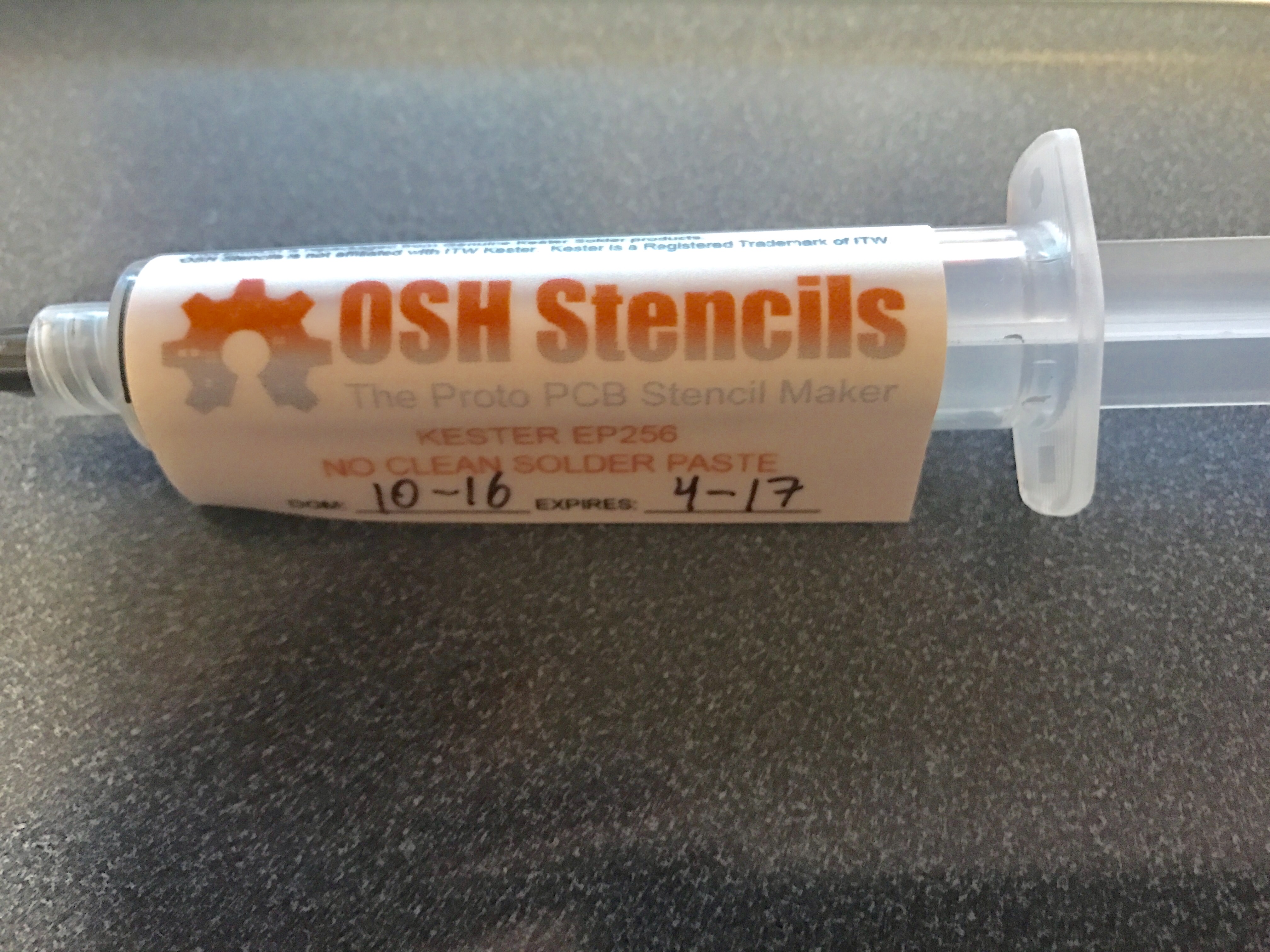
You need to have solder paste at room temperature as cold solder paste does not spread very well. I recommend that you take the solder paste out of the refrigerator at least two hours before you use it. I use Kester EP256 solder which comes in a syringe or a tub. In this case, I purchased it from OSH Stencils when I bought the original stencil. In two of the videos I watched on the internet, the person put extra solder back into the tub but obviously that cannot be done with a syringe. My experience has been that older solder paste that has been exposed to air will not reflow properly. That will make you crazy, and is the reason why I have not gone down the road of saving extra solder. I cannot emphasize enough to keep your solder cool and fresh.
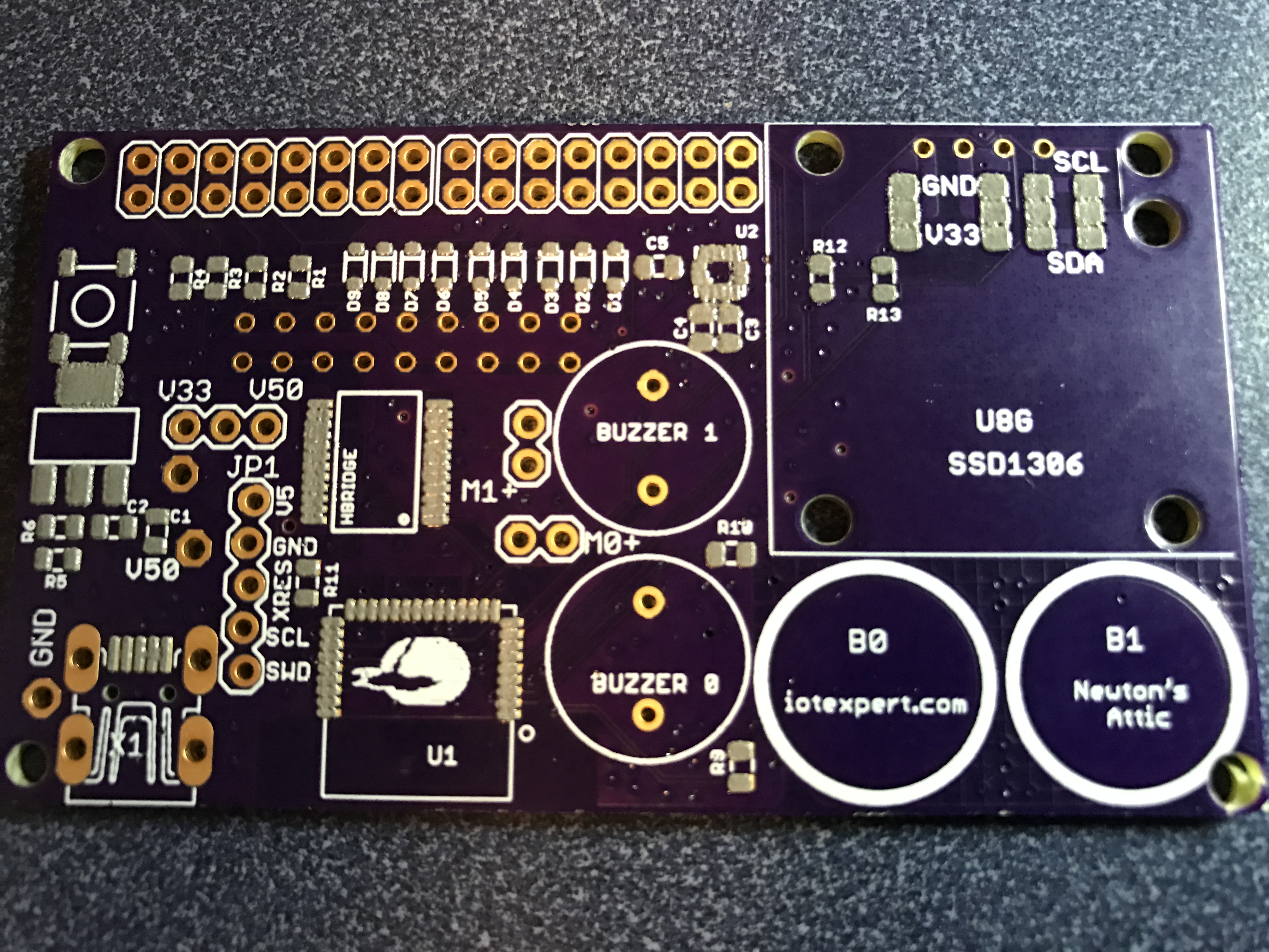
Test Fit Components onto the OSH Park /Eagle PCB
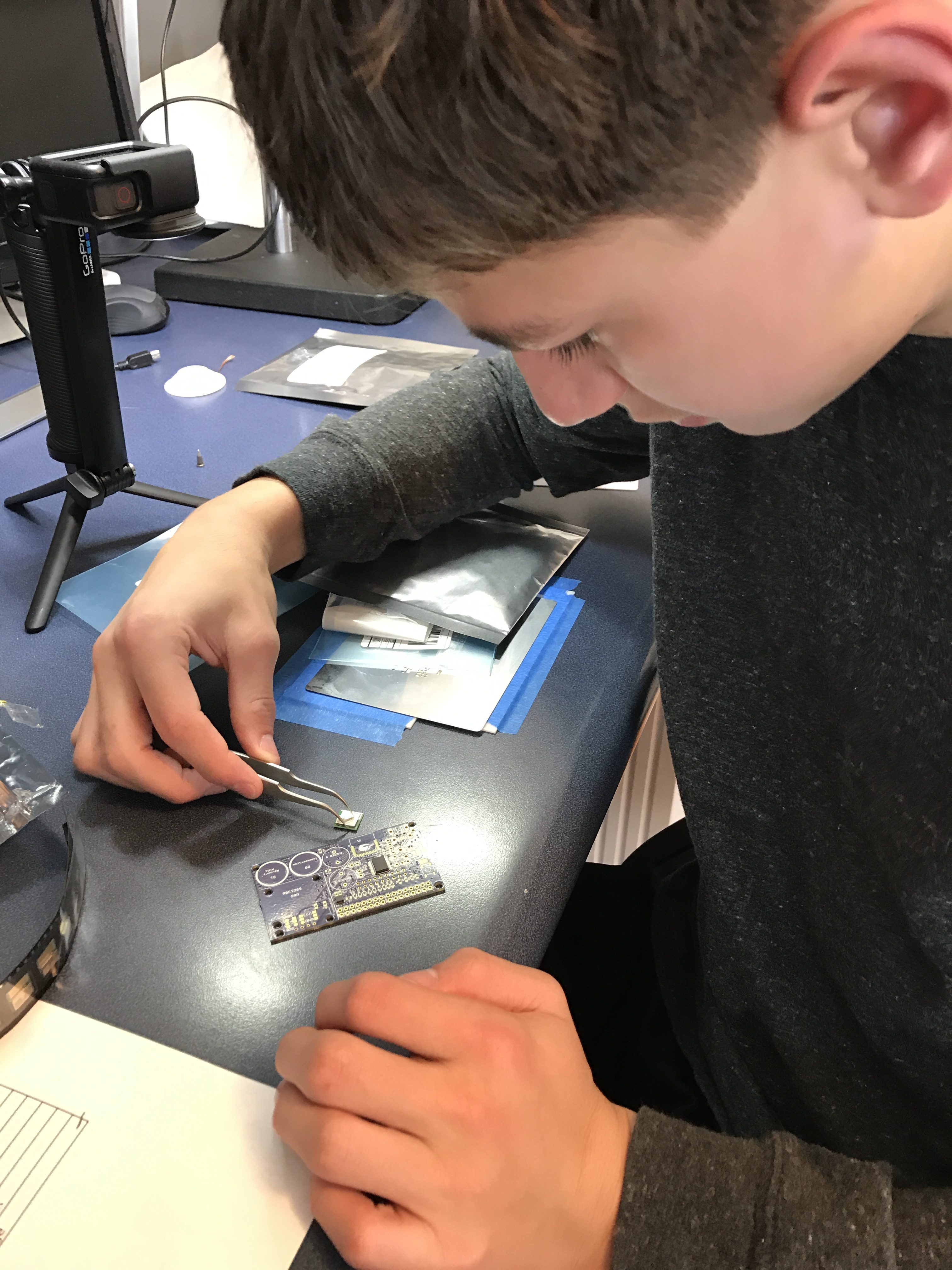
When I get a new board, the first thing that I do is make sure that the major parts align to their footprint. You don’t want to get down the road with paste on your PCB and find that you screwed up the size or placement of a component. Here is a picture of my lab assistant test fitting the PSoC.
Parts Checklist
While I am designing the PCB in Eagle I always create a BOM spreadsheet with the names of the parts, the part number, the label on PCB silkscreen, etc. I use this spreadsheet to ensure that I have all of the parts available to put on the board. It sucks to get a PCB with solder paste on it, then be missing a part that you need. Moreover, you need to move reasonably quickly once you have paste on the board (or the paste will harden) so making sure you have everything at hand is critical.

Setup all of the parts on the desk in some order
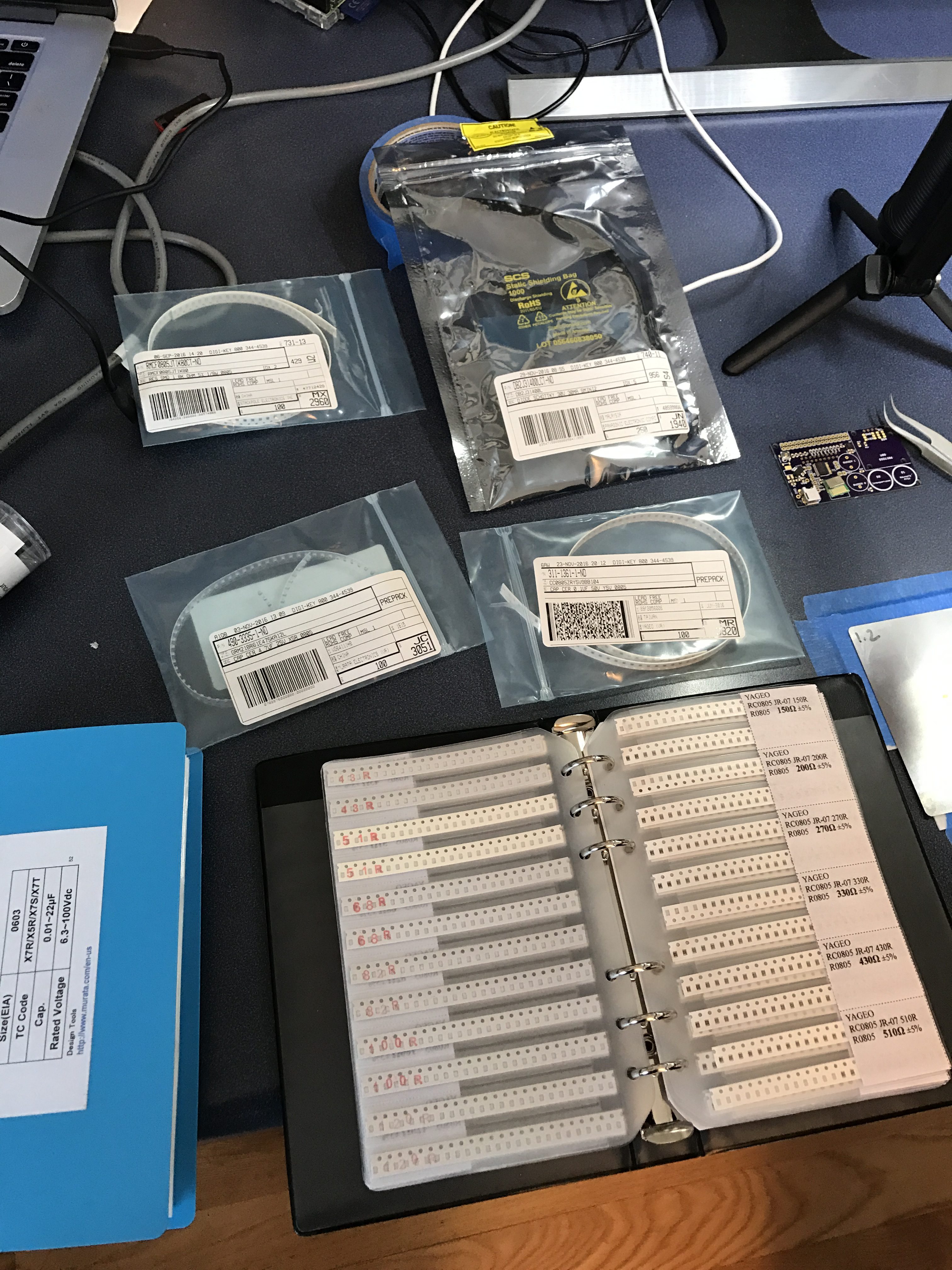
For some strange reason, it always feels stressful placing the parts onto the PCB. In order to make the process smoother, I arrange the parts on my desk in some order. In this case, all of the parts are by type i.e the resistors are all together.
Tape the PCB Brackets onto the Table
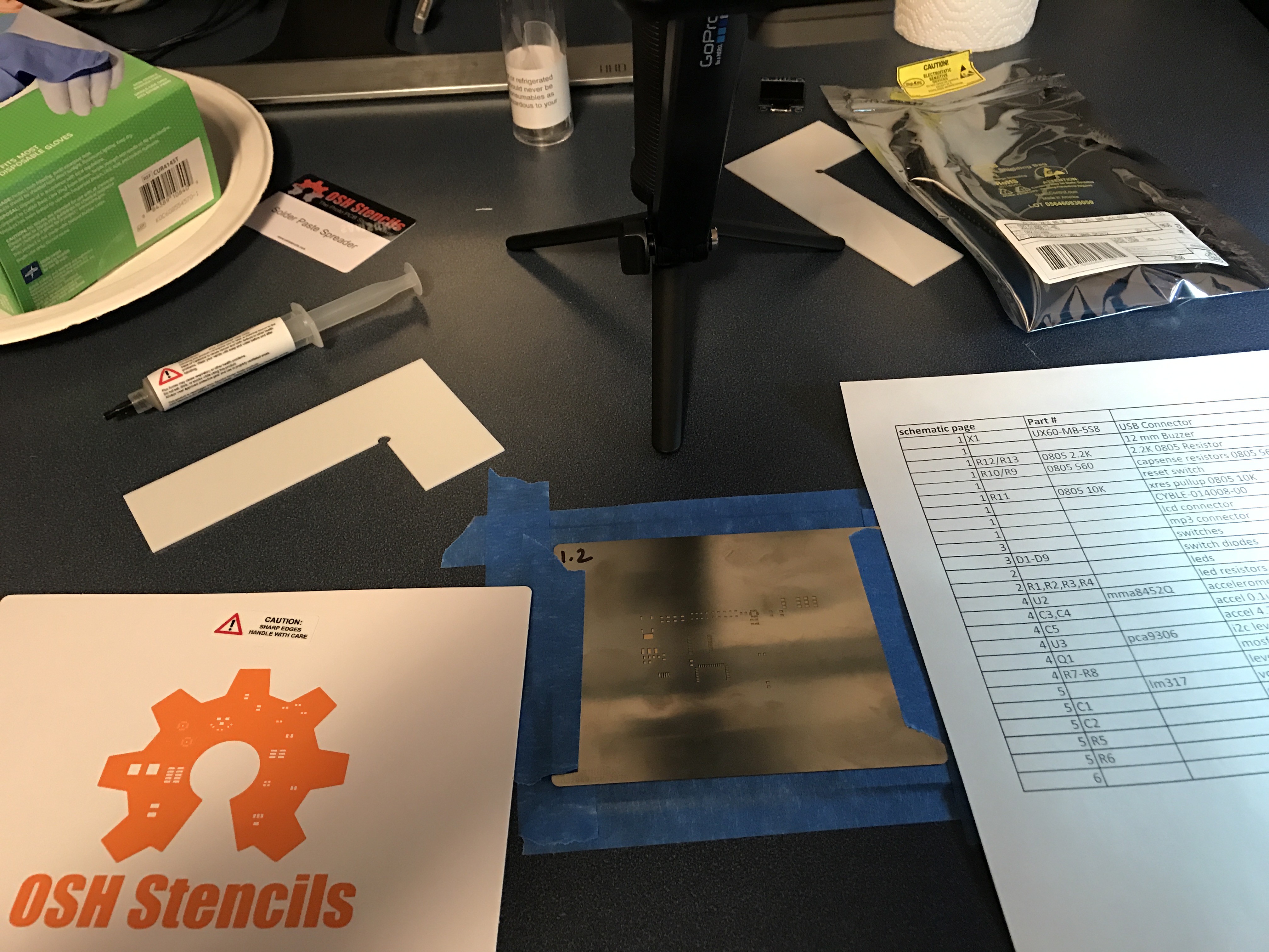
Once I have things setup, I use angled brackets (which came from oshstencils) to hold the board. I use blue painters tape from Lowes to hold it all together. The other thing that I do during this step is remove the tabs from the PCB manufacturing process and file off the rough edges. The file is just a finger nail file I bootlegged from my wife (don’t tell).

Make sure the Stencil Registers Correctly
The next step is to insure that the stencil registers properly with the board. You need to verify that the stencil is aligned in both the x-y and angle directions. It is easy to be “close” but twisted which will give you bad results. For this build I am using a metal stencil from OSH Stencils.
Screen on the PCB Solder Paste
Once every is lined up, you screen on the solder page. Here is a video of me doing it for this PCB.
When I was originally trying to figure out how to make this whole process work I found this video from SparkFun which was very useful.
Inspect the PCB Solder Paste with Microscope
Once you have the solder paste screened onto the board, you should look at it carefully. I typically use my microscope because my vision is not that great. However, this blowup picture of the board works pretty well. The only real problem in this picture is the blob of solder on U2 (the Accelerometer) which will cause problems in the reflow. It is very tough to not get too much solder on the 0.5mm pitch pads.
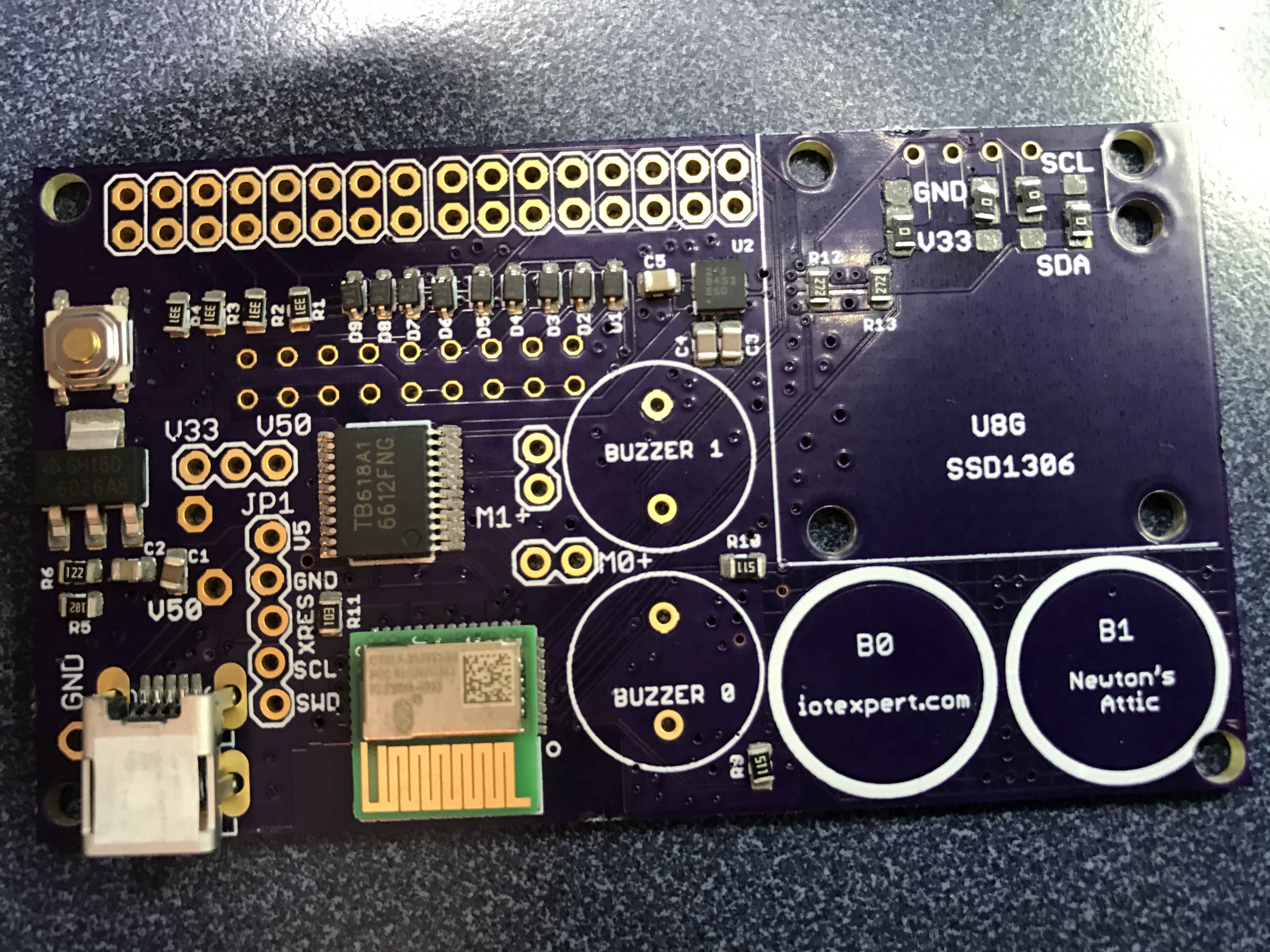
Place all of the Parts onto the PCB
I was originally planning on making a video of placing the parts onto the board. But, I need to look in the microscope while I am placing the parts on the board and I didn’t have a good way to record video. I use a pair of Hakko 7-sa non-static tweezers which I bought from Amazon. I have a bunch of different pairs of tweezers and these are by far the best. This is a picture after all of the parts are placed:
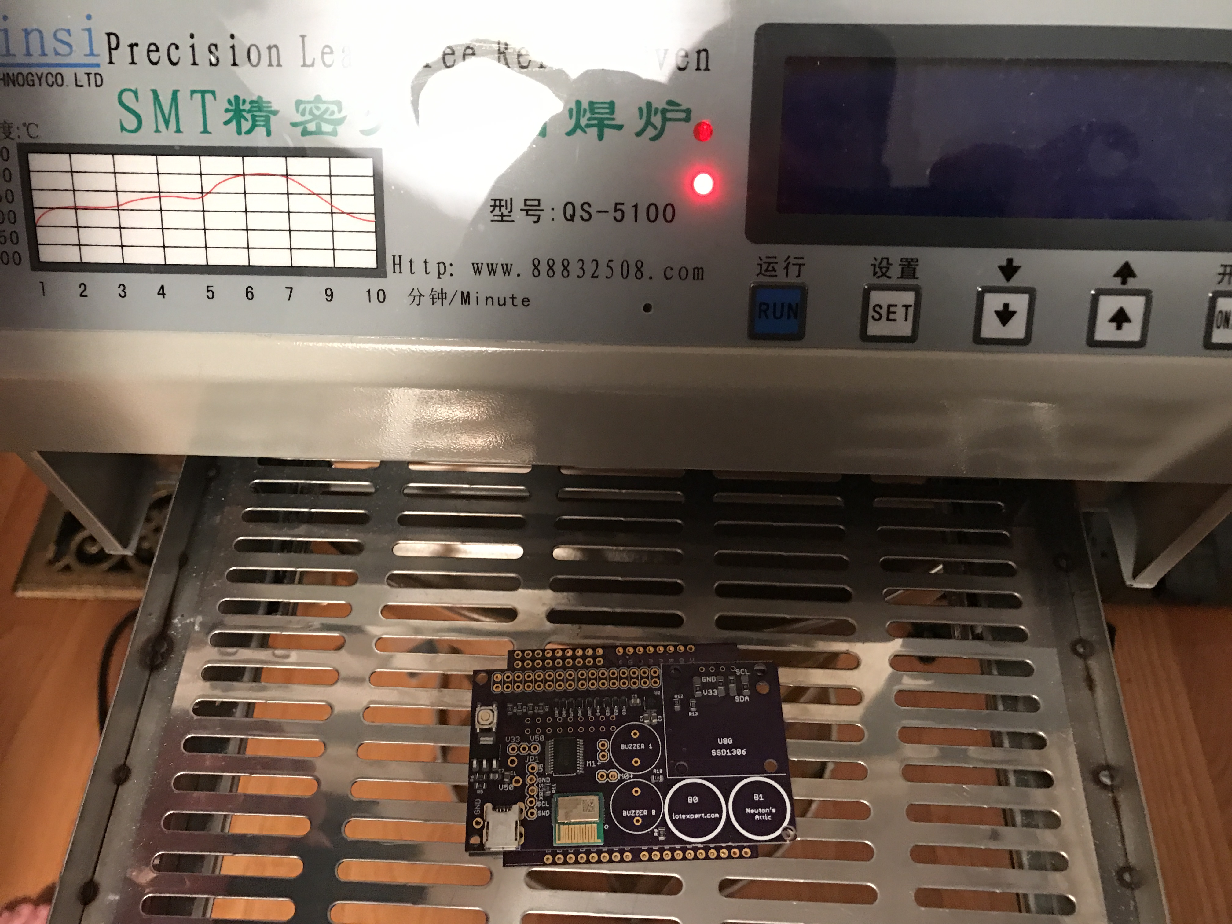
Place in Qinsi QS-5100 PCB Solder Reflow Oven
Now that you have the parts placed onto the PCB, it is time to place it in the PCB solder reflow oven. I have found that it works best to have my PCB sitting on another board in the middle of the tray (a tip that I got from Ian Lesnet of Dangerous Prototypes).
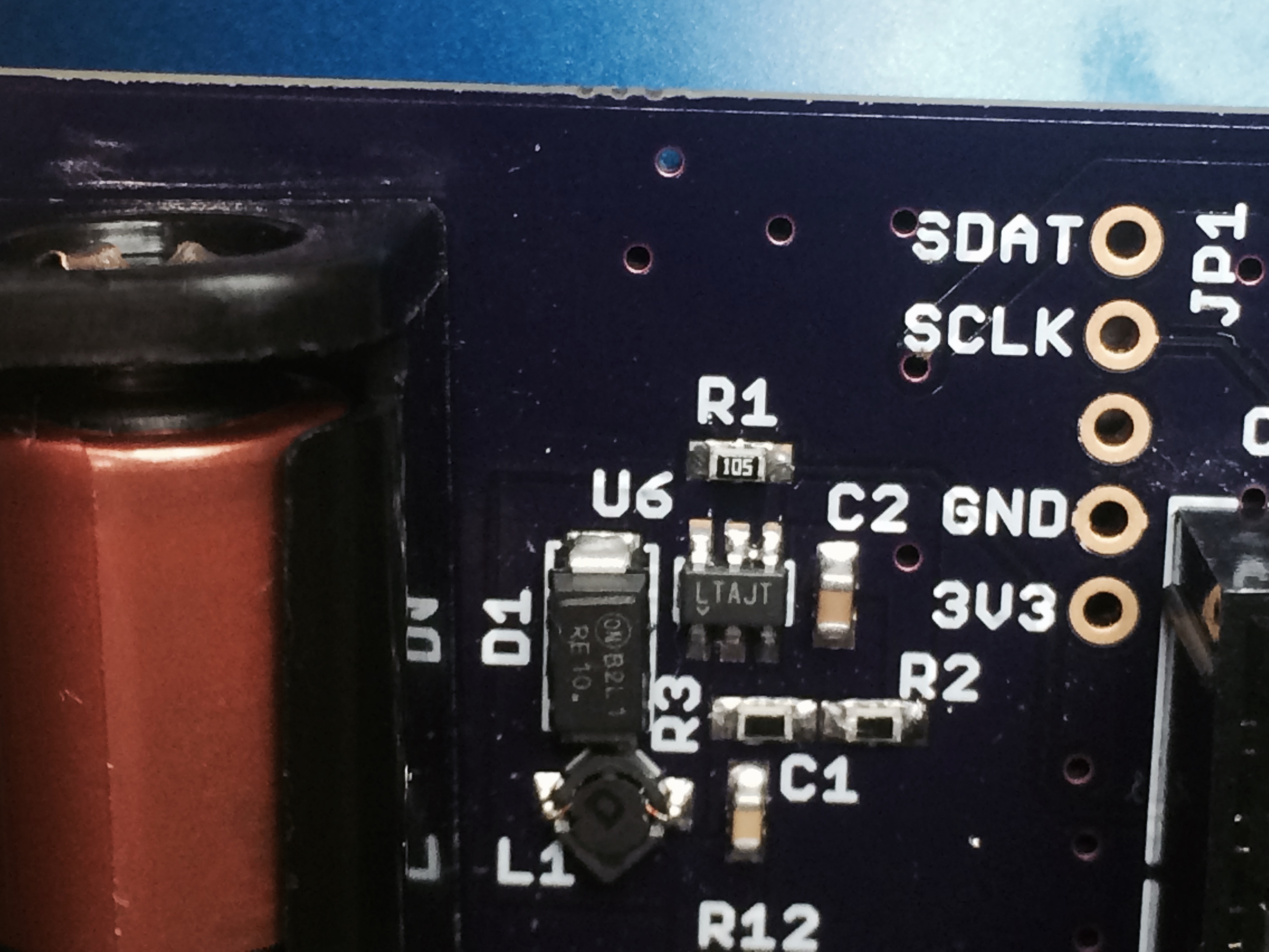
Visually Inspect the Solder and Clean up any Solder Balls
I almost always end up with 1 or 2 solder balls stuck between the pins of one of the chips. When you are running the reflow, solder that isn’t attached to anything will ball up because of the surface tension. Murphy’s law says that the solder balls will not end up anyplace good, and will for sure short some pins together. You should look carefully for these balls or bridges and clean them up with your soldering iron. This is a picture of a solder ball from another project. You can see it between the right two pins on U6 (the chip labeled LTAJT). The easy way to fix the ball is to squirt a little bit of flux on it, then touch it with your soldering iron. That will melt the ball onto the pins next to it.
Solder the Programmer Connector into the PCB
The (almost) last step is to solder on the header for the Miniprog-3. Then let it rip with a blank program program.

Cleanup the Disaster Area
Once all of that is done, my office is a complete and total disaster area. Yes, I use gloves when I work with solder and you should as well.

In the next post I will take you through the steps I followed to test the Pinball PCB.
You can find all of the source code and files at the IOTEXPERT site on github.
| Index | Description |
|---|---|
| Pinball: Newton's Attic Pinball | An introduction to the project and the goals |
| Pinball: Lotsa Blinking LEDs | Everyone needs a bunch of LEDs on their Pinball Machine |
| Pinball: Matrix LEDs (Part 1) | Saving PSoC pins by using a matrix scheme |
| Pinball: Matrix LEDs (Part 2) | Solving some problems with the matrix |
| Pinball: Matrix LEDs Component | How to turn the Matrix LED into a component |
| Pinball: A Switch Matrix | Implementing a bunch of switches |
| Pinball: Switch Matrix Component (Part 1) | The switch matrix component implementation |
| Pinball: Switch Matrix Component (Part 2) | The firmware for matrix component |
| Pinball: Switch Matrix Component (Part 3) | Test firmware for the matrix component |
| Pinball: The Music Player (Part 1) | The schematic and symbol for a Music Player component |
| Pinball: The Music Player (Part 2) | The Public API for the Music Player component |
| Pinball: The Music Player (Part 3) | The firmware to make the sweet sweet music |
| Pinball: The Music Player (Part 4) | The test program for the music player |
| Pinball: The Motors + HBridge | Using an Bridge to control DC Motors |
| Pinball: The Eagle Schematic | All of the circuits into an Eagle schematic |
| Pinball: The Printed Circuit Board 1.0 | The first Eagle PCB layout of the printed circuit board |
| Pinball: The PCB Version 1.0 Fail | Problems with the first version of the Eagle PCB layout |
| Pinball: PCB Layout 1.2 Updates using Eagle | Fixing the errors on the first two versions of the Eagle PCB |
| Pinball: Assemble and Reflow the 1.2 PCB | Assembling the Eagle PCB |
| Pinball: Testing the Eagle PCB | Firmware to test the newly built Pinball printed circuit board |
| Pinball: Debugging the Motor Driver | Fixing the motor driver PSoC project |
| Pinball: Hot-Air Reworking the Accelerometer Solder | Using a Hot-Air Rework tool to reflow a QFN |
| Pinball: Debugging the LM317 Power Supply- A Tale of Getting Lucky | Debugging the LM317/LM117 power supply |
No comment yet, add your voice below!