IoT Design with Cypress PSoC® 6 MCUs and Wi-Fi/Bluetooth using Arm® Mbed™
You can “mbed import https://github.com/iotexpert/mouser-mbed-09.git“ to make a copy of the project in your workspace.
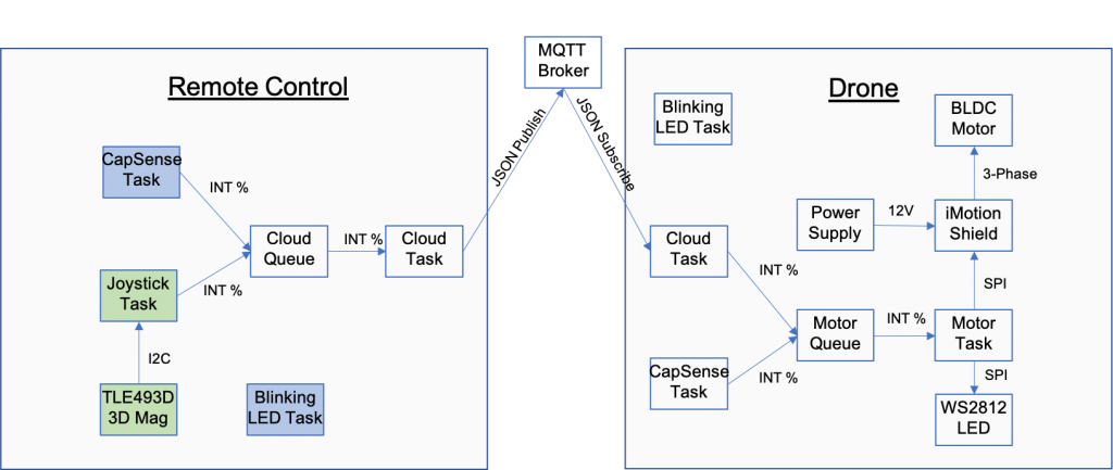
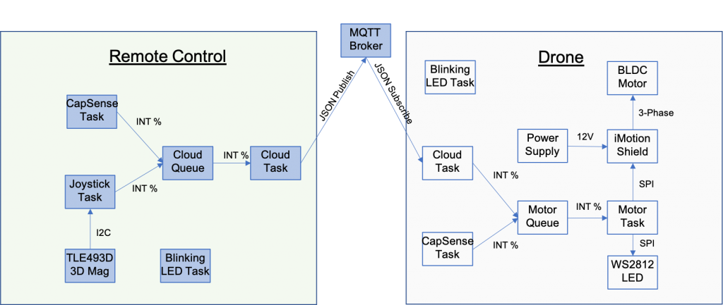
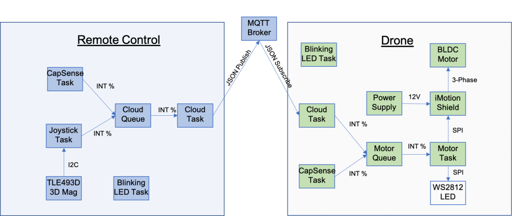
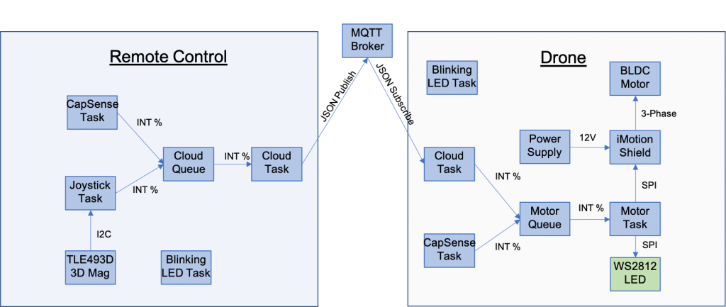
The final architecture of the thermostat looks like this.

Summary
In this lesson we will add an output capability to our project. But what output device? I am going old school with a serial terminal using VT100 graphics commands.
Here is the update to the architecture. Notice the new green boxes.
- A new thread (called Display Thread)
- The Serial terminal
- An RTC (the one built into the PSoC 6)
- An RTOS Queue called “Display Command Queue”
- A function called displaySendUpdateTime (to tell the display to show the time)
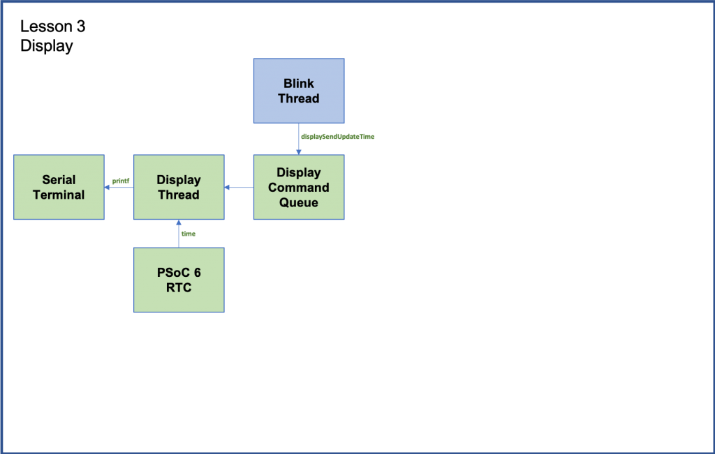
The way this will work is a new thread called “displayThread” will be created. I will have an RTOS queue associated with it. Tasks that want to display something will push a message into the queue. The display thread will wait around until some other task pushes a message into the queue. When another task pushes a message, the displayThread will process the message and “do the needful”.
To implement this I will:
- Import from GitHub lesson02
- Discuss VT100 Commands
- Create & code displayThread.h
- Create & code displayThread.cpp
- Create & code mbed_app.json
- Update blinkThread.cpp
- Update main.cpp
- Build, Program and Test
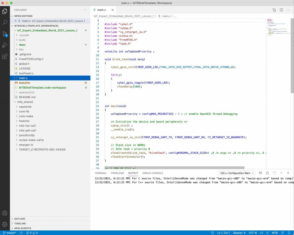
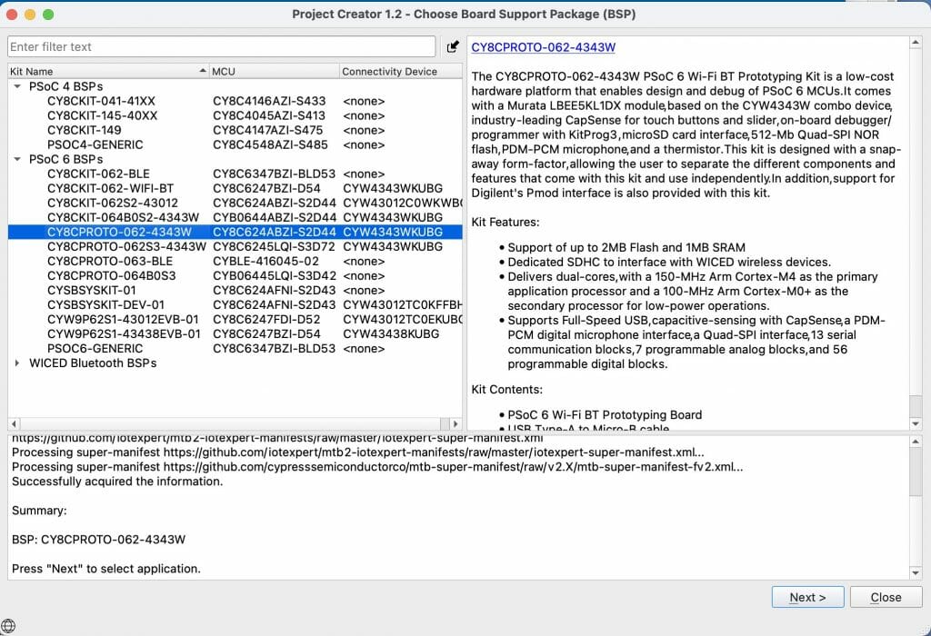
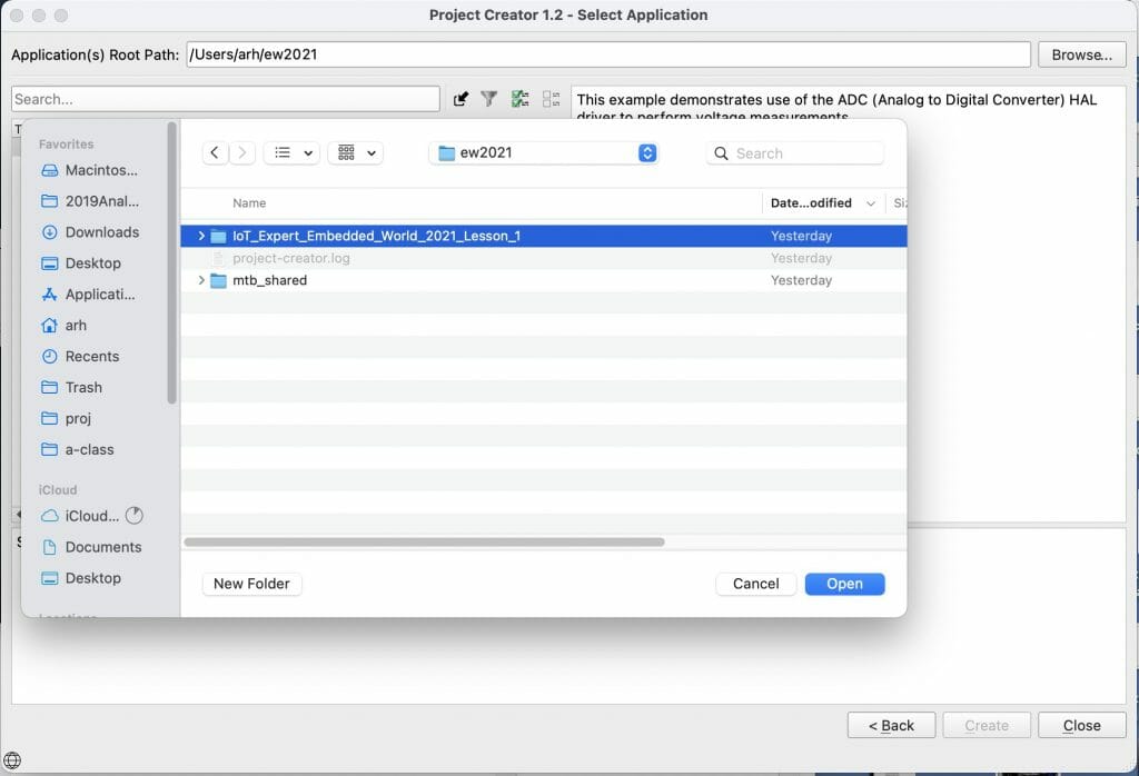
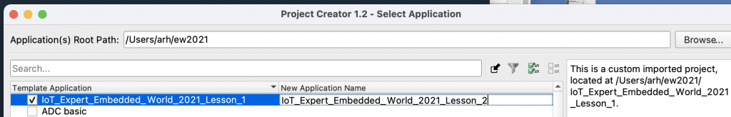
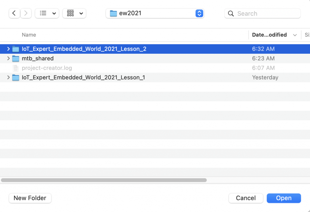
Import from GitHub Lesson 02
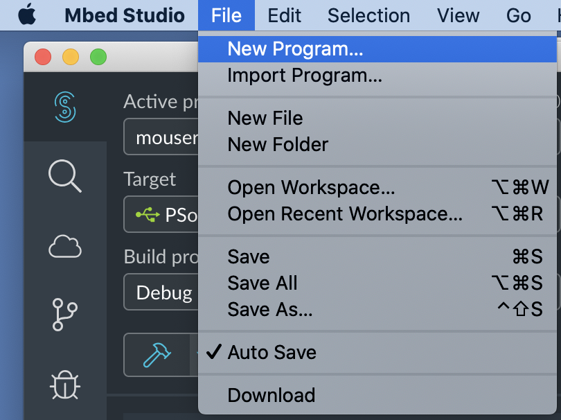
Mbed Studio can start a new project by “importing” an old project and giving it a new name. This is a super convenient way for me to build each project for this class on the base of the previous one. To make this easier for you I save each of these lesson projects on GitHub so you can start from there.
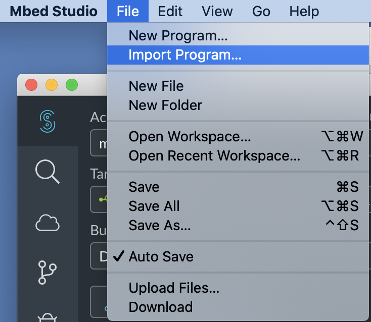
In Mbed Studio use “File->Import Program…”
Give it the path to my github site for the project you want to start from:
https://github.com/iotexpert/mouser-mbed-02.git
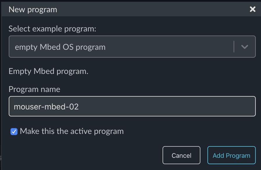
And then give it the new name you want for the new project – in this case mouser-mbed-03
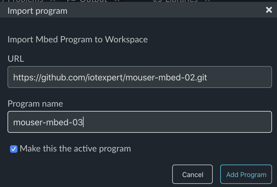
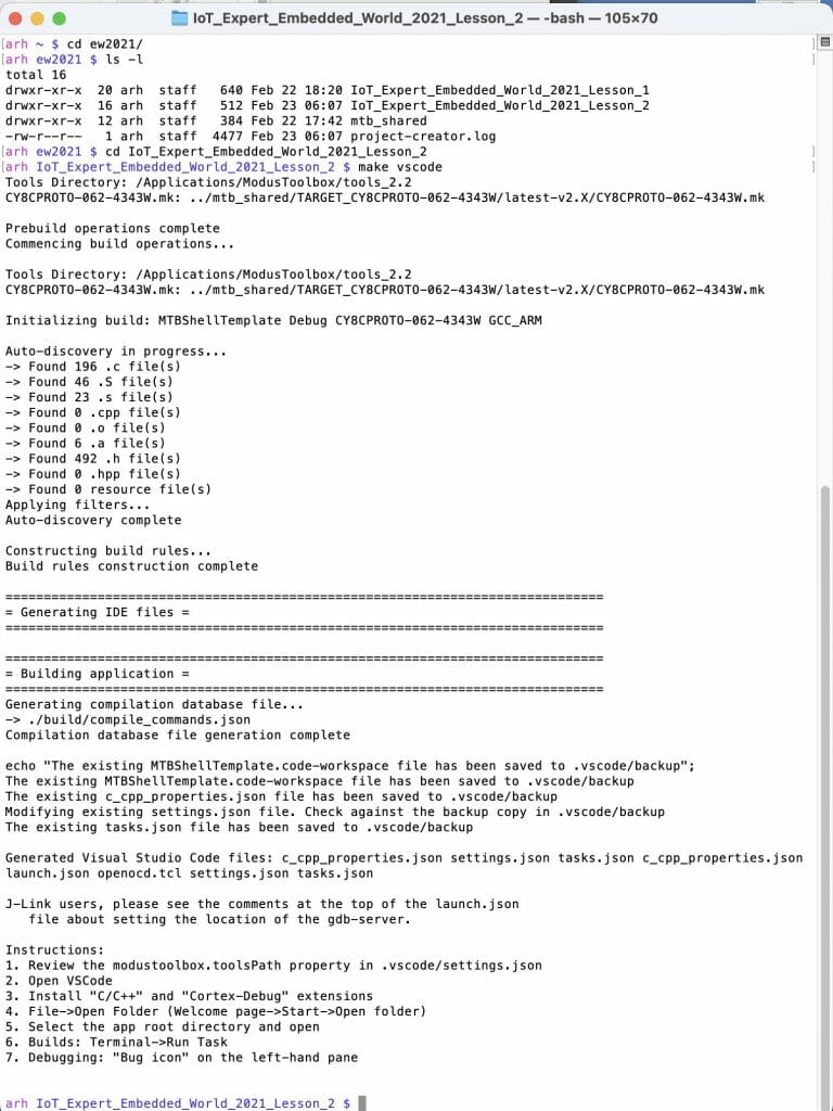
After clicking “Add program” you should have a new program called “mouser-mbed-03” and it should be set as the active program.
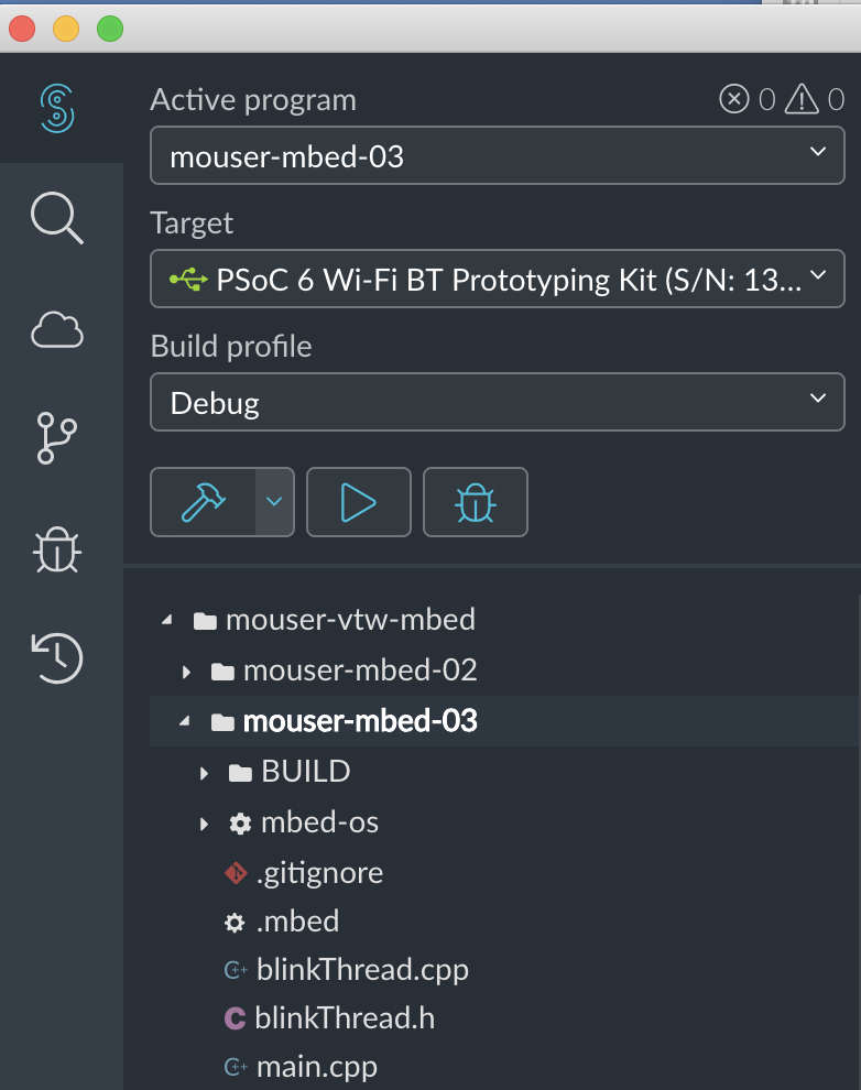
At this point you could press the play button and get exactly the same behavior as the previous lesson 02.
VT100 Commands
Back in the dark ages when I started programming, most work was done on a “main frame” of some kind or the other. The two that I used were the PDP-11 and the Prime. To access these systems you typically used a “Dumb Terminal” attached to the mainframe via a long serial cable. One of the most used terminals was the VT100 made by Digital Equipment Corporation (DEC).

These terminals could output a fixed width font in about 80 columns and 24 rows. Basically, the mainframe sent ASCII characters and the terminal would display them.
An interesting feature that was put into these terminals was the ability to take commands and move the cursor around to screen, or clear it, or draw a line or ….
What does that have to do with today? Simple, the VT100 command set is still used by almost all serial programs on your PC (Putty, etc). And I am going to use these commands to create a graphical user interface for the thermostat that looks like this:
- Line 1 will be the current temperature
- Line 2 will be the setPoint of the thermostat
- Line 3 will be the time
- Line 4 will be the status of the system (Heat, Cool or Off)
To use the VT100 commands you just use printf to send them to the serial terminal. The commands I will use are:
| Command |
ESC Sequence |
printf |
|---|
| Home |
ESC [ H |
printf("\033[H"); |
| Clear Screen |
ESC [ J |
printf("\033[2J"); |
| Turn Cursor Off |
ESC [ ? 25l |
printf("\033[?25l"); |
| Goto column & row |
ESC [ column ; row H |
printf("\033[%d;%dH%s",y,x,buffer); |
Add displayThread.h
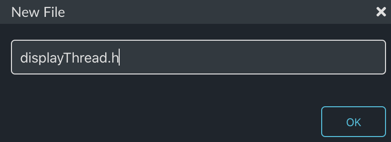
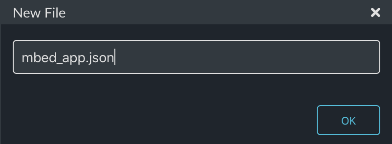
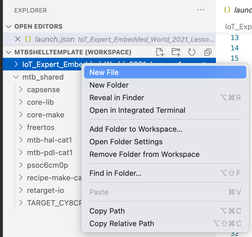
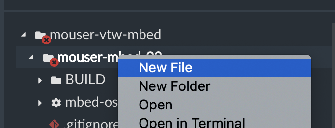
As in lesson 02 I will create a new thread. This time the header file will be called “displayThread.h” Right click and select “New File”
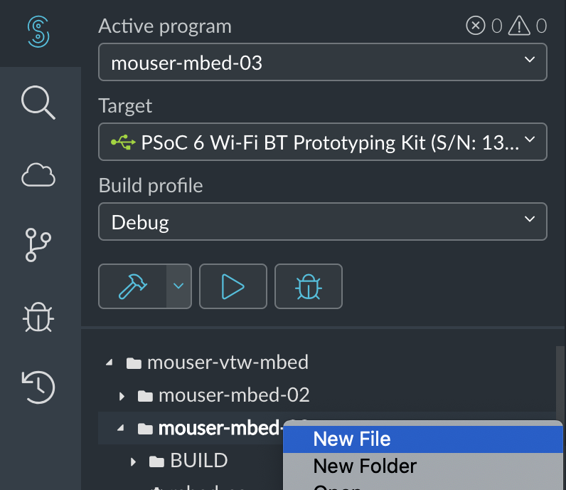
Give it the name “displayThread.h”
This file will:
- Guard against multiple include
- Provide the function prototype of the thread
- Provide four functions to tell the displayThread to write onto the four different lines of the GUI
#ifndef DISPLAY_THREAD_H
#define DISPLAY_THREAD_H

void displayThread();


void displaySendUpdateTemp(float temperature);
void displaySendUpdateTime();
void displaySendUpdateSetPoint(float setPoint);
void displaySendUpdateMode(float mode);

#endif
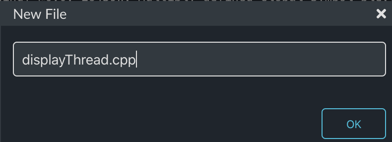
Add displayThread.cpp
From now on I will just show the file creation. In this case “displayThread.cpp”
The first part of the file is to specify the queue. To do this I create a new type called msg_t which will be inserted into the queue (actually a pointer to the msg_t). The message structure will have two members the “command_t” and a generic floating point variable called “value”.
The Queue and Memory pool will only be accessible inside of this file. The queue will hold up to 16 “msg_t”. The MemoryPool is just an easy way to do memory allocation.
#include "mbed.h"
#include "displayThread.h"

typedef enum {
    CMD_temperature,
    CMD_setPoint,
    CMD_time,
    CMD_mode,
} command_t;


typedef struct {
    command_t cmd;
    float    value;
} msg_t;


static Queue<msg_t, 16> queue;
static MemoryPool<msg_t, 16> mpool;
In order to insert msg_t into the queue I create one function per msg_t that:
- allocates a new message
- sets the command
- sets the value
- puts the message in the queue
Notice if something goes wrong, I just ignore the problem. In a real system you would probably want to do something else.
These four functions will actually run inside of the thread that calls them, but they will insert messages into the queue that the displayThread is processing. This queue mechanism is a safe way for processes to talk to each other.
// Function called by other threads to queue a temperature change onto the display
void displaySendUpdateTemp(float temperature)
{
    msg_t *message = mpool.alloc();
    if(message)
    {
        message->cmd = CMD_temperature;
        message->value = temperature;
        queue.put(message);
    }
}

// Function called by other threads to queue display to update time
void displaySendUpdateTime()
{
    msg_t *message = mpool.alloc();
    if(message)
    {
        message->cmd = CMD_time;
        message->value = 0;
        queue.put(message);
    }
}

// Function called by other threads to queue a setPoint change onto the display
void displaySendUpdateSetPoint(float setPoint)
{
    msg_t *message = mpool.alloc();
    if(message)
    {
        message->cmd = CMD_setPoint;
        message->value = setPoint;
        queue.put(message);
    }
}

// Function called by other threads to queue a setPoint change onto the display
void displaySendUpdateMode(float mode)
{
    msg_t *message = mpool.alloc();
    if(message)
    {
        message->cmd = CMD_mode;
        message->value = mode;
        queue.put(message);
    }
}
The function displayAtXY creates a string with the VT100 Goto command plus the string that was send.
static void displayAtXY(int x, int y,char *buffer)
{
    // row column
    printf("\033[%d;%dH%s",y,x,buffer);
    fflush(stdout);
}
The actual display thread:
- Clears the screen and turns the cursor off
- Goes into an infinite loop waiting for messages to be put into the queue
- When a new message comes in, look at the command
- sprintf to create the display message
- print it using the displayAtXY function
void displayThread()
{
    char buffer[128];

    printf("\033[2J\033[H"); // Clear Screen and go Home
    printf("\033[?25l"); // Turn the cursor off
    fflush(stdout);

    while(1)
    {
        osEvent evt = queue.get();
        if (evt.status == osEventMessage) {
            msg_t *message = (msg_t*)evt.value.p;
            switch(message->cmd)
            {
                case CMD_temperature:
                    sprintf(buffer,"Temperature = %2.1fF",message->value);
                    displayAtXY(1, 1, buffer);
                break;
                case CMD_setPoint:
                    sprintf(buffer,"Set Point = %2.1fF",message->value);
                    displayAtXY(1, 2, buffer);
                break;
                case CMD_time:
                    time_t rawtime;
                    struct tm * timeinfo;
                    time (&rawtime);
                    rawtime = rawtime - (5*60*60); // UTC - 4hours ... serious hack which only works in winter
                    timeinfo = localtime (&rawtime);
                    strftime (buffer,sizeof(buffer),"%r",timeinfo);
                    displayAtXY(1,3, buffer);
                break;
                case CMD_mode:
                    if(message->value == 0.0)
                        sprintf(buffer,"Mode = Off ");
                    else if (message->value < 0.0)
                        sprintf(buffer,"Mode = Heat");
                    else
                        sprintf(buffer,"Mode = Cool");
                    displayAtXY(1, 4, buffer);
                break;

            }
            mpool.free(message);

        }
    }
}
Here is the whole file displayThread.cpp (to make a copy/paste easier):
#include "mbed.h"
#include "displayThread.h"

typedef enum {
    CMD_temperature,
    CMD_setPoint,
    CMD_time,
    CMD_mode,
} command_t;


typedef struct {
    command_t cmd;
    float    value;
} msg_t;


static Queue<msg_t, 32> queue;
static MemoryPool<msg_t, 16> mpool;

// Function called by other threads to queue a temperature change onto the display
void displaySendUpdateTemp(float temperature)
{
    msg_t *message = mpool.alloc();
    if(message)
    {
        message->cmd = CMD_temperature;
        message->value = temperature;
        queue.put(message);
    }
}

// Function called by other threads to queue display to update time
void displaySendUpdateTime()
{
    msg_t *message = mpool.alloc();
    if(message)
    {
        message->cmd = CMD_time;
        message->value = 0;
        queue.put(message);
    }
}

// Function called by other threads to queue a setPoint change onto the display
void displaySendUpdateSetPoint(float setPoint)
{
    msg_t *message = mpool.alloc();
    if(message)
    {
        message->cmd = CMD_setPoint;
        message->value = setPoint;
        queue.put(message);
    }
}

// Function called by other threads to queue a setPoint change onto the display
void displaySendUpdateMode(float mode)
{
    msg_t *message = mpool.alloc();
    if(message)
    {
        message->cmd = CMD_mode;
        message->value = mode;
        queue.put(message);
    }
}

static void displayAtXY(int x, int y,char *buffer)
{
    // row column
    printf("\033[%d;%dH%s",y,x,buffer);
    fflush(stdout);
}


///////////////////////////////////////////////////////////////////////////////////////////////////////////

void displayThread()
{
    char buffer[128];

    printf("\033[2J\033[H"); // Clear Screen and go Home
    printf("\033[?25l"); // Turn the cursor off
    fflush(stdout);

    while(1)
    {
        osEvent evt = queue.get();
        if (evt.status == osEventMessage) {
            msg_t *message = (msg_t*)evt.value.p;
            switch(message->cmd)
            {
                case CMD_temperature:
                    sprintf(buffer,"Temperature = %2.1fF",message->value);
                    displayAtXY(1, 1, buffer);
                break;
                case CMD_setPoint:
                    sprintf(buffer,"Set Point = %2.1fF",message->value);
                    displayAtXY(1, 2, buffer);
                break;
                case CMD_time:
                    time_t rawtime;
                    struct tm * timeinfo;
                    time (&rawtime);
                    rawtime = rawtime - (5*60*60); // UTC - 4hours ... serious hack which only works in winter
                    timeinfo = localtime (&rawtime);
                    strftime (buffer,sizeof(buffer),"%r",timeinfo);
                    displayAtXY(1,3, buffer);
                break;
                case CMD_mode:
                    if(message->value == 0.0)
                        sprintf(buffer,"Mode = Off ");
                    else if (message->value < 0.0)
                        sprintf(buffer,"Mode = Heat");
                    else
                        sprintf(buffer,"Mode = Cool");
                    displayAtXY(1, 4, buffer);
                break;

            }
            mpool.free(message);

        }
    }
}
Create mbed_app.json
By default the serial terminal on Mbed OS is 9600 baud or approximately the same speed as back in VT100 days. Fortunately you can change that by setting up a global configuration. To do this you need to create a file called “mbed_app.json”.
In that file, I tell the system that I want 115200 baud for all targets.
{
    "target_overrides": {
        "*": {
            "platform.stdio-baud-rate": 115200
        }
    }
}
Update blinkThread.cpp
In order to test the new displayThread, I will fix up the blinkThread to temporarily send the four messages.
#include "mbed.h"
#include "blinkThread.h"
#include "displayThread.h"

static DigitalOut led1(LED1);

void blinkThread()
{

    while (true)
    {
        led1 = !led1;
        displaySendUpdateTime();
        displaySendUpdateTemp(69.2);
        displaySendUpdateSetPoint(23.5);
        displaySendUpdateMode(-1.0);
        ThisThread::sleep_for(500);
    }
}
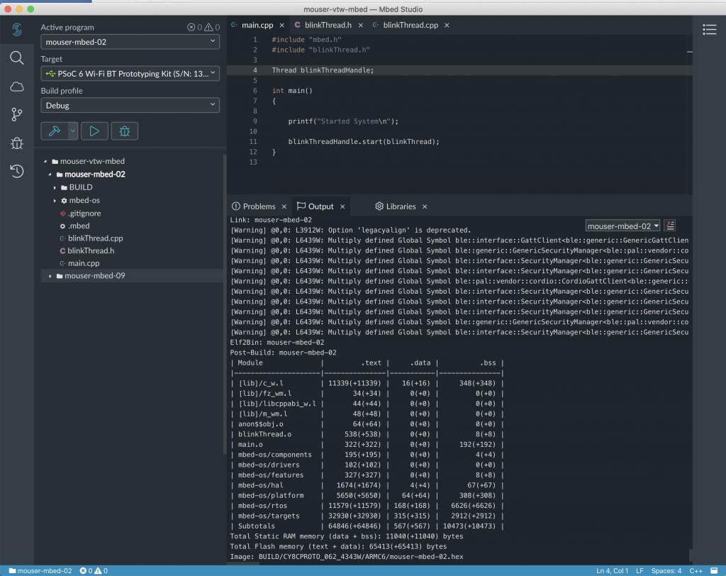
Update main.cpp
The last step is to update main to start the new displayThread.
#include "mbed.h"
#include "blinkThread.h"
#include "displayThread.h"

Thread blinkThreadHandle;
Thread displayThreadHandle;

int main()
{

    printf("Started System\n");

    blinkThreadHandle.start(blinkThread);
    displayThreadHandle.start(displayThread);

}
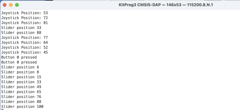
Build, Program and Test
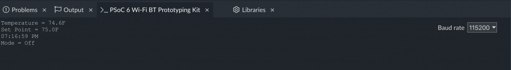
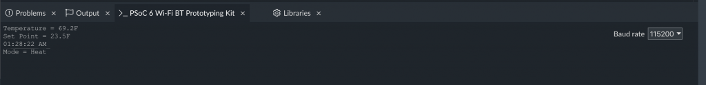
Now press the play button.
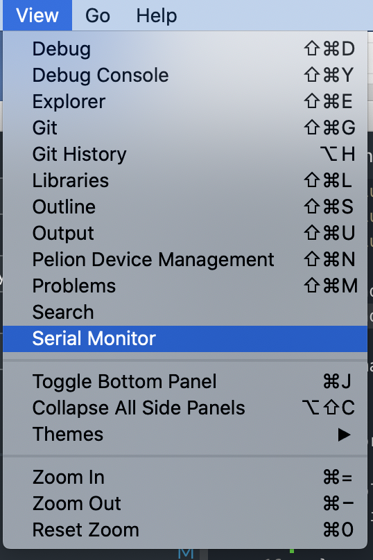
One nice thing in Mbed Studio is a built-in serial port viewer. You can use it by clicking “View -> Serial Monitor”
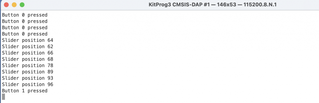
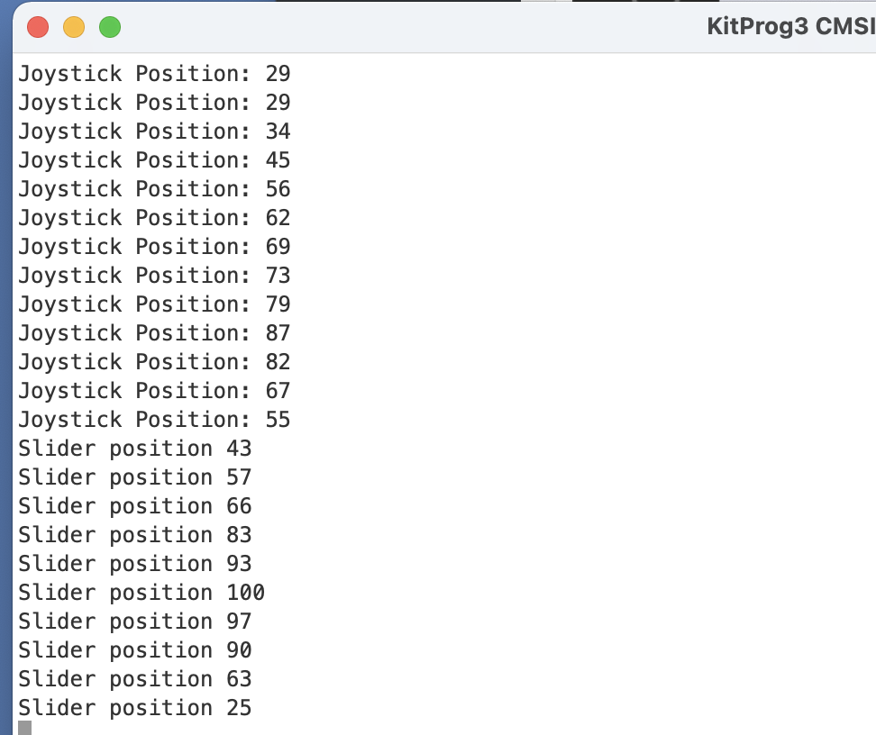
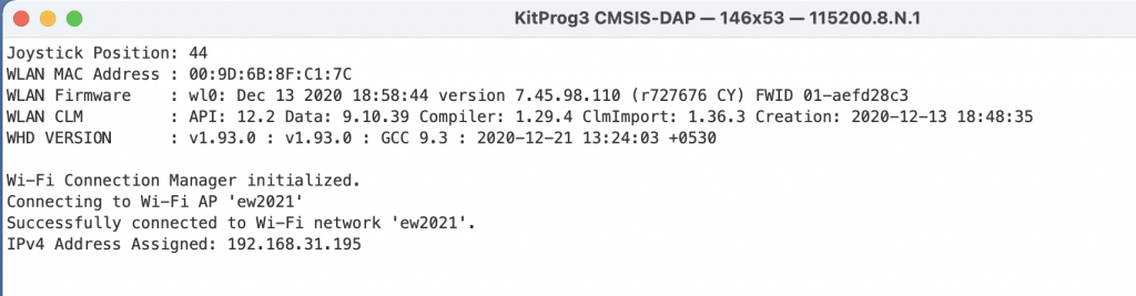
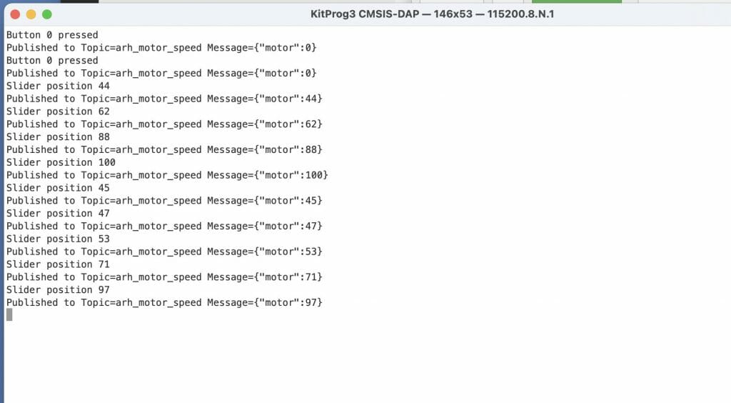
Change the baud rate to 115200 and you should see something like this:


