Summary
In the previous articles I took you through the first part of the PSoC4 Boot Sequence, then I showed you how the exception vectors got into the flash, lastly I showed you the Start_C() function and how it initializes your program variables. After that your main() should start, right? But wait, when does the PSoC get initialized? Is it magic? This article answers that question and explains the evil linker trickery __attribute_((constructor(101)) that is used to call the “initialize_psoc()” function.
For many many reasons, one of my heroes is Brian Kernighan. He just gets “it” and even better, he can explain “it” beautifully. One of my favorite Kernighan quotes is “Everyone knows that debugging is twice as hard as writing a program in the first place. So if you’re as clever as you can be when you write it, how will you ever debug it?” Our business is hard, really hard and there is absolutely no call for doing things that make it harder. Don’t be deluded, obfuscation is not elegance.
Start_c()
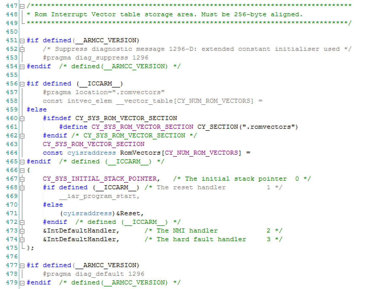
As discussed previously, the Reset() function just calls Start_C() whose role in life is to get the C program initialized (the previous article). Then it calls the function “__libc_init_array” (line 346) and finally it calls main (line 347). The first time I saw this I thought, wow that is simple. Then I started wondering, how and when does PSoC become PSoC? When I look around in the Cm0Start.c file I see a function called “initialize_psoc” (which I will talk about in the next article). But, there does not appear to be a call to “initialize_psoc()”. Did I miss it? Is it even run?
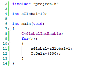
void Start_c(void)
{
#ifdef CY_BOOT_START_C_CALLBACK
CyBoot_Start_c_Callback();
#else
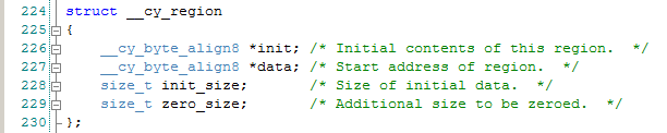
unsigned regions = __cy_region_num;
const struct __cy_region *rptr = __cy_regions;
/* Initialize memory */
for (regions = __cy_region_num; regions != 0u; regions--)
{
uint32 *src = (uint32 *)rptr->init;
uint32 *dst = (uint32 *)rptr->data;
unsigned limit = rptr->init_size;
unsigned count;
for (count = 0u; count != limit; count += sizeof (uint32))
{
*dst = *src;
dst++;
src++;
}
limit = rptr->zero_size;
for (count = 0u; count != limit; count += sizeof (uint32))
{
*dst = 0u;
dst++;
}
rptr++;
}
/* Invoke static objects constructors */
__libc_init_array();
(void) main();
while (1)
{
/* If main returns, make sure we don't return. */
}
#endif /* CY_BOOT_START_C_CALLBACK */
}
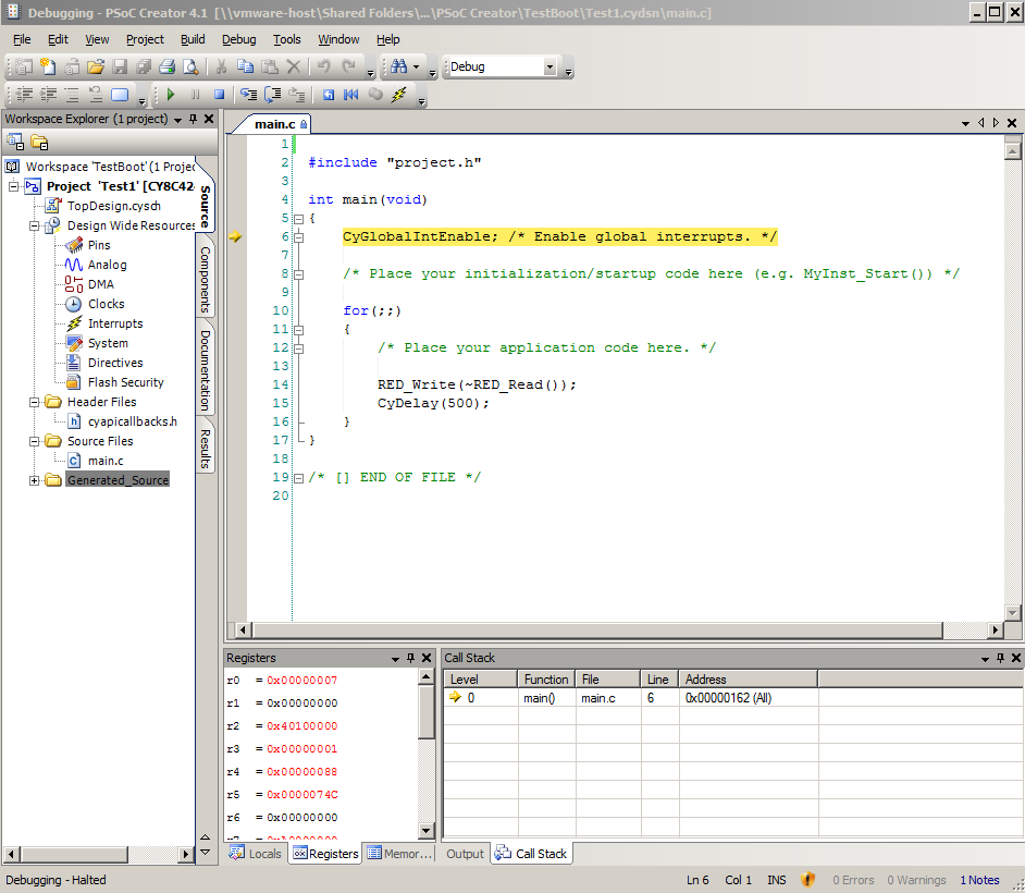
Debugging to initialize_psoc()
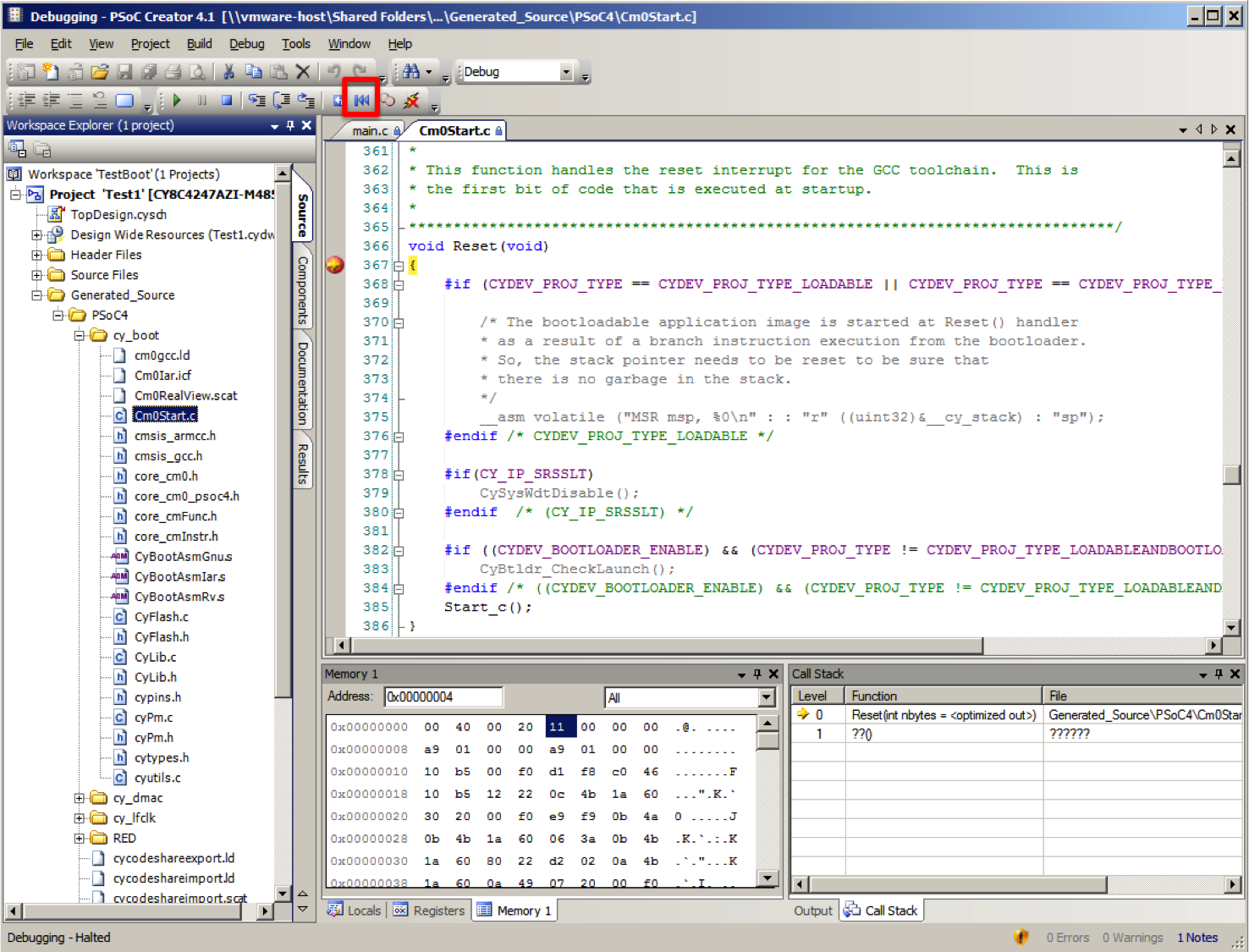
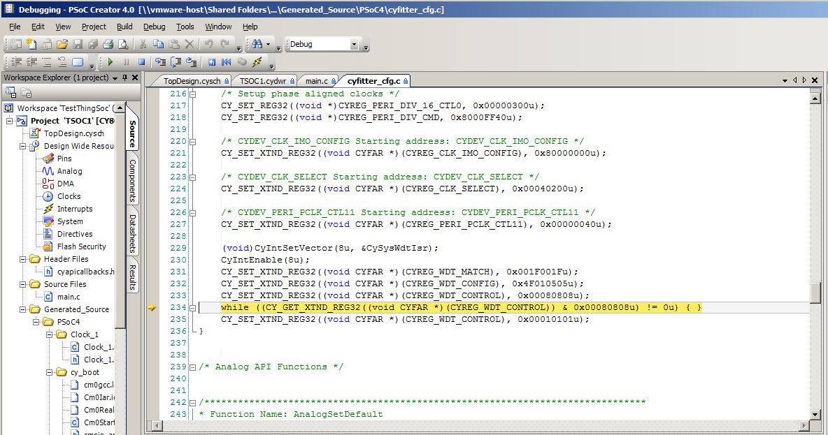
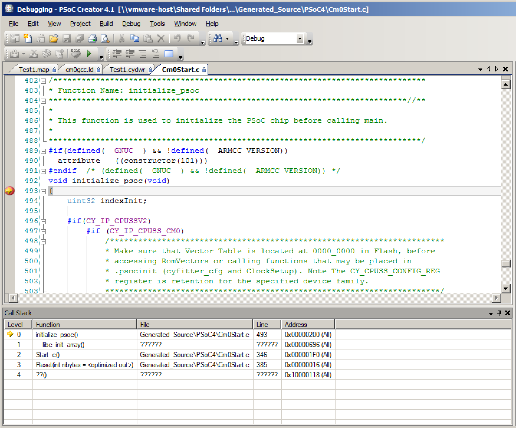
To answer the question, “where is initialize_psoc()” called, I put a breakpoint at that function. When I run the debugger, you can see that it stops at the right place, and you can see in the call stack that the function is called by the function “__libc_init_array()”. This is the point where things started to get really difficult in my life.
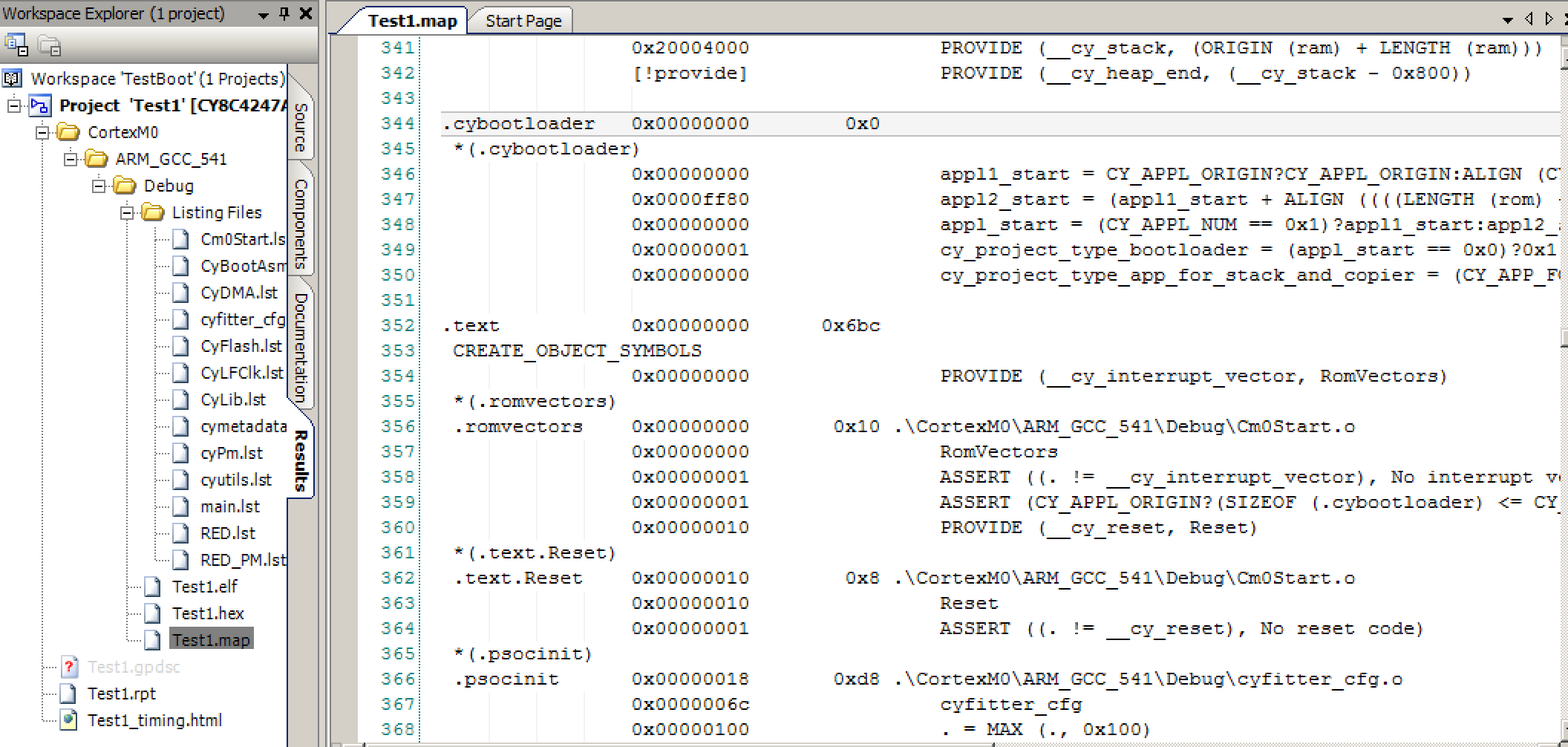
__libc_init_array()
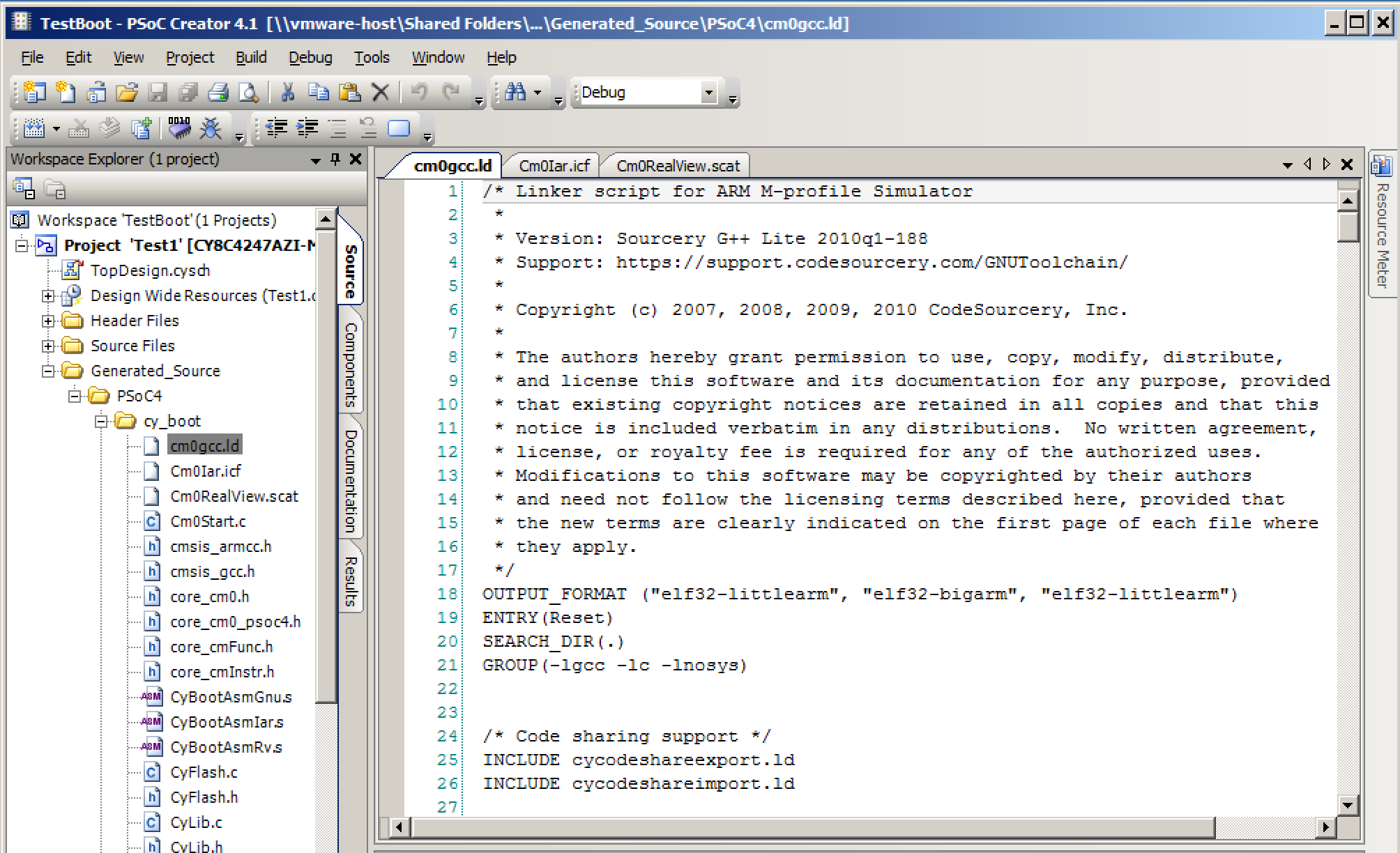
What in the world is this “__libc_init_array()”. If you look in “Cm0Start.c” on line 219 you will see this block of code. That means it is somewhere in some library (and not in this file).
/* The static objects constructors initializer */
extern void __libc_init_array(void);
My first thought was that it had something to do with initializing variables, but I realized that we had already done that. So, what does it do? And how in the world does it call “initialize_psoc()” and where does it come from? I started the search by right clicking on it and having PSoC Creator take me to the definition. But, no luck, for some reason we didn’t include the source code for that function. So, what does the function do?
Well, start by running the debugger and placing a breakpoint at “__libc_init_array”. When you do that, you can look at the assembly language. This is the place that I ended up spending a bunch of time as I had never written ARM assembly, and in fact the last time that I wrote any material amount of assembly was at Georgia Tech 26 years ago.
As I often do, I started by reading a few books and a Cypress application note. Then I spent a few days writing simple C, compiling it, and looking at the results. Specifically
- “Embedded Systems with ARM Cortex-M Microcontrollers in Assembly Language and C” by Dr. Yifeng Zhu
- “ARM Assembly Language – Fundamentals and Techniques”, William Hohl & Christopher Hinds
- “AN89610 – PSoC® 4 and PSoC 5LP ARM® Cortex® Code Optimization“
Finally I was ready to dig back into this crazy code. This function has three sections:
- 0x0620 –> 0x0x0630 is a loop that loads an array of function pointers, then makes the function call to each one (line 0x0636)
- 0x063c is a call to a function called “_init” (which I don’t know what it does)
- 0x0640 –> 0x0x0658 is a loop that loads an array of function pointers, then makes the call to each one (line 0x0654)
0x00000620 <__libc_init_array>:
0x00000620 ldr	r3, [pc, #38]	; (65c <__libc_init_array+0x3c>)
0x00000622 push	{r4, r5, r6, lr}
0x00000624 movs	r5, #0
0x00000626 adds	r6, r3, #0
0x00000628 ldr	r4, [pc, #34]	; (660 <__libc_init_array+0x40>)
0x0000062A subs	r4, r4, r3
0x0000062C asrs	r4, r4, #2
0x0000062E cmp	r5, r4
0x00000630 beq.n	63c <__libc_init_array+0x1c>
0x00000632 lsls	r3, r5, #2
0x00000634 ldr	r3, [r6, r3]
0x00000636 blx	r3
0x00000638 adds	r5, #1
0x0000063A b.n	62e <__libc_init_array+0xe>
0x0000063C bl	6d8 <_init>
0x00000640 ldr	r3, [pc, #20]	; (664 <__libc_init_array+0x44>)
0x00000642 movs	r5, #0
0x00000644 adds	r6, r3, #0
0x00000646 ldr	r4, [pc, #20]	; (668 <__libc_init_array+0x48>)
0x00000648 subs	r4, r4, r3
0x0000064A asrs	r4, r4, #2
0x0000064C cmp	r5, r4
0x0000064E beq.n	65a <__libc_init_array+0x3a>
0x00000650 lsls	r3, r5, #2
0x00000652 ldr	r3, [r6, r3]
0x00000654 blx	r3
0x00000656 adds	r5, #1
0x00000658 b.n	64c <__libc_init_array+0x2c>
0x0000065A pop	{r4, r5, r6, pc}
0x0000065C .word	0x000006e4
0x00000660 .word	0x000006e4
0x00000664 .word	0x000006e4
0x00000668 .word	0x000006ec
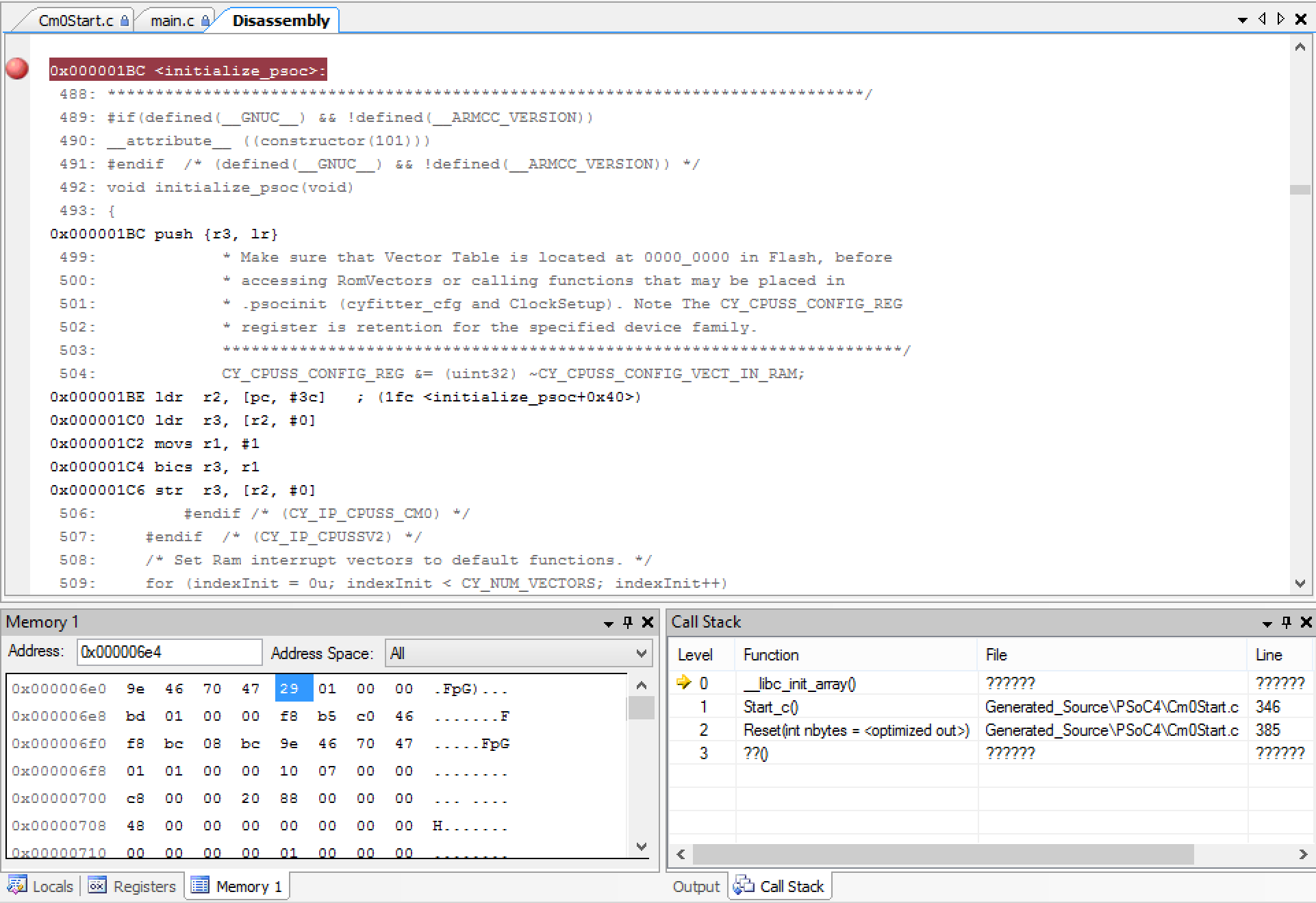
What all of this means is that there are two arrays of function pointers. The first array starts a 0x06e4 and ends at 0x6e4 (in other words it is empty). The second array starts at 0x06e4 and ends at 0x06ec which means there are two function pointers.
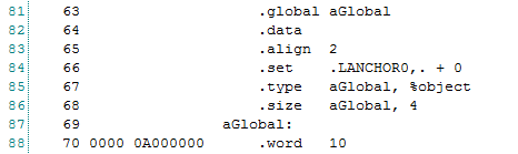
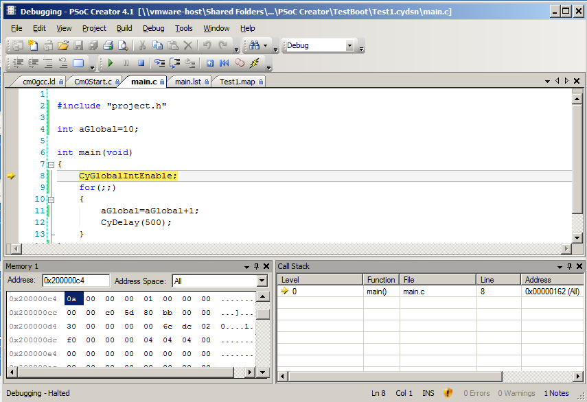
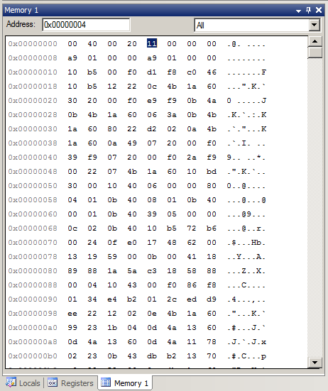
When I look at the memory location 0x06e4 –> 0x06ec you see that there are two address 0x0129 and 0x01bc. (look at the memory window in the picture below). When I scroll the assembly window to location 0x01bc, look what I find, “initialize_psoc”.
After all of that, I did what I probably should have done originally. I googled “__libc_init_array source”. One of the first few google hits was a link to the source code from CodeSourcery. And it is indeed what I said it was:
- A loop (lines 32-34) with function pointer calls
- A call to “_init” (line 36)
- Another loop (lines 38-40) with function pointer calls
/*
 * Copyright (C) 2004 CodeSourcery, LLC
 *
 * Permission to use, copy, modify, and distribute this file
 * for any purpose is hereby granted without fee, provided that
 * the above copyright notice and this notice appears in all
 * copies.
 * This file is distributed WITHOUT ANY WARRANTY; without even the implied
 * warranty of MERCHANTABILITY or FITNESS FOR A PARTICULAR PURPOSE.
 */

/* Handle ELF .{pre_init,init,fini}_array sections.  */
#include <sys/types.h>

#ifdef HAVE_INITFINI_ARRAY

/* These magic symbols are provided by the linker.  */
extern void (*__preinit_array_start []) (void) __attribute__((weak));
extern void (*__preinit_array_end []) (void) __attribute__((weak));
extern void (*__init_array_start []) (void) __attribute__((weak));
extern void (*__init_array_end []) (void) __attribute__((weak));

extern void _init (void);

/* Iterate over all the init routines.  */
void
__libc_init_array (void)
{
  size_t count;
  size_t i;

  count = __preinit_array_end - __preinit_array_start;
  for (i = 0; i < count; i++)
    __preinit_array_start[i] ();

  _init ();

  count = __init_array_end - __init_array_start;
  for (i = 0; i < count; i++)
    __init_array_start[i] ();
}
#endif
Now I need to figure out how the address of the function “initialize_psoc” got into the memory in the table.
__attribute_((constructor(101)))
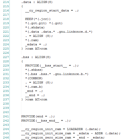
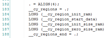
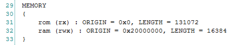
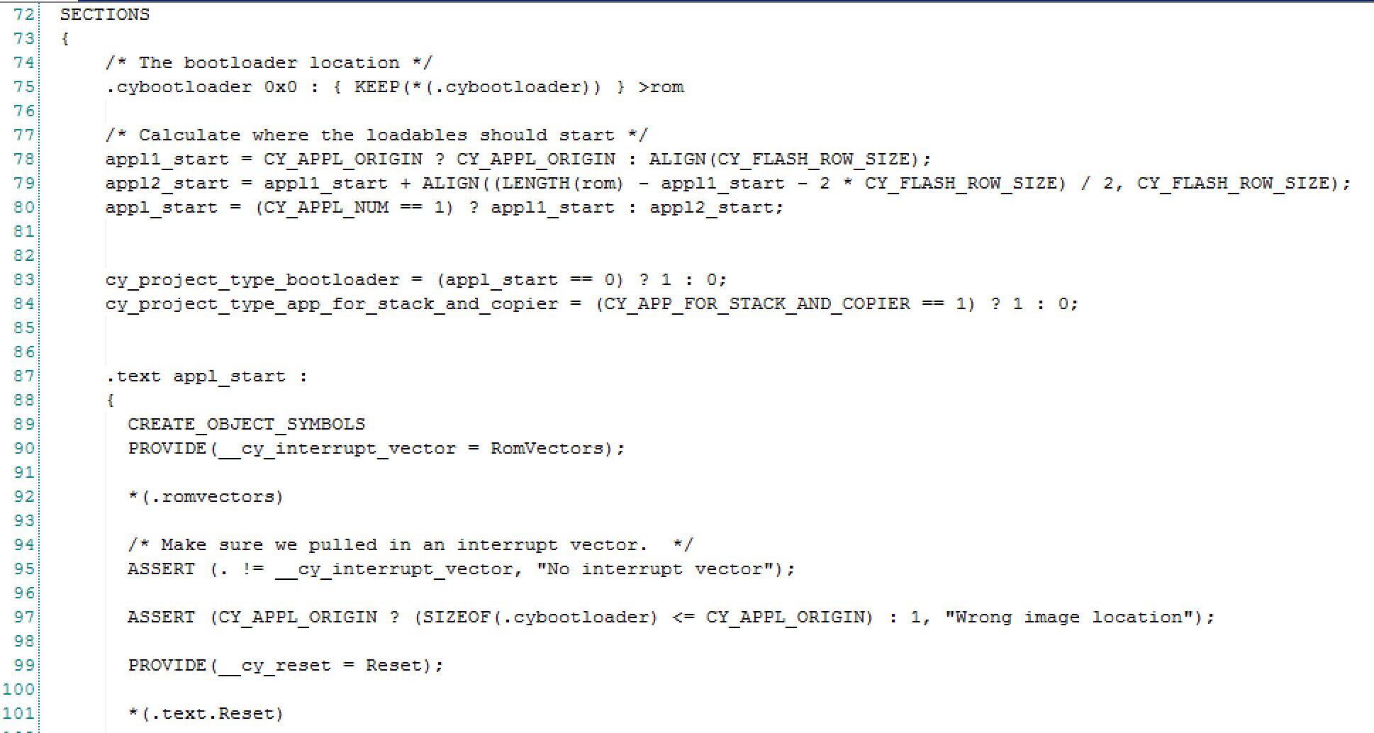
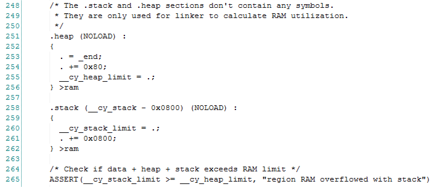
In the function “_libc_init_array” (above) it iterates through all of the function pointers that are in the array that starts at “__init_array_start” and ends at “__init_array_end”. If you look at the linker script you will see that it puts the address of every function that is in the section ending with “.init_array.*” That is cool but how does “intialize_psoc” get in that section?
      . = ALIGN(4);
      KEEP(*(.init))

      . = ALIGN(4);
      __preinit_array_start = .;
      KEEP (*(.preinit_array))
      __preinit_array_end = .;

      . = ALIGN(4);
      __init_array_start = .;
      KEEP (*(SORT(.init_array.*)))
      KEEP (*(.init_array))
      __init_array_end = .;

      . = ALIGN(4);
      KEEP(*(.fini))

      . = ALIGN(4);
      __fini_array_start = .;
      KEEP (*(.fini_array))
      KEEP (*(SORT(.fini_array.*)))
      __fini_array_end = .;
Well… if you look at the “initialize_psoc” function in Cm0Start.c you see a bunch of compiler garbly-gook. It says if you are using the GNU compiler that you should add the attribute “constructor(101)” to the function.
/*******************************************************************************
* Function Name: initialize_psoc
****************************************************************************//**
*
* This function is used to initialize the PSoC chip before calling main.
*
*******************************************************************************/
#if(defined(__GNUC__) && !defined(__ARMCC_VERSION))
__attribute__ ((constructor(101)))
#endif /* (defined(__GNUC__) && !defined(__ARMCC_VERSION)) */
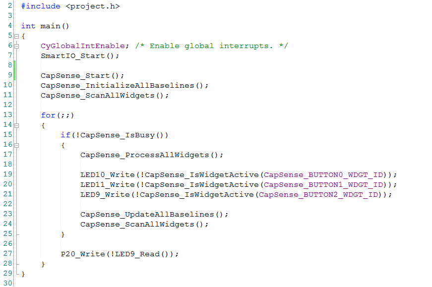
void initialize_psoc(void)
{
But what does the “constructor” attribute do? The answer to that can be found in the ARM Information Center. Basically it says that it will call all functions with that attribute before main in the order of the attribute value (in this case 101). The compiler achieves this objective by putting the function in the “.init_array” section. Then the linker does its magic.
As I said earlier in this post I am really not a fan. There is absolutely no reason why we should not have just called “initialize_psoc” right before we call “main”. This would have greatly simplified this file as there must be a similar trick going on with IAR and MDK (but I am not going to go figure it out). In addition hardcoding that 101 means that someone else might slam into it unexpectedly.
Oh well. In the next article I will talk about what initialize_psoc actually does.
Article
Description
PSoC4 Boot Sequence (Part 1) - Debugging to the Reset Vector
An introduction to the PSoC4 Boot Sequence
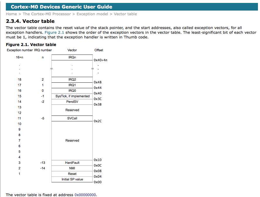
PSoC4 Boot Sequence (Part 2) - Creating the Exception Table using the Linker
Building the exception vector table
PSoC4 Boot Sequence (Part 3) - Preinitializing Variables before main()
Initializing BSS and Data
PSoC4 Boot Sequence (Part 4) - Linker trickery with __attribute_((constructor(101)))
Running initialize_psoc()
PSoC4 Boot Sequence (Part 5) - Initialize PSoC