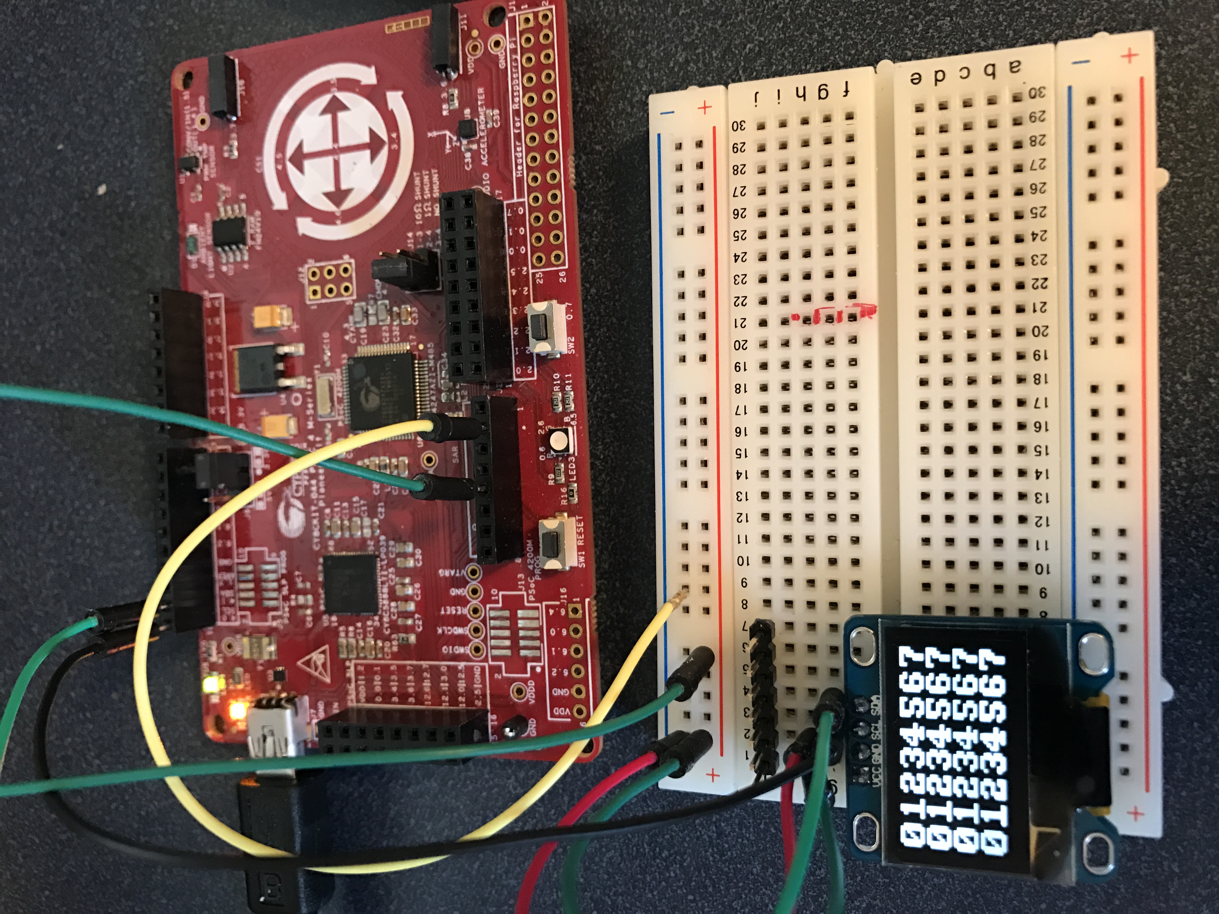
I screwed up the Pinball board design AGAIN!!! It is so frustrating. Ill write about the new design soon (and punish myself for the error.) As I worked on redoing the design I decided to put a footprint on the PCB for a small OLED LCD. The display has an I2C interface, is about an inch wide and has 128×64 pixels… But, best of all can be purchased on eBay from China for about $3.00. Here is a picture of the display with a PSoC4M driving it:
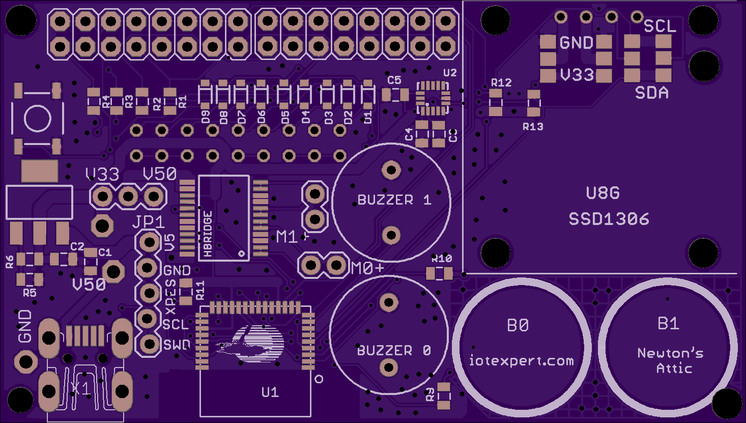
The display will go on the right side of the board. Here is a rendering of the new board from the OSH Parks website:
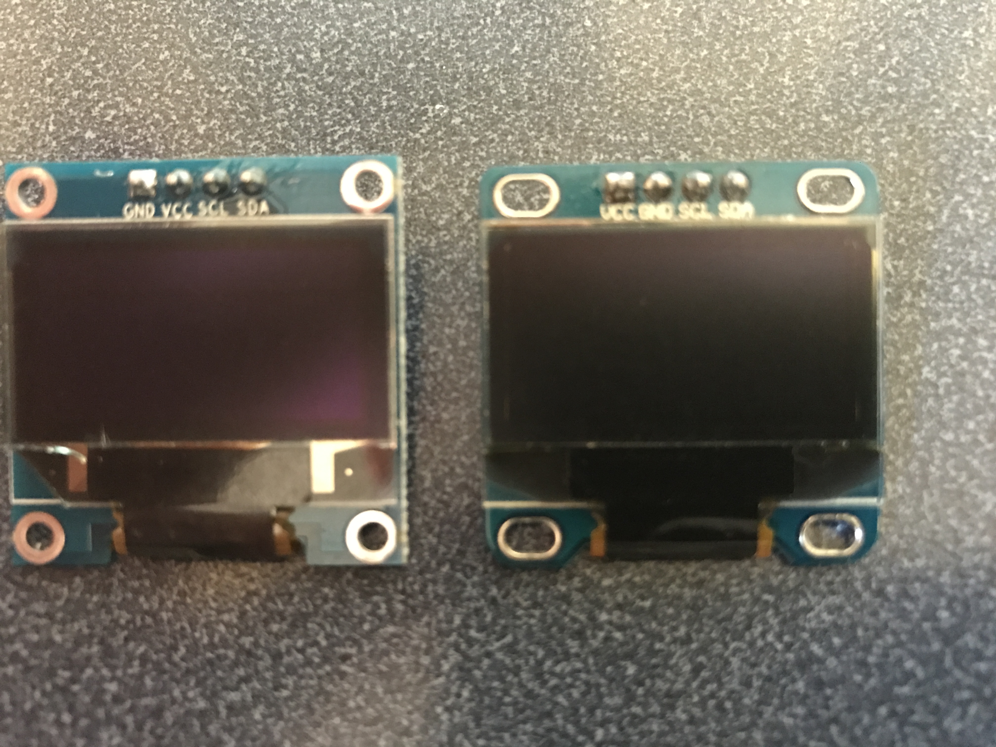
After I decided to put the footprint on the board I bought several displays from Amazon to try out, and to make sure that I knew how to make them work. I immediately ran into some drama which caused me an evening of frustration. If you look at the picture closely you can see that the power and ground pins are swapped:
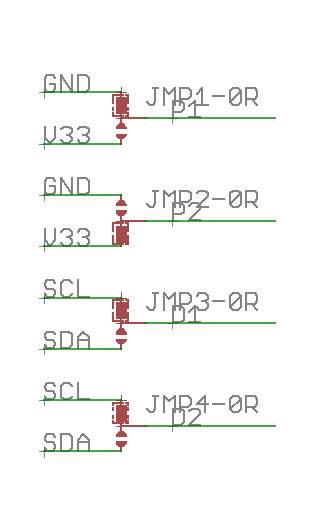
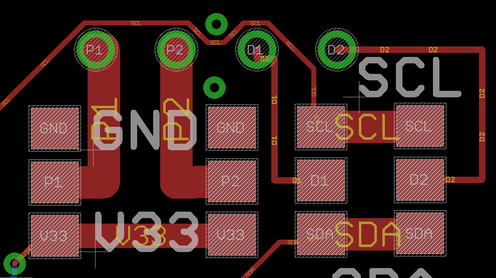
After I realized that was going to be a potential problem I put in a set of 0 ohm resistors on the upper right hand part of the board so that I could swap power/ground and scl/sda connections. Here is a snapshot of the schematic and layout:
This left me with what software to use to drive the display which I will address in the next post.
No comment yet, add your voice below!