In the previous post I built a 3-bit counter that is clocked by the PWM. In this example I will show you how to make the same design work with an external clock. It seems like it would be cool to use the CapSense Button to provide the clock. I will start by copying SmartIOCountUp to a new project called SmartIOCountUpExtClock.
First, I delete the clock and PWM. Then add a new digital output pin (P20) that I can toggle from the CapSense handler and a digital Input pin (P21) to clock the SmartIO. I add a wire between them on the female header on the board.
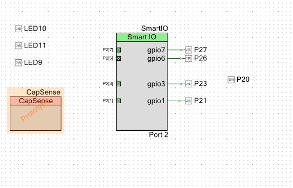
The next step is to modify the SmartIO. I change data4 and data5 to bypass. Then make gpio1 an input and then set the Clock to gpio1. Here is what the new SmartIO configuration looks like:

And the schematic.
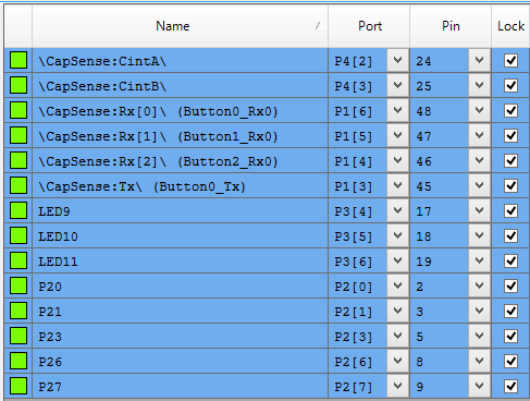
Assign the pins.
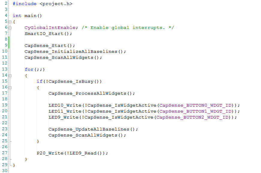
I need to update the main.c write the CapSense button to P20 to be a clock source for the SmartIO
After I program the board, I can “clock” my statemachine with CapSense Button2. Cool. Obviously this example is a bit contrived in that I am running a wire on the outside of the chip, but you could imagine that you might have a “real” example that uses an onboard clock source.
You can find this PSoC Creator workspace on github in the directory called “SmartIO”. This project is called “SmartIOCountUpExtClock”.
Index
Description
PSoC4000s & The SmartIO – Part 1
An introduction to the SmartIO and first project
PSoC4000s & CSX Mutual CapSense Buttons Part 1
Using mutual capacitance
PSoC4000s & CSX Mutual CapSense Buttons Part 2
Using the CapSense tuner
PSoC4000s & The SmartIO – Part 2
A 3 input XOR logic gate
PSoC4000s & The SmartIO – Part 3
A 3 bit up counter state machine
PSoC4000s & The SmartIO – Part 4
Using an external clock with the Smart IO
PSoC4000s & The SmartIO – Part 5
Triggering an interrupt
No comment yet, add your voice below!