CY8CKIT-021: The First 4 Example Projects

Recall from the last post that the CY8CKIT-021 has 6 different peripherals to attach to.  The first thing that I did with the board is build a simple example for each of the peripherals.  I built all of the projects on the PSoC4200M development board which is also known as CY8CKIT-044.  The pinout for the other kits will be different, but the PSoC projects will be the same, but with a different pin map.  Later in the week I’ll show projects for the FM0 and FM4 development kits.  All of these projects  are available at github.com/iotexpert/CY8CKIT-021 in the firmware directory and in a single workspace.

  • Example 1: 2 LEDs
  • Example 2: A buzzer
  • Example 3: A direct drive 7-segment LCD
  • Example 4: A potentiometer
  • Example 5: A thermistor
  • Example 6: 2 Capsense Buttons (using the V2.x component)
  • Example 7: 2 Capsense Buttons (using the new V3.x component + tuner)

Example 1: Two LEDs

This weekend I taught people at the Bay Area Maker Faire to program PSoC.  I told them that the first project that you always do is the blinking LED.  This simple project is perfect to show that the tools work etc.  So, that is what we will do here.  For this example I used a TCPWM to blink the two LEDs.  One LED is connected to the line output and the other one is connected to the line_n output.  This will cause the LEDs to alternate.  The only other slightly interesting thing that I do is put the CPU to sleep and just let the hardware do the blinking.


Screen Shot 2016-05-24 at 8.21.03 AM

Screen Shot 2016-05-24 at 8.23.44 AM

Screen Shot 2016-05-24 at 8.21.26 AM

Screen Shot 2016-05-24 at 8.21.43 AM

Example 2: A buzzer

To beep the buzzer I will use a 440hz tone that is generated by the TCPWM which divides an input clock of 440khz by 1000 to achieve the note “A” or “A4”.  To make the tone turn on and off I do my most hated thing, use the CyDelay to make a busy wait loop.  Basically, I turn on the PWM, wait for 500ms then turn it off, wait for 500ms and then go back to the start.

Screen Shot 2016-05-24 at 8.25.20 AM

Screen Shot 2016-05-24 at 8.25.33 AM

Screen Shot 2016-05-24 at 8.26.34 AM

Screen Shot 2016-05-24 at 8.25.53 AM

Example 3: Direct Drive 7 Segment LCD

A very cool feature of almost all of the PSoCs is their ability to drive “direct drive LCDs”.  This is a very low cost, low power way to add a display to your design.  This display we used on this board is a Lumex LCD-S401M16KR  that costs $0.73 from Mouser.  Internally, all LCDs are organized into rows and columns a.k.a Segments and Commons.  To enable a particular segment in the LCD you need to select the correct row and column.  Then to make a symbol on the screen you need to select the combination of segments for that number.  For example, from the picture below, to make a “7” on the left digit you would need to turn on C3/S1, C2/S1, and C1/S1.  This would be a serious pain in the ass, but conveniently, the PSoC Creator segment LCD component does this for you automatically.

Our Lumex display is organized into 8 Segments and 4 Commons.  This means that it takes 12 pins on the chip and can show 32 segments.  The segments are organized into 4 characters with 7 segments (28 total segments), a decimal point between each character (3 segments) and a colon. Here is a picture:

Screen Shot 2016-05-24 at 8.53.59 AM

First add the segment LCD component to your design and attach a clock

Screen Shot 2016-05-24 at 9.17.07 AM

Then make the top level configuration (4 commons and 8 segments)

Screen Shot 2016-05-24 at 9.17.15 AM

To configure the component display you need to first add a “7 segment” helper to your component by selecting it and then clicking the right arrow.  Then you click the “+” 4 times to add 4 digits to your design.  Then you need to drag and drop the each segment from the digits onto the correct location on the segment/common matrix in the “pixel mapping table”.  For example “Common 3 / Segment 1” or “C3/S1” is the top segment in the left digit (look at the picture above), it needs to go in the “Com3” column and the “Seg1” row.  There is a pattern and once you see it this will not take very long.

Screen Shot 2016-05-24 at 8.40.52 AM

The next step is to add the decimal points and colons to your project.  To do this add a “barograph and dial” helper.  Then click the “+” 4 times so that you have 4 segments.  As you add each one give it an appropriate name e.g. “colon” or “dp1”

Screen Shot 2016-05-24 at 8.41.05 AM

The last thing that you need to do is to assign the pins.

Screen Shot 2016-05-24 at 9.16.50 AM

The firmware is simple:

Screen Shot 2016-05-24 at 9.25.13 AM

Example 4: The Potentiometer

To test the potentiometer I will use the ADC to measure its output voltage and then display it on the LCD screen.

Screen Shot 2016-05-24 at 9.50.55 AM

Screen Shot 2016-05-24 at 9.51.39 AM

Screen Shot 2016-05-24 at 9.51.51 AM

Screen Shot 2016-05-24 at 9.52.11 AM

I am out of time… so in the next post Ill show examples 5,6,7

Alan

index description
CY8CKIT-021: A Simple FM/PSoC + BLE Demonstration Board Introduction to CY8CKIT021
CY8CKIT-021: The first four example projects Use the LEDs Buzzer 7-Segment display and the Potentiometer
CY8CKIT-021: The next three example projects Use theThermistor and two Capsense Examples
CY8CKIT-021: Bootloading the PRoC How to put firmware into the PRoC
CY8CKIT-021: The BLEIOT Component A custom component to communicate with the PRoC/PSoC
CY8CKIT-021: Using the BLEIOT Component A full example of the tho MCUs talking
CY8CKIT-021: The PRoC BLE Firmware How to make PRoC Firmware and use it with the BLEIOT Component
CY8CKIT-021: Example 10 - the new IOS App How to build and IOS App to talk to the development kit

CY8CKIT-021: A Simple FM/PSoC + BLE Demonstration Board

In my job I spend a lot of time teaching people how to use Cypress Products.  One of the best students that I ever had was Paul Bentley the Cypress VP of Sales for Europe.  He came to Kentucky a few years ago to take my class.  He dove in with reckless abandon and did a amazing job learning how to actually program the PSoC (not just talk about it on powerpoint).  Recently, he was anointed with the responsibility to teach more of our Sales team to use PSoC at the Sales Technical Conference (STCON) which is going on this week.

For some time I have wanted a very simple, inexpensive board to help teach people how get going using our chips…. all of our chips both the FM products as well as the PSoC products.  The STCON afforded the perfect opportunity to build an education board.  I am very lucky to work with some really good people (in India and New Hampshire) who did the work of realizing the vision of a simple board and getting it made in short time.

Without further ado, here it is, the provisionally name CY8CKIT-021 PSoC and FM Starter Shield (shown connected to the CY8CKIT-044).

imageThe shield has an Arduino compatible footprint and has:

  • 2 CapSense Buttons
  • A Potentiometer
  • A Thermistor
  • 2 LEDs
  • A PRoC BLE Module
  • A Piezo-electric buzzer
  • A 7 Segment direct drive LCD

The PRoC is connected to the USB-I2C bridge on the programmer as well as the serial (I2C/UART) pins on the base board.  Here is the schematic:

Screen Shot 2016-05-23 at 6.53.13 AM

One of the cool things about this board is that it is generally compatible with a bunch of the Cypress products including:

  • CY8CKIT-042
  • CY8CKIT-042-BLE
  • CY8CKIT-044 (which is shown in the picture above)
  • CY8CKIT-046
  • S6E1B8
  • S6E1C3

Over the next several days I am going to show you example projects using the board.  I will culminate at the end of the week by IOTifying the board by writing BLE firmware for the PRoC, building an IOS app and an Android app to talk to the board.

index description
CY8CKIT-021: A Simple FM/PSoC + BLE Demonstration Board Introduction to CY8CKIT021
CY8CKIT-021: The first four example projects Use the LEDs Buzzer 7-Segment display and the Potentiometer
CY8CKIT-021: The next three example projects Use theThermistor and two Capsense Examples
CY8CKIT-021: Bootloading the PRoC How to put firmware into the PRoC
CY8CKIT-021: The BLEIOT Component A custom component to communicate with the PRoC/PSoC
CY8CKIT-021: Using the BLEIOT Component A full example of the tho MCUs talking
CY8CKIT-021: The PRoC BLE Firmware How to make PRoC Firmware and use it with the BLEIOT Component
CY8CKIT-021: Example 10 - the new IOS App How to build and IOS App to talk to the development kit

Maker Faire – Bay Area

IMG_2820

I am at the Maker Faire this weekend teaching people how to  program the PSoC.  We have a bunch of computer runnings PSoC Creator and I am giving out development kits.

Come to the Cypress booth and signup and I will teach you!


The Creek: Install the Raspberry PI Software

Years ago, when I did the first install of a Raspberry Pi (RPi), this whole thing was quite painful, however at this point the installation process is well documented.  In addition adafruit.com has a nice tutorial about making the I2C work here.

To start the process download the Raspbian image from it from here.

Screen Shot 2016-04-02 at 8.50.41 AM

Because I talked so much about security in this post, I thought that I had better check the cryptographic hash.  So, I run

  • openssl sha1 2016-03-18-raspbian-jessie.img

And I get:

SHA1(2016-03-18-raspbian-jessie.img)= 824f4daf805eb0ff49bc3fa515d97f447d382d37

which definitely didn’t match the signature, so now what? Is this a hack?  It turns out that my Mac “helps” you by unzipping the file.  The cryptographic hash of a file and a zip of that file are different.  If you download the zip and run the hash you will get:

SHA1(2016-03-18-raspbian-jessie.zip)= db41f2a8c6236c0ca9150fe4db2017c09e7871fb

OK.  They match.  Good.  The next step is to write the image to the flash card.  To do this

  • Insert the card (into your Mac)
  • See what disks are mounted
  • Unmount the volume (if you already had something on the card)
  • Write the image onto the flash card.  In the instructions on the Raspberry Pi site there is some confusion about if you should use /dev/rdiskx or /dev/diskx.  Thats simple, you should use the “r” version.  “r” stands for raw and is unbuffered and as such is much faster to write.  Even with the raw device it still takes a few minutes.  While it is writing you can press “ctrl-t” and it will give you a status (which I did twice during the write process)
  • Unmount the disk

Screen Shot 2016-04-02 at 9.20.38 AM

Now that you have a bootable flash disk your next step is to insert the card into your RPi, attach a keyboard, the network cable and a screen.  Then boot it.  After a few minutes you should see:

IMG_2768

The first thing that needs to be done is to change the password and expand the filesystem.  To do this run “sudo rapsi-config” then select

  • [Option 1] Expand Filesystem
  • [Option 2] Change User Password

I prefer to interact with the RPi using secure shell from my Mac.  To do this I need to know what IP address was assigned by my DHCP server.  So, start a terminal on the Pi and type:

  • ifconfig (find the ip address and the ethernet mac address)

Once I know the ethernet mac address I can configure my DHCP to always give this Raspberry Pi the same IP address.  You can read more about this in the “Creek Network” post.  For now I will assign the RPi the address 192.168.15.82 and I will add that address to the /etc/hosts file on my Mac so I can refer to it by the name “iotexpertrpi”

Now that all of the networking is setup, reboot.  As I have configured the IP address I can now log in using secure shell and start the configuration process.

  • [from the Mac] ssh pi@iotexpertpi (you will need to type the password which is “raspberry”)
  • [on the pi] mkdir .ssh
  • [on the pi] chmod 700 .ssh
  • [on the pi] exit
  • [from the Mac] cd ~/.ssh
  • [from the Mac] scp id_rsa.pub pi@iotexpertpi:.ssh/authorized_keys (you will need to type the password)

Then, to test SSH I will exit and log back in.  After the secure shell is going I need turn on the stuff in the configuration that enables I2C.

  • [on the pi] sudo apt-get install i2c-tools

In order for the I2C work you also need to enable the kernel drivers for I2C.  To do this run “[on the pi] sudo raspi-config”

Screen Shot 2016-04-02 at 9.53.12 AM

Screen Shot 2016-04-02 at 9.53.25 AM

Screen Shot 2016-04-02 at 9.53.39 AM

Screen Shot 2016-04-02 at 9.53.52 AM

After I2C is setup I will change the RPi to not start X-Windows.

Screen Shot 2016-04-02 at 9.56.10 AM

Screen Shot 2016-04-02 at 9.56.22 AM

After all of that, reboot the RPi and see if things are working.

  • [on the Mac] ssh pi@iotexpertpi
  • [on the pi] i2cdetect -y 1  (the 1 means bus 1.  On the Broadcom chip there are 2 IC Masters which they have labeled 0 and 1.  Apparently they did not connect Master 0 to anything)

This is good.  I can “search” all of the addresses.  Basically the RPi tries to write each address.  If it gets an “ack” then it will indicate that on the chart with a number.  In the picture below you can see that there are no I2C devices attached to the bus.

Screen Shot 2016-04-02 at 10.09.41 AM

Everything looks good.  Halt the RPi then attach the CYPI board and reboot.

IMG_2770

Now, when I log back in and run “i2cdetect -y 1” lookey there, the CYPI “ACKs” on address 08.

Screen Shot 2016-04-02 at 10.27.45 AM

If you remember in this post I talked about the I2C register structure of my Creek Firmware.  In the two bytes starting at location 2, is a 16-bit integer of the temperature times 100 (I just noticed the error in my comment, bad Alan).  Here is the register structure:

DataPacketFormat

In I2C tools, the command “i2cget” can read bytes or words from an I2C Slave.  Are things working?  Run “i2cget -y 1 8 2 b” and “i2cget -y 1 8 2 b” and I get 0x10 and 0x09 or 0x0910 (remember that the data is stored little endian) which is 2310 in decimal or 23.1 degrees C.  That makes sense.  What is a bit confusing is when I read a whole word by changing the “b” to “w” it gives it to me correctly because it ASSUMES little endian, so be careful if your slave device doesnt store thing little endian.

Screen Shot 2016-04-02 at 10.39.32 AM

Everything seems like it is working.  In the next posts I will discuss the installation of the MySql, Tomcat and the rest of the server software.

Index Description
The Creek: IOT for the Elkhorn Creek Introduction
The Creek: Solution Architecture 1.0 Overall architecture
The Creek: Creek Board 1.1 Eagle layout of the board
The Creek: Creek Board 1.0 – RCCA A discussion of the errors in the 1.0 board
The Creek: CYPI, a Raspberry Pi to Arduino Bridge PSoC4 <--> Raspberry Pi Bridge Board
The Creek: PSoC4 Creator Schematic and Firmware Firmware to interface with the temperature and pressure sensors
The Creek: Testing the Firmware Using tools to verify that the PSoC 4 Firmware is working correctly
The Creek: Testing the Bootloader Make sure that you can load new firmware into the PSoC
The Creek: Software Architecture All of the Raspberry Pi software connections
The Creek: Install MySql Instruction to configure MySql
The Creek: Install Tomcat Instruction to configure Tomcat JSP Server
The Creek: Data Collection Java (Part 1) The Java program that reads the I2C and saves it in the database
The Creek: Data Collection Java (Part 2) The Java program that reads the I2C and saves it in the database
The Creek: Create the Chart with JFreeChart Using open source Java charting software to create plots of the Creek Depth
The Creek: Flood Event Data Processor A batch program to create analyze the database and create a table of flood events
The Creek: Flood Event Web Page A batch program to create the flood event web page
The Creek: Creek Server 1.1 Updates to all of the back off server programs to integrate charts
The Creek: JSP Web Page for www.elkhorn-creek.org The JSP program to make the table and display the website
The Creek: Raspberry Pi Clock Stretching Sorting out a bug in the system having to do with the Broadcomm Raspberry Pi Master not functioning well with clock stretching
The Creek: Creek Server 1.2 Caching the web pages to make them faster

The Creek: Meraki Network

I have very mixed emotions about posting a diagram of the network at my house.  On one hand the network is super cool and lets me do all kinds of interesting things so I think a lot of people will be interested in it.  On the other hand giving information that could be used by hackers might not be such a good idea.  I don’t think I am giving away to much crucial information, but I don’t know that to be the case.

OK.  Here it is.  I use a bunch of Meraki networking equipment from Cisco.  Meraki is a cloud managed infrastructure company that was bought by Cisco in 2012.   Cisco seems to position it for smallish companies who need first class networking but don’t have lots of people to support it.  Cisco handles all of the patching, network maintenance, etc. but you still have complete control to do about whatever you want.  In my case, it can do more things that I am capable of doing.

I wanted a network that could:

  • Provide a wide physical area of WiFi coverage (I live out in the country in lots of space)
  • Provide private and public WiFi on separate VLANs
  • Wirelessly extend both the WiFi and the ethernet network into the barn
  • Traffic shape all of the networks onto the Internet
  • Manage my children access to the Internet
  • Provide excellent firewall services

I have a close friend who works at Cisco as an Application Engineer who convinced me to choose Meraki.  Overall I am sure that there is a premium that you need to pay, but it works great and is easy to learn and administrate.

First the physical diagram:

meraki-physical-a

The MR60W was designed to be a complete small office solution.  It has

  • 5 ports of 1G ethernet
  • WiFi (Both 5G Hz and 2.4GHz)
  • Firewall
  • Connection to Internet

The MR60W has been superseded by the MR64W, Cisco appears to have removed the MR60W product landing page from their website or I would have linked to it, but I did find a review here.  They call this the “security appliance” as it is the principal device in securing your network.

The MS22P (which has also been obsoleted) is a 24 port, power-over-ethernet, gigabit ethernet switch.  It supports all of the switching things that I needed to do to have separate VLANs.  This looks like it has been replaced by the MS220-24.  In my office I have several devices that I run on wired ethernet including a couple of MACs, and a 17TB dual ethernet Segate RAID box.

The MR66s are outdoor access points that I use to

  • Bridge between the Barn and my house (they have Yagis)
  • Provide Wifi in the barn and around the back of my house
  • Provide ethernet in the Barn

This is a picture of the access point attached to the side of my porch.  You can see the Yagi antenna on the left.

IMG_2781

This is a picture of the “other end” of the bridge.  The Yagi points towards my house and the other Yagi.

IMG_2783

The MR16 is is a WiFI access point (that has been superseded by the MR18).  It is located in the far corner of my upstairs and provided Wifi for the front part of the house.  It runs off of Power-over-Ethernet (which made it easy to install).

Configuration

When you enter the Meraki control website there are an unbelievable number of configuration and monitoring screens that you have access to.  Here are a few of the menus:

Screen Shot 2016-04-07 at 5.39.04 AM

The “Cients” menu give you this screen where you can monitor the clients that are accessing your network and whitelist or blacklist them.  Notice that I have two unknown people who joined the guest network blocked (probably the neighbors kids).

clients

This menu gives you access to all of the configuration settings of your network including VLANs, Wireless network, DHCP etc.  The system will also allow you to create VPN tunnels between offices.

Screen Shot 2016-04-07 at 5.39.13 AM

Here is the DHCP screen.  You can see that I have a number of “fixed” IP assignment based on ethernet mac addresses.

dhcp

This menu has global settings about your network, for instance the Administrators menu where you can configure everyone who is allowed to log into the management web page.

Screen Shot 2016-04-07 at 5.39.22 AM

This menu allows you to control the switches on your network.

Screen Shot 2016-04-07 at 5.39.52 AM

Here is a screenshot of the MS22P Ethernet Switch:

m22p

This menu allows you to control your wireless networks.

Screen Shot 2016-04-07 at 5.40.00 AM

Here is the screen that shows the status of one of the WiFi Access Points

mwireless

All in all the network works very well.  Send me an email or leave a comment if you have a question.

Git and SSH

Summary

In a previous post I talked about the steps I took to repurpose my old Mac Mini as a server.  In this post I will explain the steps that I went through to make it act as a “Git” server.  Although I am an active github.com user it is sometimes nice to have something stored locally as well.  The easiest (and best) way to make a git server on your network is to use SSH.  In order to make SSH work you need to know about encryption and keys.  I knew in an abstract way about encryption but I hadn’t really dug through how all of the parts operate in detail which I had to do to figure this out.  I will start by explaining the practical mechanics of encryption, and then take you through the rest of the steps to setup and use Git.

  1. Symmetric and Asymmetric Encryption: A Foundation
  2. Setup Git as user on your Server
  3. Create RSA Keys for a User
  4. Give user permission to write into Git User Account
  5. Create a new repository called “repoName”
  6. Using the new repository

Symmetric and Asymmetric Encryption: A Foundation

SSH stands for Secure SHell.   The reason it is called Secure is that it uses an encrypted channel for all communication.  But how can that be?  How do you get a secure channel going?  And what does it mean to have a secure channel?  What is secure?  This could be a very complicated topic as establishing a fundamental mathematical understanding of encryption requires competence in advanced mathematics that is far beyond most everybody on the face of this planet.  It is also beyond what there is room to type in this blog.  It is also far beyond what I have the ability to explain.  But, don’t despair.  The practical aspects of getting this going are actually pretty simple.

First a word of caution.  When you make the changes to your computers/network to make this stuff work, you are playing with fire.  If you are not careful, you will compromise the security of your system.  At this point all of the computer and operating system vendors have spent considerable amounts of time and money making computers safer by installing firewalls and closing security holes.  For as much as they have spent making security, the fucking hackers, the Chinese government and the assholes in US government have put 10x that energy into trying to steal your information.

All encryption does the same thing.  It takes un-encrypted data, combines it with a key, and runs it through an encryption algorithm to produce encrypted data.  You then transmit the encrypted data over the network.  When the other side receives the data it decrypts the encrypted data by combining it with a key, and running the decrypt algorithm.

There are two types of encryption schemes, symmetric and asymmetric.

Symmetric means that both sides use the same key.  That is, the key that you encrypt with is the same as the key you unencrypt with.  Examples of this type of encryption include AES and DES.  This type of encryption is preferred because it is very fast and secure.  However, both sides need to know the key before you can use it.  If you have never talked before how do you get both sides to know the key?  This is a big problem.

Asymmetric, often called Public Key, encryption techniques use two keys that are mathematically related.  The keys are often referred to as the “public” and the “private” keys.  The private key can be used to decrypt data that the public key encrypted and vis versa.  This is super cool because you can give out your public key to everyone, they can encrypt data, then only your private key can be used to decrypt it.  The problem with this encryption technique is that it is slow.

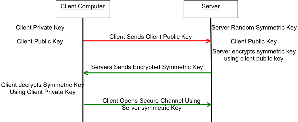
What now?  The most common technique to communicate is to

  • You open an unencrypted connection to a server
  • You give out your public key to the server
  • The server then creates a random symmetric key
  • The server then encrypts its newly created random symmetric key using your public key and sends it back to you
  • You use your private key to decrypt the symmetric key
  • You open a new channel using symmetric key encryption

public-key-exchange

This scheme is completely effective against eavesdropping.  What happens if someone eavesdrops the original public key?  That is OK because they won’t have the “client private key” required to decrypt the symmetric key.  What this scheme doesn’t work against is called man-in-the-middle (MIM).  An MIM attack works by

  • You open an unencrypted connection to a server [but it really turns out that it is a MIM]
  • You send your public key to the MIM
  • The MIM opens a channel to the server
  • The MIM sends its public key to the server
  • The Server encrypts a symmetric key using the MIMs public key and send it back to the MIM
  • The MIM decrypts the symmetric key using its private key
  • The MIM send you the symmetric key encrypted with your public key
  • You unencrypt the MIM symmetric key using your private key
  • Then you open new channel to the MIM using the symmetric key
  • The MIM opens up a channel to the server using the symmetric key

Once the MIM is in the middle it can read all of the traffic.  You are only vulnerable to this attack if the MIM gets in the middle on the first transaction.  After that things are secure.  However, the MIM can easily happen if someone gets control of an intermediate connection point in the network-like e.g. WIFI access point.  The only way to protect against MIM attacks is to have a Certificate Authority (CA).  A CA works by verifying that the Public Key actually belongs to who you think it belongs to by using a cryptographic hash.  If the MIM sends you its public key then you check with the CA and find out that the MIM public key does not belong to the server that you are trying to connect to, then you know that you are being subjected to an MIM attack.  How do you prevent an MIM when talking to a CA?  This is done by building in known valid certificates into your program.   This morning when I looked at the certificates on my Mac there were 179 built in, valid certificates.  This is cool for HTTPS but what about SSH?  With SSH you will need to manually verify the public key of the host you are attaching to.  There is a nice discussion of this topic here.

When you configure your GIT server you will manually copy your public keys onto the GIT server.  This will prevent MIM attacks and will support the establishment of a symmetric encrypted connection.  This is called an out-of-band (OOB) key exchange.  On github this is done with a browser.   For other security systems it could be a USB stick or other scheme.  More on that later.  Now onto the mechanics of making the Git server work.

Setup Git as user on your Server

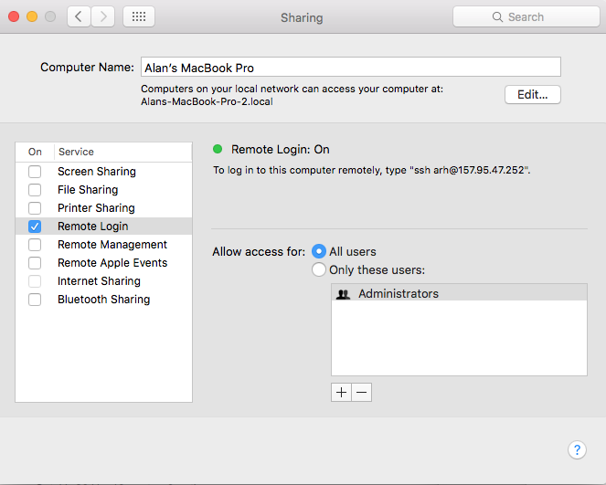
First you need to enable Remote Login (ssh) from the System Settings –> Sharing.  Make sure that it enabled for All Users

Remote Login

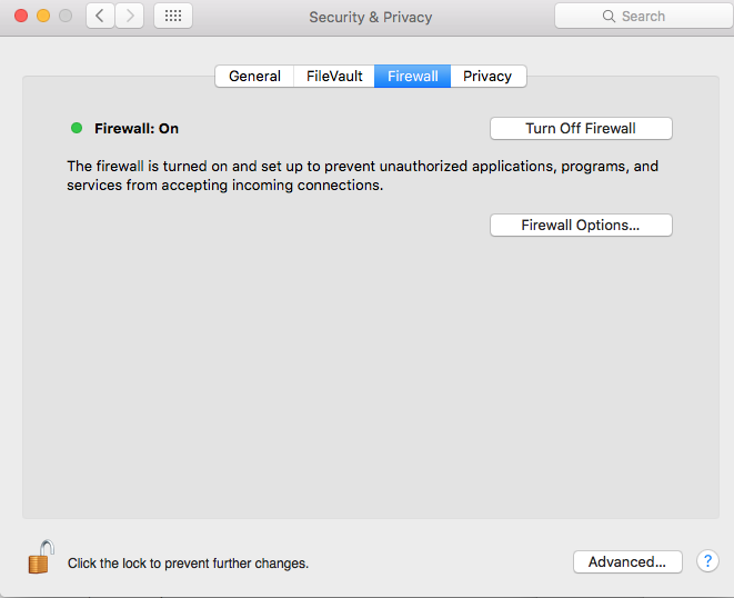
Then you need to turn on the firewall  System Settings –> Security & Privacy

Firewall

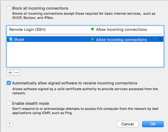
Press the “Firewall Option…” turn off the “Block all incoming connections” and then allow Remote Login (SSH)

Firewall Remote Login

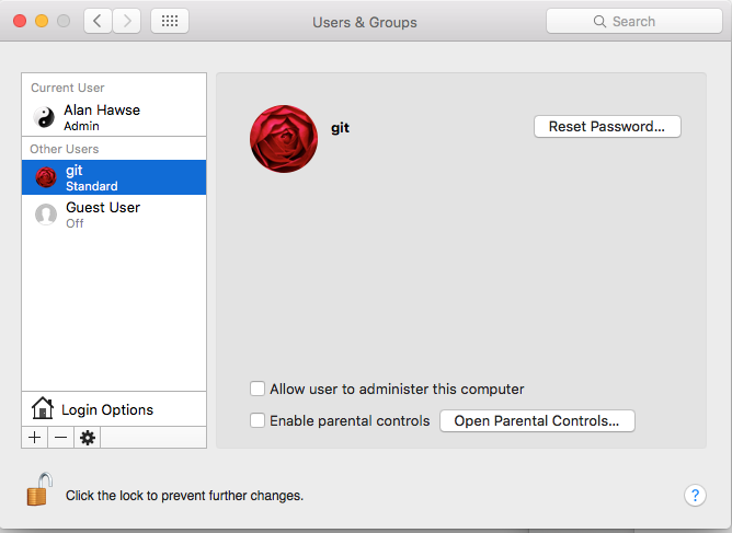
Then you need to create a “git” user account.  The account should be a standard account.

Create GIt Account

The next step needs to be done in a terminal window.  You need to have root access (your account need to be authorized as an administrator) to follow these steps.  This will create the place to store the SSH RSA Keys.

command comment
su – git log in a the git user.  You will need to type the password that you set when you setup the git account
mkdir .ssh Create the directory with the public and private secure shell keys
chmod 700 .ssh This directory should only be redable by the git user
cd .ssh
touch "authorized_keys" Create a file that you will add public keys to of the people who are allowed to upload to this server
sudo chpass -s /usr/bin/git-shell git Make the git user so that it can only do git commands.  This is a way to enhance security by not letting the git account do anything other than local git commands.

Create RSA keys for a user

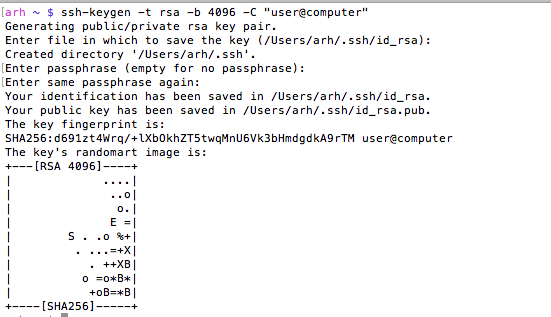
In order for a user to have access to the git account on the server he will need to have RSA Keys.  Specifically, in the ~/.ssh directory of the user you will need two files, id_rsa and id_rsa.pub  These files are the public and the private keys of the user.  When you run the command

  • ssh-keygen -t rsa -b 4096 -C “user@computer”

it will first ask you where to store the keys.  If you already have keys it will give you the option to store them someplace other than the default location.  Then ssh-keygen will ask you for the password to encrypt the private key file.  I don’t use a password on my private key file, but the security would probably be better if I did.  The “-C” option just inserts the text in quotations into the key file as a comment so that when you look at the file you can figure out what the key is associated with.

Screen Shot 2016-03-29 at 7.24.22 AM

You can look at the MD5 signature (which is what github displays) of a public key by running

ssh-keygen -E md5 -lf  id_rsa.pub

Give user permission to write into your Git User Account

In order for a user to be able to access the git server you will need to append his public key to the “~git/.ssh/authorized keys” file.  As I talked about above, in the users home directory you will find a directory called “.ssh”.  In that directory there will be two files, one is called “id_rsa.pub” which is the RSA public key, the other is called “id_rsa” which is called the private key.  You should be very careful to only copy the public key.

  • sudo cat id_rsa.pub >> ~git/.ssh/authorized_keys

In this example both users were on the same computer, but they don’t have to be.  In that case you will need to copy the file some other way (ftp, scp, the browser, …)  Then append it to the ~git/.ssh/authorized_keys file.

Create a new repository called “repoName”

Once you have everything setup with the git user and the SSH RSA keys you will need to create a “bare” repository

  • cd ~git
  • sudo git init –bare repoName.git
  • sudo chown -R git repoName.git

Using your new repository

The last thing to do is to setup git remotes for the new repository.  To do this, on your client machine you can either clone it with

  • git clone git@githost:repoName.git

Or if you have an existing repo you can

  • git remote origin git@githost:repoName.git
  • git push origin master


Other random topics

When I was trying to figure out how all of this worked I found a couple of places (on google) that talked about modifying the file /etc/ssh/sshd_config.  This turned out to be a red herring as the default Mac OS X settings work fine.

When you open a new shell on your client computer, then start your first SSH, the client shell automatically starts a daemon called “ssh-agent”.  This daemon reads all of your key information and caches it.  You can see the information that it is storing by running “ssh-add -l”.  If for some reason you change your rsa keys you will need to either restart the daemon or tell it to read the new keys “ssh-add ~/.ssh/id_rsa”.  You can read more about this in these articles ssh-agent-forwarding and ssh-agent-keys in the github documentation.

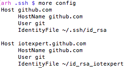
If for some reason you are using multiple rsa key files then you need to create a “~/.ssh/config” file to setup which key is used in which situation.  I have this situation because I use github for my personal stuff as well for my iotexpert stuff.   By default ssh uses the keys in “~/.ssh/id_rsa”.  If you need to setup a different key for other hosts you can:

  • Create an ssh name called “github.com” which uses “~/.ssh/id_rsa”
  • Create and ssh name called “iotexpert.github.com” which uses “~/.ssh/id_rsa_iotexpert”

Screen Shot 2016-03-30 at 7.14.13 AM

There is a daemon running called the ssh-agent.  It is used to cache and deliver the keys.  You can see what keys it knows about by running

ssh-add -L

You can delete the cache by running

ssh-add -D

You can add keys to the cache by running

ssh-add ~/.ssh/id_rsa

ssh-add ~/.ssh/id_rsa_iotexpert

To test all of this (with github) you can run

ssh -T git@iotexpert.github.com

or

ssh -T git@github.com

These commands will test the key exchange to make sure that the right key is being mapped to the correct user.

Then to setup the different remotes I do

  • git remote add origin git@github.com/someuser/repository.git to use the id_rsa key
  • git remote add origin git@iotexpert.com:iotexpert/repository.git to use the id_rsa_iotexpert key

The thing that was intensely confusing is “iotexpert.github.com” isn’t actually the name of a computer.  It is just an ALIAS that ssh uses… when SSH runs it looks in the config file and if it sees a “Host” alias that matches what you typed, then it substitutes the value of “HostName” in place of where you gave it “Host”.


Mac Mini –> Mac Server

In 2011, I bought a Mac Mini Server to act as my main desktop.  That computer had 2GBs of RAM and 2 internal 500gb hard drives.  I originally setup that computer as RAID1, meaning that the two drives were in a mirror configuration.  This meant that if one failed that I didn’t loose my data and things kept going.  As I am paranoid about my data I also had a Time Capsule that made regular backups using Time Machine.  I will admit that I am an Apple fan boy.  When I got married in 1992 the asshole photographer misprocessed the film, which resulted in all of the pictures being destroyed.  Since then, I have been really really paranoid so I also backup my backup to the Cloud using Mozy.

In the fall of 2014 I switched to using a MacBook Pro as my main computer, so I moved the Mac Mini onto my kids desk.  And, as computers seem to do, the Mac Mini became slower and slower as more crap was loaded onto it.  Earlier this year I bought them a new Mac Mini and set my old workhorse to the side.   About 6 weeks ago, I decided that I was interested in building a new cloud server and I decided to refurbish the Mac Mini as a server.

I started the process by installing two 8 GB SIMMs which I bought from MacSales.com because they have really excellent tutorials on their website.  16GB made a huge difference in the performance of the machine.  The install process is pretty simple.  The Mac just has a cover which twists off giving access to the two SIMM slots.  Here is the video tutorial that they provide

I then reinstalled the OS, which was a total pain in the neck.  At some point in the last couple of years Apple stopped delivering an operating system DVD, moreover I wanted to make a clean install of the most recent version of the operating system and I wanted a backup.  I found the instructions for creating a USB stick on Apples website.  The problem was I didnt have the directory /Application/Install OS X El Capitan.app.  Now what?  After a bunch of google and false starts I figured out that you have to download it from the Appstore, even if you already have it installed on your computer.

To create a USB stick with the most recent Mac OS you need to take the following steps.

  • Get the installation for Mac OSX  from the App Store
    • Press “download”
    • When the installation screen starts, use the menu to quit.  If you don’t do this it will try to install the OS on your computer.

PastedGraphic-2

  • Insert a USB stick and start a terminal
    • run the command “sudo /Applications/Install\ OS\ X\ El\ Capitan.app/Contents/Resources/createinstallmedia –volume /Volumes/MacOSX/ –applicationpath /Applications/Install\ OS\ X\ El\ Capitan.app/”
    • The “/Volumes/…” is the path to the USB stick.  You can figure that out using the command “df”
    • When you run the “sudo …” it will ask you for your password, it will then erase the “/Volumes/…”  Make SURE that you don’t erase your hard disk by picking the wrong directory
    • I had an old USB stick and it took a very long time (about an hour) to make the copy

To emphasize, if you don’t quit the installer it will remove the installation directory from the “/Applications/Install…” folder and you will not be able to create the media.

If you don’t want to do this you can use DiskMaker which provides a GUI that does exactly the same thing.  You can find it at http://diskmakerx.com

The next step is to reboot your Mac from the USB Stick.  To do this, reboot and press the “Option” key to start the “Startup Manager”.   I found an Apple Knowledge Base Article with a list of all of the startup commands here.  After the computer reboots run the “disk utility” program to reformat the hard disks.  When I ran the disk utility I found that one of my hard disks was dead.  I guess that it was a good thing that I was running RAID.  I decided to run on just one disk as this computer was going to be used only for testing, so I picked the good disk to reformat and went for it.  After the disk was formatted I quit the disk utility and then continued the Mac OS installation.

With all of that done I found it remarkable how much faster the computer was.   Night and day difference.

Fast forward several weeks.  My experiments with cloud services were turning more serious (there will be a bunch of posts on this topic).  This set me to worrying about the good disk going bad, which would be annoying, but I suppose, not a horrible problem as I had the belt-and-suspenders-setup.  It seemed like installing two SSDs in RAID would make another leap in performance.  So, I went back to macsales.com and bought a pair of 1TB SSDs, the toolkit to install them, and an external USB 3.0 drive enclosure so that I could read data off of the one good drive.  Doing the installation was quite complicated and took me the better part of two hours.  On the macsales.com website there is an outstanding video of the process.

After I got the drives installed the next step was to get RAID1 going again.  Unfortunately, Apple in their infinite wisdom has discontinued support for RAID in the diskutility program.  In order to get the RAID working you need to run diskutility from the command line.  To do that:

  1. Reboot the Mac while holding down the option key with your USB stick installed.  If you are using a PC keyboard on your mini then you are out of luck.  Specifically, there is no option key on a PC keyboard and the only way I could get the option to be held down was to use an old Mac keyboard that I had laying around.
  2. When the Install OS screen comes up run the “Utilities -> Terminal”
  3. In the command window run “diskutil appleraid create mirror MyHardDisk JFHS+ disk0 disk1”  This will create a new volume called “MyHardDisk” that is RAID1 (aka Mirror).  Be aware that this ERASES your hard disks so be careful.  There were several discussions I found on this topic on the internet including this one.

For me the last step was to restore my image from the time capsule.  To do that I

  1. Rebooted the Mac and held down the “Command-R” which starts an internet recovery.  I had to do this because my hard disk doesn’t have a recovery partition
  2. Select recover from Time Capsule

There are two troublesome things about what I have done.

  1. Apple seems to be discontinuing their support for RAID which makes me question how good an idea it is to run.  There doesn’t seems to be any support infrastructure so Im not sure how I would know if there was a problem
  2. The first MacOS USB drive I made worked to install the OS.  The second one did not.  After I compared them, the second one was missing a file called “.IAProductInfo”.  I copied that file from the first to the second drive and things started working.  When I googled around I found a couple of references to this problem.  I have no idea why the second install didnt have the .IAProductInfo.

If you have an answer, or an opinion about either of these topics then please email me or leave a comment.

In future posts I will talk about installing VMware, PHP and a bunch of other tools.

The Creek: Server Software Architecture

In the previous Elkhorn Creek posts I discussed the overall system architecture, the design of the Creek Board, and the design of CYPI.  In this post I will focus on the software that is running on the Raspberry PI.  The software is divided into two main pieces.

  1. The Backend Server
  2. The Java Server Pages GUI

For this application, most of the software on the Raspberry Pi is written in Java.  In someways this was a strange choice, but I work with a group of guys who are Java programmers and build lots of web based Java applications, so Java it is.

Backend Server

Backend Server

The Backend Server performs the following jobs

  1. Collects data from the PSoC4 via an I2C Master that resides in the Raspberry Pi and stores it into a MySQL Database
  2. Once every 5 minutes creates a chart of the last 8 hours and stores it into a PNG which can be served by the Tomcat GUI
  3. Bootload new firmware into the PSoC4

The first two jobs are run by “Cron” which is a unix utility to trigger jobs automatically.  The cron table on the RPi looks like this:

# m h  dom mon dow   command

* * * * * /home/pi/getCreek/runi2c

0,5,10,15,20,25,30,35,40,45,50,55 * * * * /home/pi/getCreek/makePNG

The BootloaderHost is triggered via the command line only after new firmware is sent to the RPi.

In future posts I will discuss

  1. The BootloaderHost and the BCM2835 library
  2. runI2C, the JDBC driver and the PI4J library
  3. makePNG including JFreeChart

Java Server Pages (JSP) GUI

Java Server Pages GUI

The user GUI for this system is a webpage that is served by the RPi.  I use the Tomcat Java Server Pages Server.  The JSP page “basic.jsp” creates the table of numbers and loads the graph.  The JSP page “excel.jsp” create a CSV dump of all of the data in the database.  The JSP programs are connected to MySQL a JDBC driver provided by Oracle.  In future posts I will discuss:

  1. The Tomcat installation and configuration
  2. The MySQL installation and configuration
  3. basic.jsp and excel.jsp

Index Description
The Creek: IOT for the Elkhorn Creek Introduction
The Creek: Solution Architecture 1.0 Overall architecture
The Creek: Creek Board 1.1 Eagle layout of the board
The Creek: Creek Board 1.0 – RCCA A discussion of the errors in the 1.0 board
The Creek: CYPI, a Raspberry Pi to Arduino Bridge PSoC4 <--> Raspberry Pi Bridge Board
The Creek: PSoC4 Creator Schematic and Firmware Firmware to interface with the temperature and pressure sensors
The Creek: Testing the Firmware Using tools to verify that the PSoC 4 Firmware is working correctly
The Creek: Testing the Bootloader Make sure that you can load new firmware into the PSoC
The Creek: Software Architecture All of the Raspberry Pi software connections
The Creek: Install MySql Instruction to configure MySql
The Creek: Install Tomcat Instruction to configure Tomcat JSP Server
The Creek: Data Collection Java (Part 1) The Java program that reads the I2C and saves it in the database
The Creek: Data Collection Java (Part 2) The Java program that reads the I2C and saves it in the database
The Creek: Create the Chart with JFreeChart Using open source Java charting software to create plots of the Creek Depth
The Creek: Flood Event Data Processor A batch program to create analyze the database and create a table of flood events
The Creek: Flood Event Web Page A batch program to create the flood event web page
The Creek: Creek Server 1.1 Updates to all of the back off server programs to integrate charts
The Creek: JSP Web Page for www.elkhorn-creek.org The JSP program to make the table and display the website
The Creek: Raspberry Pi Clock Stretching Sorting out a bug in the system having to do with the Broadcomm Raspberry Pi Master not functioning well with clock stretching
The Creek: Creek Server 1.2 Caching the web pages to make them faster

The Creek: Testing the Bootloader

In the previous posts I described the main application firmware and the bootloader firmware.  In this post I will take you through the process of verifying that it all works.  In order to do this I need to:

  1. Test the bootloader (verify that I can bootload)
  2. Test the main application firmware (the subject of the next post)
    • Verify the pressure sensor
    • Verify the temperature sensor
    • Verify the I2C communication

Testing Bootloader

Cypress makes a cool programming tool called the MiniProg-3 which we also call CY8CKIT-002.  The MP3 is a multi purpose tool that can be use to:

  • Program and debug Cypress PSoC chips
  • Bridge USB <-> I2C (which I will use to test the firmware)
  • Bridge USB <-> JTAG
  • Bridge USB <-> ISSP

First, I will program the bootloader firmware using PSoC Creator connected via USB to a MP3.  In the photograph below you can see:

  • Mini Prog 3
  • The CYPI Bridge Board with the PSoC 4
  • The 10-pin ARM programming header (which is attached to the grey cable from the MP3)
  • The blue blinking LED.  (after I programmed the board the LED started blinking.  In this picture I caught it on)

Programming the bootloader

At this point it appears that the bootloader is programmed into PSoC4 as the LED is blinking.  In this case I only programmed the bootloader, so there is no application firmware to jump to, so the chip will just keep running the bootloader until the power goes off.

Next, I need to attach another MP3 acting in the role of a USB <–> I2C bridge.  The MP3 will emulate the Raspberry Pi which will be used in the production system, but for now it is easier to test without the added complexity of the RPi.  I am using one MP3 just as a power source for the CYPI board (I could have just plugged in a wall wart).  You can see that I have two wires, one for SDA and one for SCL connected to the correct RPi/CYPI pin.  The other side of the wires are sticking into the correct female connectors on the header of the MP3 (right next to each other at the bottom).

IMG_2728

Then I start the bootloader host which is a program that can read CYACD files (which is just a format of a hex file) and send it out over I2C (or UART) using the bootloading protocol.  First, I select the correct CYACD file from the directory where PSoC Creator put it.  Then I click the download button.

BootloaderHost-a

A few seconds after the boot loading is finished, the blinking blue led turns off and a blinking red led starts.  This indicates that the main application firmware is running.  To verify that the bootloader still works I press the reset switch on the board and the blue led starts blinking for 10 seconds before jumping back into the application firmware.  Good.  The bootloader and application firmware work together correctly.

In the next post I will show you how to use the Bridge Control Panel to verify that the firmware is working correctly.

Index Description
The Creek: IOT for the Elkhorn Creek Introduction
The Creek: Solution Architecture 1.0 Overall architecture
The Creek: Creek Board 1.1 Eagle layout of the board
The Creek: Creek Board 1.0 – RCCA A discussion of the errors in the 1.0 board
The Creek: CYPI, a Raspberry Pi to Arduino Bridge PSoC4 <--> Raspberry Pi Bridge Board
The Creek: PSoC4 Creator Schematic and Firmware Firmware to interface with the temperature and pressure sensors
The Creek: Testing the Firmware Using tools to verify that the PSoC 4 Firmware is working correctly
The Creek: Testing the Bootloader Make sure that you can load new firmware into the PSoC
The Creek: Software Architecture All of the Raspberry Pi software connections
The Creek: Install MySql Instruction to configure MySql
The Creek: Install Tomcat Instruction to configure Tomcat JSP Server
The Creek: Data Collection Java (Part 1) The Java program that reads the I2C and saves it in the database
The Creek: Data Collection Java (Part 2) The Java program that reads the I2C and saves it in the database
The Creek: Create the Chart with JFreeChart Using open source Java charting software to create plots of the Creek Depth
The Creek: Flood Event Data Processor A batch program to create analyze the database and create a table of flood events
The Creek: Flood Event Web Page A batch program to create the flood event web page
The Creek: Creek Server 1.1 Updates to all of the back off server programs to integrate charts
The Creek: JSP Web Page for www.elkhorn-creek.org The JSP program to make the table and display the website
The Creek: Raspberry Pi Clock Stretching Sorting out a bug in the system having to do with the Broadcomm Raspberry Pi Master not functioning well with clock stretching
The Creek: Creek Server 1.2 Caching the web pages to make them faster

The Creek: Testing the Firmware

In the previous post I discussed the process that I used to test the bootloader firmware.  In this post I will walk you through testing the actual application firmware.  As I started working on this post I decided to remind myself of the format of the EZI2C buffer.  Here it is:

DataPacketFormat

The first thing that I immediately noticed was that I did something really dumb.  Specifically I named one of the fields “float pressure” when it is really “float inches”. Oh well.  The DataPacket structure is composed of 4 variables, two of them are 2-byte unsigned integers and two of them are 4-byte float.  As this PSoC is an ARM chip, all of the variables are stored in little endian format-meaning that the Most Significant Byte (MSB) is last.

To help test the firmware, I will use a program called the Bridge Control Panel (BCP).  The BCP is delivered as part of the PSoC Creator installation and is available under the Start->All Programs->Cypress menu.  The BCP can talk to a Miniprog 3 (or any of the Cypress programmers) via the USB port and then bridge to the I2C bus.  It can then act as an I2C master- in my case it will be emulating the Raspberry Pi I2C Master.

After starting the BCP, I first configure the “chart->variable settings”.  This allows me to setup names and sizes of the EZI2C registers that I want to read from the PSoC.  You can see that I added one variable to correspond to each variable in the DataPacket structure.  In the BCP, an “int” is the same as an ARM int16 aka a two byte integer.  I also select “sign” to indicate that the tempCenti is int16 (not uint16).

bcpVariableSetup

After setting up the variables, I first make sure that the BCP is talking to the PSoC4 by pressing “list” button on the BCP.  When I click that button, the BCP tries to read from all of the 127 valid I2C addresses.  If it gets an “ACK”, then it reports that it can talk to that device.  On the screen below you can see that it sees “address: 10 08” which is the I2C address of my PSoC4.

The next step is to tell the BCP how to read the EZI2C registers.  First I write a 0 to address 8 with the “w 8 0;” command.  This sets the “data pointer” t0 0, meaning the start of the register space.  I then issue command to read 12 bytes, each byte has a name that corresponds to a byte in the “variables” configured in the previous step.  An example is “@0presscount” which corresponds to the least significant byte of the presscount variable and “@1presscount” which corresponds to the most significant byte of the presscount variable.

After setting up the variables, I press “return” to issue the command.  The BCP returns “r 08+ 00+ 00+ AC+ 08+ 8A+ E4+ D0+ C2+ 9A+ 99+ B1+ 41+”.  What does that mean? The R means that it did a read.  The 08+ is the address of the I2C and the + means and “ACK”.  Each of the other bytes+ are the other 12 bytes read in the command.  I use this website to covert the 4-byte hex float(s) to decimal and I get:

  • pressCount = 0x0000 : There is 0 volts attached to the input which is true
  • tempCenti = 0x08AC = 2200 (that makes sense 22.2 degrees c * 100 ~= 2200)
  • pressure = 0xC2D0E48A = -104.44636535644531 … that makes sense rememberdp.pressure = (((float)dp.pressureCounts)-408)/3.906311:
  • temp = 0x41b1999A = 22.200000762939453 c = 71.9f [ok that makes sense]

bcpMainScreen

The next step is to attach a bench power supply to the pressure input (I bought this one from eBay).  I will use the variable voltage to simulate different pressures.  Recall from the schematic that the pressure sensor acts as a current source that is then driven into a 51.1 ohm resistor.  Here is the schematic:

pressureSchematic

With this setup if I put in 0.51V on the “high side” I should get [V=IR] 0.51V = I * 51.1Ohm so I= 0.01 A.  You can see from the picture that is what I get (or pretty damn close).  When I press return on the bridge control panel (see it in the screen shot above) I get “r 08+ E4+ 03+ C0+ 08+ 91+ 86+ 16+ 43+ 33+ 33+ B3+ 41+” which means

  • pressCount = 0x03E4 = 996 counts.  The range of the ADC is 4096 counts (in single ended mode)  and 0 –> 2.048V so 996 counts is 0.498v
  • tempCenti = 0x08C0 = 2200 (that makes sense 22.2 degrees c * 100 ~= 2200)
  • pressure = 0x43168691 =  150.52565002441406 [that works… remember the equation]dp.pressure = (((float)dp.pressureCounts)-408)/3.906311
  • temp = 0x41B33333 = 22.399999618530273 c = 72.3f [ok that makes sense]

pressure-05volt

For the last test of the pressure sensor input I put the variable supply to 1.0V which makes 0.019 mA.  Once again V=IR 1V/51.1Ohm = 0.0196 A.  Ok Ohms law still works.  Then I press return and I get “r 08+ 98+ 07+ C0+ 08+ DD+ 9A+ C4+ 43+ 33+ 33+ B3+ 41+ p”.  When I decode that I get

  • pressCount = 0x0798 = 1944 counts.  The range of the ADC is 4096 counts (in single ended mode)  and 0 –> 2.048V so 1944 counts is 0.972v (that is pretty damn close)
  • tempCenti = 0x08C0 = 2240 (that makes sense 22.4 degrees c * 100 ~= 2240)
  • pressure = 0x43C49ADD = 393.2098693847656 [that works… remember the equation]dp.pressure = (((float)dp.pressureCounts)-408)/3.906311:
  • temp = 0x41B33333 = 22.399999618530273 c = 72.3f [ok that makes sense]

Pressure1v

In the next test I will go into graphing mode and use the “repeat” button to run I2C reads as fast as possible.  I will then sweep the voltage on the bench power supply and plot the pressure and the counts to make sure that makes sense.  It looks good, here is the plot:

bcpGraphofPressure

In the next test I use a Fluke Thermocouple to verify that the TMP036 is reading the correct temperature.  You can see that when I put the thermocouple right on the sensor it reads 23.4 degrees C.  I then turned the camera towards the screen and took a picture of the plot.  In that plot you can see the temperature bouncing around 22.5.  The bounce is  +- 1 count (literally noise) of the ADC .  I am not sure what the cause of the 0.9 degree difference between the Fluke and the TMP036, it could be several things including the accuracy of the TMP036, the accuracy of the Fluke, the accuracy of the PSoC4 ADC, where I am measuring, etc.  But less than a degree really doesn’t matter to me.

temp-fluke

temp-bcp

In the last test I make a graph of the temperature while I am grabbing the TMP036 which causes the temperature to rise.  After a bit of time I let go of the sensor and you can see the temperature fall.

bcpGraphOfTemperature

At this point it looks like the bootloader is working and that the PSoC 4 firmware is working.  In the next post I will talk about the overall server software architecture.

Index Description
The Creek: IOT for the Elkhorn Creek Introduction
The Creek: Solution Architecture 1.0 Overall architecture
The Creek: Creek Board 1.1 Eagle layout of the board
The Creek: Creek Board 1.0 – RCCA A discussion of the errors in the 1.0 board
The Creek: CYPI, a Raspberry Pi to Arduino Bridge PSoC4 <--> Raspberry Pi Bridge Board
The Creek: PSoC4 Creator Schematic and Firmware Firmware to interface with the temperature and pressure sensors
The Creek: Testing the Firmware Using tools to verify that the PSoC 4 Firmware is working correctly
The Creek: Testing the Bootloader Make sure that you can load new firmware into the PSoC
The Creek: Software Architecture All of the Raspberry Pi software connections
The Creek: Install MySql Instruction to configure MySql
The Creek: Install Tomcat Instruction to configure Tomcat JSP Server
The Creek: Data Collection Java (Part 1) The Java program that reads the I2C and saves it in the database
The Creek: Data Collection Java (Part 2) The Java program that reads the I2C and saves it in the database
The Creek: Create the Chart with JFreeChart Using open source Java charting software to create plots of the Creek Depth
The Creek: Flood Event Data Processor A batch program to create analyze the database and create a table of flood events
The Creek: Flood Event Web Page A batch program to create the flood event web page
The Creek: Creek Server 1.1 Updates to all of the back off server programs to integrate charts
The Creek: JSP Web Page for www.elkhorn-creek.org The JSP program to make the table and display the website
The Creek: Raspberry Pi Clock Stretching Sorting out a bug in the system having to do with the Broadcomm Raspberry Pi Master not functioning well with clock stretching
The Creek: Creek Server 1.2 Caching the web pages to make them faster

The Creek: PSoC 4 Bootloader Schematic + Firmware

A bootloader is a firmware program that can update the application firmware in an embedded system without using a programmer (like the Miniprog-3).  This is a convienient way to fix bugs, release features, etc. without having to be physically at the system.  As a developer you can update your design, then create a “hex” file image, then release that image (through email, the internet, etc) to be installed on all of your remote devices.  Once your new hex file arrives at the host computer, the bootloader has the job of flashing the new firmware into your system.  You can read more detail about bootloading in the excellent Cypress application note AN86526 PSoC4 I2C Bootloader.

In general, bootloaders are triggered by some external event (like a chip reset, a trigger from a GPIO, or a command from the application firmware).  The bootloader then listens for communication from a host computer.  The host computer could be lots of different things including a cell phone, a central application processor, or an external computer plugged into your system.  Once the bootloader starts:

  • If there is no communication it will generally timeout after a set time, then jump into the application firmware to put the system into normal application mode.
  • If there is communication, it will copy a new application from the host computer and then write it into the flash in the correct place.  There is a special case called a “dual application” boot loader.  This provides safety by keeping and old image still in flash in case there is a problem bootloading the new firmware.

Here is a picture of the architecture:

bootloading

In the Cypress language the bootloadable is an application image that can be bootloaded by the bootloader.

When I am making firmware like this I generally put two projects in the same workspace.  One project is the bootloader and the other project is the bootloadable. This is exactly what you will find in in the PSoC Creator workspace called CreekFirmware on github.  The first project is called p4arduino-creek which is the main application firmware that  I discussed in detail in the previous post.

This bootloader, called p4bootloader, is a simple I2C bootloader.  After the chip resets it:

  • Starts blinking the blue led to indicate that it is in bootloader mode
  • Waits 10 seconds to hear I2C communication
  • If there is none then it jumps into the main application (called the bootloadable)
  • It there is then it starts the boot loading process

The schematic is simply:

  • An I2C Slave
  • A bootloader component
  • A blinking LED (a clock tied directly to an output pin)

BootloaderSchematic

When you configure the bootloader component you need to select which communication interface to use.  In this case it is the “I2C”.  Then you configure how long you want to wait before timing out and jumping into the main application.  In this case 10000ms a.k.a. 10s

BootloaderConfiguration

The last step is to start the bootloader component in the firmware.

BootloadingFirmware

That is it.  In the next post I will discuss the steps I took to test the firmware.

Index Description
The Creek: IOT for the Elkhorn Creek Introduction
The Creek: Solution Architecture 1.0 Overall architecture
The Creek: Creek Board 1.1 Eagle layout of the board
The Creek: Creek Board 1.0 – RCCA A discussion of the errors in the 1.0 board
The Creek: CYPI, a Raspberry Pi to Arduino Bridge PSoC4 <--> Raspberry Pi Bridge Board
The Creek: PSoC4 Creator Schematic and Firmware Firmware to interface with the temperature and pressure sensors
The Creek: Testing the Firmware Using tools to verify that the PSoC 4 Firmware is working correctly
The Creek: Testing the Bootloader Make sure that you can load new firmware into the PSoC
The Creek: Software Architecture All of the Raspberry Pi software connections
The Creek: Install MySql Instruction to configure MySql
The Creek: Install Tomcat Instruction to configure Tomcat JSP Server
The Creek: Data Collection Java (Part 1) The Java program that reads the I2C and saves it in the database
The Creek: Data Collection Java (Part 2) The Java program that reads the I2C and saves it in the database
The Creek: Create the Chart with JFreeChart Using open source Java charting software to create plots of the Creek Depth
The Creek: Flood Event Data Processor A batch program to create analyze the database and create a table of flood events
The Creek: Flood Event Web Page A batch program to create the flood event web page
The Creek: Creek Server 1.1 Updates to all of the back off server programs to integrate charts
The Creek: JSP Web Page for www.elkhorn-creek.org The JSP program to make the table and display the website
The Creek: Raspberry Pi Clock Stretching Sorting out a bug in the system having to do with the Broadcomm Raspberry Pi Master not functioning well with clock stretching
The Creek: Creek Server 1.2 Caching the web pages to make them faster


The Creek: PSoC 4 Creator Schematic + Firmware

In this post I will describe the PSoC Creator schematic and firmware that I built to run the PSoC4.  You can find the project on github.  After you open the project in PSoC Creator you will find two projects in the workspace explorer:

  1. p4ardino-creek: This project starts running 10 seconds after the chip powers up.  It uses PSoC Analog to Digital Convertor to read the pressure sensor and the temperature sensor.  It then convert the data to a readable form and stores it into the EZI2C buffer to be read by the Raspberry PI.
  2. p4bootloader: This project runs for 10 seconds when the chip is rebooted.  If it detects the Raspberry Pi host trying to load new firmware it will “bootload”.  If after 10 seconds it doesn’t hear anything, it will run the p4arduino-creek application.  I will describe how the bootloader works in the next post.

CreekWorkspace

p4ardunio-creek

The schematic for this project contains four sections

  1. The Analog to Digital convertor and the “external” schematic of the pressure current loop.  The elements in blue are external to the PSoC and are there just for documentation.
  2. The Red and Blue LED pins and the clock that drives the Red LED to blink
  3. The EZI2C which serves as the I2C Slave for the Raspberry Pi to read
  4. The Bootloadable component which allows this project to be boot loaded.

The configuration of each of elements is show below.

Creek Schematic

The ADC is configured to run as slowly as possible (1000 SPS).  I have also enabled the averaging which automatically averages 256 samples.  This effectively makes a low pass filter to remove noise.  This is possible because the pressure and temperature move very slowly as compared to the speed at which they are sampled.  The SAR ADC in the PSoC is inherently differential, I tell the ADC that I want the negative channel to be connected to a stable VREF.  This allows me to measure between 0V and 2*vref = 2.048 volts.

ADC Configuration 1

On the ADC channels TAB I enable two channels, both single ended, both with averaging turned on.  Channel 0 is connected to the pressure sensor (on Arduino pin A0 = PSoC Pin P2[0]) and channel 1 is connected to the TMP036 (on Arduino pin A1 = PSoC Pin P2[1])

ADC Configuration Screen 2

For this design I setup the PSoC4 to act as an EZI2C slave.  EZI2C means that the chip follows the EEPROM protocol which many many I2C masters understand.  The only thing that I configure in this case is to use the slave address of 0X08.

CreekEzI2C

For this project to be compatible with a bootloader it needs the bootloadble component instantiated.  In this case I use all of the default configurations.  When I make changes to the firmware in the future I will up-rev the version numbers.  These settings are here to prevent you from accidentally overwriting and newer rev of the firmware or putting in the wrong application type.

CreekBootLoadableConfig

In order for the bootloadable to work I need to tell it where its  “bootloader” image resides.  Remember from above that I put both projects in the same workspace.  So, what I need to do is browse through the directory hierarchy into the bootloader project and selects its ELF and HEX files.  If you want to read more about PSoC4 Bootloading you can read AN86526 entitled “PSoC 4 I2C Bootloader”

BootloableDependencies

One of the unique features of a PSoC is its ability to do hardware based design.  In this design I want a slowly blinking LED to indicate that the system is running.  For this task I have to configure the pin to let one of the internal clocks drive it.  To make this work you need to selected the output mode as “Clock”.

redLedPin

And you need to selected the “Out clock” as external.

redLedClock

Now, I want to turn off the Blue LED.  As the LED is active Low, to turn it off you write a 1 to the pin.  I do this as part of the setup of the pin by setting the initial drive state to high.

blueLED

The last step in the device configuration is to select the proper pins on the Design Wide Resources (DWR) pins tab.  Not setting the pins correctly is one of the most frequent errors that users make with PSoC Creator.

creekFirmwarePins

The firmware for the project is simple.  In the first section (lines 3-8) I define a packed structure to serve as the I2C buffer.  The __attribute__((packed)) tells the compiler to put all of the members of the structure in contiguous bytes.  In the structure I defined below, if I had not marked it is packed, it is likely that the compiler would have put two bytes of padding after the pressureCounts and two bytes after the centiTemp.  It would have done this to work align those datatypes to make the memory access more efficient.

The next section (lines 17-23) I initialize the system and start the components.

The the main body of the program (lines 27-43) I ask the ADC if it is done reading the voltages,  if not go on, if so then calculate the different values and store them in the I2C buffer.  The “CyEnterCriticalSection” prevents an I2C interrupt from reading the buffer before the data is completely written to prevent a partial read of the data.

CreekFirmwareMainC

In the next post I will explain boot loading and the p4bootloader project.

Index Description
The Creek: IOT for the Elkhorn Creek Introduction
The Creek: Solution Architecture 1.0 Overall architecture
The Creek: Creek Board 1.1 Eagle layout of the board
The Creek: Creek Board 1.0 – RCCA A discussion of the errors in the 1.0 board
The Creek: CYPI, a Raspberry Pi to Arduino Bridge PSoC4 <--> Raspberry Pi Bridge Board
The Creek: PSoC4 Creator Schematic and Firmware Firmware to interface with the temperature and pressure sensors
The Creek: Testing the Firmware Using tools to verify that the PSoC 4 Firmware is working correctly
The Creek: Testing the Bootloader Make sure that you can load new firmware into the PSoC
The Creek: Software Architecture All of the Raspberry Pi software connections
The Creek: Install MySql Instruction to configure MySql
The Creek: Install Tomcat Instruction to configure Tomcat JSP Server
The Creek: Data Collection Java (Part 1) The Java program that reads the I2C and saves it in the database
The Creek: Data Collection Java (Part 2) The Java program that reads the I2C and saves it in the database
The Creek: Create the Chart with JFreeChart Using open source Java charting software to create plots of the Creek Depth
The Creek: Flood Event Data Processor A batch program to create analyze the database and create a table of flood events
The Creek: Flood Event Web Page A batch program to create the flood event web page
The Creek: Creek Server 1.1 Updates to all of the back off server programs to integrate charts
The Creek: JSP Web Page for www.elkhorn-creek.org The JSP program to make the table and display the website
The Creek: Raspberry Pi Clock Stretching Sorting out a bug in the system having to do with the Broadcomm Raspberry Pi Master not functioning well with clock stretching
The Creek: Creek Server 1.2 Caching the web pages to make them faster


PSoC4000s & The SmartIO – Part 5

This is my last post on the SmartIO.  This time, I am going to describe how to use the SmartIO to trigger an interrupt.  For this project I will start from the “SmartIOCountUp” project.  That project is a 3-bit counter.  I thought that I would choose one of the states (000) and trigger an interrupt when that state is hit, then toggle the P25 user led.  I will keep data4, and gpio 3,6,7 exactly the same.  I will use gpio 2 to trigger the interrupt, which can be accomplished by setting it up as an output.  Here is the SmartIO configuration:

smart-io-config

The next step is to use LUT2 to look for the “000” state and to create a rising edge.  The other states will be 0.

lut-p22

After making the modification to the SmartIO the next step is to fix the schematic.  To do this I add a pin for P22, its configuration is on the next screen.  In addition I move the P25 (aka the BlueLED on the master board) to pin by itself.

interrupt-schematic

To configure the P22 pin.  There is a trick that is required to make the pin be both an output, so that it can be connected to the SmartIO LUT as well as an Input, so that it can be connected to the Port 2 interrupt.

pin-config

After setting up the pin to be both an Input and an Output you need to configure the pin to have an interrupt on the rising edge.

int-pin

Then I assign the pins.

interrput-pin-assignment

The last step is to make the firmware.

  • Lines 4-9 create an interrupt service routine
  • Line 18 registers the interrupt service routine to be called with the Port2 interrupt is triggered
  • The rest is the same as before

int-mainc

When I run this, I see the Blue LED toggle each time it gets to state 000 (which is all three LEDs on as they are active low).

You can find this PSoC Creator workspace on github in the directory called “SmartIO”.  This project is called “SmartIOInterrupt”.

Index Description
PSoC4000s & The SmartIO – Part 1 An introduction to the SmartIO and first project
PSoC4000s & CSX Mutual CapSense Buttons Part 1 Using mutual capacitance
PSoC4000s & CSX Mutual CapSense Buttons Part 2 Using the CapSense tuner
PSoC4000s & The SmartIO – Part 2 A 3 input XOR logic gate
PSoC4000s & The SmartIO – Part 3 A 3 bit up counter state machine
PSoC4000s & The SmartIO – Part 4 Using an external clock with the Smart IO
PSoC4000s & The SmartIO – Part 5 Triggering an interrupt

PSoC4000s & The SmartIO – Part 4

In the previous post I built a 3-bit counter that is clocked by the PWM.  In this example I will show you how to make the same design work with an external clock.  It seems like it would be cool to use the CapSense Button to provide the clock.  I will start by copying SmartIOCountUp to a new project called SmartIOCountUpExtClock.

First, I delete the clock and PWM.  Then add a new digital output pin (P20) that I can toggle from the CapSense handler and a digital Input pin (P21) to clock the SmartIO.  I add a wire between them on the female header on the board.

The next step is to modify the SmartIO.  I change data4 and data5 to bypass.  Then make gpio1 an input and then set the Clock to gpio1.  Here is what the new SmartIO configuration looks like:

smart-io-config

And the schematic.

smart-io-schematic

Assign the pins.

smart-io-dwr

I need to update the main.c write the CapSense button to P20 to be a clock source for the SmartIO

mainc

After I program the board, I can “clock” my statemachine with CapSense Button2.  Cool.  Obviously this example is a bit contrived in that I am running a wire on the outside of the chip, but you could imagine that you might have a “real” example that uses an onboard clock source.

You can find this PSoC Creator workspace on github in the directory called “SmartIO”.  This project is called “SmartIOCountUpExtClock”.

Index Description
PSoC4000s & The SmartIO – Part 1 An introduction to the SmartIO and first project
PSoC4000s & CSX Mutual CapSense Buttons Part 1 Using mutual capacitance
PSoC4000s & CSX Mutual CapSense Buttons Part 2 Using the CapSense tuner
PSoC4000s & The SmartIO – Part 2 A 3 input XOR logic gate
PSoC4000s & The SmartIO – Part 3 A 3 bit up counter state machine
PSoC4000s & The SmartIO – Part 4 Using an external clock with the Smart IO
PSoC4000s & The SmartIO – Part 5 Triggering an interrupt

PSoC4000s & The SmartIO – Part 3

For this post, I wanted to build a simple state machine inside of the SmartIO.  So I decided to build a 3-bit counter.  On the CY8CKIT145 board, port 2 is mostly connected to LEDs.  When you look at the picture below you can see that the LEDs on the left side of the board are easiest to see, so I decided to use them to indicate the state of the counter.  You can see from my notes that I was originally considering using LED9,11,10 which are the three LEDs on the CapSense buttons board.  I also considered using LED5,6,8 which are on the right side of the slider board, but I ruled all of that out because they were hard to see.

IMG_2737

To build this project you start by creating the schematic.  In this case I copied the design from the previous post called “145MutualCap” which had 3 CapSense buttons and 3 LEDs (LED10,11,9).  I then added:

  • A 5 KHz Clock to drive the PWM
  • A PWM to divide down the clock to a speed that I could see and provide a clock for the counter
  • A Smart IO
  • 4 Output Pins to drive LEDs (P27, P26, P25, P23)

counter-schematic-1

Next I configured the PWM with a 50% duty cycle and a Period of 10000.  This results in a 0.5Hz clock:

smartiopwm

Then I configure the SmartIO.

  • Setup “data4” as an input to the Smart IO.  Data 4 is the line out 0 of the TCPWM0
  • Setup “data5” as an input to the Smart IO.  Then configure it to be the “clock” for the smart IO. Data 5 is the Line_N of TCPWM0.  Originally I wanted to be able to have the clock drive LED5 as well, but this can create a timing hazard in the Smart IO and is not allowed (which is why I mirror data 4 onto the output P25.
  • Setup GPIO 7,6,5, and 3 as outputs (these outputs are connected to P27, P26, P23 which are the LEDs on the slider board.  GPIO5 is connected to P25 that is the user LED on the main board

smartioconfig

Then I configure LUTs 6, 3, 7 to implement the state table of a counter

state

lut6

lut3

lut7

I want to be able to see the clock (the PWM input data4) ticking so I create a transparent LUT (000 = 0 and 111 = 1) for LUT5 which is attached to P25 which is the LED on the main board.

lut5

After this is done I need to assign the Pins.

smartiopinassignment

Followed by the very simple firmware which is copied from the previous design.  The only new code is line 9 to turn on the PWM.

main

You can find this PSoC Creator workspace on github in the directory called “SmartIO”.  This project is called “SmartIOCountUp”.

Index Description
PSoC4000s & The SmartIO – Part 1 An introduction to the SmartIO and first project
PSoC4000s & CSX Mutual CapSense Buttons Part 1 Using mutual capacitance
PSoC4000s & CSX Mutual CapSense Buttons Part 2 Using the CapSense tuner
PSoC4000s & The SmartIO – Part 2 A 3 input XOR logic gate
PSoC4000s & The SmartIO – Part 3 A 3 bit up counter state machine
PSoC4000s & The SmartIO – Part 4 Using an external clock with the Smart IO
PSoC4000s & The SmartIO – Part 5 Triggering an interrupt