Recall from the last post that the CY8CKIT-021 has 6 different peripherals to attach to. The first thing that I did with the board is build a simple example for each of the peripherals. I built all of the projects on the PSoC4200M development board which is also known as CY8CKIT-044. The pinout for the other kits will be different, but the PSoC projects will be the same, but with a different pin map. Later in the week I’ll show projects for the FM0 and FM4 development kits. All of these projects are available at github.com/iotexpert/CY8CKIT-021 in the firmware directory and in a single workspace.
- Example 1: 2 LEDs
- Example 2: A buzzer
- Example 3: A direct drive 7-segment LCD
- Example 4: A potentiometer
- Example 5: A thermistor
- Example 6: 2 Capsense Buttons (using the V2.x component)
- Example 7: 2 Capsense Buttons (using the new V3.x component + tuner)
Example 1: Two LEDs
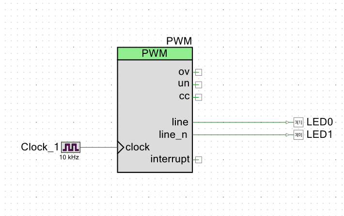
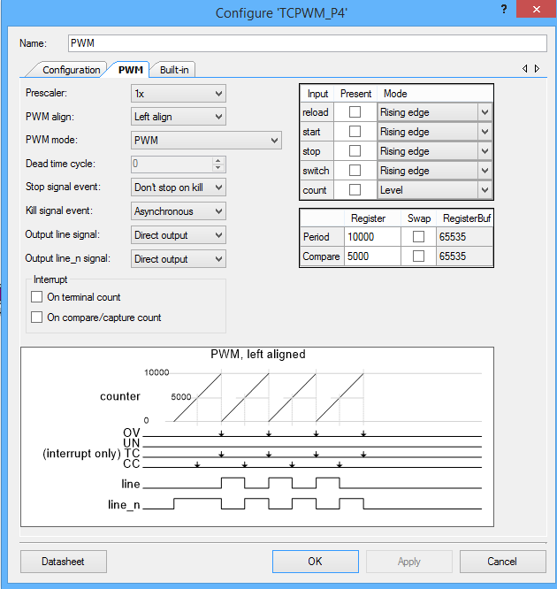
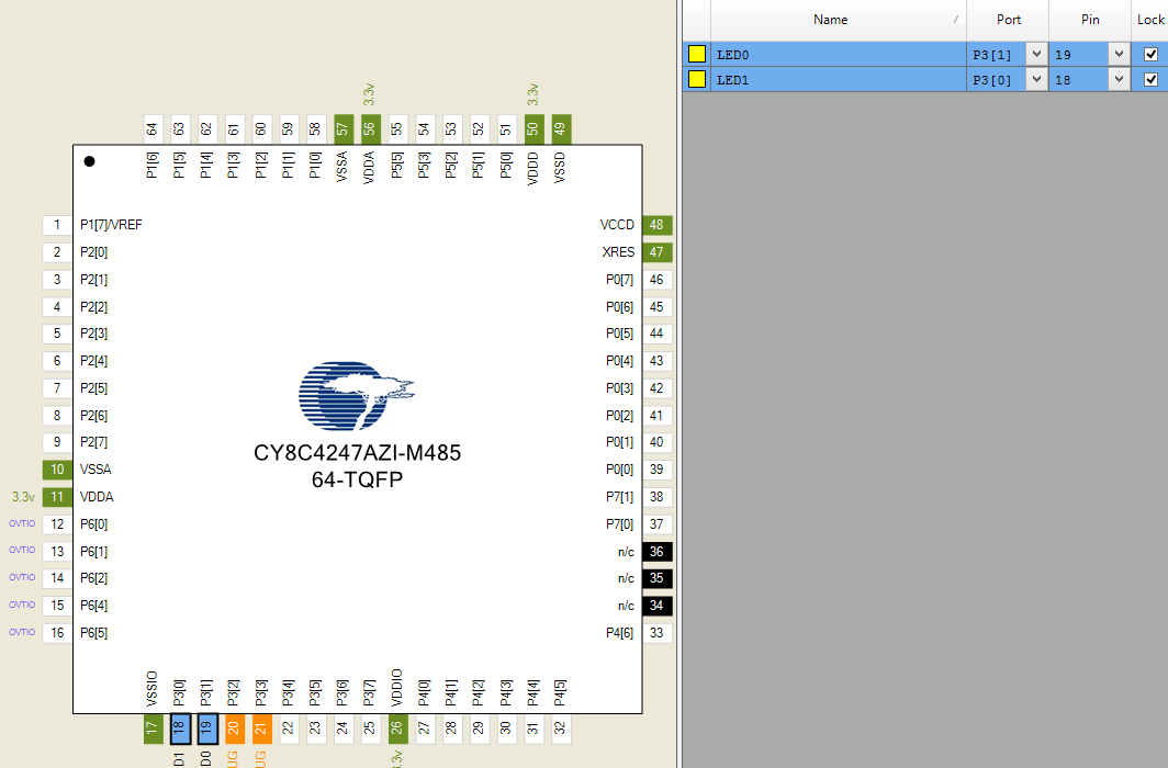
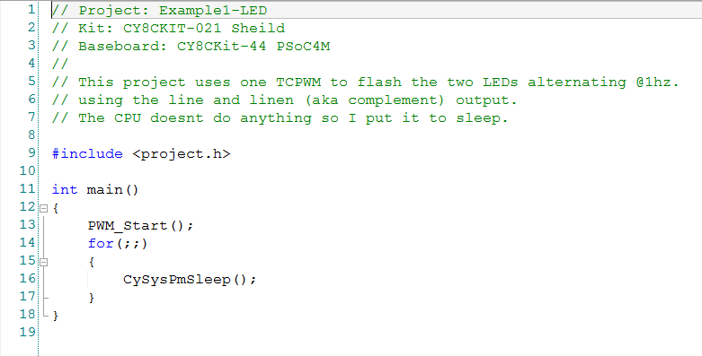
This weekend I taught people at the Bay Area Maker Faire to program PSoC. I told them that the first project that you always do is the blinking LED. This simple project is perfect to show that the tools work etc. So, that is what we will do here. For this example I used a TCPWM to blink the two LEDs. One LED is connected to the line output and the other one is connected to the line_n output. This will cause the LEDs to alternate. The only other slightly interesting thing that I do is put the CPU to sleep and just let the hardware do the blinking.
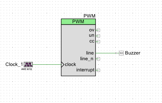
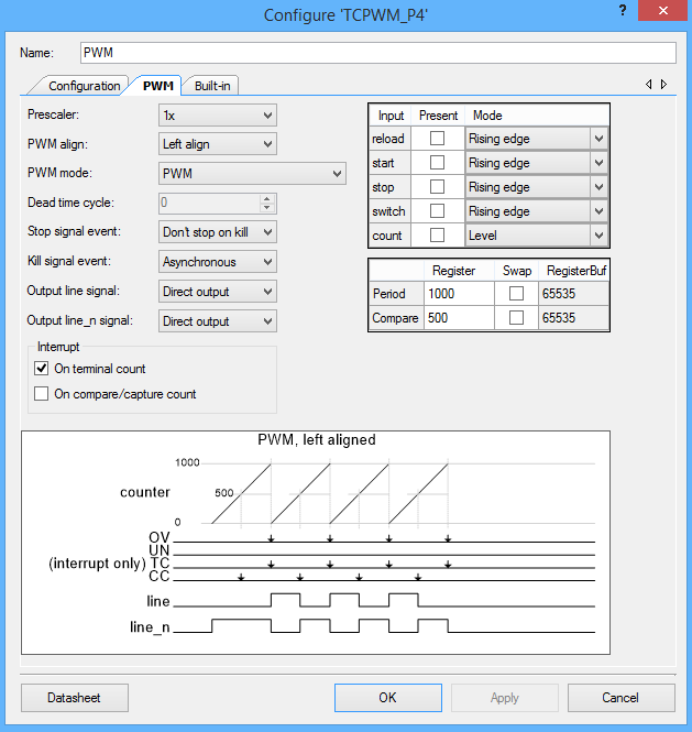
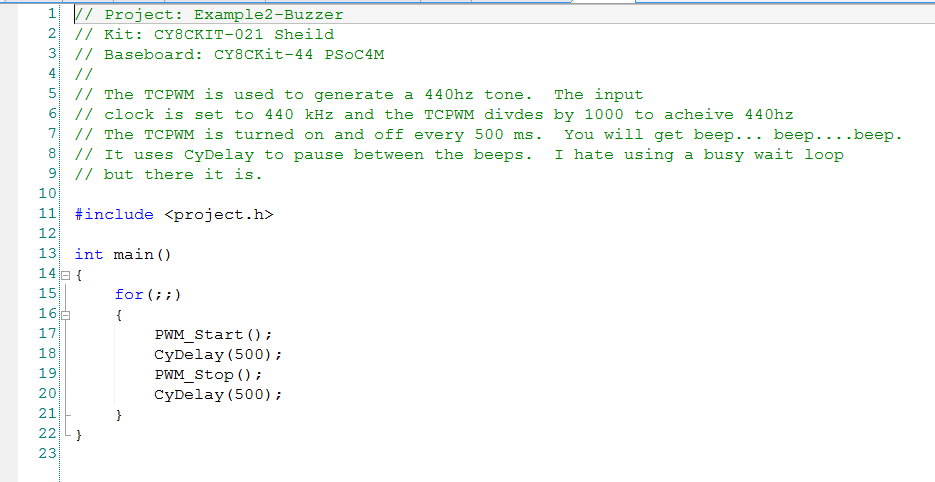
Example 2: A buzzer
To beep the buzzer I will use a 440hz tone that is generated by the TCPWM which divides an input clock of 440khz by 1000 to achieve the note “A” or “A4”. To make the tone turn on and off I do my most hated thing, use the CyDelay to make a busy wait loop. Basically, I turn on the PWM, wait for 500ms then turn it off, wait for 500ms and then go back to the start.
Example 3: Direct Drive 7 Segment LCD
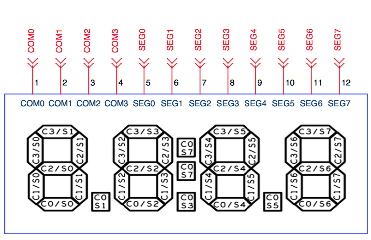
A very cool feature of almost all of the PSoCs is their ability to drive “direct drive LCDs”. This is a very low cost, low power way to add a display to your design. This display we used on this board is a Lumex LCD-S401M16KR that costs $0.73 from Mouser. Internally, all LCDs are organized into rows and columns a.k.a Segments and Commons. To enable a particular segment in the LCD you need to select the correct row and column. Then to make a symbol on the screen you need to select the combination of segments for that number. For example, from the picture below, to make a “7” on the left digit you would need to turn on C3/S1, C2/S1, and C1/S1. This would be a serious pain in the ass, but conveniently, the PSoC Creator segment LCD component does this for you automatically.
Our Lumex display is organized into 8 Segments and 4 Commons. This means that it takes 12 pins on the chip and can show 32 segments. The segments are organized into 4 characters with 7 segments (28 total segments), a decimal point between each character (3 segments) and a colon. Here is a picture:
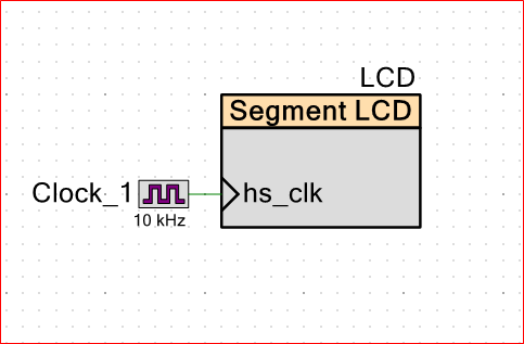
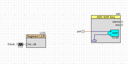
First add the segment LCD component to your design and attach a clock
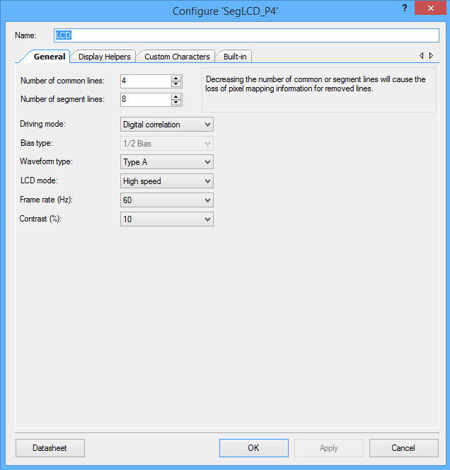
Then make the top level configuration (4 commons and 8 segments)
To configure the component display you need to first add a “7 segment” helper to your component by selecting it and then clicking the right arrow. Then you click the “+” 4 times to add 4 digits to your design. Then you need to drag and drop the each segment from the digits onto the correct location on the segment/common matrix in the “pixel mapping table”. For example “Common 3 / Segment 1” or “C3/S1” is the top segment in the left digit (look at the picture above), it needs to go in the “Com3” column and the “Seg1” row. There is a pattern and once you see it this will not take very long.
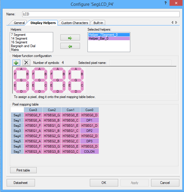
The next step is to add the decimal points and colons to your project. To do this add a “barograph and dial” helper. Then click the “+” 4 times so that you have 4 segments. As you add each one give it an appropriate name e.g. “colon” or “dp1”

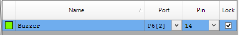
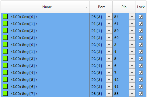
The last thing that you need to do is to assign the pins.
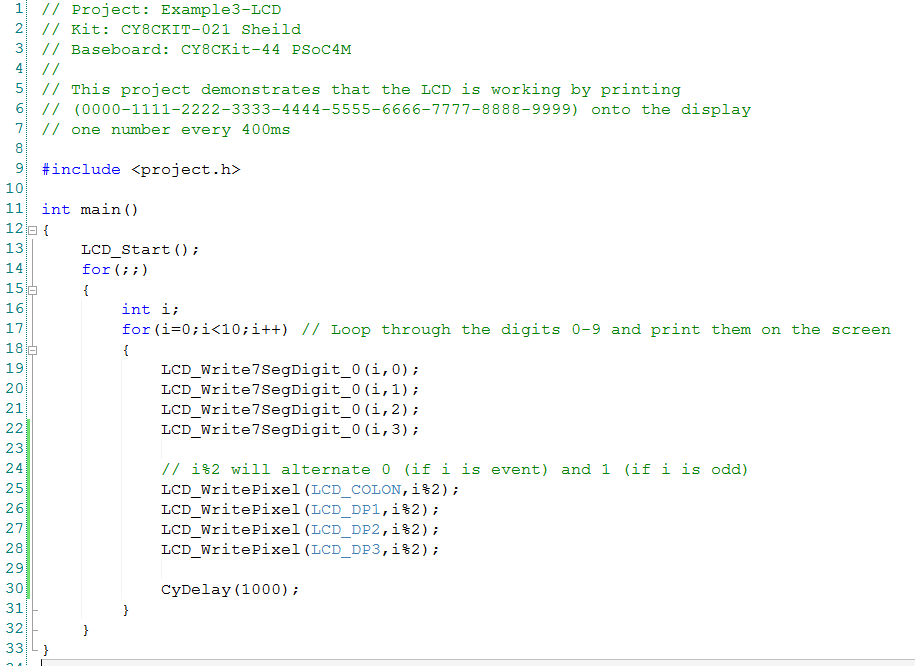
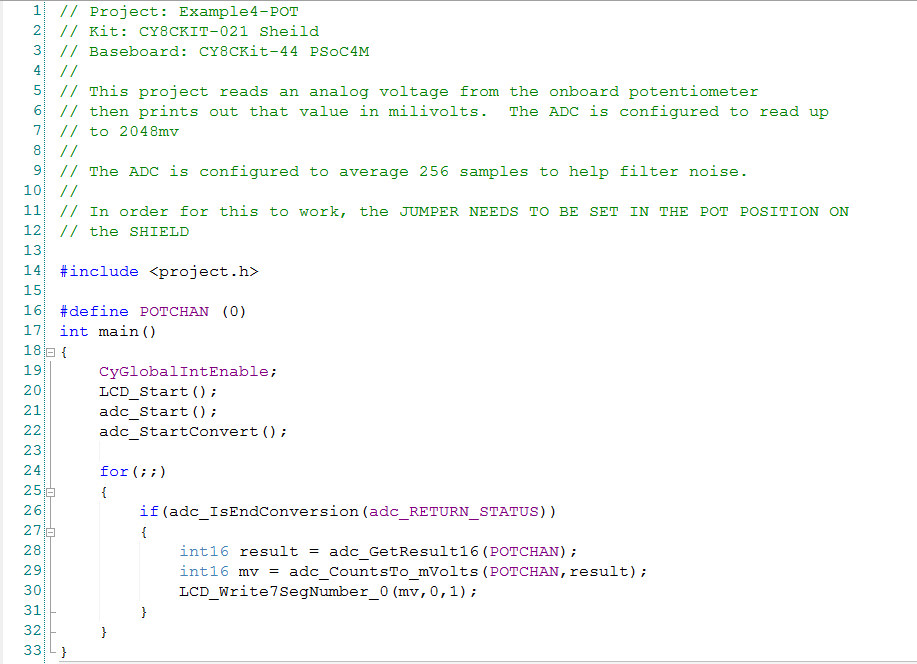
The firmware is simple:
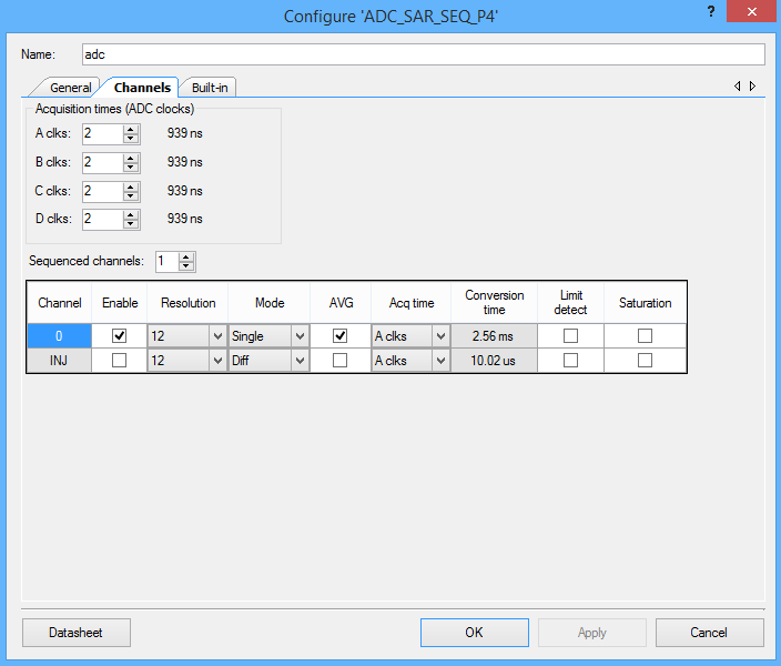
Example 4: The Potentiometer
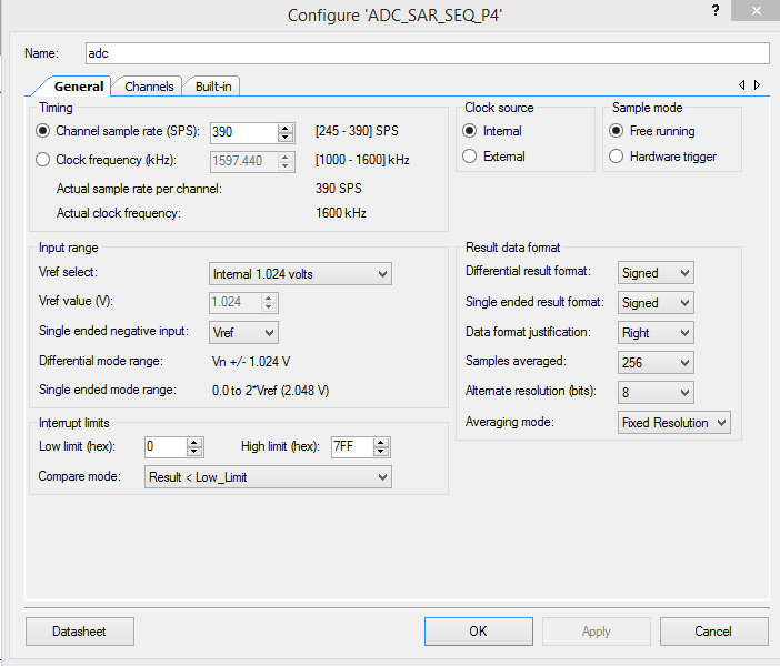
To test the potentiometer I will use the ADC to measure its output voltage and then display it on the LCD screen.
I am out of time… so in the next post Ill show examples 5,6,7
Alan
index
description
CY8CKIT-021: A Simple FM/PSoC + BLE Demonstration Board
Introduction to CY8CKIT021
CY8CKIT-021: The first four example projects
Use the LEDs
Buzzer
7-Segment display and the Potentiometer
CY8CKIT-021: The next three example projects
Use theThermistor and two Capsense Examples
CY8CKIT-021: Bootloading the PRoC
How to put firmware into the PRoC
CY8CKIT-021: The BLEIOT Component
A custom component to communicate with the PRoC/PSoC
CY8CKIT-021: Using the BLEIOT Component
A full example of the tho MCUs talking
CY8CKIT-021: The PRoC BLE Firmware
How to make PRoC Firmware and use it with the BLEIOT Component
CY8CKIT-021: Example 10 - the new IOS App
How to build and IOS App to talk to the development kit
No comment yet, add your voice below!