The PRoC (on the shield) and the baseboard share two pairs of lines that are connected to the Serial Communication Blocks (SCBs) on the chips. One of the pairs is also connected to the standard I2C Arduino bridge pins and in fact this is how you bootloaded the PRoC in the previous example. When I started thinking about the problem of making the PRoC on the shield talk to the baseboard I knew that I wanted either side to be able to initiate communication and I did not want either side to poll. This fact eliminated the master/slave scheme of I2C or SPI. OK. UART it is.
The next thing that I knew that I wanted was one set of firmware that would work exactly the same on both side. This lead me to build a component called BLEIOT. This component has the following features
- It transmits its local status every 20 ms
- It is triggered by the Systick
- It uses UART to transmit and receive
- It has a “Update” API which will update the local and remote state
- It has dirtyFlags which are a bit mask of what was written from the other side and is different than the current local status
- The component works the same on both sides
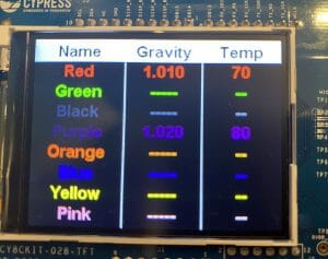
- It has a data structure that represents all of the peripherals on the shield (LEDs, Thermistor, CapSense Buttons etc)
The system works by having a “local” copy of the state and a last known “remote” copy of the state. There is a C-Structure that represents each of the system variables (LED, CapSense, …). The way it works is:
- When something changes in your system you use the “Update” API.
- The update API changes the local state and the “Write Flags” which is just a bit mask of all of the local variables
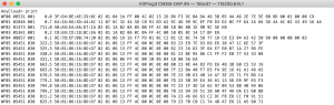
- Every 20ms the component sends the local table to the remote side (assuming something has been written)
- The remote side then looks at each variable that has been “written” and compares it against the local copy. If they are different then it marks the “dirtyFlags” with the corresponding bitmask
- On either side you can monitor the “dirtyFlags”. If the dirtyFlag for a variable is set then you know that the other side changed it and you can do something.
- When you run the “Update” API if you write your local copy to be the same as the remote copy then you will clear the dirtyFlag.
This project is available as BLEInterface in the CY8CKIT-021 workspace that is in the firmware directory on github at github.com/iotexpert/CY8CKIT-021
Here is a picture of the architecture:

An example:
- Everything starts in sync
- The PSoC turns on an LED with Pin_Write()
- The PSoC calls the BLEIOT_updateLed API
- That BLEIOT_updateLed API updates the local state table
- That BLEIOT_updateLed API marks the “writeFlag” corresponding to the LED
- The PSoC systick triggers the BLEIOT component to send the local table to the PRoC via UART
- The PRoC UART receives the table and calls the BLEIOT_receive API
- The PRoC BLEIOT component looks at the “Write Flags” and notices that the LED was written, so it marks the dirtyFlag corresponding to the LED
- The PRoC main loop notices the dirtyFlag and turns on the LED using Pin_Write
- The PRoC then runs the BLEIOT_updateLed function which updates the local state and clears the dirtyFlag
- The PRoC systick calls the BLEIOT_send which sends the local state table to the PSoC
- The PSoC calls the BLEIOT_receive
- The PSoC BLEIOT_receive notices that the LED was written but that its remote state now matches its local state so it doesn’t do anything
Building the Component
In order to make a component this component I need
- A symbol for the component
- A schematic (with the UART)
- The BLEIOT.h (which is the public interface to the component)
- The BLEIOT.c (which hold the functions that makeup the component)
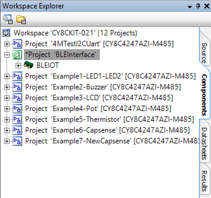
To make the component I start by adding a “library project” to my workspace called BleInterface. You do this from the new project dialog.
Then I click on the components tab of the BleInterface project. This is a bit of a trick as it seems like the library is “empty” but it isn’t.
The next step is to create a symbol by right clicking the library and saying “add component item” and choosing Symbol Wizard. If you are doing this make sure that you give the component a good name (or at least something better than “component01”
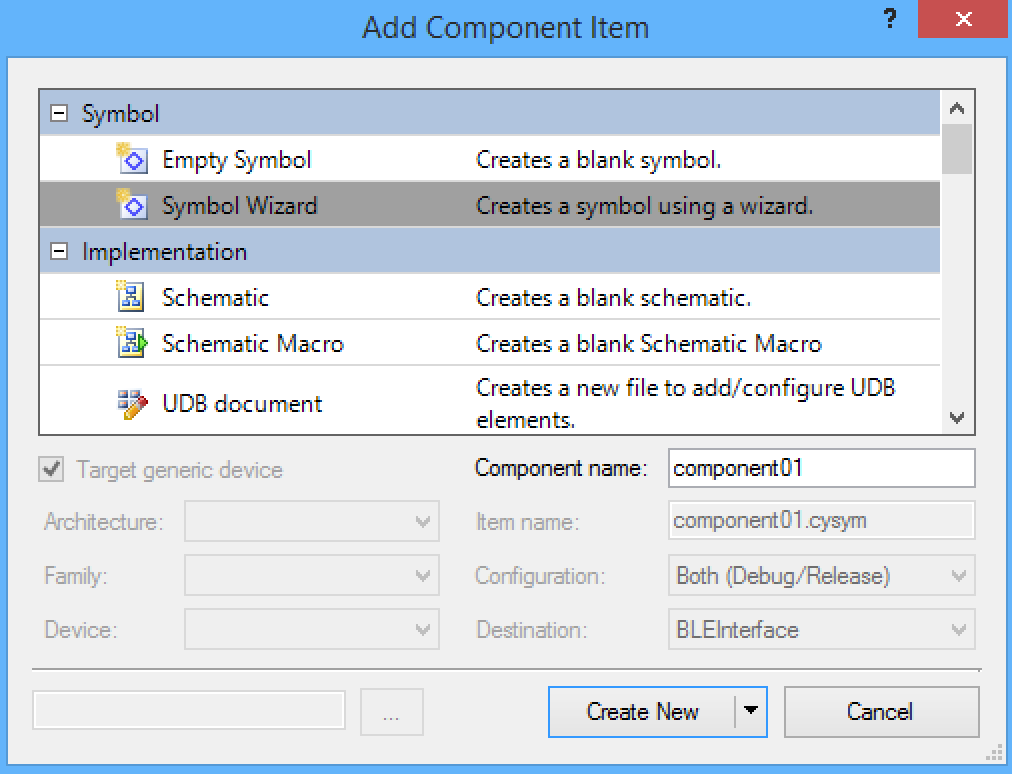
This component does not have any visible terminals so just accept the defaults.
In the next step I create a schematic to hold the UART component. When you add the component item for the schematic you need to configure the architecture to target the PSoC4 family in order to have access to place the SCB UART. After you have placed the UART component you will automatically get “buried” pins which you can assign for that component.
Now that I have a schematic and a symbol, the last steps are to add the .h and .c
The .h contains the public interface to the component.
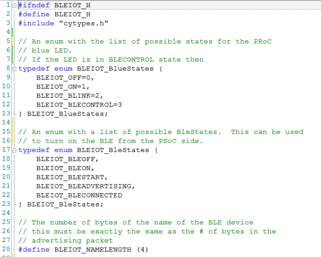
This section defines the public interface. On update function per system state.
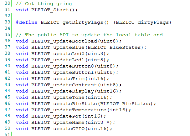
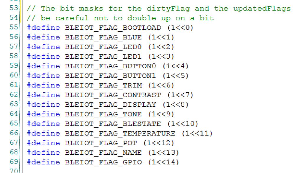
The bit masks for the dirtyFlags and updatedFlags
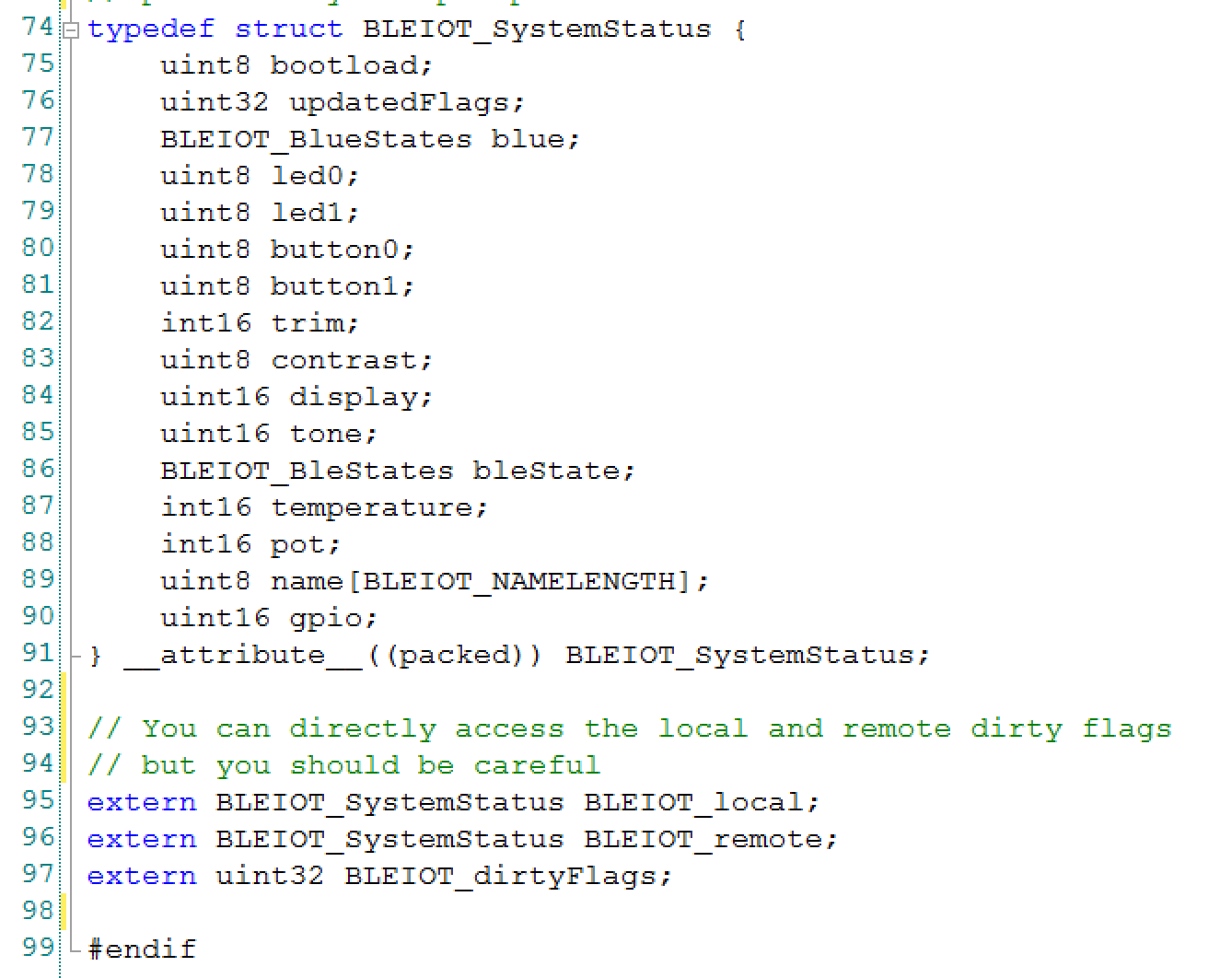
The definition of the table of variables.
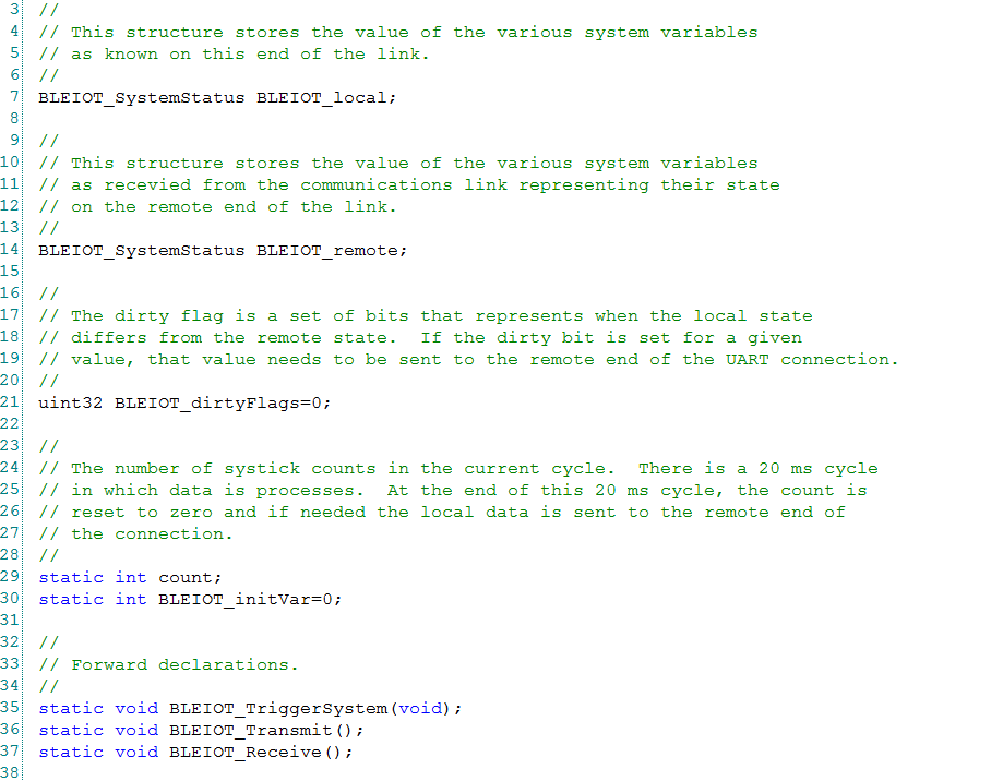
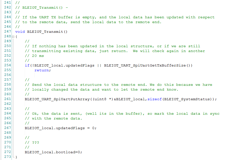
The last thing that you need is “BLEIOT.c”
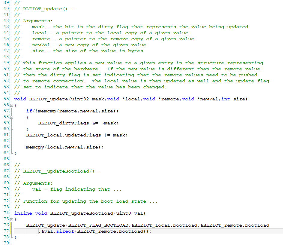
The update function is a generic function that will “update” the local table with the current value of one of the local status (LED0, CapSense …). This function is called by the various helper function (updateLed0, updateBootload, updateCapsense,…)
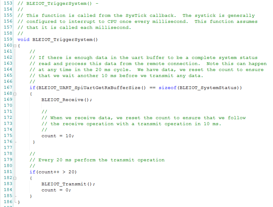
This function sends the data to the other side when it gets a turn from the systick interrupt
In the next post Ill show you an example project of the BLEIOT.
index
description
CY8CKIT-021: A Simple FM/PSoC + BLE Demonstration Board
Introduction to CY8CKIT021
CY8CKIT-021: The first four example projects
Use the LEDs
Buzzer
7-Segment display and the Potentiometer
CY8CKIT-021: The next three example projects
Use theThermistor and two Capsense Examples
CY8CKIT-021: Bootloading the PRoC
How to put firmware into the PRoC
CY8CKIT-021: The BLEIOT Component
A custom component to communicate with the PRoC/PSoC
CY8CKIT-021: Using the BLEIOT Component
A full example of the tho MCUs talking
CY8CKIT-021: The PRoC BLE Firmware
How to make PRoC Firmware and use it with the BLEIOT Component
CY8CKIT-021: Example 10 - the new IOS App
How to build and IOS App to talk to the development kit
No comment yet, add your voice below!