Pinball: OLED Display

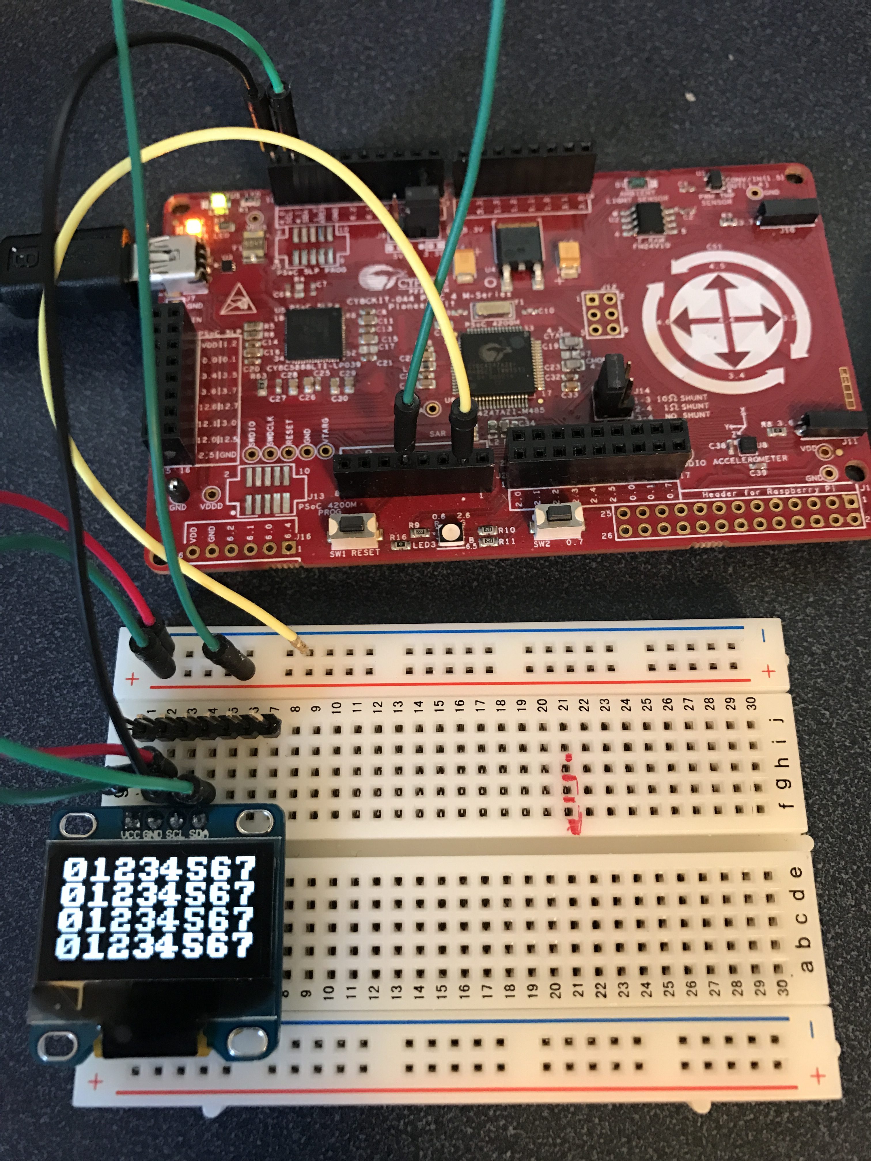
I screwed up the Pinball board design AGAIN!!!  It is so frustrating.  Ill write about the new design soon (and punish myself for the error.) As I worked on redoing the design I decided to put a footprint on the PCB for a small OLED LCD.   The display has an I2C interface, is about an inch wide and has 128×64 pixels… But, best of all can be purchased on eBay from China for about $3.00.  Here is a picture of the display with a PSoC4M driving it:

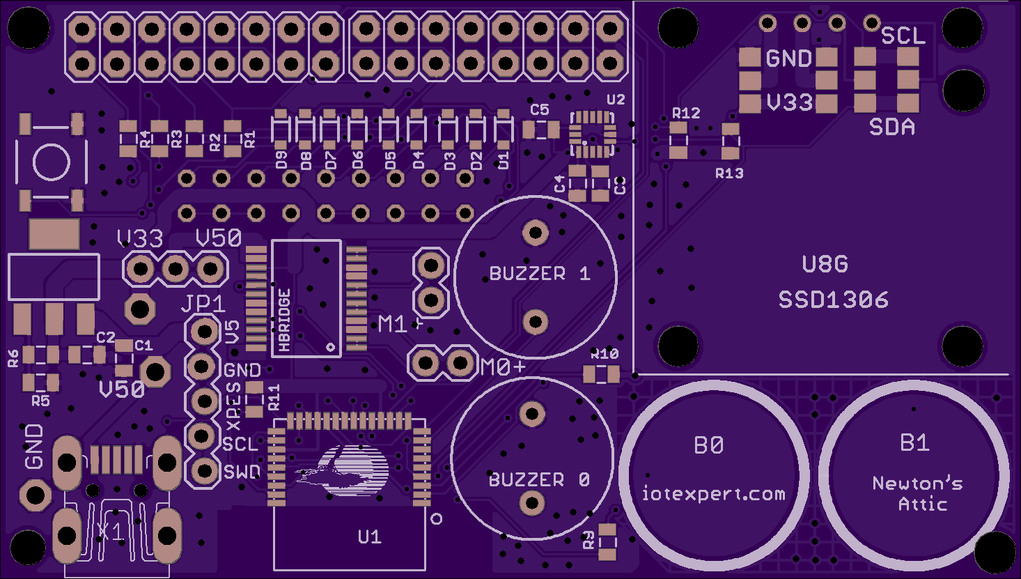
The display will go on the right side of the board.  Here is a rendering of the new board from the OSH Parks website:

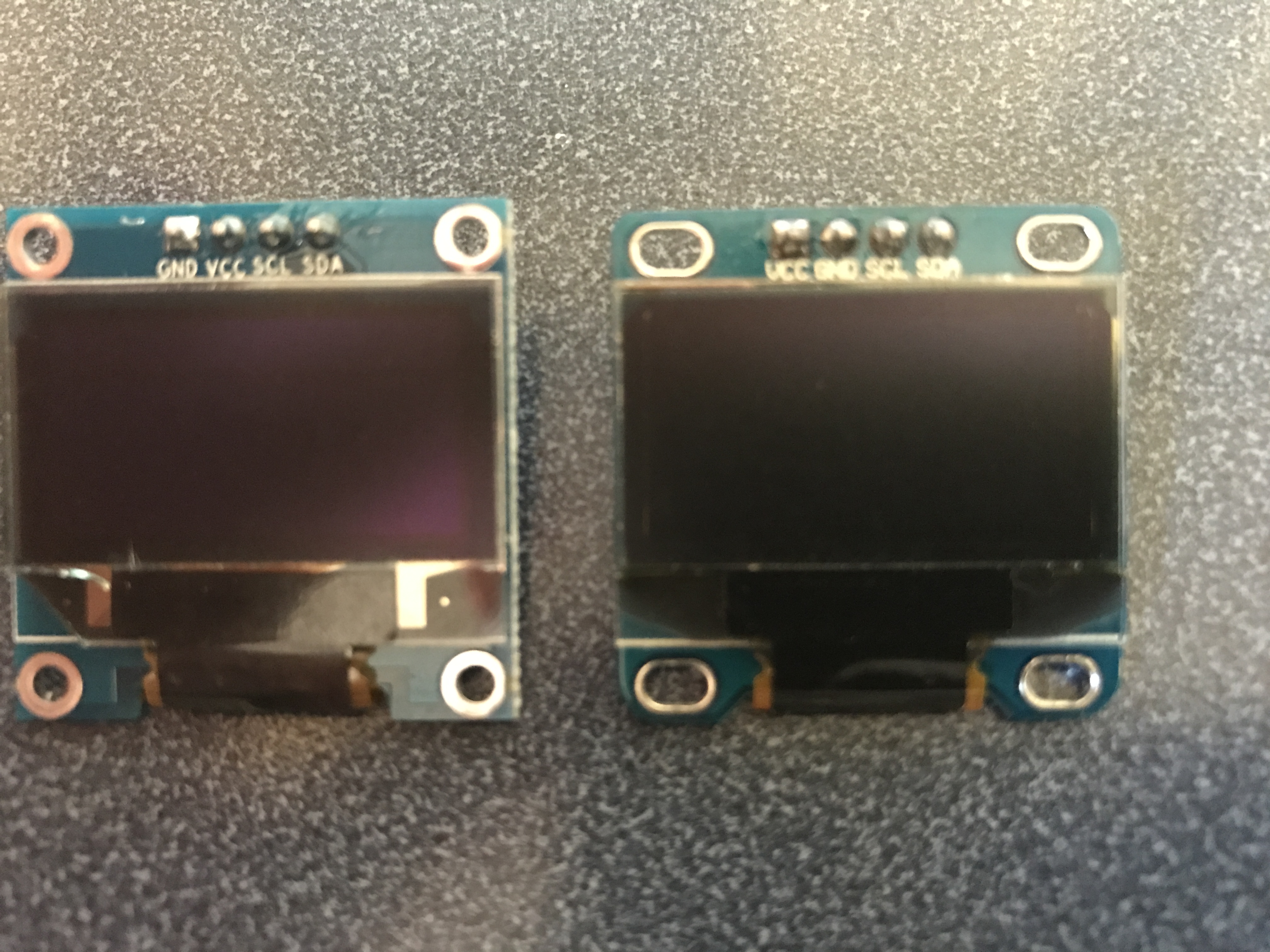
After I decided to put the footprint on the board I bought several displays from Amazon to try out, and to make sure that I knew how to make them work.  I immediately ran into some drama which caused me an evening of frustration.  If you look at the picture closely you can see that the power and ground pins are swapped:

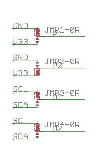
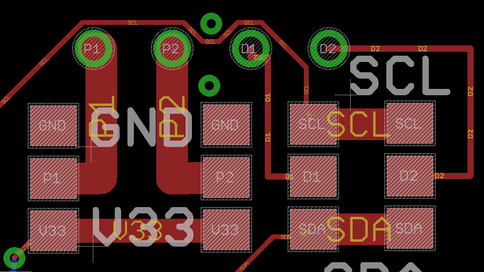
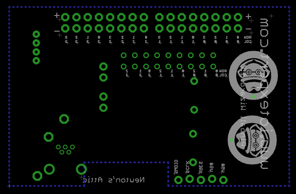
After I realized that was going to be a potential problem I put in a set of 0 ohm resistors on the upper right hand part of the board so that I could swap power/ground and scl/sda connections.  Here is a snapshot of the schematic and layout:

This left me with what software to use to drive the display which I will address in the next post.


Eagle PCB Layout Guidelines + OSH Park

Summary of Eagle PCB Layout Guidelines

I typically design my PCB’s in Eagle and have them manufactured at OSH Park.  Each new PCB layout feels like I am starting nearly from scratch because I only do about 1 or 2 boards per year.  Every time, as I go through the process, I promise myself that I am going to write down the list of things that I always need to relearn.  But, I never seem to get the list written down.  Today things change.  Here is my list:

  1. Make sure that you can actually purchase the components you put in your design
  2. No Airwires
  3. Vias tented (or not)
  4. Ideally no more than 2 vias on a net
  5. Power nets > 40mil
  6. Auto router setup
  7. Fill on the ground plane
  8. Ground fill around CapSense Widgets
  9. Test points on key nets – at very least power and ground
  10. Silkscreen font size
  11. Silkscreen labels on key nets
  12. Silkscreen key information onto the board
  13. Put in power supply jumper
  14. If there is I2C then put in a blank header to connect a mini-prog-3
  15. Extend the QFN footprints enough to be able to rework them
  16. Try not to route under QFNs
  17. Try not to use QFN with 0.5mm pitch
  18. Use the eye tool to compare every net in the schematic and layout
  19. DRC
  20. ERC
  21. CAM Job
  22. Don’t forget about the stencil

Make sure that you can actually purchase the components you put in your design

I used a footprint I found on the internet assuming that there was good availability for it.  But, I ended up having to order some weird USB connectors from a salvage shop in Poland.  I guess that I felt lucky to have been able to find them at all.  Unfortunately, I did the whole board and sent it to the shop before I was sure that I could buy everything.  Always always check to make sure you can purchase the device you place on the board.

No Airwires (seems like it would be obvious… but)

Airwires show the connectivity that is drawn in the schematic.  Unfortunately they don’t conduct electricity.  Until a REAL connection is made you will have a yellow flight line connecting between the pins in your layout.  Before you tapeout the board you MUST MUST press the Ratsnest button and get the message “Ratsnest: Nothing to do!”
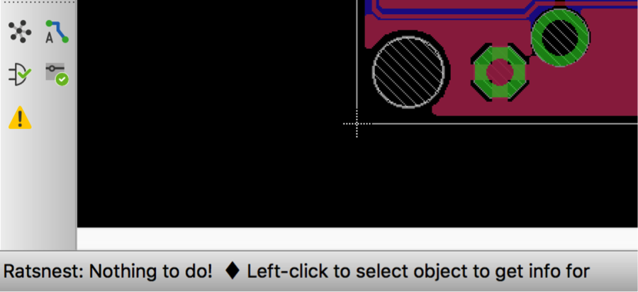
Eagle PCB message when all connections are made i.e. no airwires exist

If you do this:

An example of an air wire that will make you Eagle PCB not be connected.

Then you will need this:

An example in Eagle PCB of what happens if you leave an airwire unconnected

Vias tented (or not)

A tented via or a plugged via is a connection between the top and bottom of the printed circuit board that is covered with solder mask.  In general there are probably enough vias on your board that if you don’t cover them you will not be able to see the silkscreen (either because it won’t print on copper or because the PCB vendor will trim it).  Here is a picture of one of the versions of Physics Lab where I forgot to tent the vias.  In the upper left where it says “Elkhorn Creek Engineering” you can see that the “l” in Elkhorn and the “g” in Engineering is partially missing where there is a via in the board.
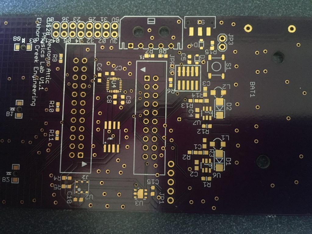
An example of an Eagle PCB with untented vias.  This board was made at OSHPark

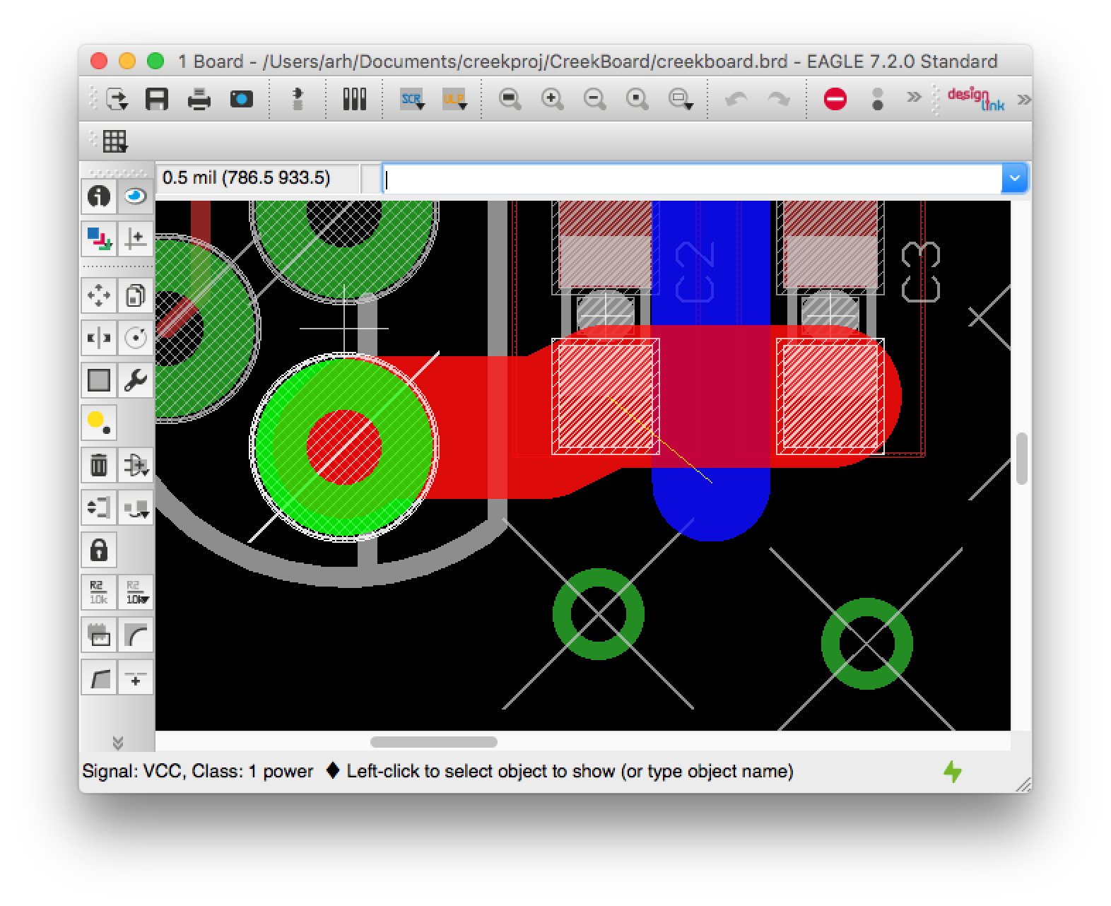
In Eagle PCB, Vias (and Pads) are automatically covered with the “tStop” mask.  Here is a screen shot of a PCB that I am working on with just the “Pads”, “Vias” and “tStop” layers shown.  You can see the “big” holes which are Pads for through-hole components.  You can see that they have the diagonal white lines through them that represents the “tStop” mask.  tStop is the mask that prevents the solder mask from being applied.  In the picture you can also see the tStop on places where there are SMD pads.  And, you can see a bunch of the smaller vias which are not covered.
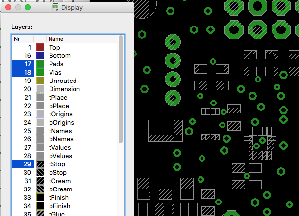
An example of an Eagle PCB with via and stop mask turned on.

To tell Eagle PCB to turn off the tStop for vias you need to change the design rules on the “Tools->DRC->Masks” screen.  The limit parameter tells Eagle PCB to NOT create “tStop” for any via/pad that is less than 30mil in diameter.
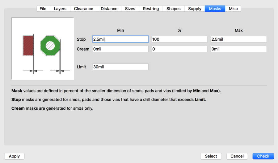
Eagle PCB DRC rules screen where tented vias are specified.

No more than 2 vias on a net

I always strive to keep all of the nets on my two layer print circuit boards to have no more than 2 vias.   To look for this I click on the “eye” tool to probe each net of the layout, then I manually trace the net.  Here is a screen shot of a net that I try to avoid.  You can see that the net starts on the SMD pad in the lower right, then winds its way to the top left.  It goes through 4 vias.  Unfortunately it goes through one more via before reaching the SMD pad just below the upper left.
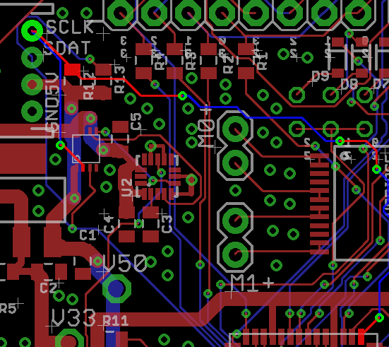
An example of proving a network using the Eagle PCB eye tool to look for more than 2 vias on a net.

Power nets > 40mil

I like the power and ground nets to be routed in at least 40mil wires.  To do this, you first need to create another net class in the “Edit–>Net classes” menu.  I always create a class called “power”.  Then I set the minimum width to 40mil.  If for some reason you want to have a minimum clearance or drill you can set this here as well.  If you leave it at 0,  Eagle PCB will use the default rules.
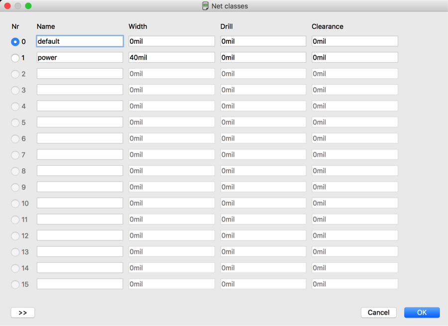
How to specify 40mil spacing on a power net in Eagle PCB.

After you have created the power net class, you then need to assign the correct nets to the net class.  You do this in the schematic by selecting the “I” tool, then clicking on the net.  Then you can select the “Net Class” for that net.  In this case I am editing the V50 net.
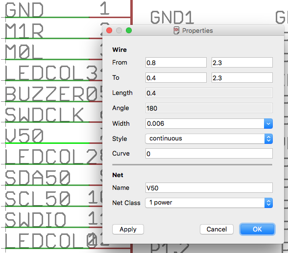
How to attach a signal to a specific net class in Eagle PCB.

Auto Router Setup

I am absolutely terrible at designing PCBs.  This frustrates me to no end.  One of the crutches that I like to use the the Eagle PCB Autorouter.  The only change that I currently make is to use the “*” option to let the router go whatever direction it thinks that it should.
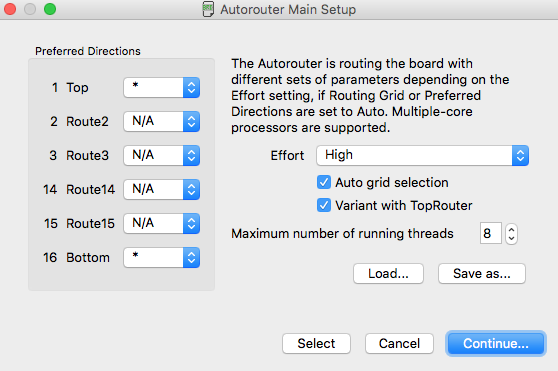
Configuring the Eagle PCB Auto Router.

Fill on the ground plane

To create a ground plan you need to:

  • Draw a “polygon” around your board in the “top and bottom” layers.
  • Attach those polygons to the correct net e.g. “gnd” by typing the “name” command and then clicking on the ground polygon

When you press the “ratsnest” button Eagle will fill the ground plane.
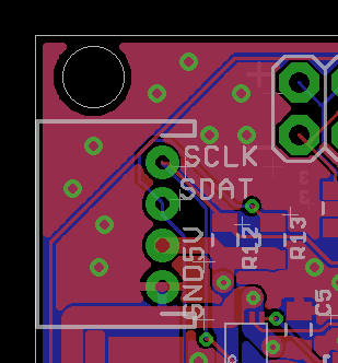
An example of the ground plan pour in Eagle PCB.

If you want it to unpour it you can run “ripup @;”.  When the ground plane is not filled it will appear as a dotted line around the board:
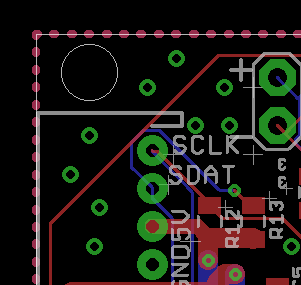
Eagle PCB ground plane pour example

To attach the top and the bottom ground planes together you need to put a via on the correct net.  To do this:

  • Click on the “via”
  • Click where you want it to attach the top and bottom
  • Add to the the right net using the “name” command and then typing the signal name
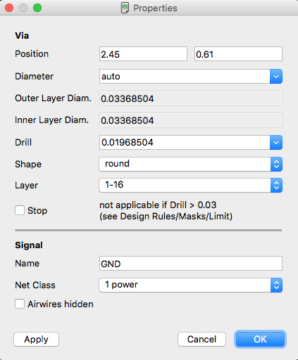
How to attach a polygon to the ground plan in Eagle PCB.

Ground Fill Around CapSense Widgets

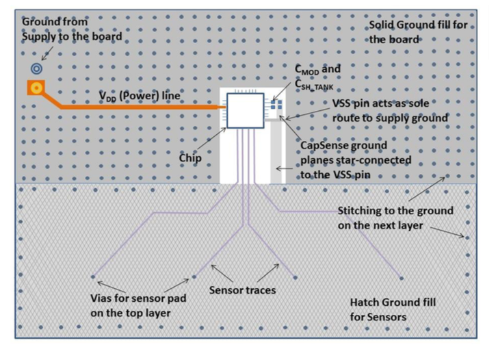
In order to get the best CapSense performance you want to have a “hatched” ground plane surrounding your widgets.  The methods for doing this are documented in the CapSense Design Guideline Section 6.4.9 “Ground Plane”.  Here is an idealized view of the back of the front and back of the board:
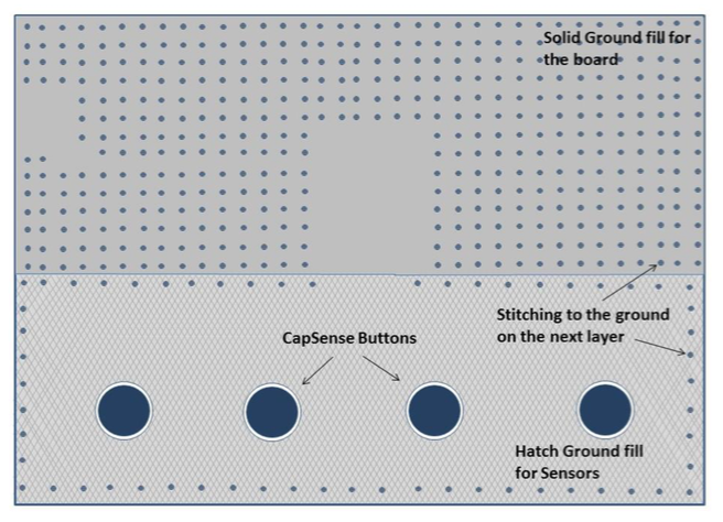
PSoC CapSense ground plane

PSoC CapSense ground plane example

The guidelines go on to recommend that you use 25% (7 width 45 spacing) coverage on the top and 17% (7 width 70 spacing) on the back.  To do this in Eagle PCB you draw a normal polygon on the top and bottom.  Then you use the name command to give it the “ground” name.  Then you click the “i” to set the parameters.

  • Set the width to 7 (mil)
  • Set the polygon pour to “hatch”
  • Set the Spacing to 52 (mil).  The only trick is that the Eagle PCB spacing isn’t actually the spacing between the lines but the Pitch between the hatched cells.  So to achieve 45 mil spacing with a 7mil line you need 45+7=52 “spacing”
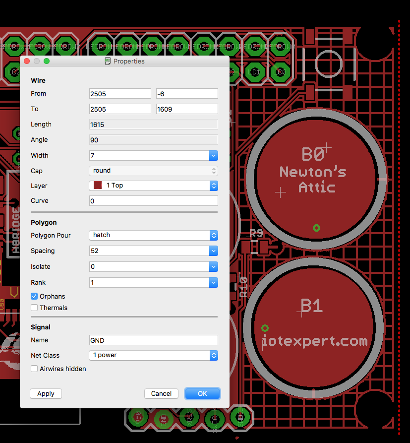
Specifying the ground plane pour for a PSoC Capsense in Eagle PCB

Test points on key nets – at very least power and ground

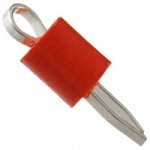
It is a serious PITA to debug a board if there is no place to attach test leads.  I like to use a looped wire that you can install onto the board through a PAD.  Here is a red one that I use on power nets that I bought from digikey.com
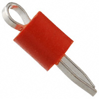
PCB Probe Point

Silkscreen Font Size (don’t go less than 30mil@15%)

I believe that the best practice for your silkscreen fonts is to first tell Eagle PCB to use “Always vector font” on the “Options–>User Interface” menu.  This will make what you see on the board much closer to what you see on the screen.
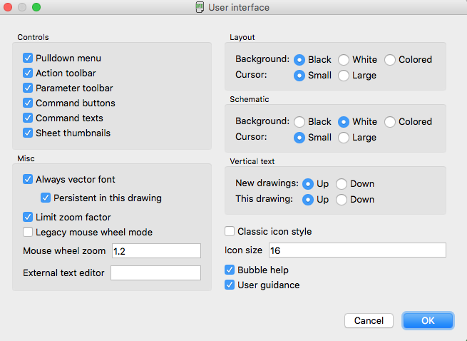
Eagle PCB Vector Font

There are two issues with font size.

  • First, what can you see (Im 48… so my fine vision is going away) so I think 30mil is the absolute minimum.  40mil or 50mil is even better.
  • Second, what your PCB design house can print (about 5mil at OSH Park)

I am having my current PCB made at www.oshpark.com.  I could not find their silkscreen spec on their website… but an OSH Park Person “tweeted” that they can print 5mil silkscreen.

Given all of that.  Your best bet is to use a “vector font”.  When you select a vector font, you specify how tall the characters are, and how thick the lines are as a % of the height.  Here is a screenshot of my “SDAT” label.
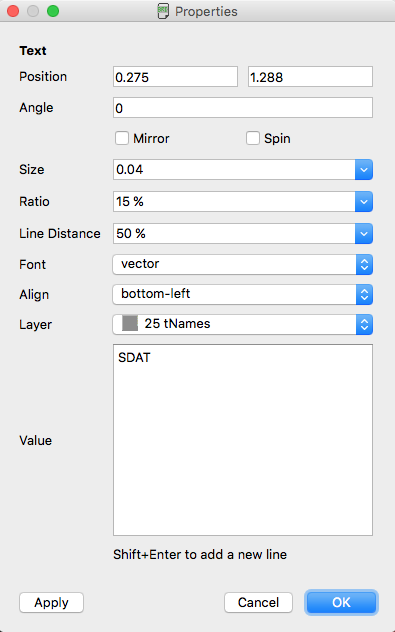
Creating a silkscreen in Eagle PCB

I made this table of what I think is a safe range:

Eagle PCB Font Size Guidelines

On the the lukemiller.org blog I found a picture of an OSH park board with some different vector combinations:
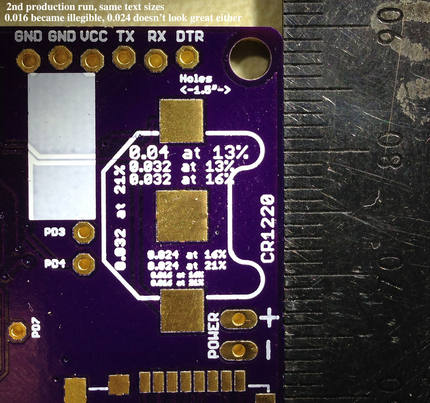
Example PCB Font Sizes

On the justgeek.de blog I found another board:

Example PCB Font Sizes

Silkscreen on key nets

You should make sure and label every pin that you would need to interact with or debug.  For example, the board below has a place to plug in a miniprog-3 in 5-pin mode:  The connection is directional so labeling the pins is key: [Note: A friend of mine noticed that I labeled the MiniProg-3 connection INCORRECTLY!!!! notice that there are two V50 (when in reality the inboard one is supposed to be ground]
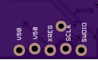
Example of an error in an Eagle PCB Silkscreen

Don’t forget about the back of the board.  If you don’t put labels on the back, you will endup trying to figure out what the holes are (like the ones in the lower right) by flipping the board back and forth.
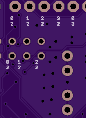
Example of Eagle PCB Silkscreen

Silkscreen key information onto the board

You should definitely “comment” your board on the silkscreen with at very least:

  • Name of the board
  • Version number of the board
  • Name of the maker e.g. www.iotexpert.com

Key information on Eagle PCB Silkscreen

Put on Power Jumper

You should also put in a 2x100mil spaced jumpers with a 0 ohm resistor shorting them in the path of the power so that you can measure the power supply current.

If there is I2C then put in a blank header to connect a mini-prog-3

If you have an I2C bus in your design, and you have room on the board, you should provide a place to plug in the 5-pin mini-prog3 to help you debug.  This will let you interact with chips on the bus without having completed the firmware for the central MCU.
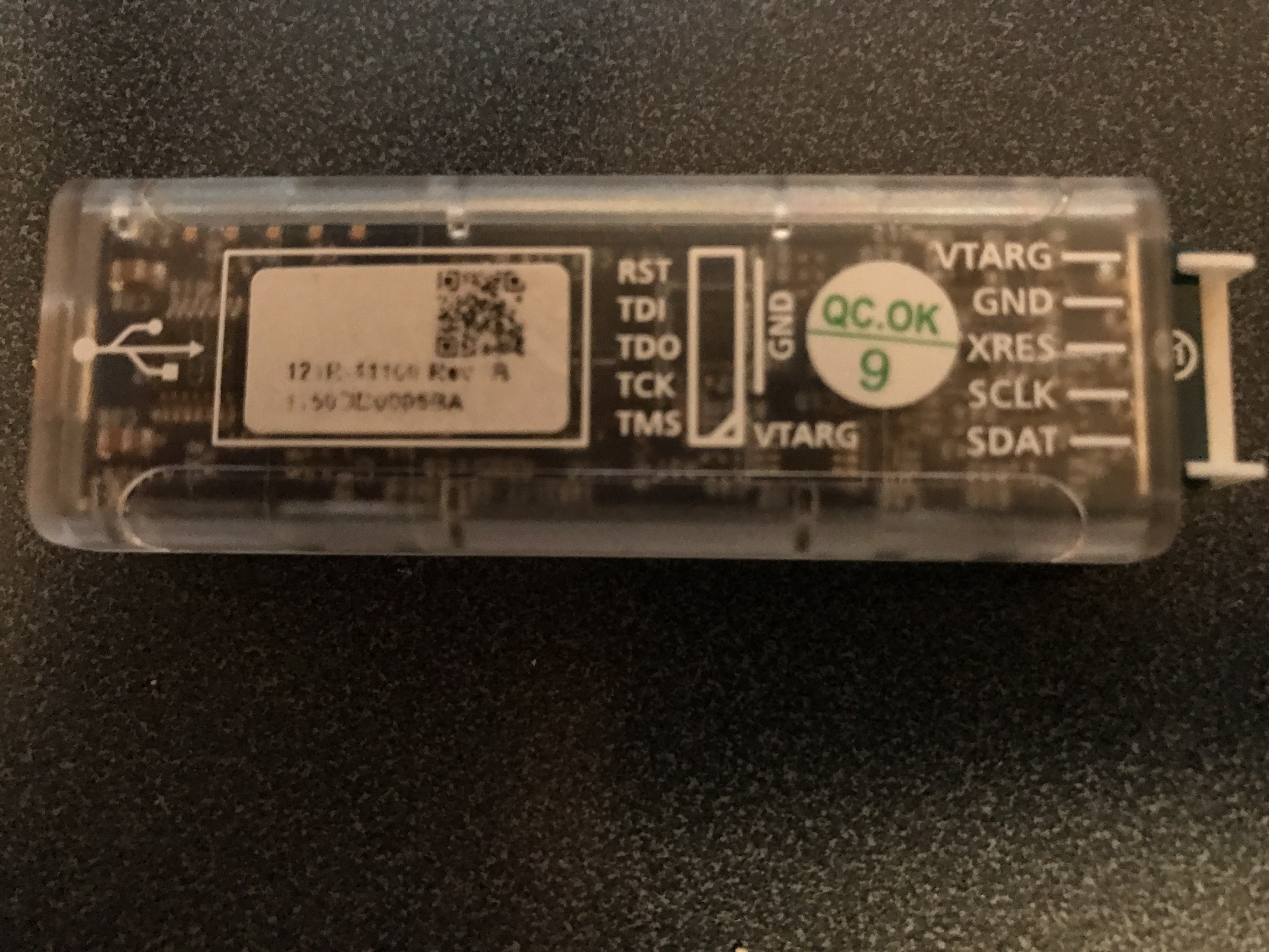
Cypress Miniprog-3

Extend the QFN footprints enough to be able to rework them

If you extend the edge of a QFN pad by 0.3mm past the edge of the chip, you will have some chance to be able to see that the original reflow worked (or didn’t).  In addition you will give yourself a small chance to be able to rework it with a soldering iron.  For example in the picture below you can see the pin one in from the left has no solder on it.  I was able to successfully rework this pin with a soldering iron.
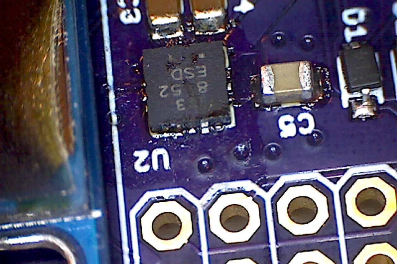
Eagle PCB QFN Footprint

Try not to route under QFNs

If you have all solder mask under your QFNs it will be much easier to do the original reflow as it will push solder out from under the chip.  On tiny pitch QFNs if you have routing you may end up with a messy blob of solder.  Here is an example of what not to do.
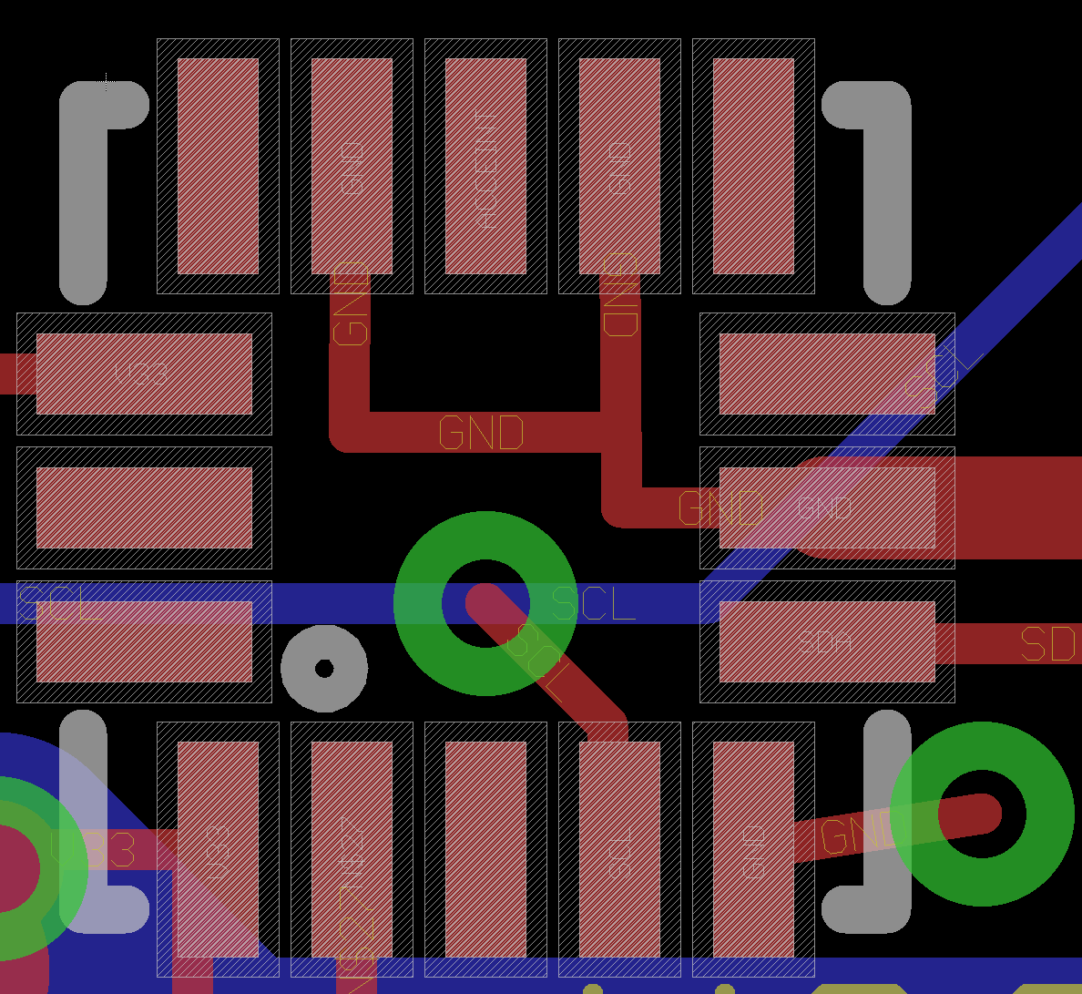
Example Eagle PCB QFN Footprint

Try not to use QFN with 0.5mm pitch

Try to use 0.65mm pitch QFNs as they are much easier to reflow.  If you use 0.5mm pitch QFNs you are going to struggle to get them correct.  If you use a pitch less than 0.5mm then good luck to you.

Use the eye tool to compare the schematic and layout

I always open up the schematic and layout in side by side windows.  Then I click on each device in the schematic and look at the results in the layout.  In the picture below I clicked on “SWCOL2”.  This is called cross probing.  You should look at each net one by one to make sure that nothing funky happened.
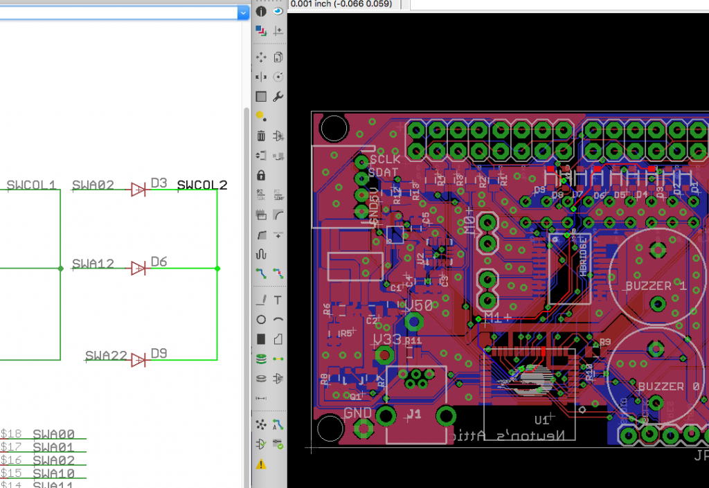
Eagle PCB Eye Tool for net cross probing

DRC

The Design Rule Checker (DRC) in Eagle PCB works pretty well.  USE IT.  You can get a rules file from OSH Park (for their two layer process) from their website

You can also use the freedfm.com website to check your files.

Two things that you should be aware of when you run your final DRC.

  1. If you setup a special rule for the power net-clasesses that is greater than the minimum rule you may want to turn it back to the minimum when you run the final DRC.  For example, when I setup the ground layer as a power layer, I set the minimum rule to be 40.  Before I run the final DRC I set it back to 6.
  2. For any polygon that is setup as a pour, you will need to set the minimum width of that polygon to be the same as the minimum for the layer.  For example: the minimum top metal width at OSH park is 6mil.  This means you need to set the minimum width of the ground pour to be 6mil.  Here is a screenshot of the corner of the board:
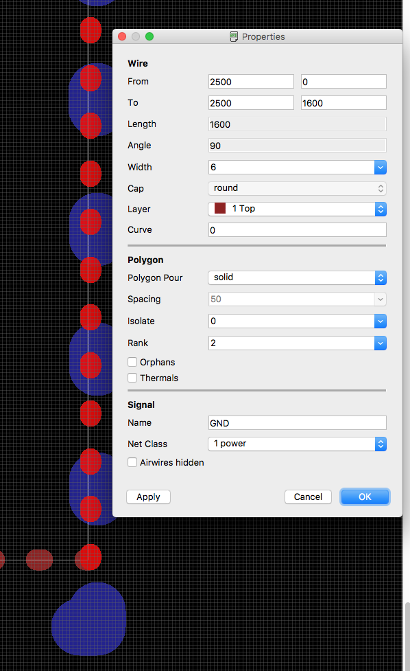
Eagle PCB DRC

ERC

The Eagle Electrical Rule Checker (ERC) typically catches some problems.  By far my biggest problem with the schematics in Eagle is that I occasionally make two wires “connect” by touching, but Eagle doesn’t think that they are connected.  The ERC seems to catch this problem pretty well.  You should at least run it and go through the errors to make sure that they are false.

CAM Job

In order for OSH Park to make your PCB you need to make Gerber files.  Actually, OSH Park can do that for you, but I recommend you do it for yourself so that you are sure what is going to get made.  Gerber files are the lingua franca of the PCB business.  One file contains one layer for manufacturing, so you will need one file for each layer.

To do maker the Gerbers you need to run the “CAM Processor” which can be found on the tools menu.  I reccomend that you start with a preexisting CAM job (like the one that you can download from OSH Park)

The CAM job will have one “tab” for each layer that it creates.  In the picture below you can see that I am making the Top Silkscreen.  That layer is created by combining “tPlace” and “tNames” onto one layer and then writing it to the file “…/…/…/gerber/.GTO” in the GERBER_RS274X format.
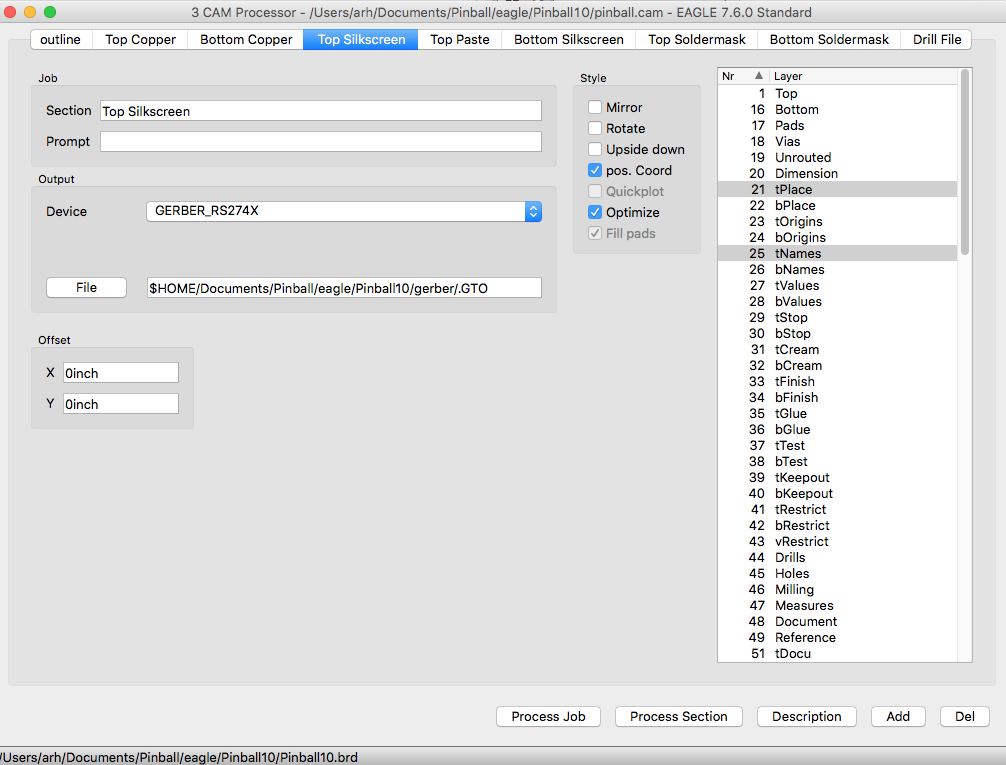
Eagle PCB CAM Job Configuration

The file naming convention is:

File Extension Description
.GTO Top silkscreen
.GTL Top copper
.GBL Bottom copper
.GTP Top Paste (aka the solder paste layer.. you make the solder stencil from this layer)
.GBO Bottom silkscreen
.GTS Top Solder Mask
.GBS Bottom Solder Mask
.TXT Drill file – used for CNC mill that drills the holes in your board.. this is not a Gerber file

After you have the Gerber files you can look at them in gerbv which is an open source tool.
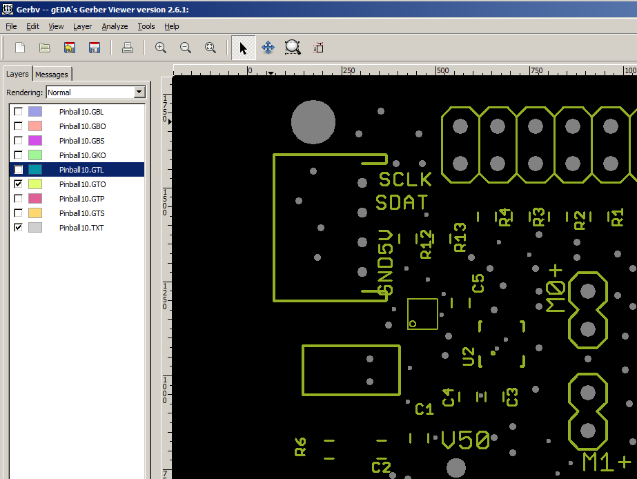
Gerbv Gerber Viewer

Stencils

Lastly, don’t forget your stencil.  I buy mine from www.oshstencils.com which is linked to www.oshpark.com, so you can just select your solder mask from the project that you already uploaded.
Pinball: The PCB Version 1.0 – Fail

I got the boards back and assembled several of them… and they do not work.  It has been a really really frustrating few days trying to figure out what was going on.  I started with the assumption that I had a soldering problem so I soldered it and resoldered it about 10 times.   I used the soldering iron, I used hot-air, I reflow’ed the board, and I did 3 different complete board re-dos.  None worked.  I really wanted this to work before Maker Faire.

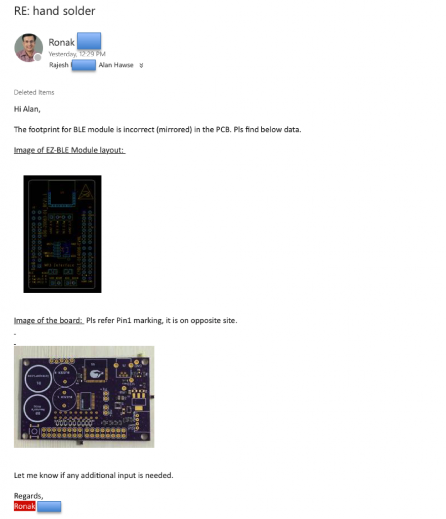
Finally I gave up and sent my board to our kit team in India.  This is not such a simple thing to do as you need to have commercial invoices for all of the stuff that I sent them… after getting it rolling and patiently waiting for three days for Fed-Ex to get it through all of the customs hoops etc. I get this email from the Kit Manager:

email

Damn damn damn… I know that I double checked the package.  That is such an amateur mistake… alway always always check your footprints.  But Ronak is right, here is a screen shot of the Eagle Layout which I clicked on Pin 2. (I rotate the image to make it line up with the data sheet)screen-shot-2016-09-24-at-8-16-22-am

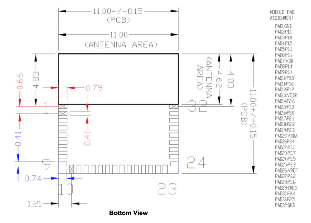
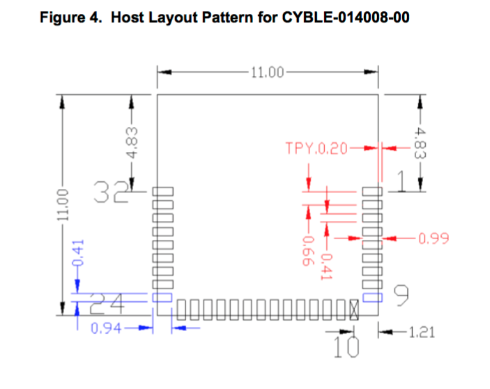
And it matches the the picture from the data sheet for the module… However… notice that it says “Bottom View” which means I flipped it.

screen-shot-2016-09-24-at-8-14-43-am

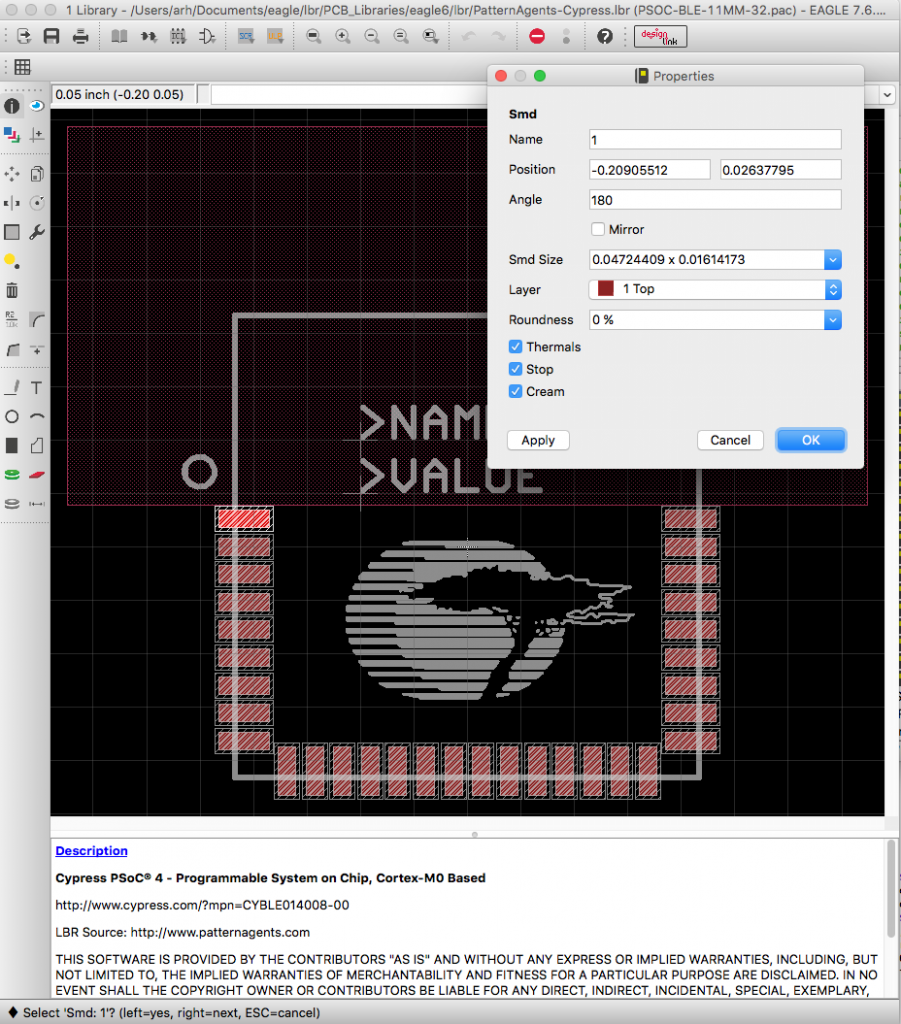
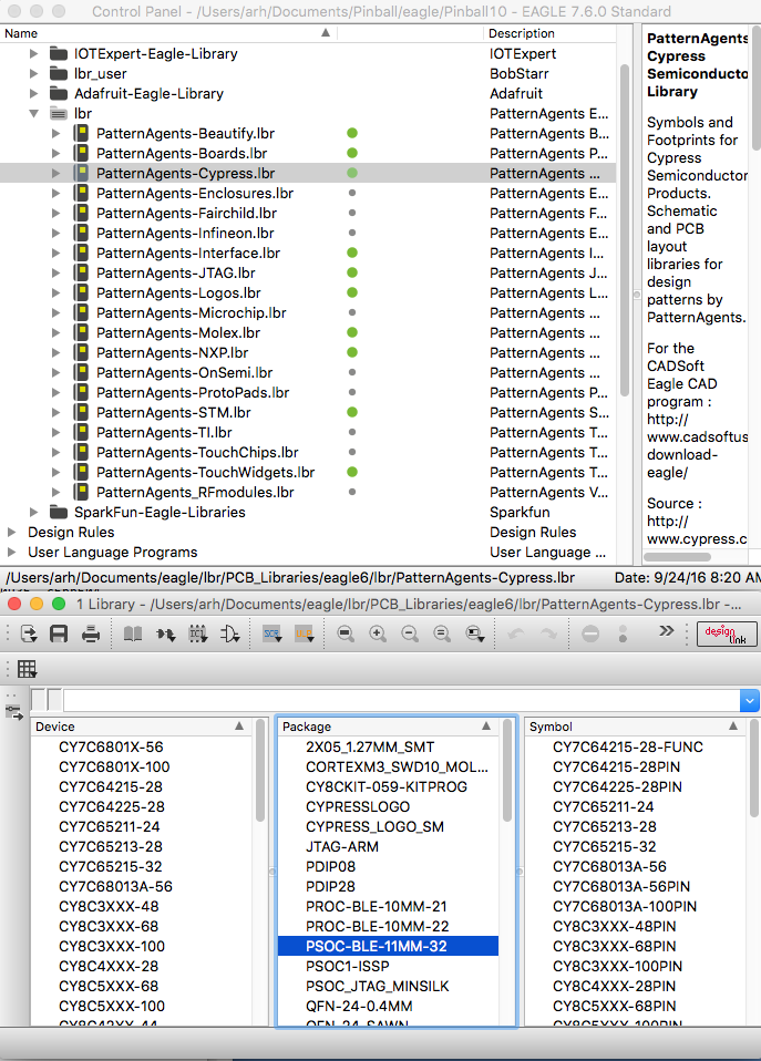
Here is a screenshot of the package in the eagle library… sure enough. It is flipped.
screen-shot-2016-09-24-at-8-24-47-am

More evidence, here is the top view:


screen-shot-2016-09-24-at-8-13-47-am

So, I need to fix the package and then re-do the layout.  I start this process by making a new branch in git.
screen-shot-2016-09-24-at-8-41-00-am

Then open the library and the package:

screen-shot-2016-09-24-at-8-40-10-am

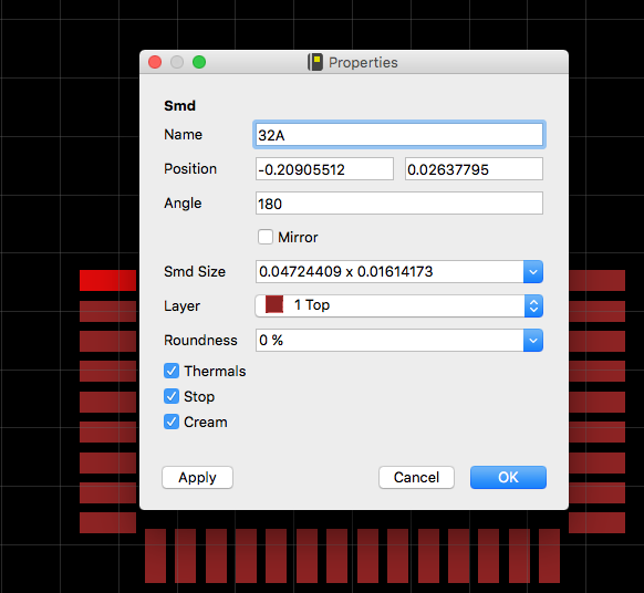
To make things easier I turn off all of the layers except for Top.  This allows me to easily click on each pad.  One thing that is a bit of a PITA is that you have to change of all of the pads to something else before you can change each one to what you want e.g. you can’t rename the pad currently named 1 to be 32 because there is already a 32.  So, what I do is rename each pad to the new name with an A on the end (see the image below).  Once that is done I go back around and remove the “A”s.

screen-shot-2016-09-24-at-8-51-18-am

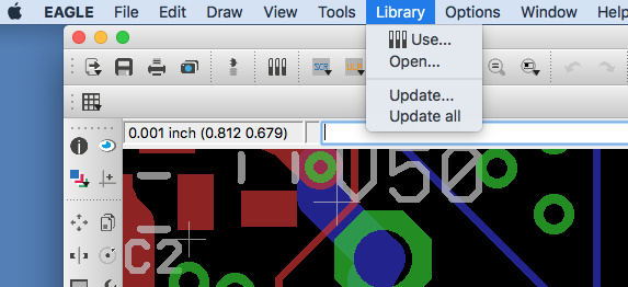
Once my package is fixed, I update the library that I am using in my layout.

screen-shot-2016-09-24-at-8-59-55-am

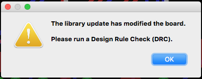
Eagle immediately tells me that I have a problem… which is true, so true.

screen-shot-2016-09-24-at-9-00-20-am

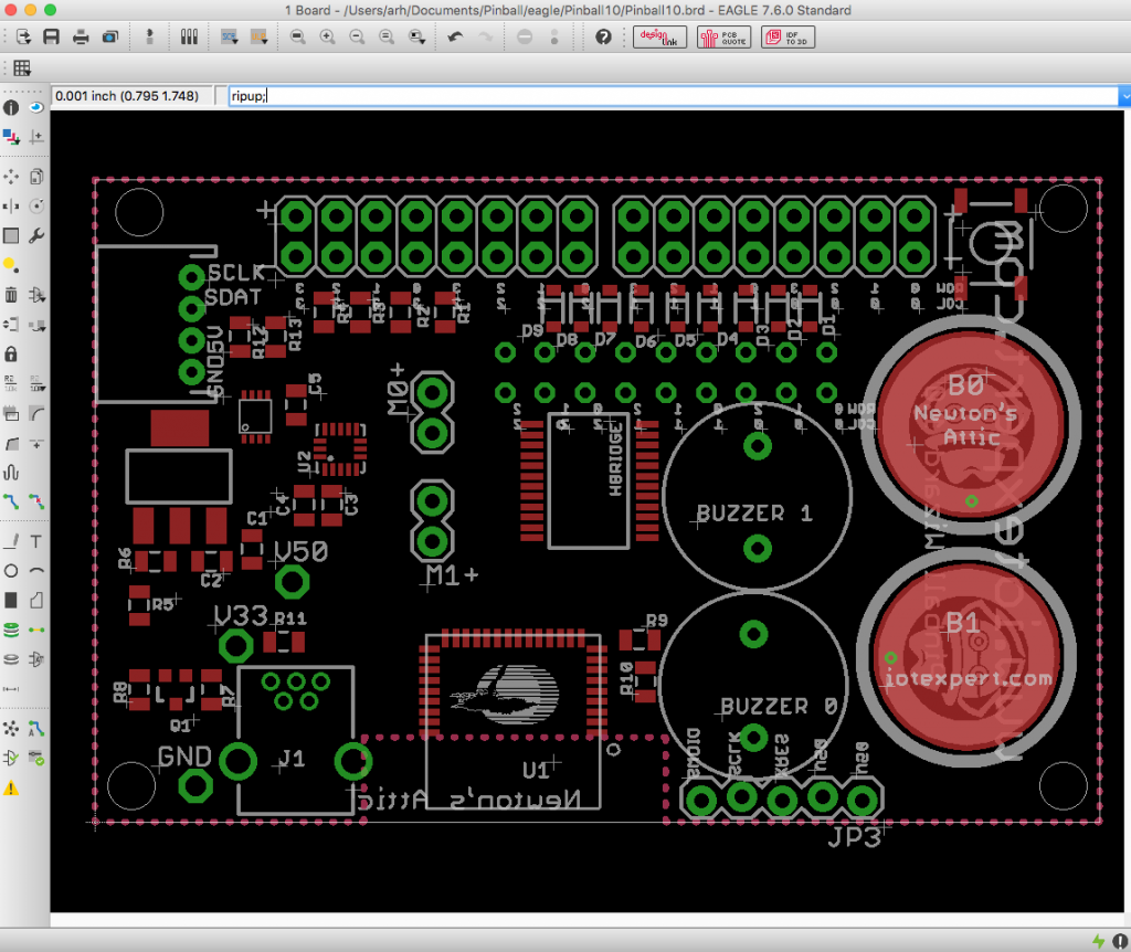
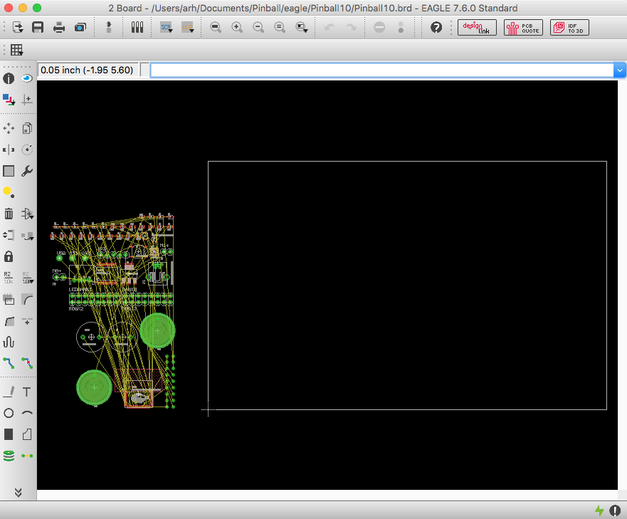
Then I ripup all of the nets, which is so sad.  The problem is that all of the things I had on the left are now on the right and visa-versa so I need to think about the whole placement.

screen-shot-2016-09-24-at-8-57-45-am

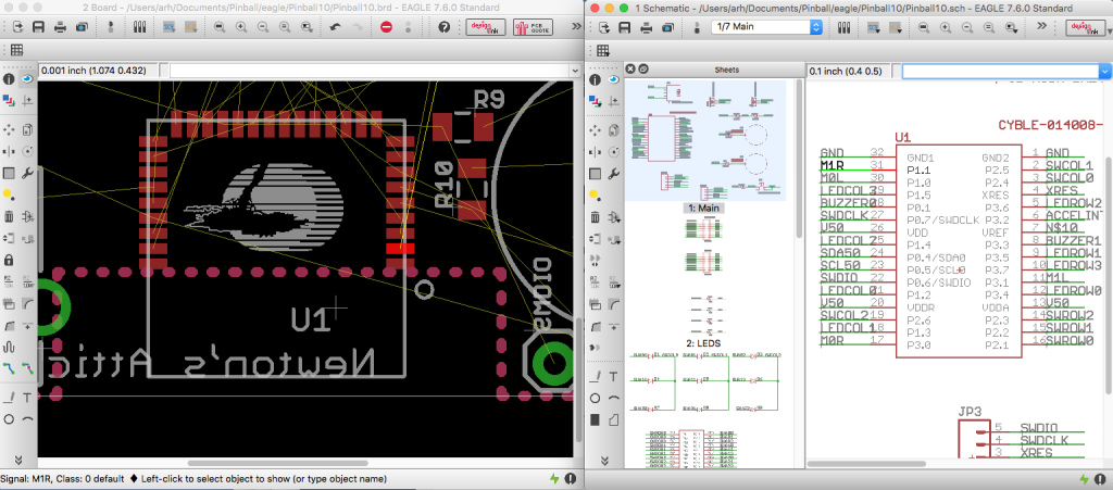
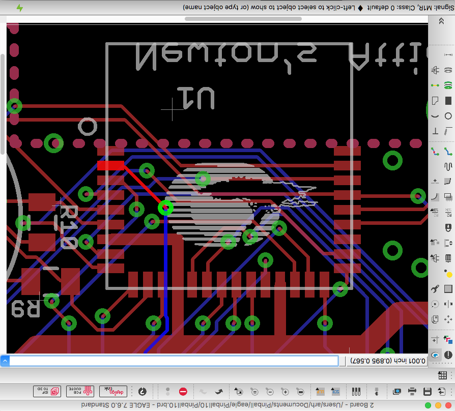
Once I have ripped up all of the nets, I then cross probe all of the nets (In this case M1R which is also pin 31) to make sure that I have the connections in the right place.

screen-shot-2016-09-24-at-9-04-12-am

OK.  Looks good.  Not commit the changes and put them back to the github with a change request.

In the next post Ill talk about the new layout.

You can find all of the source code and files at the IOTEXPERT site on github.

Index Description
Pinball: Newton's Attic Pinball An introduction to the project and the goals
Pinball: Lotsa Blinking LEDs Everyone needs a bunch of LEDs on their Pinball Machine
Pinball: Matrix LEDs (Part 1) Saving PSoC pins by using a matrix scheme
Pinball: Matrix LEDs (Part 2) Solving some problems with the matrix
Pinball: Matrix LEDs Component How to turn the Matrix LED into a component
Pinball: A Switch Matrix Implementing a bunch of switches
Pinball: Switch Matrix Component (Part 1) The switch matrix component implementation
Pinball: Switch Matrix Component (Part 2) The firmware for matrix component
Pinball: Switch Matrix Component (Part 3) Test firmware for the matrix component
Pinball: The Music Player (Part 1) The schematic and symbol for a Music Player component
Pinball: The Music Player (Part 2) The Public API for the Music Player component
Pinball: The Music Player (Part 3) The firmware to make the sweet sweet music
Pinball: The Music Player (Part 4) The test program for the music player
Pinball: The Motors + HBridge Using an Bridge to control DC Motors
Pinball: The Eagle Schematic All of the circuits into an Eagle schematic
Pinball: The Printed Circuit Board 1.0 The first Eagle PCB layout of the printed circuit board
Pinball: The PCB Version 1.0 Fail Problems with the first version of the Eagle PCB layout
Pinball: PCB Layout 1.2 Updates using Eagle Fixing the errors on the first two versions of the Eagle PCB
Pinball: Assemble and Reflow the 1.2 PCB Assembling the Eagle PCB
Pinball: Testing the Eagle PCB Firmware to test the newly built Pinball printed circuit board
Pinball: Debugging the Motor Driver Fixing the motor driver PSoC project
Pinball: Hot-Air Reworking the Accelerometer Solder Using a Hot-Air Rework tool to reflow a QFN
Pinball: Debugging the LM317 Power Supply- A Tale of Getting Lucky Debugging the LM317/LM117 power supply

Pinball: The Printed Circuit Board Version 1.0

I am supposed to be good at this stuff.  What is this stuff?  Simple, everything engineering.  Unfortunately, I suck at PCB layout.  This is something that I am loath to admit because it is so frustrating. There it is.  But I need a PCB to make this work, so here we go again.  What also sucks is that I entitled this post “Pinball: The Printed Circuit Board Version 1.0” because I know that it is going to take multiple versions.  I don’t know what the exact cause is going to be this time.  But it will be something.  Enough whining.  Onto the task at hand.

When you start from an empty board Eagle gives you the tantalizing picture of a blank board with the components you need laid out neatly.  All you need to do is move them onto the tabla rosa.

Screen Shot 2016-08-29 at 5.21.40 AM

Initially there are several constraints that I am trying to satisfy.

  1. I want the board to cost <$5 so it needs to be <5 Sq. Inches
  2. The Pinball machine has space on the front for something roughly the shape of a deck of cards (2.5″ x 3.5″)
  3. The power connector needs to be at the bottom
  4. The user interface needs to be at the right (buzzers, capsense buttons) because Billy is going to cover the left side with some acrylic.

We had originally thought about making a 3-D printed box for the design, but decided that it would be cool to be able to see the board.  It also saves several dollars in cost to get rid of the box.

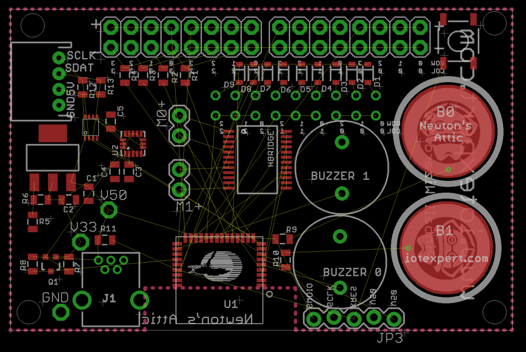
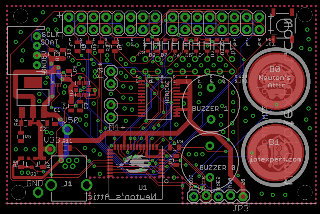
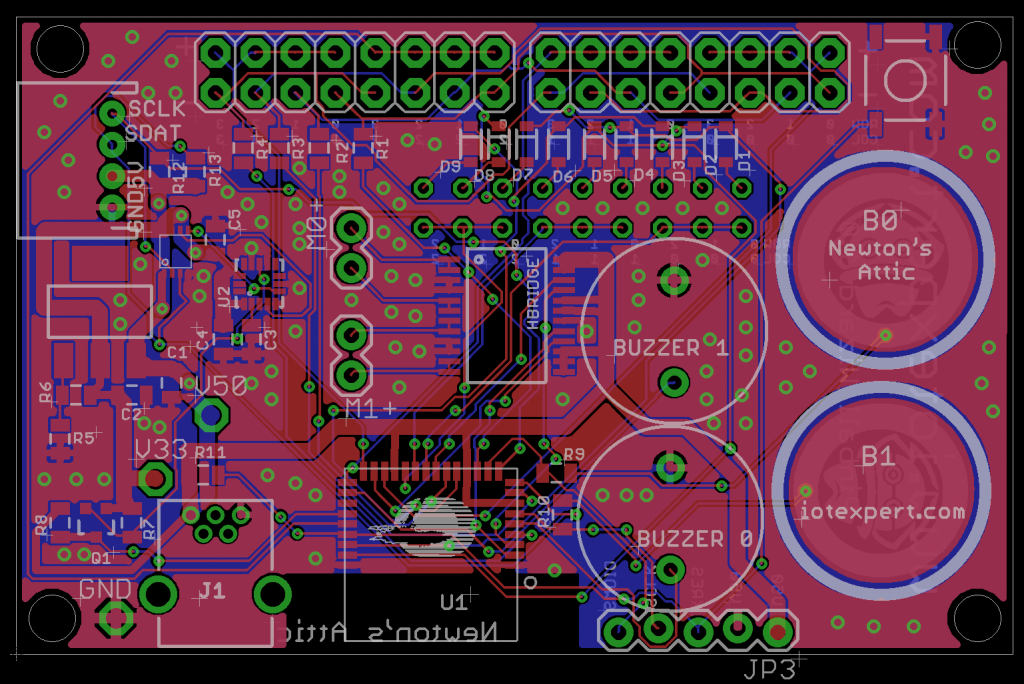
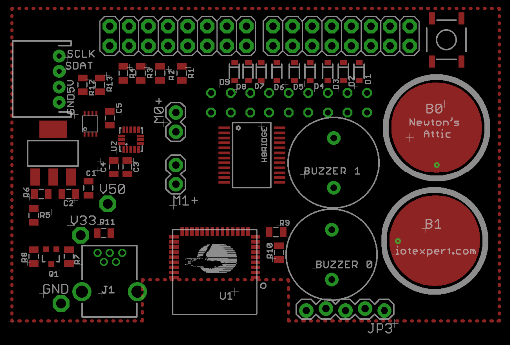
All right, I suppose that it is time to get to it.  First I move all of the component from “off the board” onto the board.  They all need to appear inside of the dimension layer.  If you look at the pinball machine I want all of the wire to come from the top and then go down into the machine.  So I place the holes for the LEDs and the Switches at the top of the board.  I want the user interface to be on the right side of the board (since most of the world is right handed… sorry about the left handed people).  So, I place the capsense buttons and the reset button on the right side of the board.  The BLE Module needs to have the space under the antenna without a ground plane and without signals, so I decide to put it at the bottom of the board.  I decide that the I2C port for the LCD will go on the left side of the board as that will make the connection to the LCD on the left side of the pinball machine easier.  Finally I put the accelerometer and all of the stuff that it takes to run it on left left side as well.

screen-shot-2016-09-25-at-10-07-51-am

Once the placement is all done, it is time to route the signals.  I do this through a combination of the autorouter and manual routes.  After I get all of the routes done, I place GND via(s) all over the board to connect the top and bottom ground pours.

screen-shot-2016-09-25-at-10-06-25-am

When I click the rats nest button the pours happen and I can see that there are no unrouted nets.

screen-shot-2016-09-25-at-10-05-40-am

Next I  do the top silkscreen

screen-shot-2016-09-25-at-10-10-09-am

Finally the bottom silkscreen

screen-shot-2016-09-25-at-10-11-31-am

The last step is to re-check all of my printed circuit board rules (the subject of the next post).  Now that I have a printed circuit board I can send to OSHPark to be made.

You can find all of the source code and files at the IOTEXPERT site on github.

Index Description
Pinball: Newton's Attic Pinball An introduction to the project and the goals
Pinball: Lotsa Blinking LEDs Everyone needs a bunch of LEDs on their Pinball Machine
Pinball: Matrix LEDs (Part 1) Saving PSoC pins by using a matrix scheme
Pinball: Matrix LEDs (Part 2) Solving some problems with the matrix
Pinball: Matrix LEDs Component How to turn the Matrix LED into a component
Pinball: A Switch Matrix Implementing a bunch of switches
Pinball: Switch Matrix Component (Part 1) The switch matrix component implementation
Pinball: Switch Matrix Component (Part 2) The firmware for matrix component
Pinball: Switch Matrix Component (Part 3) Test firmware for the matrix component
Pinball: The Music Player (Part 1) The schematic and symbol for a Music Player component
Pinball: The Music Player (Part 2) The Public API for the Music Player component
Pinball: The Music Player (Part 3) The firmware to make the sweet sweet music
Pinball: The Music Player (Part 4) The test program for the music player
Pinball: The Motors + HBridge Using an Bridge to control DC Motors
Pinball: The Eagle Schematic All of the circuits into an Eagle schematic
Pinball: The Printed Circuit Board 1.0 The first Eagle PCB layout of the printed circuit board
Pinball: The PCB Version 1.0 Fail Problems with the first version of the Eagle PCB layout
Pinball: PCB Layout 1.2 Updates using Eagle Fixing the errors on the first two versions of the Eagle PCB
Pinball: Assemble and Reflow the 1.2 PCB Assembling the Eagle PCB
Pinball: Testing the Eagle PCB Firmware to test the newly built Pinball printed circuit board
Pinball: Debugging the Motor Driver Fixing the motor driver PSoC project
Pinball: Hot-Air Reworking the Accelerometer Solder Using a Hot-Air Rework tool to reflow a QFN
Pinball: Debugging the LM317 Power Supply- A Tale of Getting Lucky Debugging the LM317/LM117 power supply

Pinball: The Eagle Schematic

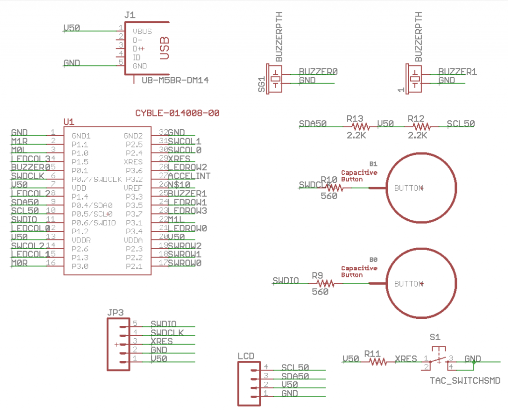
In the last bunch of posts I have talked about the main systems of the pinball machine electronics package.  Now it is time to assemble all of those pieces into a complete system on an Eagle schematic which you can find in the “eagle” directory on the github site.

I use the multipage capability of Eagle to partition the schematic into 7 pages.

  1. Main Page
  2. LEDs
  3. Switches
  4. Accelerometer
  5. Power
  6. Motors
  7. Test Points

The main page contains the

  1. PSoCBLE module:  Notice that I used every single pin except for VRef.  Also notice that I overloaded SWD-Clock and SWD-IO pins by attaching capsense buttons to those pins.  This means that I will never be able to debug and use Capsense at the same time.
  2. USB Connector:  When I was trying to figure out how to make the board less expensive my son suggested that everybody has a USB charger, so why don’t you just power the pinball machine with that?  I thought that this was a great idea as it eliminates a $5+ wall wart.
  3. Two buzzers.  These are super simple low cost 12mm through hole buzzers which are used by the MusicPlayer component.
  4. Two capsense buttons multiplexed to the SWDCLK and SWDIO pins of the chip.  Notice that they have a 560Ohm series resistor
  5. The reset button for the system which just pulls down the XRES when you press the button.  It also has the 10K pullup resistor which pulls up XRES when the button is not being pressed
  6. Pull-up resistors for the 5V I2C bus.
  7. A 5-Pin programming plug for the MiniProg-3 connected to SWDIO and SWDCLK and the Power/Ground
  8. A plug for the I2C LCD to connect to the I2C Bus

screen-shot-2016-09-25-at-6-44-48-am

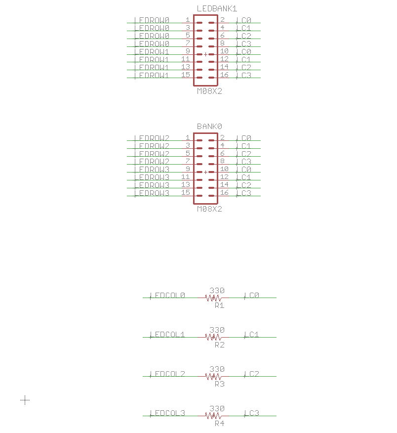
Page two of the schematic contains two connectors for the LEDs which I talked about in detail in the Matrix LED Posts .  It also contains the current limiting resistors.  In order to save money in the BOM I am not going to actually put connectors into the 100mil center holes, but will let the kids learn to solder by attaching the wires directly into the holes with solder.

screen-shot-2016-09-25-at-6-45-06-am

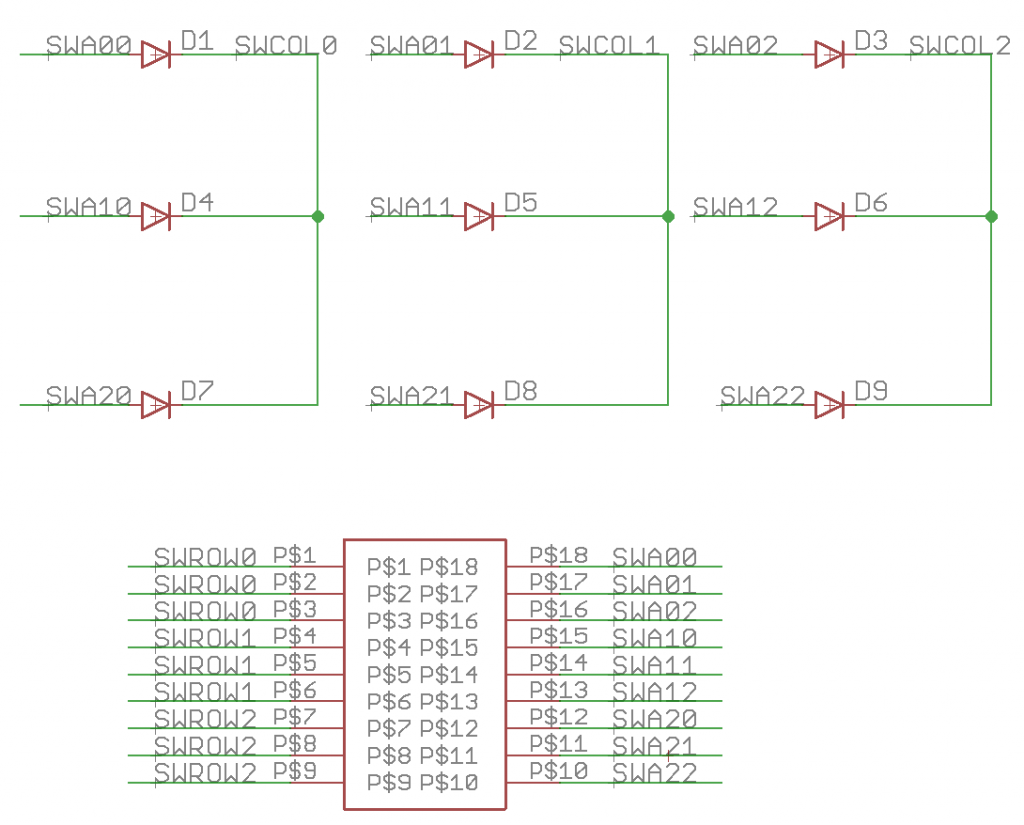
Page three of the schematic contains the switch matrix connectors and diodes.

screen-shot-2016-09-25-at-6-45-20-am

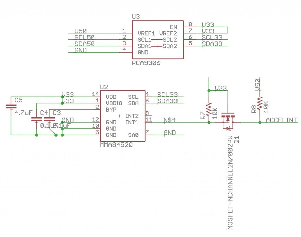
I thought that it would be a really cool idea to have an accelerometer on the board to provide a tilt functionality.  This actually turned out to be a serious PITA because I couldn’t find a cheap accelerometer that was 5v.  So, in addition to the accelerometer I have to provide a level translator for the I2C bus (PCA9306) and a level translator for the Accelerometer interrupt line (the mostfet and pull-up resistors).  I also have to provide a 3.3v power supply (next page of the schematic)

screen-shot-2016-09-25-at-6-45-36-am

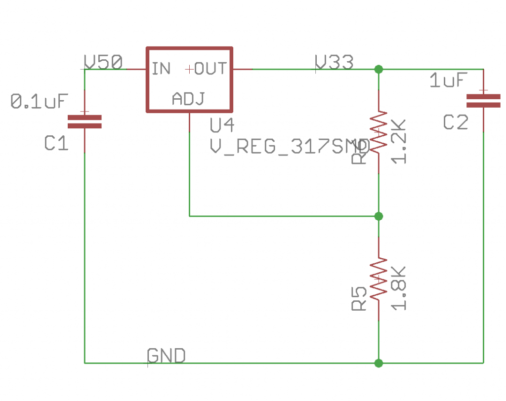
The 3.3v accelerometer requires a 3.3v power supply, so on this page I use an REG317 to create 3.3v from the VBUS power supply.

screen-shot-2016-09-25-at-6-45-54-am

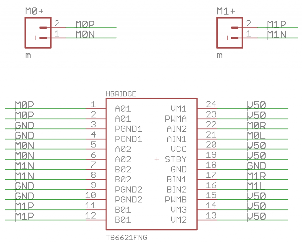
In order to drive the two brushed DC motors I use a TB6621 motor driver chip that contains two H-Bridges.

screen-shot-2016-09-25-at-6-46-04-am

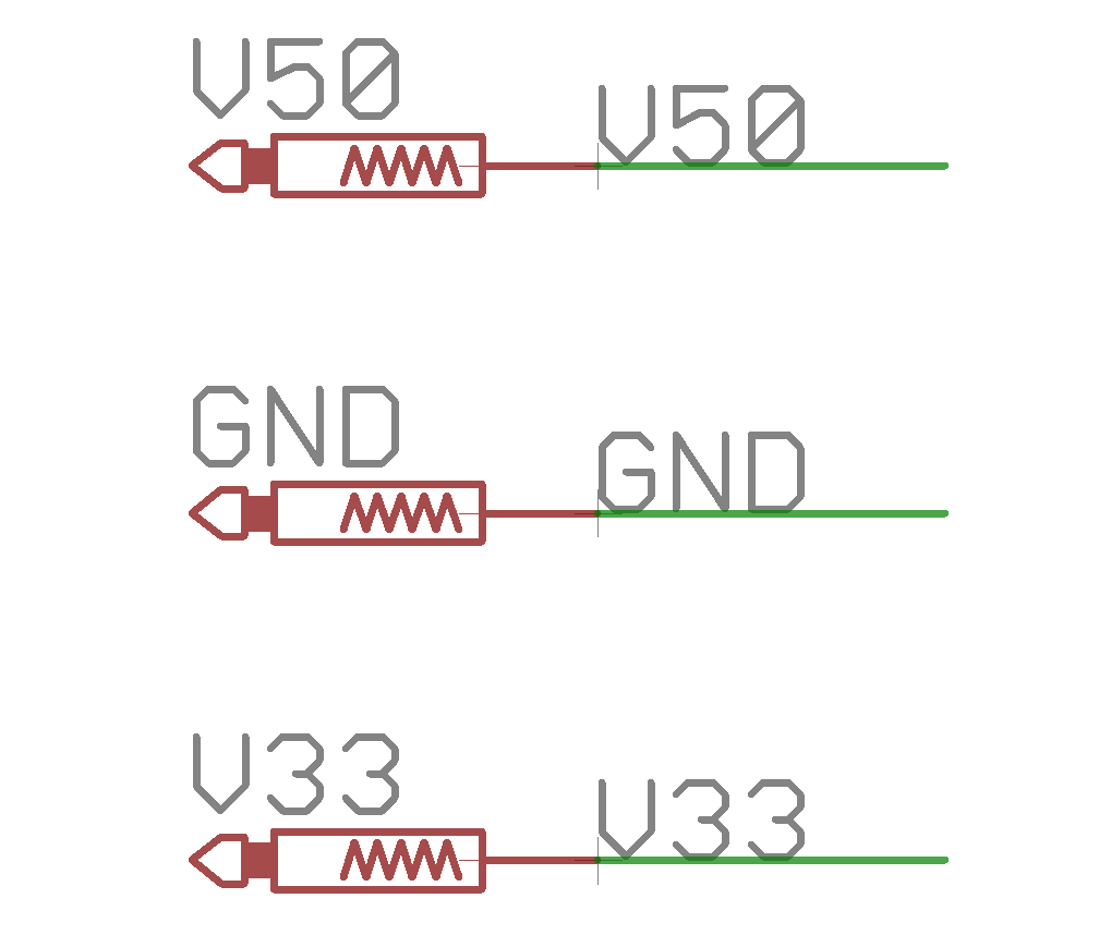
Finally I like to have test points on the board to measure stuff while I am assembling the board.

screen-shot-2016-09-25-at-6-46-15-am

In the next post Ill talk about the creation of the layout for the printed circuit board.

You can find all of the source code and files at the IOTEXPERT site on github.

Index Description
Pinball: Newton's Attic Pinball An introduction to the project and the goals
Pinball: Lotsa Blinking LEDs Everyone needs a bunch of LEDs on their Pinball Machine
Pinball: Matrix LEDs (Part 1) Saving PSoC pins by using a matrix scheme
Pinball: Matrix LEDs (Part 2) Solving some problems with the matrix
Pinball: Matrix LEDs Component How to turn the Matrix LED into a component
Pinball: A Switch Matrix Implementing a bunch of switches
Pinball: Switch Matrix Component (Part 1) The switch matrix component implementation
Pinball: Switch Matrix Component (Part 2) The firmware for matrix component
Pinball: Switch Matrix Component (Part 3) Test firmware for the matrix component
Pinball: The Music Player (Part 1) The schematic and symbol for a Music Player component
Pinball: The Music Player (Part 2) The Public API for the Music Player component
Pinball: The Music Player (Part 3) The firmware to make the sweet sweet music
Pinball: The Music Player (Part 4) The test program for the music player
Pinball: The Motors + HBridge Using an Bridge to control DC Motors
Pinball: The Eagle Schematic All of the circuits into an Eagle schematic
Pinball: The Printed Circuit Board 1.0 The first Eagle PCB layout of the printed circuit board
Pinball: The PCB Version 1.0 Fail Problems with the first version of the Eagle PCB layout
Pinball: PCB Layout 1.2 Updates using Eagle Fixing the errors on the first two versions of the Eagle PCB
Pinball: Assemble and Reflow the 1.2 PCB Assembling the Eagle PCB
Pinball: Testing the Eagle PCB Firmware to test the newly built Pinball printed circuit board
Pinball: Debugging the Motor Driver Fixing the motor driver PSoC project
Pinball: Hot-Air Reworking the Accelerometer Solder Using a Hot-Air Rework tool to reflow a QFN
Pinball: Debugging the LM317 Power Supply- A Tale of Getting Lucky Debugging the LM317/LM117 power supply

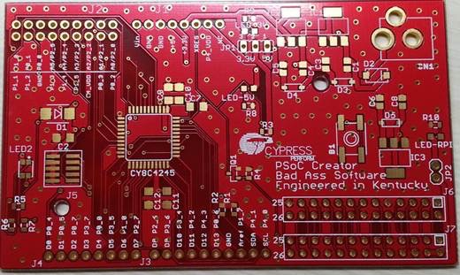
The Creek: CYPI, a Raspberry Pi to Arduino Bridge

In the summer of 2013, I decided that I needed to design a printed circuit board.  I had worked on sections of chips but no PCBs.  I didnt really know which tool to use, but after looking around a bit it seemed like Eagle was a good simple choice as it had wide adoption in the Maker community.  At that point in time the Elkhorn Creek Measuring System was being run off a Raspberry PI and a PSoC5LP but Cypress had just released a new family of chips called the PSoC4200.  I thought that it would be a cool idea to have a PSoC to Raspberry PI bridge board.  So this is what I did.

On the bottom of the board I wanted female pins that matched the Raspberry PI, and on the top I wanted an Arduino pins.  Bottom line, I decided to build a board that was very similar to the CY8CKIT-042 except for having Raspberry PI GPIOs on the bottom of the board.

My board has:

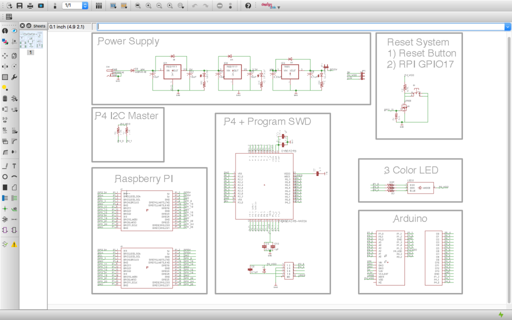
  • Power System: Both 3.3v and 5.0v for the PSoC as well as 5.0v@1.0A for the Raspberry PI.
  • Reset System: A RPi connection to the PSoC and Arduino XRES.
  • An I2C connection between the RPi and the PSoC including the pullup resistors
  • A 3-Color LED
  • Arduino pins that match the pinout of the CY8CKIT-042

The overall schematic

Overall CYPI Schematic

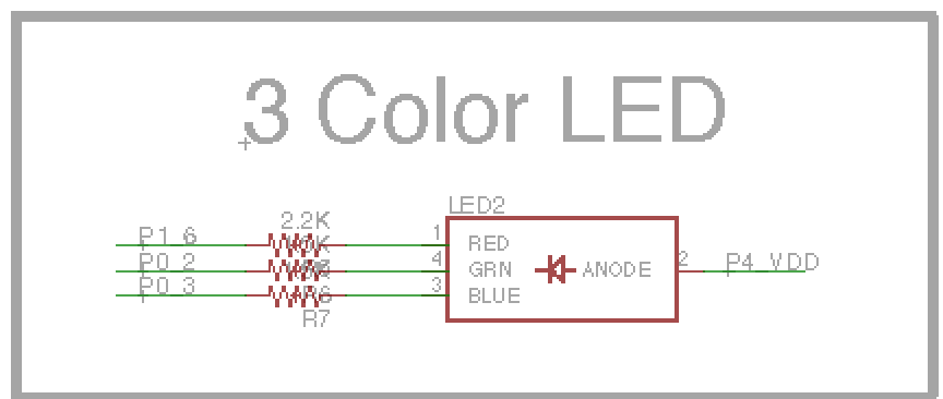
I used the same RGB 3 Color LED (CLV1A-FKB- CJ1M1F1BB7R4S3) as exists on the CY8CKIT-042.

Screen Shot 2016-01-30 at 8.29.32 PM

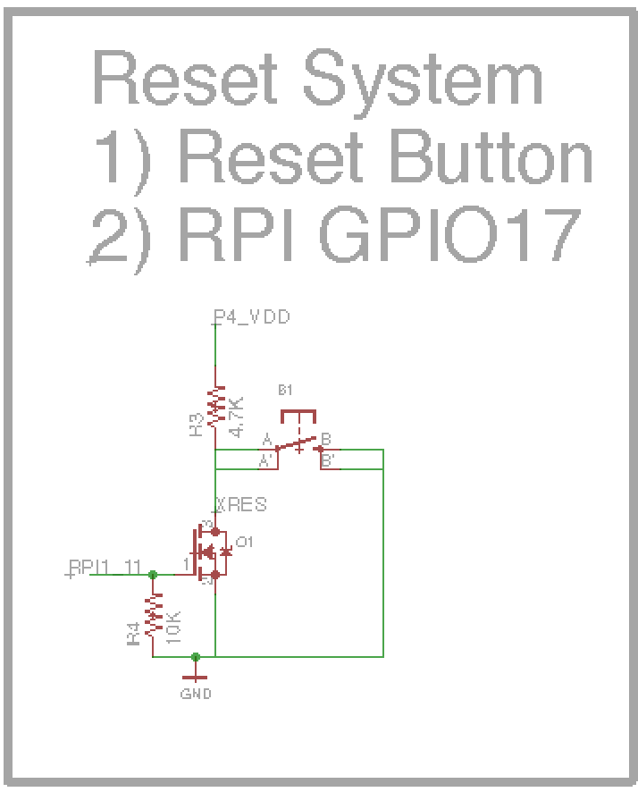
I wanted to be able to reset PSoC and Arduino from the Raspberry Pi so I attached the RPi GPIO 1_11 to a pulldown transistor that is connected to the XRES of the Arduino and PSoC.  I also attached a small pushbutton to enable a user reset.

Screen Shot 2016-01-30 at 8.29.19 PM

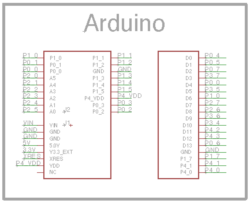
I copied the Arduino pin out of the CY8CKIT-042.  This would allow me to easily use all of the projects that I had already developed that that development kit.

Screen Shot 2016-01-30 at 8.29.03 PM

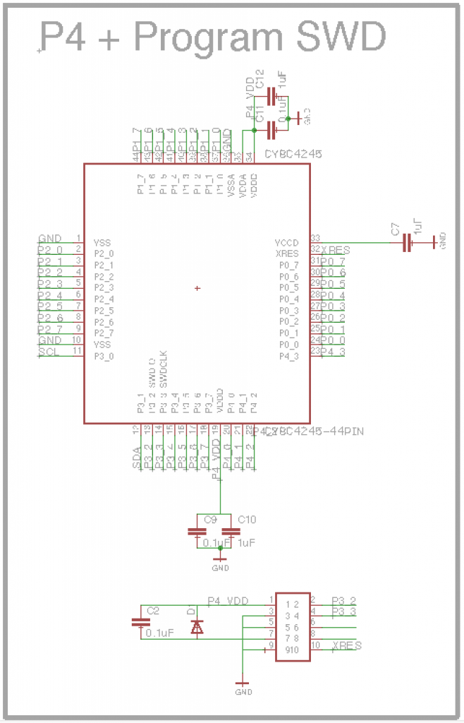
This section of the schematic has the required power supply decoupling capacitors.  It also has the ARM standard 10 Pin programming header which allows me to program the PSoC using a MiniProg-3.

Screen Shot 2016-01-30 at 8.28.46 PM

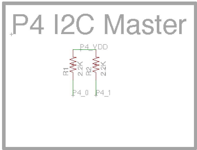
I provided pull up resistors on the PSoC P4[0] and P4[1] to easily enable the PSoC to serve as an I2C Master for the Arduino shield.

Screen Shot 2016-01-30 at 8.28.18 PM

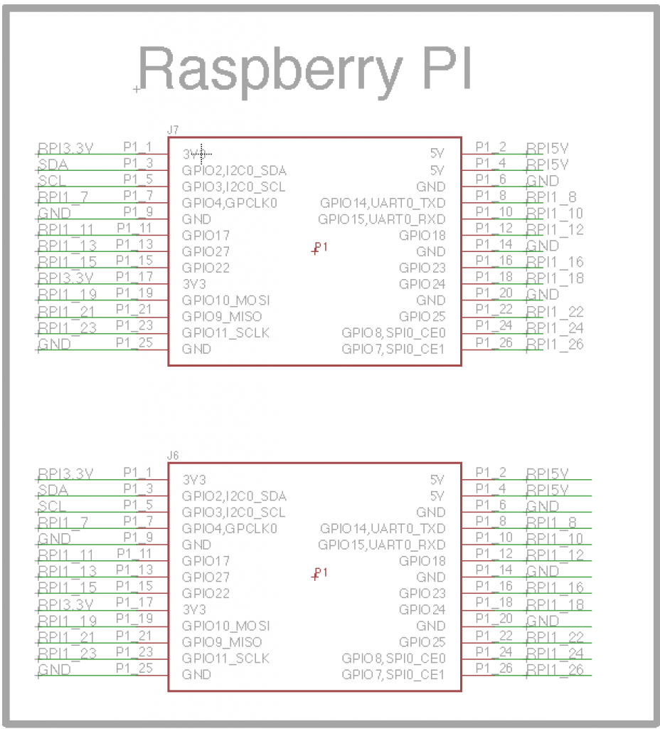
The connection to get data between the RPi and the PSoC is I2C.  The PSoC is setup as an I2C slave and the RPi is the master.  The connection on the RPi uses the RPI1_3 and RPI1_4 GPIOs.  On the PSoC it is connected to P3[0] and P3[1].

Screen Shot 2016-01-30 at 8.28.01 PM

The power supply turned out to be by far the most difficult part of the project.  In the first version of the board I chose a regulator that was to small to supply the Raspberry PI.  When the RPi was plugged in, the regulator immediately went into thermal shutdown.  In general this sucked as the PSoC Applications Manager warned me to pick a big enough regulator.  Oh well.  In the final version of the board I used a 7805 to supply the RPi, this regulator has a giant tab which allows you to sink heat into the ground plane of the board.  On the board I also provide a 5.0V supply and a 3.3V supply for the PSoC using a 1117 regulator.

Screen Shot 2016-01-30 at 8.27.34 PM

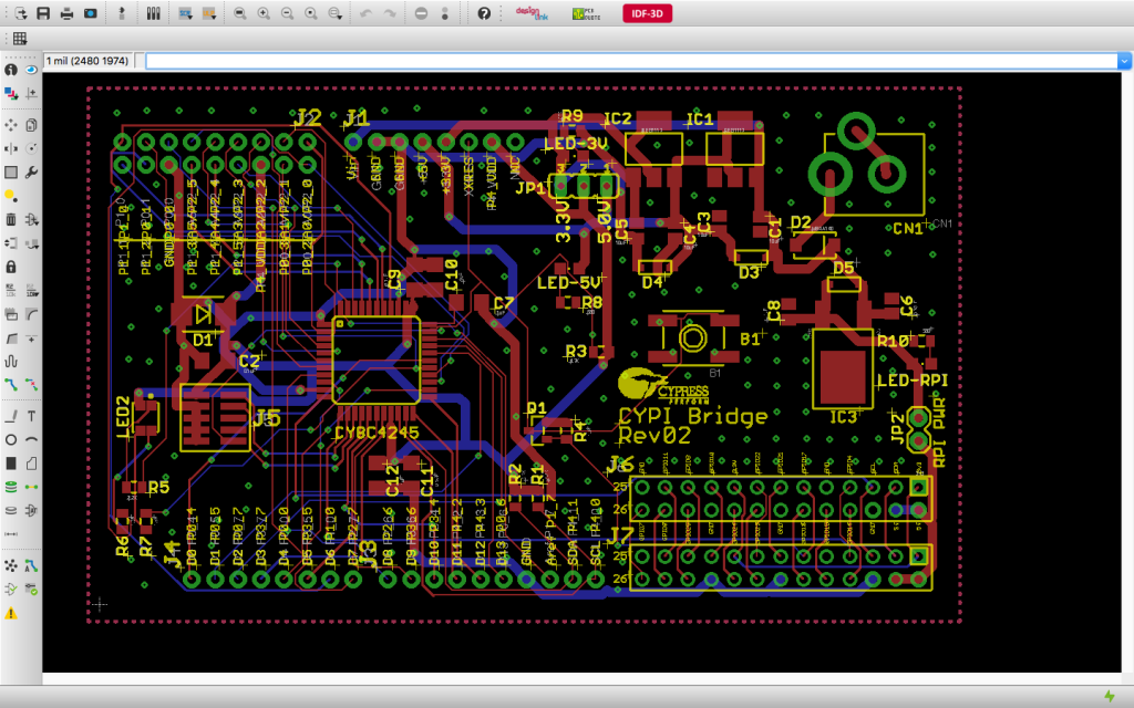
Here is a picture of the final layout

Overall Layout

And here is a picture of the first version of the board.

IMG_1176 (1)

On thing that you might notice on this board is that the vias are exposed.  What I didnt know is that you need to tell Eagle to “tent” the vias so that they are covered with solder mask.

There is a lot going on in the layout and it is probably easiest to review the layout using eagle.  You can get the design from github at https://github.com/iotexpert/cypi

Index Description
The Creek: IOT for the Elkhorn Creek Introduction
The Creek: Solution Architecture 1.0 Overall architecture
The Creek: Creek Board 1.1 Eagle layout of the board
The Creek: Creek Board 1.0 – RCCA A discussion of the errors in the 1.0 board
The Creek: CYPI, a Raspberry Pi to Arduino Bridge PSoC4 <--> Raspberry Pi Bridge Board
The Creek: PSoC4 Creator Schematic and Firmware Firmware to interface with the temperature and pressure sensors
The Creek: Testing the Firmware Using tools to verify that the PSoC 4 Firmware is working correctly
The Creek: Testing the Bootloader Make sure that you can load new firmware into the PSoC
The Creek: Software Architecture All of the Raspberry Pi software connections
The Creek: Install MySql Instruction to configure MySql
The Creek: Install Tomcat Instruction to configure Tomcat JSP Server
The Creek: Data Collection Java (Part 1) The Java program that reads the I2C and saves it in the database
The Creek: Data Collection Java (Part 2) The Java program that reads the I2C and saves it in the database
The Creek: Create the Chart with JFreeChart Using open source Java charting software to create plots of the Creek Depth
The Creek: Flood Event Data Processor A batch program to create analyze the database and create a table of flood events
The Creek: Flood Event Web Page A batch program to create the flood event web page
The Creek: Creek Server 1.1 Updates to all of the back off server programs to integrate charts
The Creek: JSP Web Page for www.elkhorn-creek.org The JSP program to make the table and display the website
The Creek: Raspberry Pi Clock Stretching Sorting out a bug in the system having to do with the Broadcomm Raspberry Pi Master not functioning well with clock stretching
The Creek: Creek Server 1.2 Caching the web pages to make them faster

The Creek: Creek Board 1.0 – RCCA

At my company Cypress, “RCCA” is an abbreviation for “Root Cause Corrective Action”.  It is a formal process for changing the way that you work to prevent an error from happening again.

Unfortunately the title of this post is “Creek Board 1.0 – RCCA”.  What that means is that the first time I sent the Creek Board to be manufactured I made an error, in fact a really stupid error.  Specifically,  the error that I made was a fundamental failure of not having an LVS (Layout versus Schematic) clean design.  If you google “blue wire pcb” the first search result you will find is “Printed Circuit Board Repair and Rework Guides”,  I had no idea why blue wires were used to fix printed circuit boards so I called my friend Dave Van Ness.  He is an old grey beard type of guy.  He told me that the blue wire was traditionally an “official fix” to a circuit board.  It was used because other colors were already assigned (Red to power, Black to ground) etc.  I guess that I thumbed my nose at tradition by fixing my PCB with a red wire.

IMG_2024

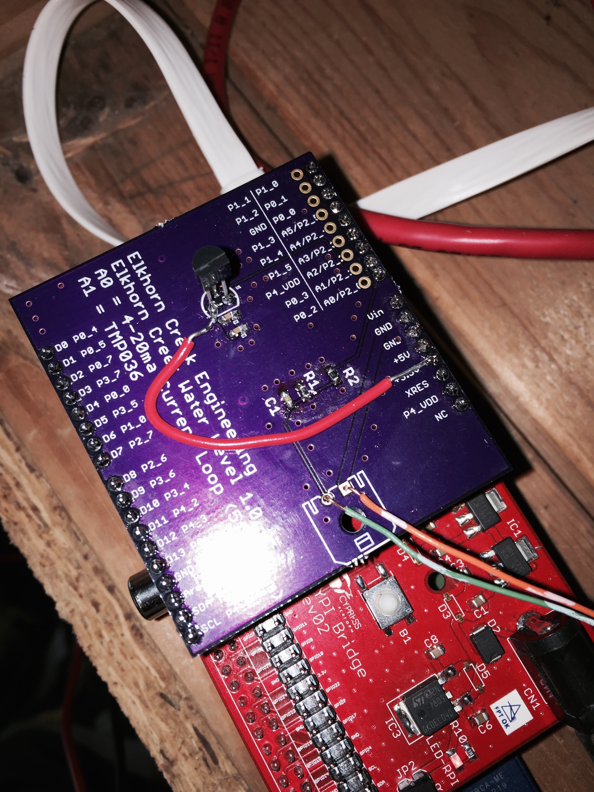
After laying out a printed circuit board, the last step is to surround the board with a ground plane on the top and bottom of the board.  Then you press the “ratsnest” button on Eagle.  Then Eagle does a “pour” which fills in the empty space of the board with a ground plane.  It then will update the bottom of the screen with the message “Ratsnet: Nothing to do!” which means all of the schematic and layout connections are complete.  Or, if there are connections that still need to be made, it will update the layout with yellow “air wires” and it will give you a message like “Ratsnest: 1 airwires.”  If you send the board to be made with an airwire, that is exactly what you will get.  I will tell you that air doesn’t conduct electricity very well and you will end up needing your soldering iron.

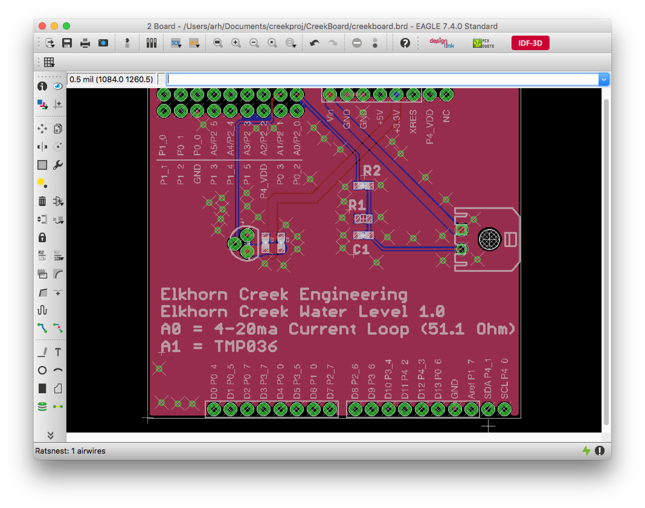
In this case I missed seeing the tiny little airwire.  See if you can see it:creek1.0board

It is hard to see, eh?  In the next picture I turned off the ground layer and zoomed in so you can see that I am missing a power connection between the top and the bottom of the board.  I highlighted this issue by clicking on the “Show Objects” at the top of the toolbar, then clicking on yellow wire.  When I do that, Eagle tells me what the net is that is unconnected and it highlights every object that is attached to that net.

zoom-of-error

So now what?

What I ended up doing is the normal Cypress thing.  I created a “tapeout checklist”.  The checklist contains a list of all of the things that I double check before I send a PCB to be manufactured.  Here is my current (and short) checklist:

  • No remaining airwires
  • Vias tented (or not)
  • Silkscreen on all connections
  • Test points on key nets
  • No DRC errors

Index Description
The Creek: IOT for the Elkhorn Creek Introduction
The Creek: Solution Architecture 1.0 Overall architecture
The Creek: Creek Board 1.1 Eagle layout of the board
The Creek: Creek Board 1.0 – RCCA A discussion of the errors in the 1.0 board
The Creek: CYPI, a Raspberry Pi to Arduino Bridge PSoC4 <--> Raspberry Pi Bridge Board
The Creek: PSoC4 Creator Schematic and Firmware Firmware to interface with the temperature and pressure sensors
The Creek: Testing the Firmware Using tools to verify that the PSoC 4 Firmware is working correctly
The Creek: Testing the Bootloader Make sure that you can load new firmware into the PSoC
The Creek: Software Architecture All of the Raspberry Pi software connections
The Creek: Install MySql Instruction to configure MySql
The Creek: Install Tomcat Instruction to configure Tomcat JSP Server
The Creek: Data Collection Java (Part 1) The Java program that reads the I2C and saves it in the database
The Creek: Data Collection Java (Part 2) The Java program that reads the I2C and saves it in the database
The Creek: Create the Chart with JFreeChart Using open source Java charting software to create plots of the Creek Depth
The Creek: Flood Event Data Processor A batch program to create analyze the database and create a table of flood events
The Creek: Flood Event Web Page A batch program to create the flood event web page
The Creek: Creek Server 1.1 Updates to all of the back off server programs to integrate charts
The Creek: JSP Web Page for www.elkhorn-creek.org The JSP program to make the table and display the website
The Creek: Raspberry Pi Clock Stretching Sorting out a bug in the system having to do with the Broadcomm Raspberry Pi Master not functioning well with clock stretching
The Creek: Creek Server 1.2 Caching the web pages to make them faster

The Creek: Creek Board 1.1

In the previous post I described the entire system architecture.  In this post, I am going to describe the Arduino shield that I unfortunately call “Elkhorn Creek Water Level 1.1”.  It is unfortunate because in version 1.0 I made a really stupid error which ruined the first run of printed circuit boards.  You can read more about how I made the error and what I am doing in the future in the post Creek Board 1.0 RCCA.

To make this system work I need to be able to interface the PSoC4200 with two sensors:

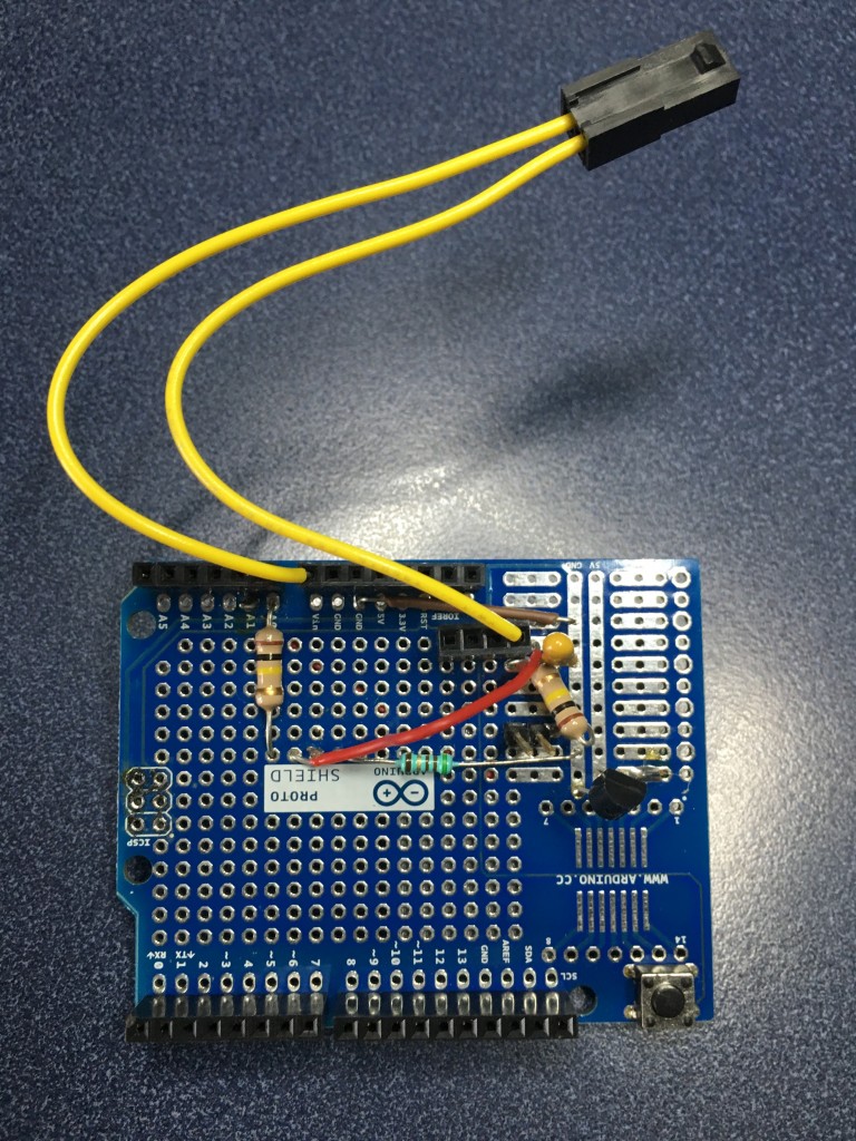
Both of these sensors are subject to environmental noise so they both have capacitive or RC filters connected to them.  I originally built a prototype of this board using a proto board.  However, it was a PITA because the wires would come loose and the system would stop working.

IMG_2655

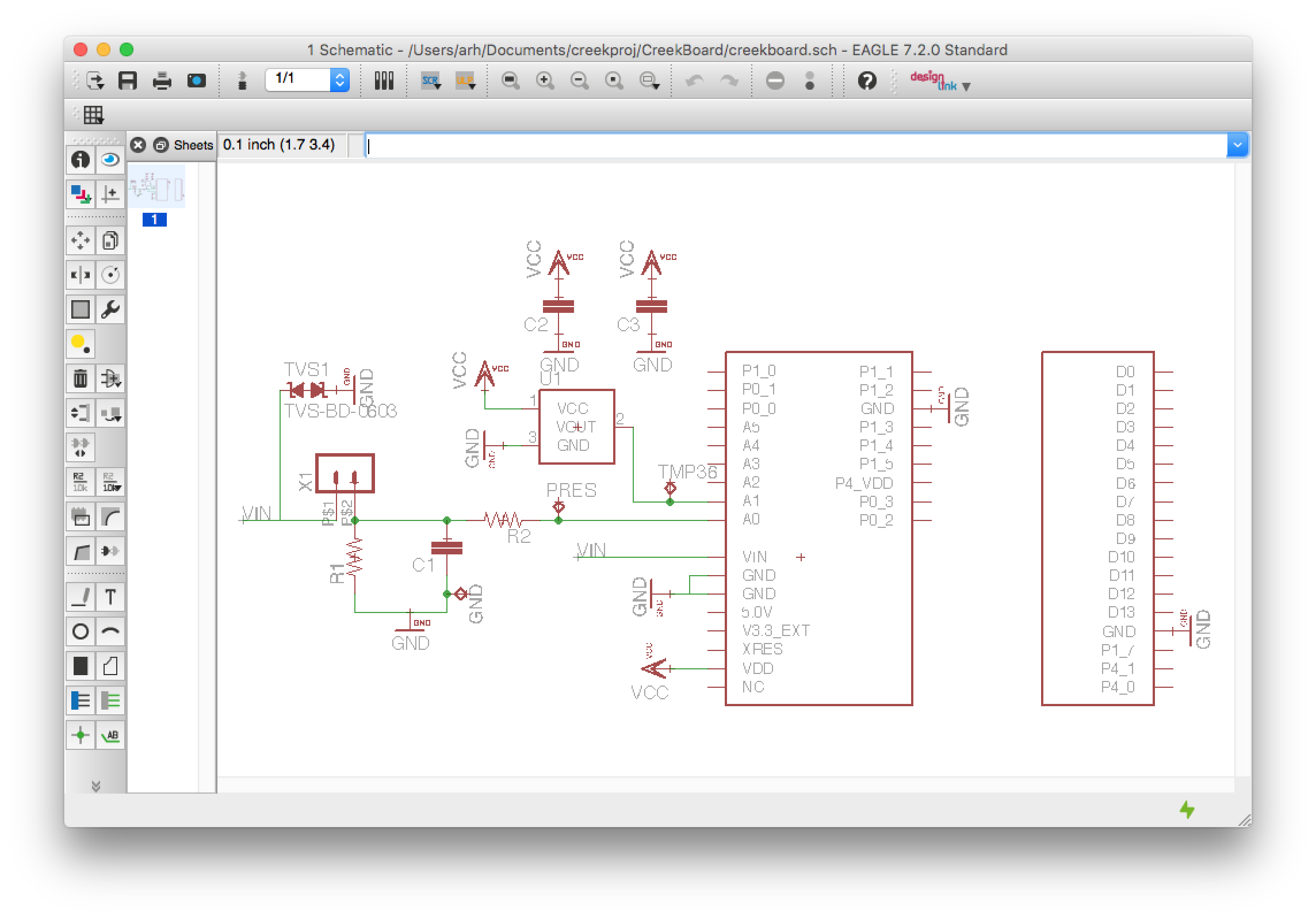
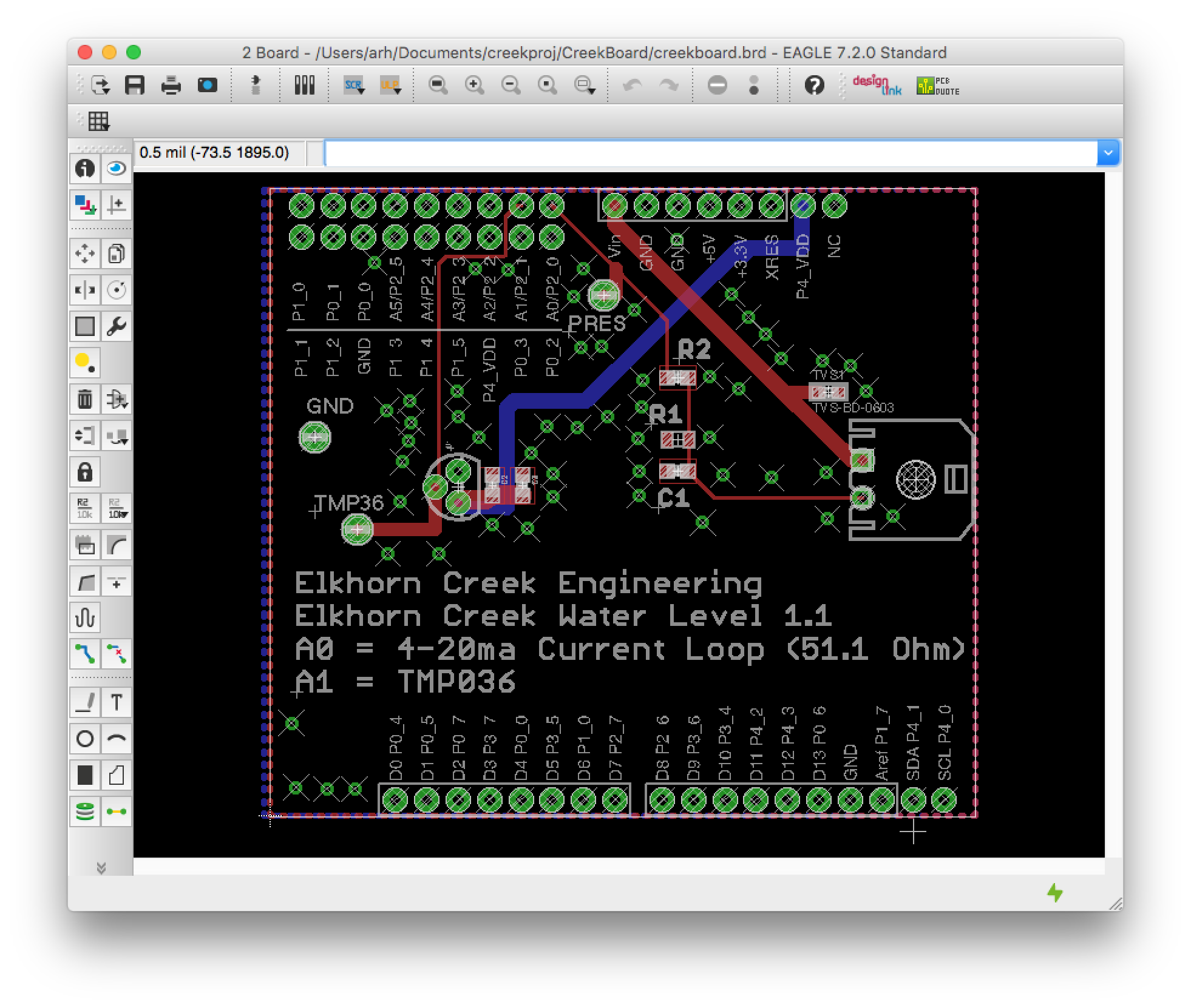
So I decided to make a real PCB.  To do the design, I used the Eagle 7.2 PCB editor as it seemed like it had the most support from the maker community.  The schematic for the system is fairly simple.  It has

  • Pressure Sensor
    • X1: A Molex Microfit 3.0 Connector to attach the two wires from the pressure sensor
    • R1: A 51.1 Ohm resistor to group to convert the 4-20mA –>  0.204mV to 1.022V
    • C1/R2: A low pass filter
    • TVS1: A ESD diode to clamp any ESD event to ground to prevent it from blowing up the PSoC4A or the Sensor
  • Temperature Sensor
    • TMP36: A sensor that turns temperature into a voltage.  The equation for temperature is T=0.5V+10mV/degreeC.  For 25 degrees C the Voltage = 750mV
    • C2 + C3: Two decoupling capacitors to filter power supply noise
  • Arduino Interface
    • A standard Arduino interface set of pins + the additional Cypress CY8CKIT-042 pins.  I only used the A0 and A1 pins for signals and the Vin pin (which is 12v) to drive the current loop
  • Measurement Test Points
    • Keystone 5000 test points.  These test points are a little loop of wire that sticks up from the surface of the PCB to make  it easy to probe a voltage with your DMM.  5000_sml

Here is the final Eagle Schematic for the board.

CreekBoardSchematic

And the layout:CreekBoard2.0Layout

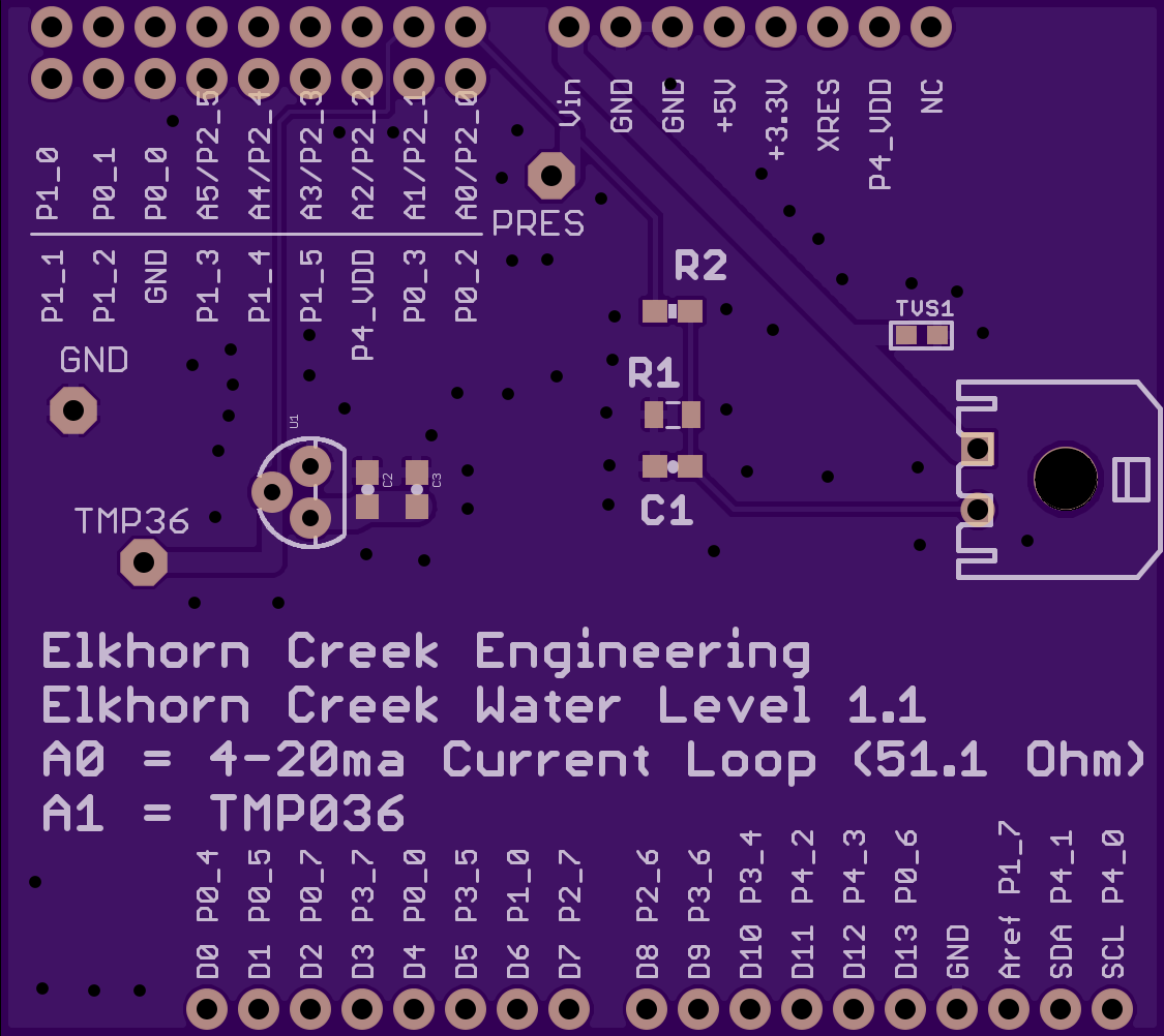
Once I completed the layout I sent the board to OSH Park to be manufactured.  I have shared the project on their website.  OSH Park is an excellent company that is easy to do business with.  They charged me $22.55 for three of the boards.  The fit and finish of the boards is very nice.  Here is the board:

creekboard1.1

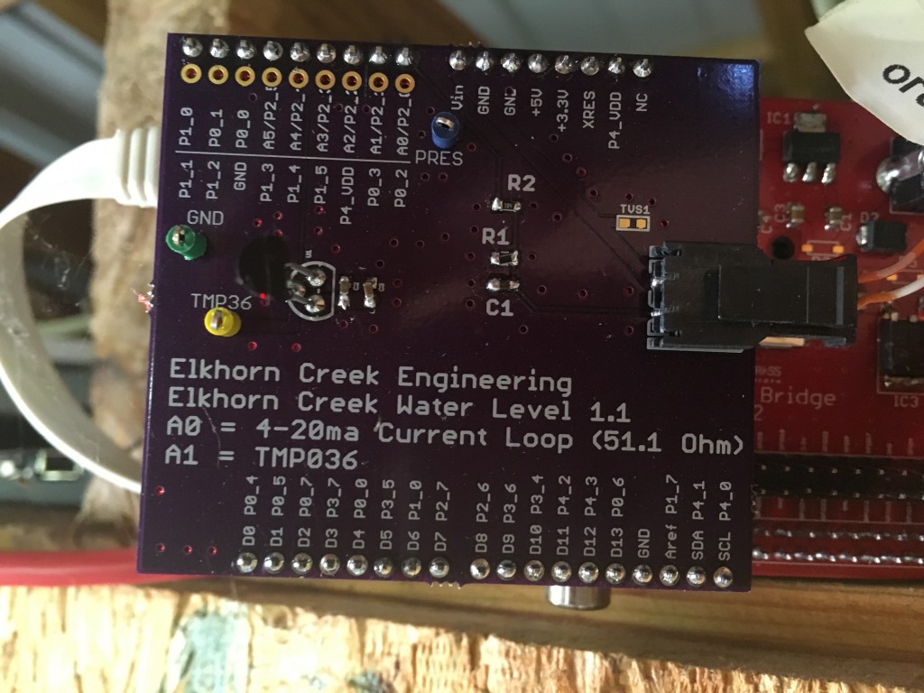
Here is the assembled board:


IMG_2652

I have posted all of the project files at github.  You can “git” them from https://github.com/iotexpert/TheCreek  The Eagle project is in the CreekBoard directory.

Index Description
The Creek: IOT for the Elkhorn Creek Introduction
The Creek: Solution Architecture 1.0 Overall architecture
The Creek: Creek Board 1.1 Eagle layout of the board
The Creek: Creek Board 1.0 – RCCA A discussion of the errors in the 1.0 board
The Creek: CYPI, a Raspberry Pi to Arduino Bridge PSoC4 <--> Raspberry Pi Bridge Board
The Creek: PSoC4 Creator Schematic and Firmware Firmware to interface with the temperature and pressure sensors
The Creek: Testing the Firmware Using tools to verify that the PSoC 4 Firmware is working correctly
The Creek: Testing the Bootloader Make sure that you can load new firmware into the PSoC
The Creek: Software Architecture All of the Raspberry Pi software connections
The Creek: Install MySql Instruction to configure MySql
The Creek: Install Tomcat Instruction to configure Tomcat JSP Server
The Creek: Data Collection Java (Part 1) The Java program that reads the I2C and saves it in the database
The Creek: Data Collection Java (Part 2) The Java program that reads the I2C and saves it in the database
The Creek: Create the Chart with JFreeChart Using open source Java charting software to create plots of the Creek Depth
The Creek: Flood Event Data Processor A batch program to create analyze the database and create a table of flood events
The Creek: Flood Event Web Page A batch program to create the flood event web page
The Creek: Creek Server 1.1 Updates to all of the back off server programs to integrate charts
The Creek: JSP Web Page for www.elkhorn-creek.org The JSP program to make the table and display the website
The Creek: Raspberry Pi Clock Stretching Sorting out a bug in the system having to do with the Broadcomm Raspberry Pi Master not functioning well with clock stretching
The Creek: Creek Server 1.2 Caching the web pages to make them faster