Summary
This article updates the Tilt Hydrometer project to include an LCD display using the Segger emWin library. This includes a discussion of a “new” library in the suite of IoT Expert awesome sauce. Specifically the IoT Expert Graphics library.
This series is broken up into the following 12 articles with a few additional possible articles.
Tilt Hydrometer (Part 1) Overview & Out-of-Box
Tilt Hydrometer (Part 2) Architecture
Tilt Hydrometer (Part 3) Advertising Scanner
Tilt Hydrometer (Part 4) Advertising Packet Error?
Tilt Hydrometer (Part 5) Tilt Simulator & Multi Advertising iBeacons
Tilt Hydrometer (Part 6) Tilt Simulator an Upgrade
Tilt Hydrometer (Part 7) Advertising Database
Tilt Hydrometer (Part 8) Read the Database
Tilt Hydrometer (Part 9) An LCD Display
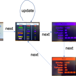
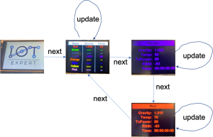
Tilt Hydrometer (Part 10) The Display State Machine
Tilt Hydrometer (Part 11) Draw the Display Screens
Tilt Hydrometer (Part 12) CapSense
Tilt Hydrometer: LittleFS & SPI Flash (Part ?)
Tilt Hydrometer: WiFi Introducer (Part ?)
Tilt Hydrometer: WebServer (Part ?)
Tilt Hydrometer: Amazon MQTT (Part ?)
Tilt Hydrometer: Printed Circuit Board (Part ?)
You can get the source code from git@github.com:iotexpert/Tilt2.git This repository has tags for each of the articles which can be accessed with "git checkout part12" You can find the Tilt Simulator at git@github.com:iotexpert/TiltSimulator.git.
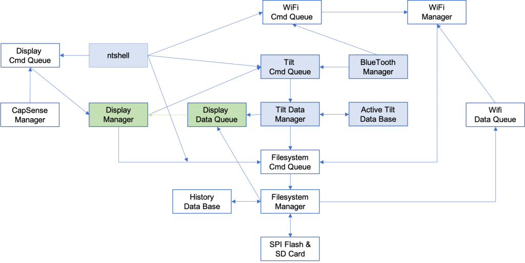
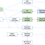
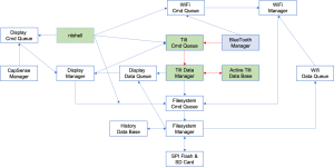
Here is the architecture with the blocks we are editing marked green.
Story
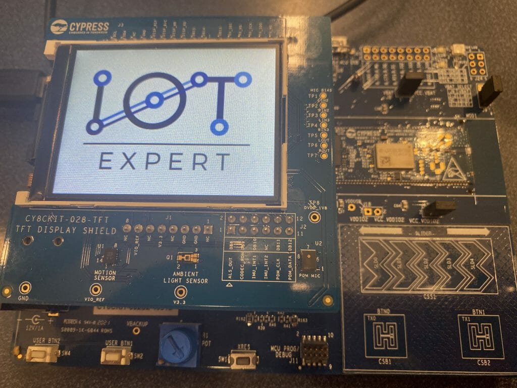
I knew that I wanted to use the TFT Display so that I could have this Tilt Hydrometer system sitting in my “brewery”. Notice in the picture below you can see that the screen is currently displaying the data from the “black” tilt. Also notice that you can see two fermenters in the background in the brewery. Who needs a guest bathroom in the era of Covid 🙂
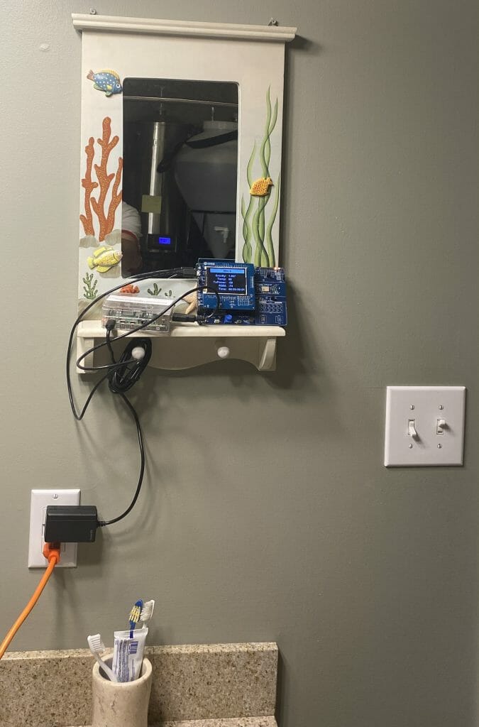
Also notice that there is a Raspberry Pi (more on that in a future article). And for all of you married people out there, yes I have a very frustrated but forgiving wife.
Add Display Libraries & Fix the Makefile
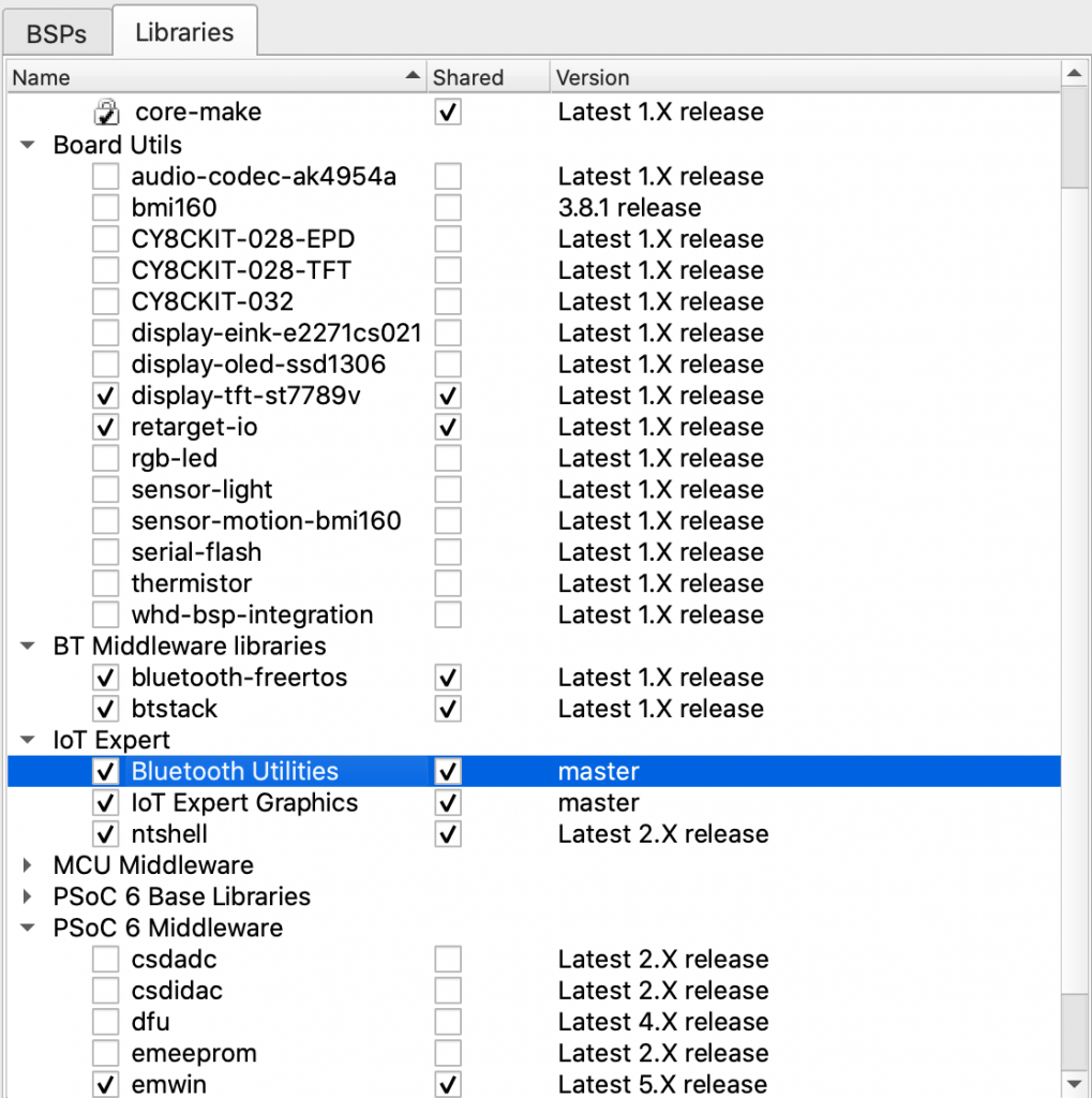
The first step in building this is to add the new libraries. Specifically the display-tft-st7789v library which knows how to talk to the lcd and the emWin library. AND the new IoT Expert Graphics Library.
In order to use the emWin library you need to fix the Makefile to include the emWin component. Notice that I chose OS meaning an RTOS and NTS meaning no touch screen.
COMPONENTS=FREERTOS WICED_BLE EMWIN_OSNTS
IoT Expert Graphics Library
I wanted to have a splash screen on this project with my Logo. So I started digging around on my computer to find the graphics, which I found in the file IOTexpert_Logo_Vertical.png. Unfortunately this is a 1091×739 portable network graphics file, not exactly what emWin wants to draw with. To fix this I opened it in GIMP
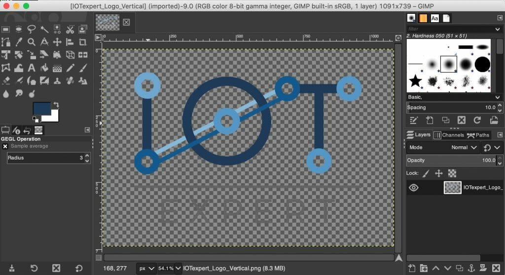
Then I resized it to my screen size (320×240)
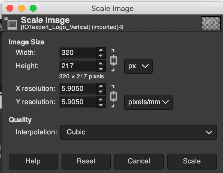
Now it looks like this:
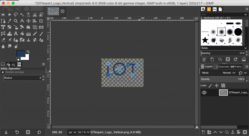
Then I saved it as a PNG. Still doesn’t work with emWin. But, if you look in the emWin library you will notice that there is a new directory called “Tool”
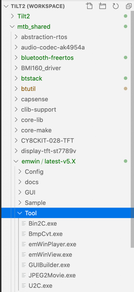
This directory contains the Segger tools for supporting their graphics library. The one that I want is called “Bin2C.exe” (unfortunately it is a Windows only tool). I run it and open the logo.
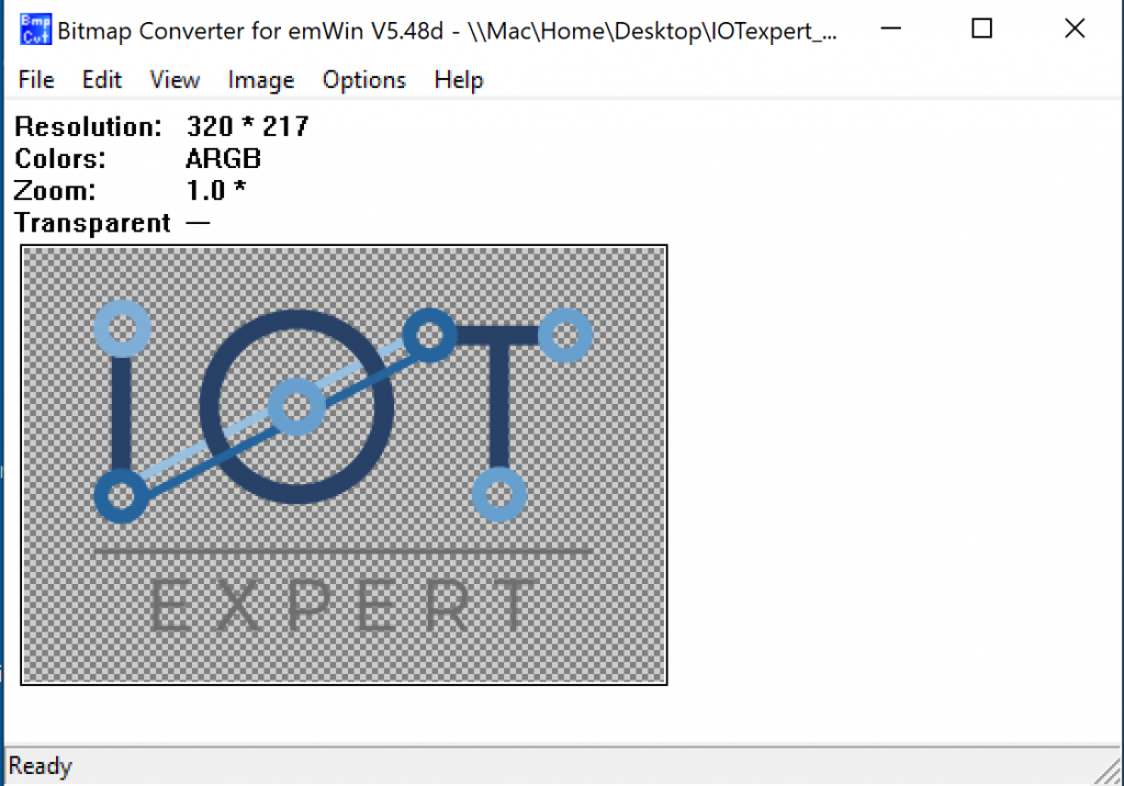
Then I click save and pick “C” bitmap file (*.c)
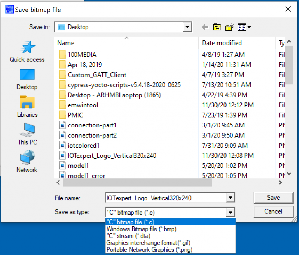
For my display I am using 16-bit color, also known as High Color with Alpha 565.

The tool nicely makes me a file with the right stuff in it. First, the array of unsigned char (representing the bitmap) and the GUI_BITMAP structure.
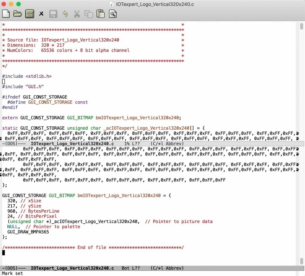
Unfortunately it didn’t create a header file which I do like this (notice I renamed the data)
#pragma once
#include <stdlib.h>

#include "GUI.h"

extern GUI_CONST_STORAGE GUI_BITMAP bmIOTexpert_Logo_Vertical320x240;
And, if you have been paying attention you might have noticed that I created a new IoT Expert Library – Graphics that contains these new files. (I have explained this process several times in the past)
TFT Pins Discussion
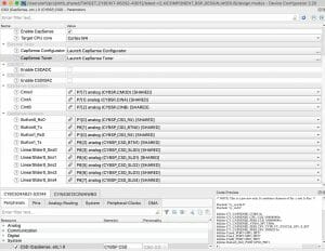
I am planning on making a custom circuit board for this whole project. So, I didn’t want to use the whole CY8CKIT-028-TFT library. In order to start the TFT you need to call the function “mtb_st7789v()” with an argument of type “mtb_st7789v_pins_t”. When Cypress created the BSP for the TFT we defined a function like this in the header file.
/**
 * Initializes GPIOs for the software i8080 interface.
 * @return CY_RSLT_SUCCESS if successfully initialized, else an error about
 * what went wrong
 */
static inline cy_rslt_t cy_tft_io_init(void)
{
    static const mtb_st7789v_pins_t PINS =
    {
        .db08 = CY8CKIT_028_TFT_PIN_DISPLAY_DB8,
        .db09 = CY8CKIT_028_TFT_PIN_DISPLAY_DB9,
        .db10 = CY8CKIT_028_TFT_PIN_DISPLAY_DB10,
        .db11 = CY8CKIT_028_TFT_PIN_DISPLAY_DB11,
        .db12 = CY8CKIT_028_TFT_PIN_DISPLAY_DB12,
        .db13 = CY8CKIT_028_TFT_PIN_DISPLAY_DB13,
        .db14 = CY8CKIT_028_TFT_PIN_DISPLAY_DB14,
        .db15 = CY8CKIT_028_TFT_PIN_DISPLAY_DB15,
        .nrd = CY8CKIT_028_TFT_PIN_DISPLAY_NRD,
        .nwr = CY8CKIT_028_TFT_PIN_DISPLAY_NWR,
        .dc = CY8CKIT_028_TFT_PIN_DISPLAY_DC,
        .rst = CY8CKIT_028_TFT_PIN_DISPLAY_RST,
    };
    return mtb_st7789v_init8(&PINS);
}
Curiously we also made a static definition inside of the .c file.
static const mtb_st7789v_pins_t tft_pins =
{
    .db08 = CY8CKIT_028_TFT_PIN_DISPLAY_DB8,
    .db09 = CY8CKIT_028_TFT_PIN_DISPLAY_DB9,
    .db10 = CY8CKIT_028_TFT_PIN_DISPLAY_DB10,
    .db11 = CY8CKIT_028_TFT_PIN_DISPLAY_DB11,
    .db12 = CY8CKIT_028_TFT_PIN_DISPLAY_DB12,
    .db13 = CY8CKIT_028_TFT_PIN_DISPLAY_DB13,
    .db14 = CY8CKIT_028_TFT_PIN_DISPLAY_DB14,
    .db15 = CY8CKIT_028_TFT_PIN_DISPLAY_DB15,
    .nrd = CY8CKIT_028_TFT_PIN_DISPLAY_NRD,
    .nwr = CY8CKIT_028_TFT_PIN_DISPLAY_NWR,
    .dc = CY8CKIT_028_TFT_PIN_DISPLAY_DC,
    .rst = CY8CKIT_028_TFT_PIN_DISPLAY_RST,
};
What I know is that I need those pin definitions, so I will copy them into my project (a bit later in this article)
Make a New Display Task
To get this going, make a file called displayManager.h to contain the public definition of the task.
#pragma once

void dm_task(void *arg);
Then add a file displayManager.c. This file will be the focus of the rest of this article. Before we get too far down the road building all of the functionality of the display, first lets setup a test task to verify the functionality of the libraries and the screen. As I talked about earlier, define the pins for the driver. These the pin names come out of the BSP and “should” work for all of the Cypress development kits (that have Arduino headers).
#include <stdio.h>
#include <stdlib.h>

#include "GUI.h"
#include "mtb_st7789v.h"
#include "cybsp.h"

#include "FreeRTOS.h"
#include "task.h"

#include "displayManager.h"

#include "IOTexpert_Logo_Vertical320x240.h"

const mtb_st7789v_pins_t tft_pins =
{
    .db08 = (CYBSP_J2_2),
    .db09 = (CYBSP_J2_4),
    .db10 = (CYBSP_J2_6),
    .db11 = (CYBSP_J2_10),
    .db12 = (CYBSP_J2_12),
    .db13 = (CYBSP_D7),
    .db14 = (CYBSP_D8),
    .db15 = (CYBSP_D9),
    .nrd  = (CYBSP_D10),
    .nwr  = (CYBSP_D11),
    .dc   = (CYBSP_D12),
    .rst  = (CYBSP_D13)
};
Then make a simple task that
- Initializes the driver
- Initialize emWin
- Sets the background color
- Clear the screen
- Draw the IoT Expert Logo
void dm_task(void *arg)
{
    /* Initialize the display controller */
    mtb_st7789v_init8(&tft_pins);
    GUI_Init();
    GUI_SetBkColor(GUI_WHITE);
    GUI_Clear();
    GUI_DrawBitmap(&bmIOTexpert_Logo_Vertical320x240,0,11);

    while(1)
        vTaskDelay(portMAX_DELAY);
}
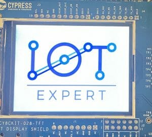
Test
When I program this project I get a nice white background screen with my beautiful logo on it. Sweet. In the next article I’ll do some work on displaying useful information on the screen.
No comment yet, add your voice below!