Summary
Hello everyone. This is lesson 0 of a series of 7 lessons about creating an IoT application using the Infineon ModusToolbox Software Environment to create a WiFi enabled drone. In the next two hours we will build a remote control that uses the PSoC 6 MCU, WiFi, MQTT, CapSense and a 3-D Magnetic Joystick. Then we will build the drone which will use a PSoC 6, WiFi, MQTT, CapSense and a BLDC motor controller.
What I will do today is take you lesson by lesson through the class and talk about how it all works and what you need to do. When I built the class it was absolutely my goal to have every button click and line of code described. That being said, it is likely that I made some errors. So, during the class you will be able to send messages to my team who will answer the questions, or ask me and I’ll answer live. If you missed the class, that’s OK, you will be able to watch it on replay. In addition if you have a question after the live stream is over, leave a comment here and I’ll answer.
I will attempt to go slowly enough for you to follow along, but if I go to fast, don’t worry you should be able to follow along with the instructions on this website.
Every lesson will have this table in it and you will be able to click to follow along with the different lessons.
Embedded World 2021 - Infineon ModusToolbox PSoC 6 Drone
#
Description
0
Introduction & Resources
1
FreeRTOS & CapSense
2
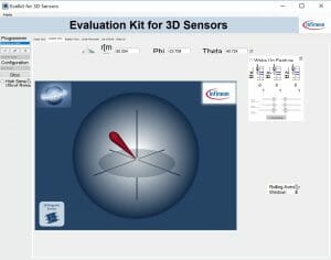
3-D Magnetic Sensing XENSIV Joystick
3
WiFi
4
MQTT
5
Low Power
6
BLDC Motor Control
7
WS2812 Strip LEDs
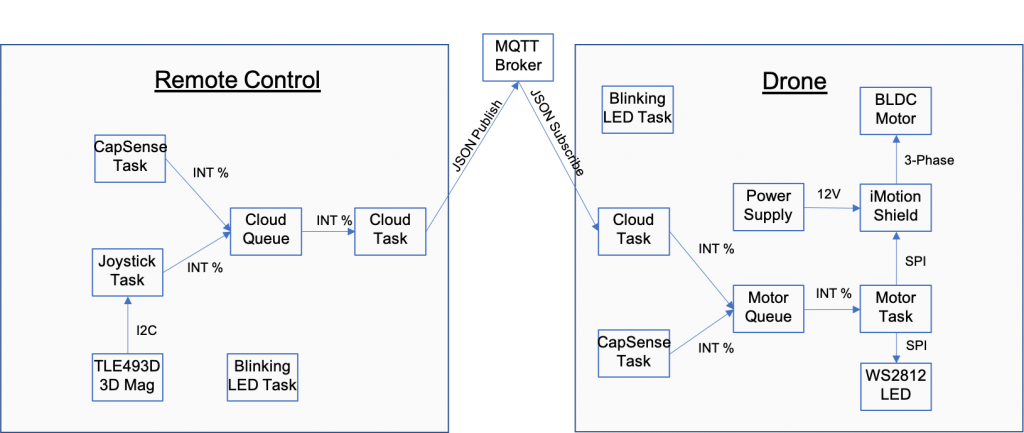
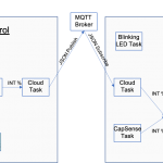
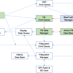
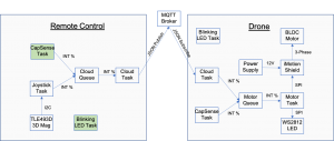
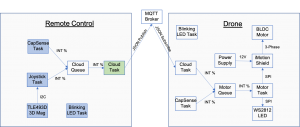
Here is the overall system architecture:
The Remote Control
The remote control is built with two Infineon development boards
| Kit | Features |
|---|---|
| CY8CPROTO-062-4343W | PSoC 6,CYW4343W WiFi Bluetooth Combo Radio,CapSense |
| TLE493D-W2B6 | XENSIV 3-D Magnetic Sensor |
Here are some pictures.
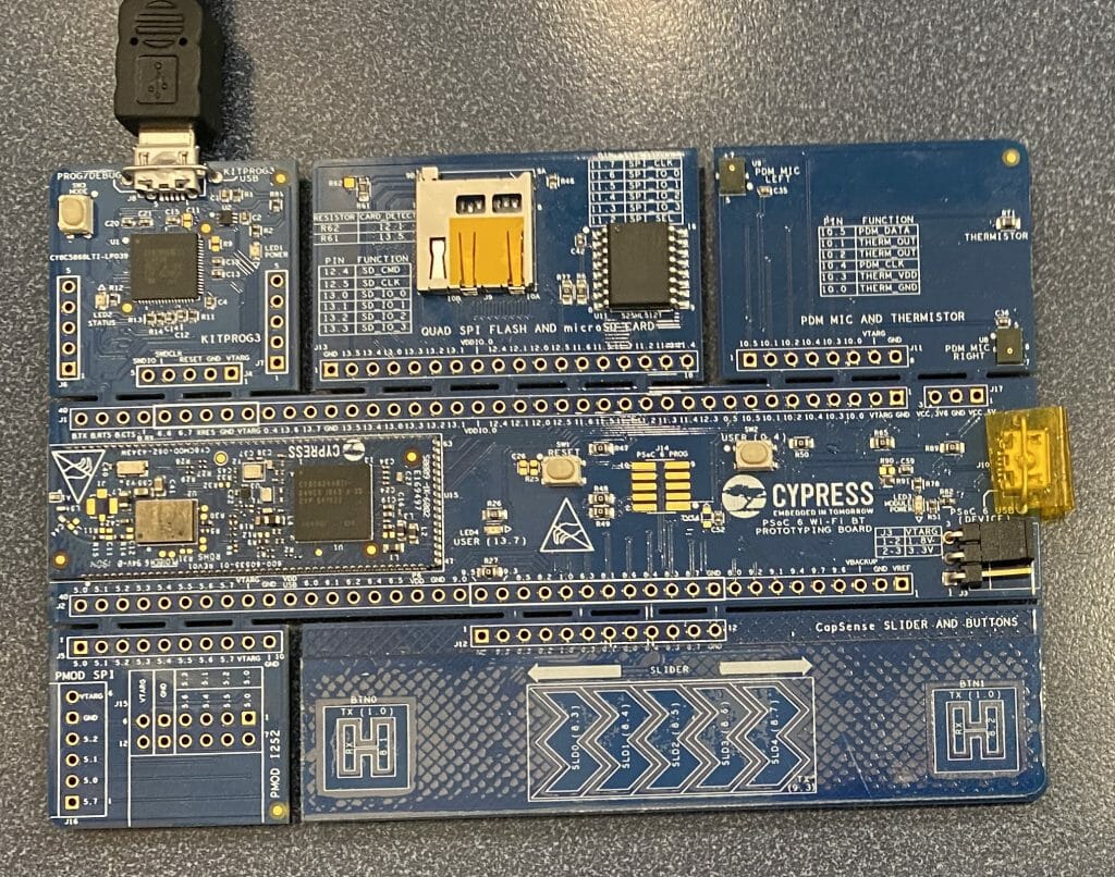
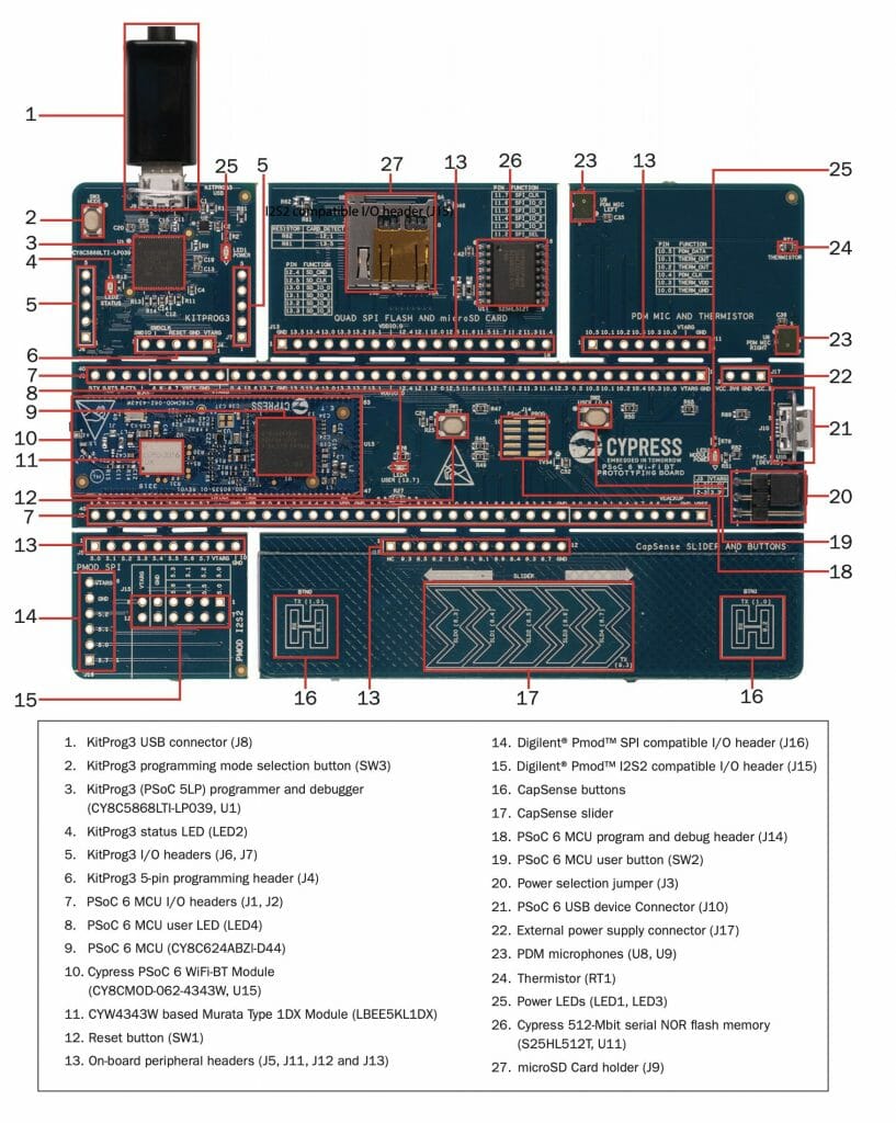
CY8CPROTO-062-4343W. The top left of the board is a KitProg programmer. The middle third on the left is the 4343W and the PSoC 6. The bottom right are the CapSense buttons. Just to the right of the programmer is a SD Card holder and S512FL Quad SPI Flash.
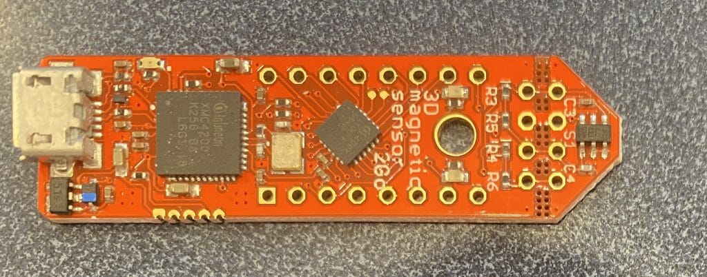
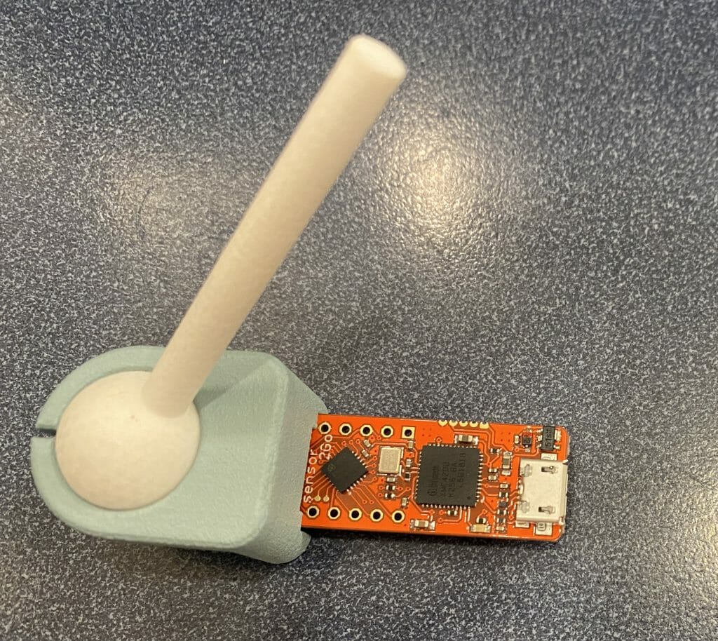
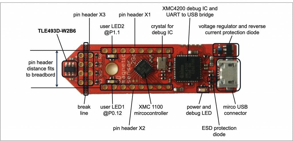
This the the top of the TLE-493D-W2B6 3-D magnetic sensor board. On the far right, the tiny 6 pin chip is the actual sensor. The big hole to the left of the sensor is to mount a magnet. The two chips on the left are used as a bridge to USB (if you are developing). I attach to this device using the I2C interface pins.
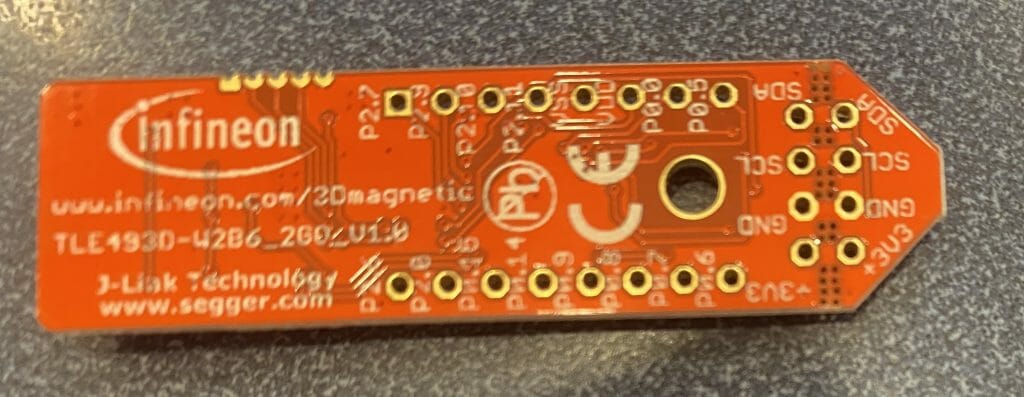
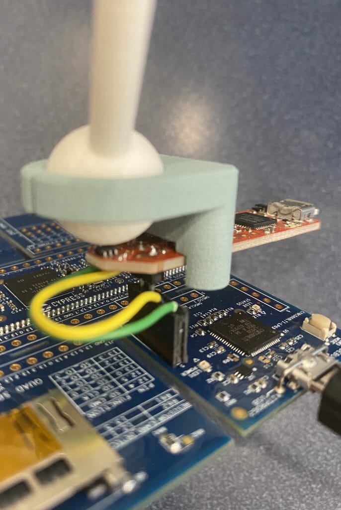
Here is the back where you can see the SCL, SDA, Power and Ground labeled. Unfortunately, they are in the wrong order to plug directly into the PSoC kit so Greg had to make a little wire switcher.
Here is the board with the really really cool 3-d printed joystick. Simply two pieces of plastic with a magnet in the bottom.
This picture show how the magnetic sense board is mounted onto the kit
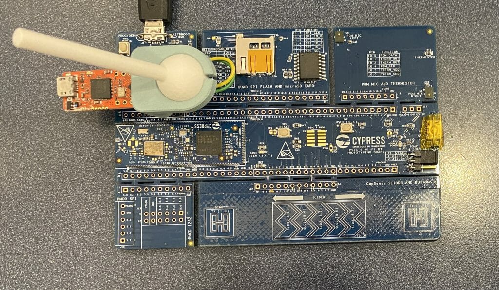
Here is the whole thing assembled.
The Crazy Drone
The drone was built with
| Kit | Features |
|---|---|
| CY8CKIT-062S2-43012 | PSoC 6 + CYW43012 Low Power Bluetooth WiFI Combo |
| TLE9879WXA40 | BLDC Control Shield |
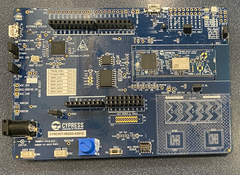
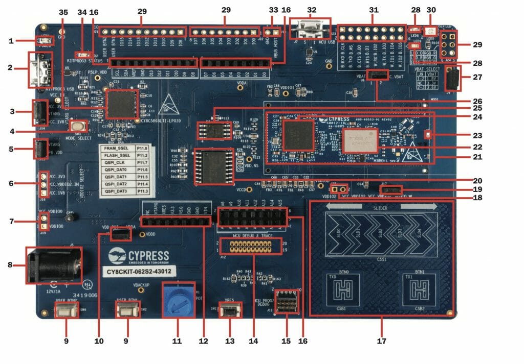
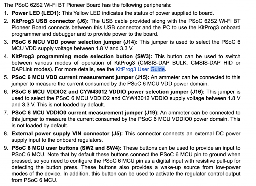
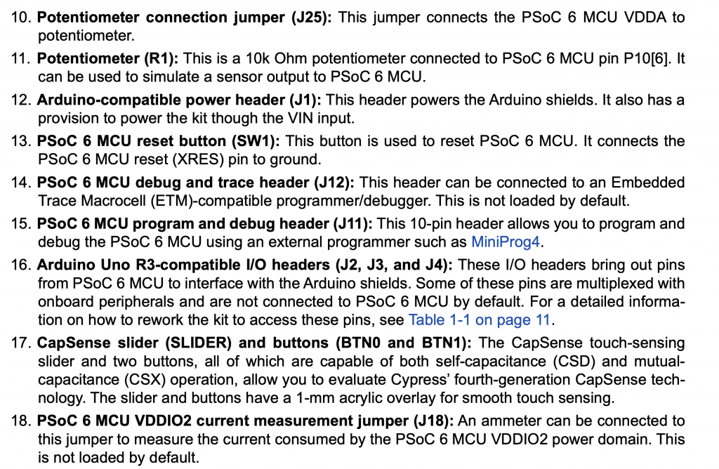
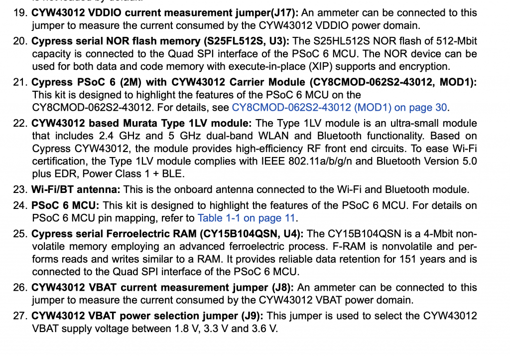
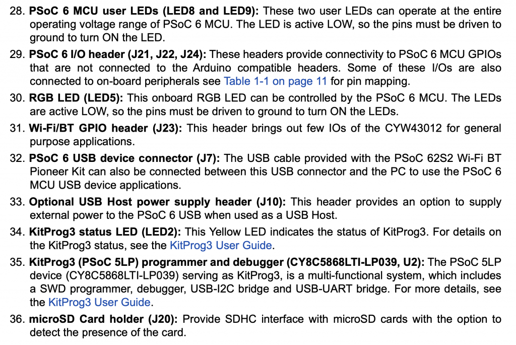
Here is a picture of the CY8CKIT-062S2-43012. On the far right in the middle is the PSoC 6 and CYW43012. In the lower right are the CapSense Buttons and Slider. The KitProg IC is just below the top Arduino Header.
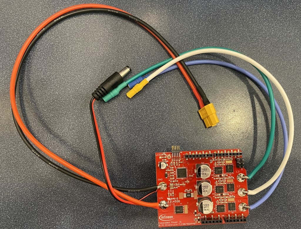
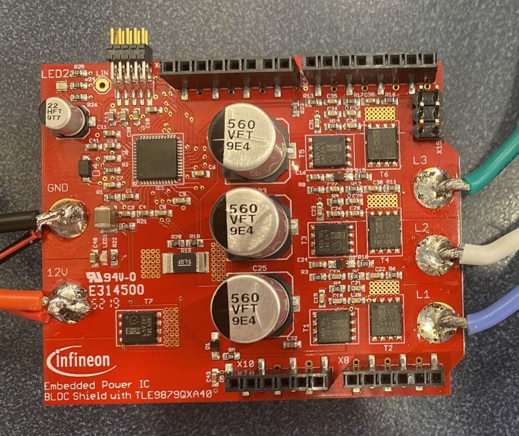
In order to drive the BLDC motor I use the TLE9879WXA40 Motor Shield. This has everything needed to do Field Oriented Control of a 3-phase BLDC motor. The Blue, Green and White wires are the 3-phases of the BLDC. The Red and Black are simply +12V and Ground. You interface from the PSoC to the BLDC shield via a SPI interface (attached to the Arduino pins).
The BLDC motor is mounted into a 3-d printed holder. The mount is attached to hollow carbon fiber tubes that run on bearings that you see below. The wires run down through the tubes.
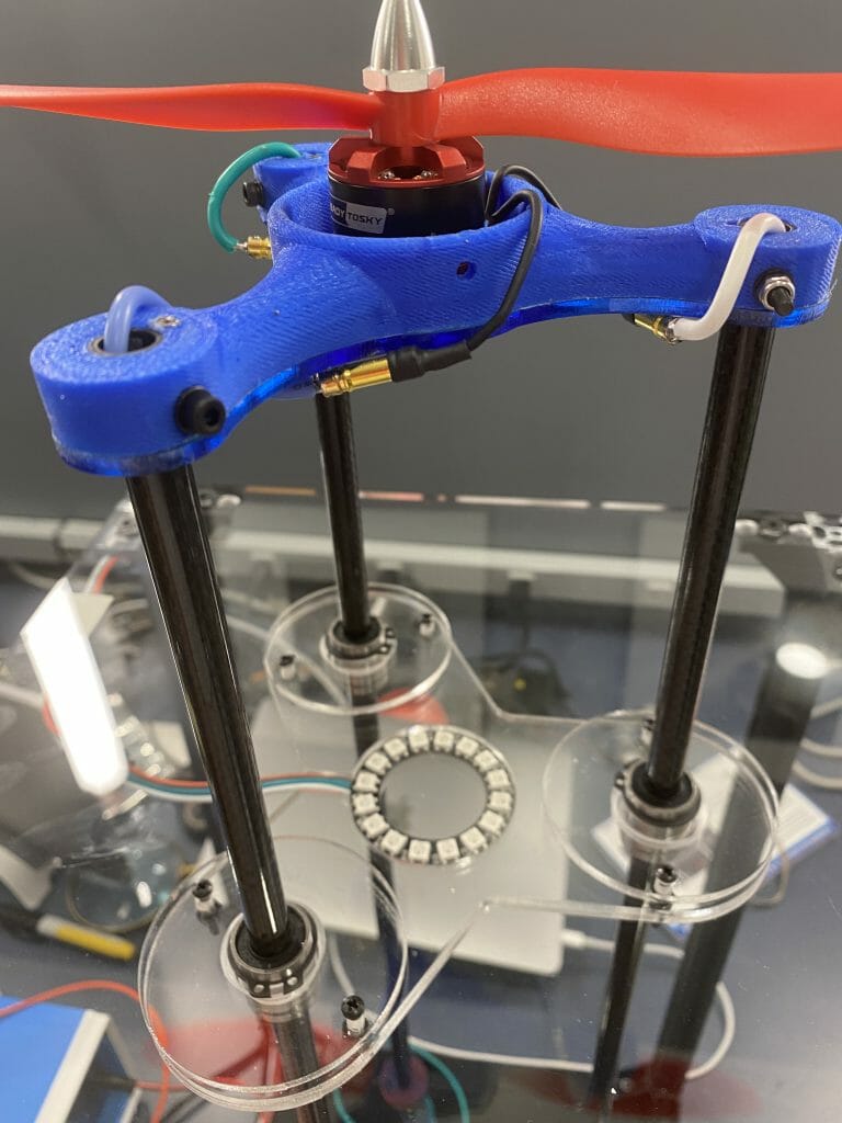
At the bottom, the blue box just provides +12v to the drone and the PSoC board.
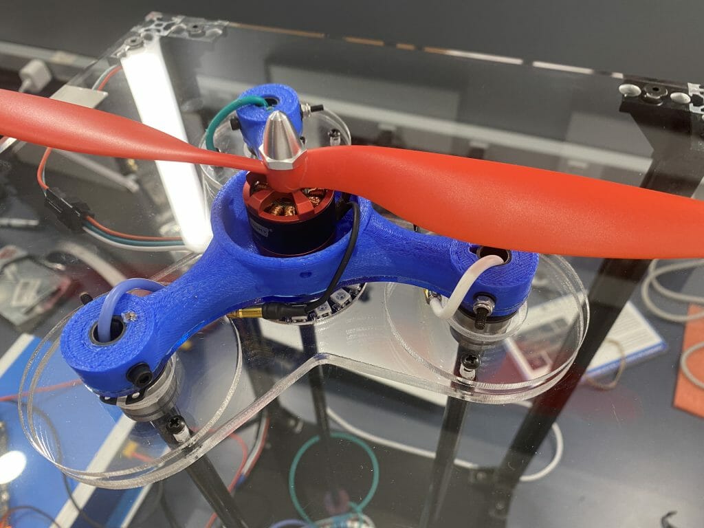
Here is a closer picture of the BLDC motor.
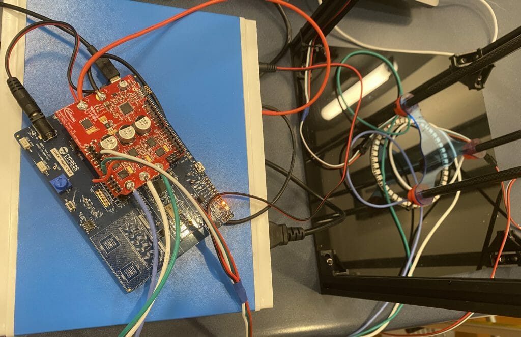
Here is a picture of the whole crazy thing running. If you look in the background you can see a top secret new PSoC motor controller. Is that an Easter egg?
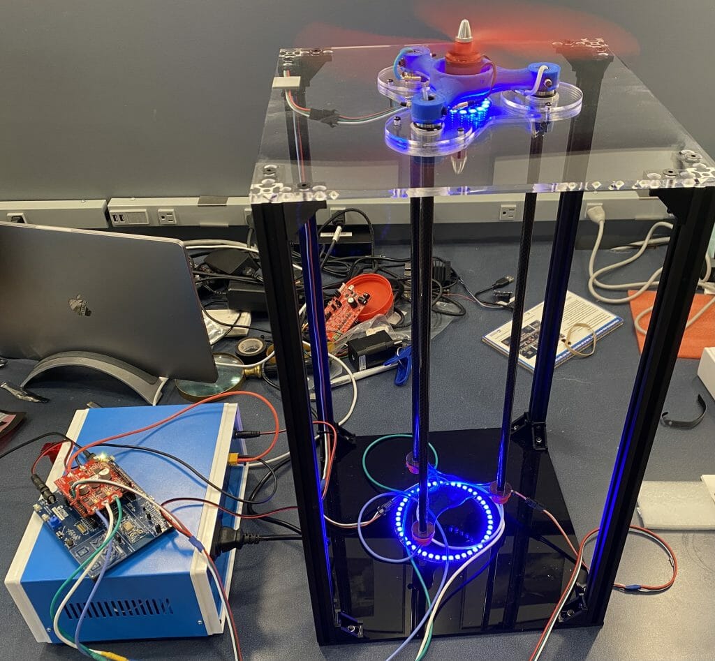
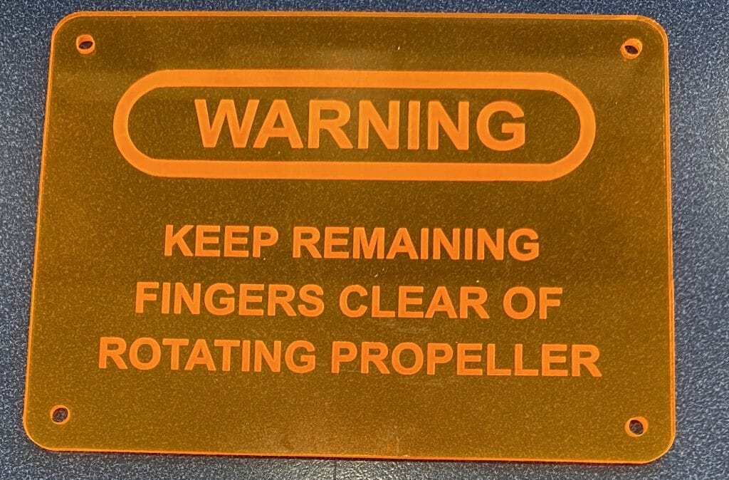
And yes, it will cut your fingers off if you aren’t careful.
Resources
You will need a few things for this class:
- ModusToolbox Software Environment
- PSoC 6 WiFi-BT Prototyping Kit (CY8CPROTO-062-4343W)
- (optional) PSoC 62S2 WiFi-BT Pioneer Kit (CY8CKIT-062S2-43012)
- (optional) XENSIV TLE493D-W2B6 MS2GO and JOYSTICK FOR 3D 2 GO KIT
- (optional) BLDC SHIELD TLE9879TOBO1
- (optional) Readytosky 2212 920KV Brushless Motors and Readytosky 10×4.5 1045 Propeller
ModusToolbox Software Environment
You can download Modus Toolbox from here

CY8CPROTO-062-4343W
You can read all about this development kit on the website or in the KitGuide
CY8CKIT-062S2-43012
You can read all about this development kit on the website or in the KitGuide
TLE9879QXA40 BLDC Motor Controller
You can read all about this development kit on the website or in the KitGuide
XENSIV TLE493D
You can read all about this development kit on the website or in the KitGuide
2 Comments
Hi Alan,
Thank u again for the awesome content! I am now following your step-by-step instructions to recreate the projects.
Just to highlight that the P/N for the XENSIV+XMC MCU board is TLE493D-W2B6 MS2GO (correctly mentioned at the Resources section), whereas the P/N for the XENSIV sensor is TLE493D-W2B6 Ax. There was some mix-up when I ordered thru ISR before so I highlight here to ALL. Hope this helps!
Harris
Hi Alan,
I would further elaborate that “At the bottom, the blue box provides +12v to the drone and the PSoC board (if USB is not connected), also provides +5V to the LED strips.”
Just my 2-cents.
Harris