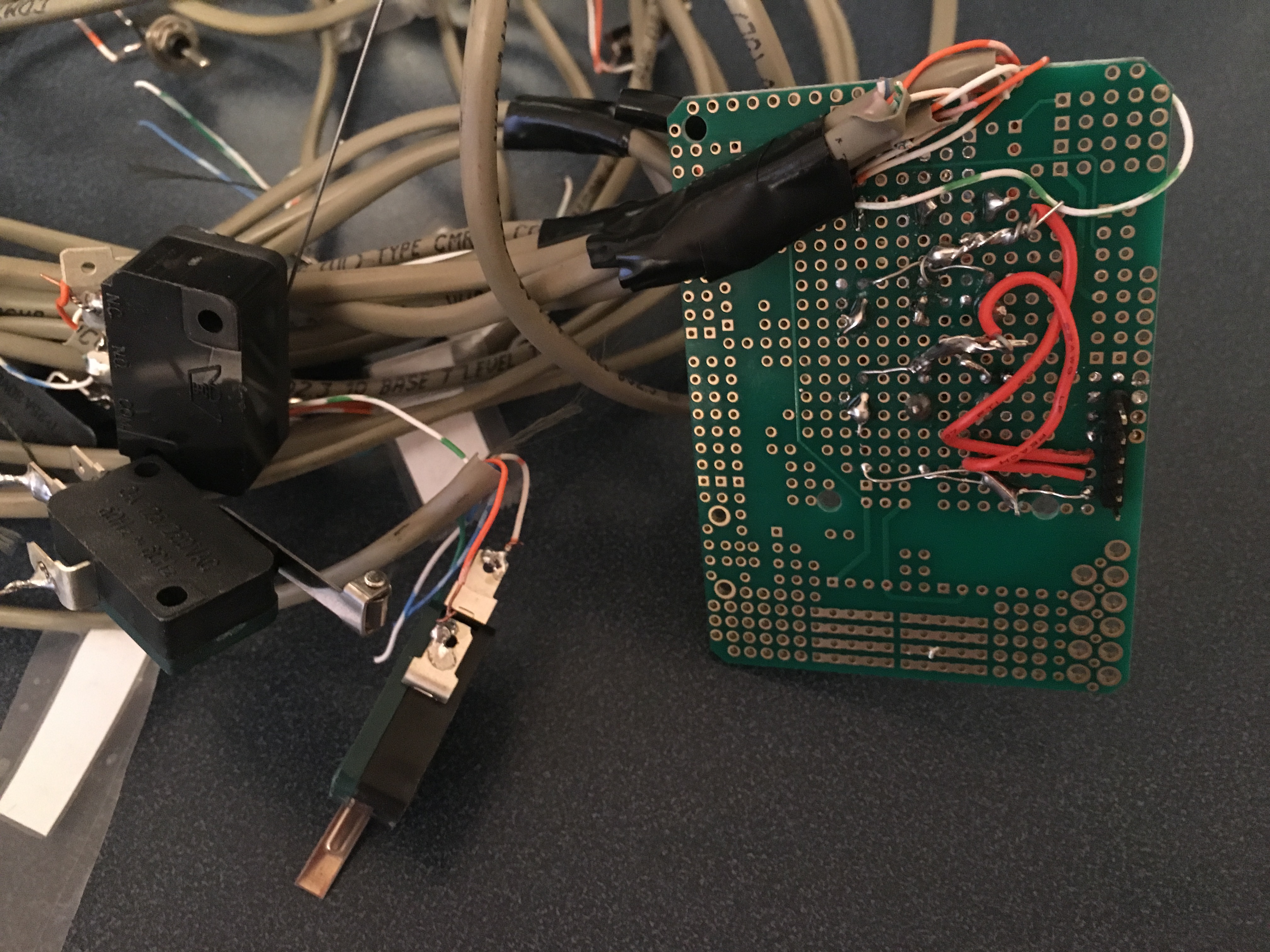
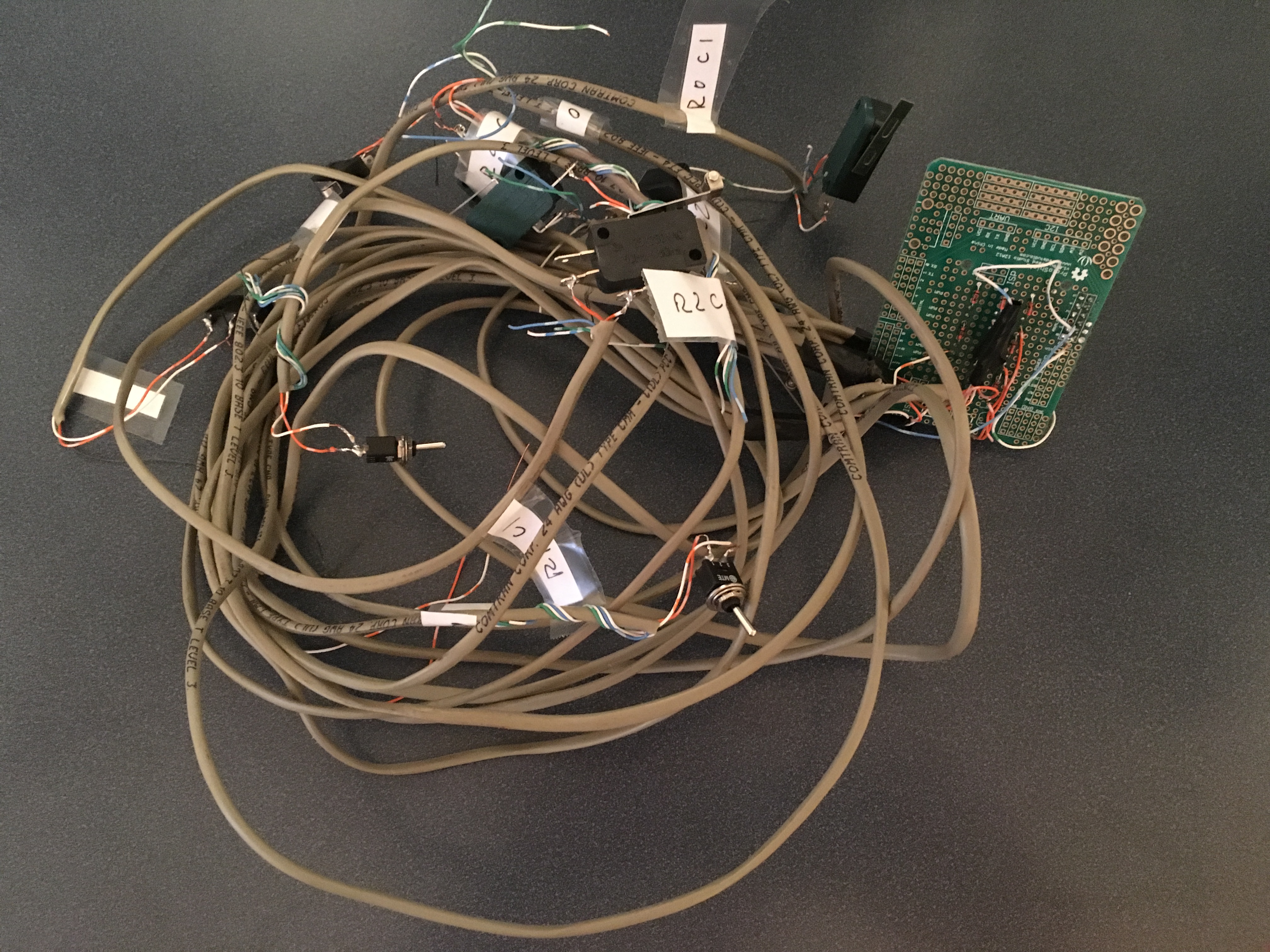
I got the boards back and assembled several of them… and they do not work. It has been a really really frustrating few days trying to figure out what was going on. I started with the assumption that I had a soldering problem so I soldered it and resoldered it about 10 times. I used the soldering iron, I used hot-air, I reflow’ed the board, and I did 3 different complete board re-dos. None worked. I really wanted this to work before Maker Faire.
Finally I gave up and sent my board to our kit team in India. This is not such a simple thing to do as you need to have commercial invoices for all of the stuff that I sent them… after getting it rolling and patiently waiting for three days for Fed-Ex to get it through all of the customs hoops etc. I get this email from the Kit Manager:
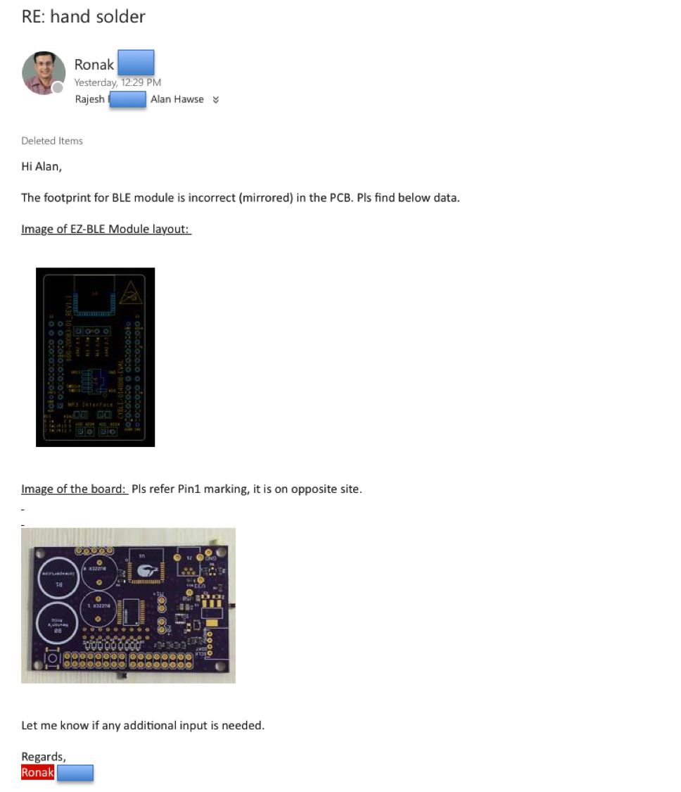
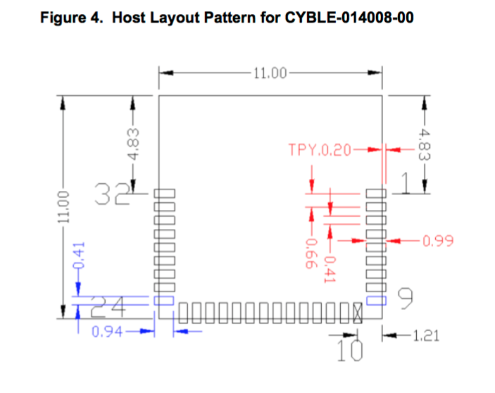
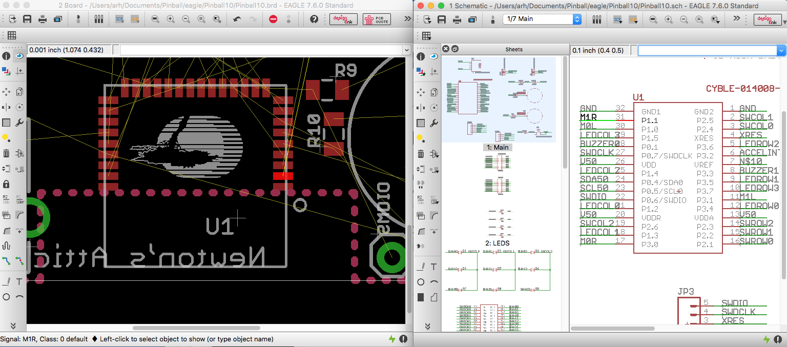
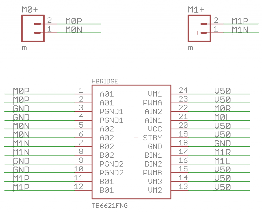
Damn damn damn… I know that I double checked the package. That is such an amateur mistake… alway always always check your footprints. But Ronak is right, here is a screen shot of the Eagle Layout which I clicked on Pin 2. (I rotate the image to make it line up with the data sheet)
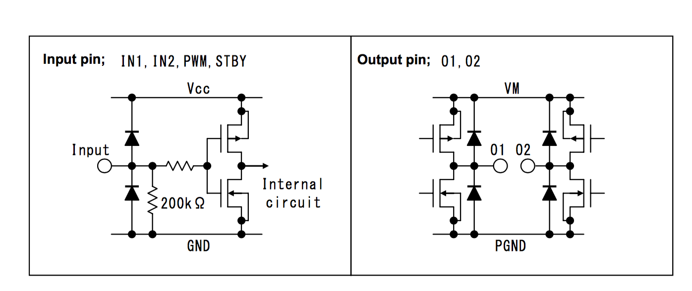
And it matches the the picture from the data sheet for the module… However… notice that it says “Bottom View” which means I flipped it.
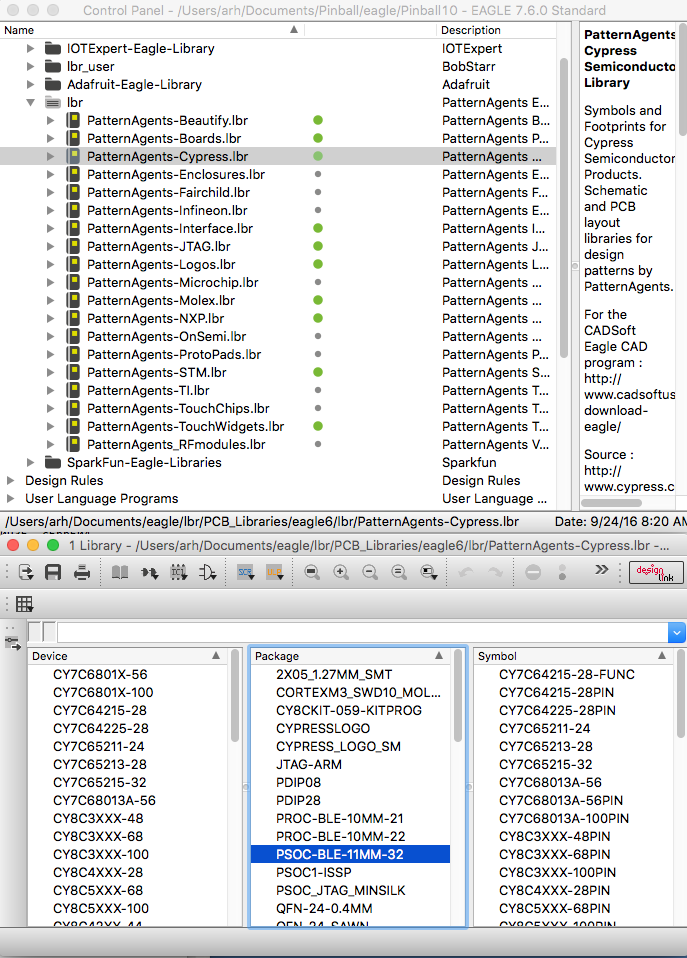
Here is a screenshot of the package in the eagle library… sure enough. It is flipped.
More evidence, here is the top view:
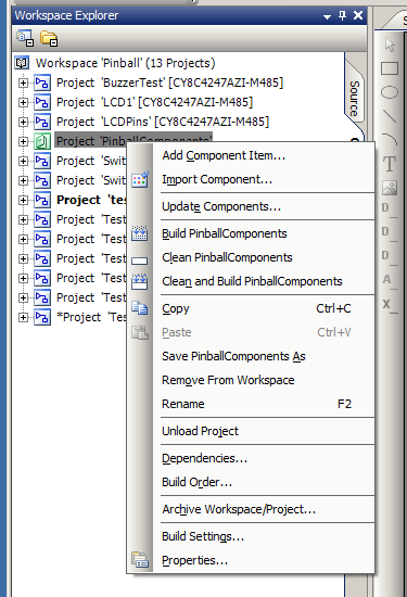
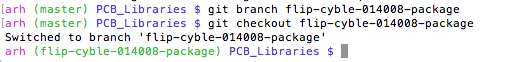
So, I need to fix the package and then re-do the layout. I start this process by making a new branch in git.
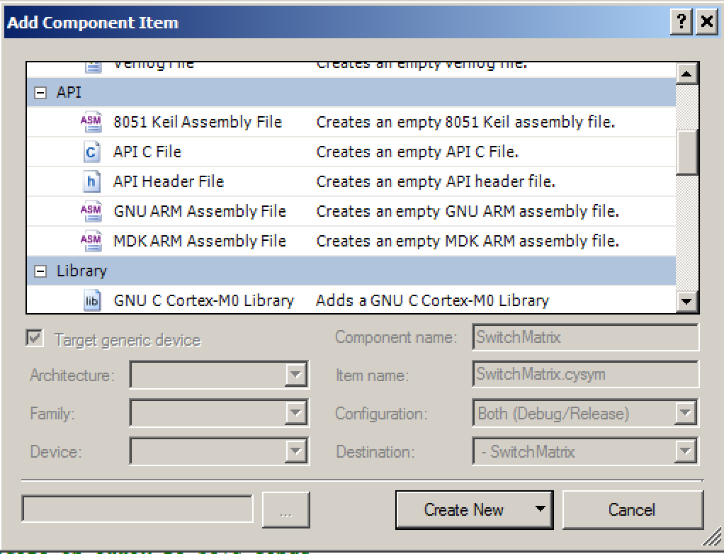
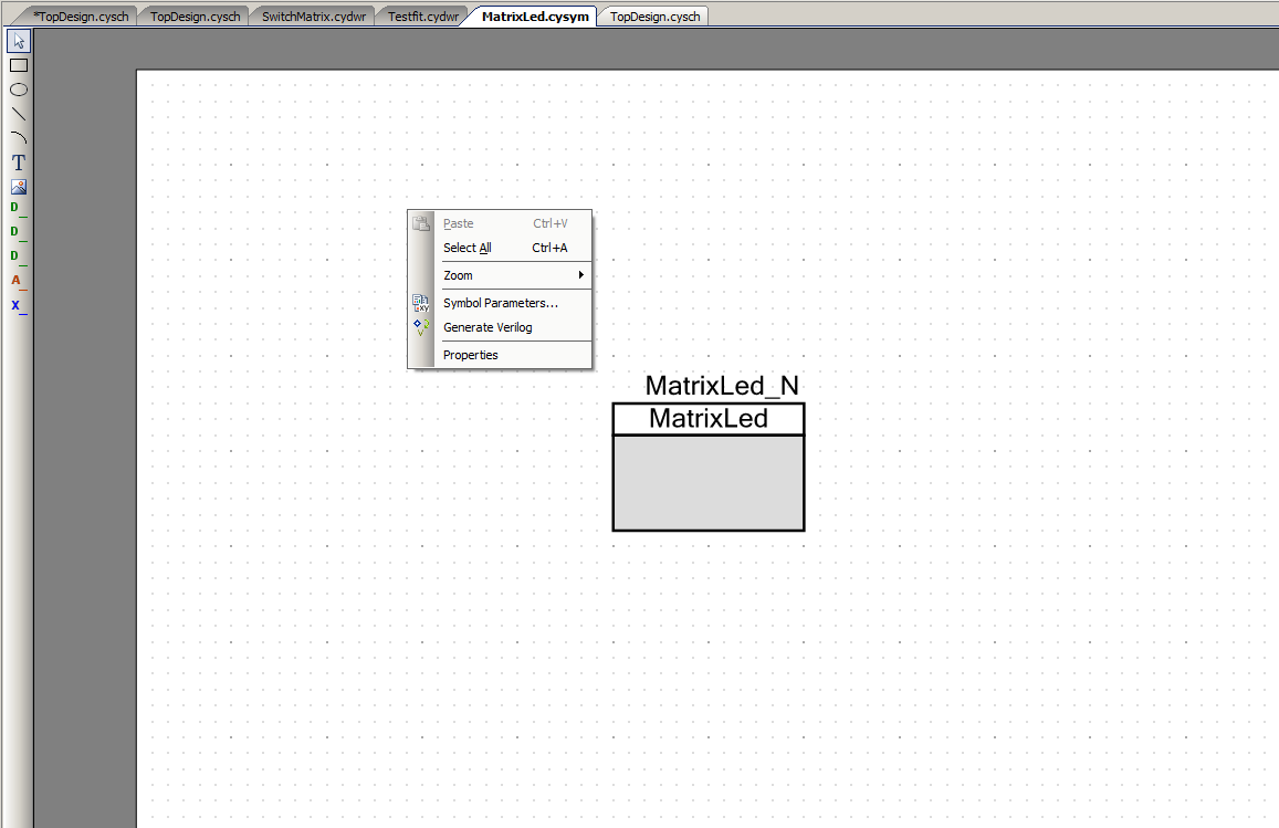
Then open the library and the package:
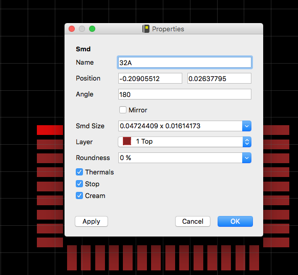
To make things easier I turn off all of the layers except for Top. This allows me to easily click on each pad. One thing that is a bit of a PITA is that you have to change of all of the pads to something else before you can change each one to what you want e.g. you can’t rename the pad currently named 1 to be 32 because there is already a 32. So, what I do is rename each pad to the new name with an A on the end (see the image below). Once that is done I go back around and remove the “A”s.
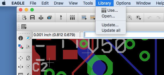
Once my package is fixed, I update the library that I am using in my layout.
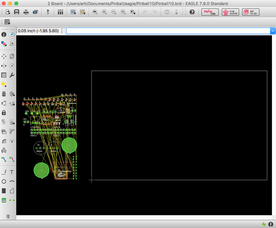
Eagle immediately tells me that I have a problem… which is true, so true.

Then I ripup all of the nets, which is so sad. The problem is that all of the things I had on the left are now on the right and visa-versa so I need to think about the whole placement.
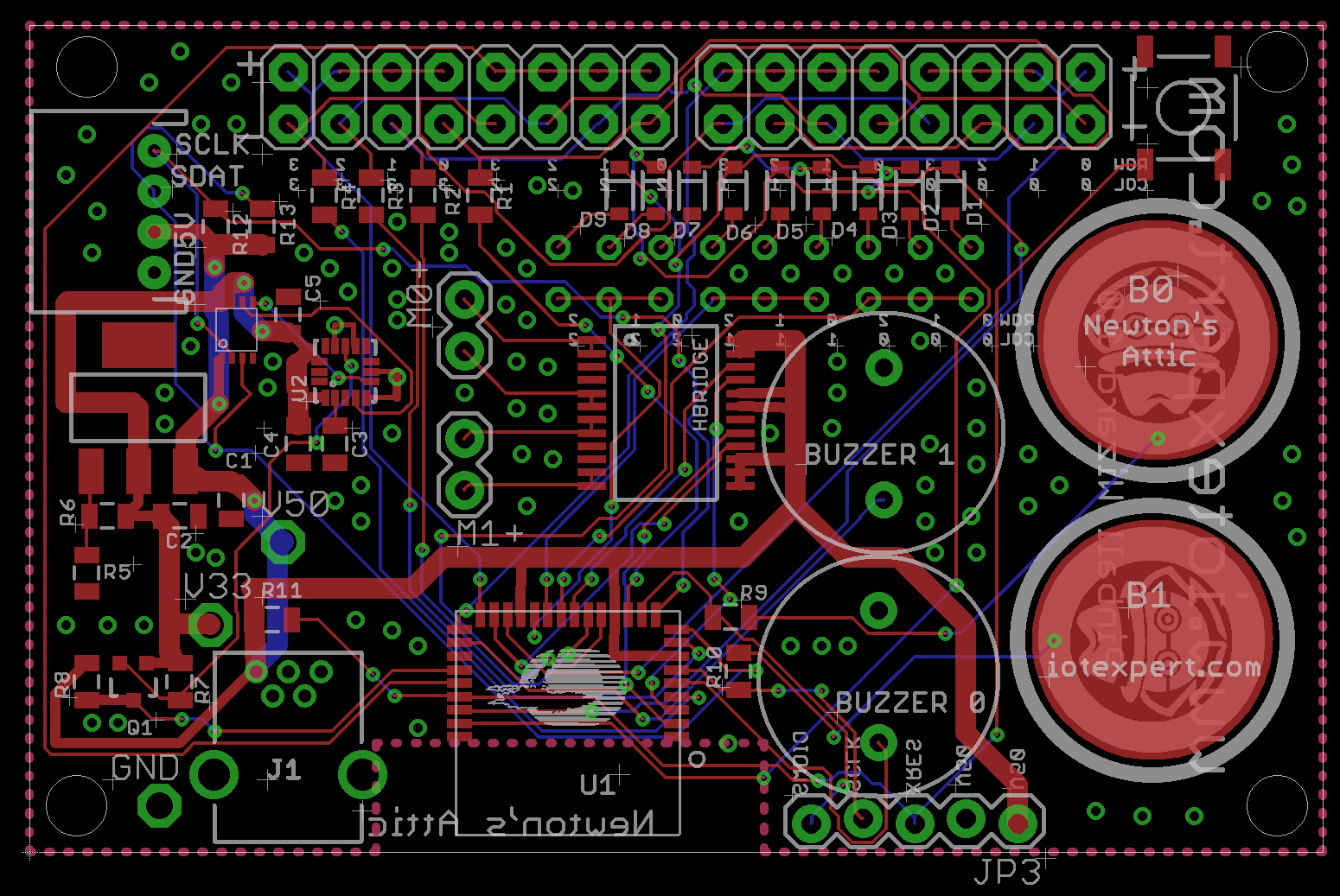
Once I have ripped up all of the nets, I then cross probe all of the nets (In this case M1R which is also pin 31) to make sure that I have the connections in the right place.
OK. Looks good. Not commit the changes and put them back to the github with a change request.
In the next post Ill talk about the new layout.
You can find all of the source code and files at the IOTEXPERT site on github.
Index
Description
Pinball: Newton's Attic Pinball
An introduction to the project and the goals
Pinball: Lotsa Blinking LEDs
Everyone needs a bunch of LEDs on their Pinball Machine
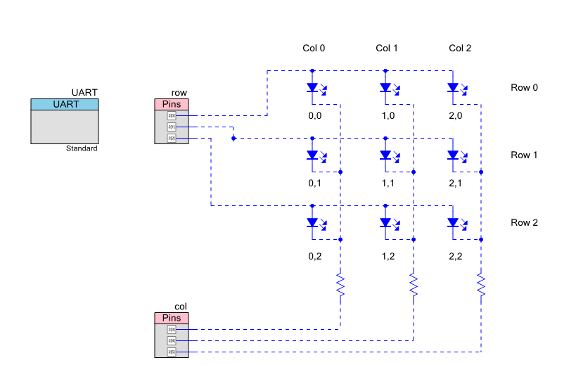
Pinball: Matrix LEDs (Part 1)
Saving PSoC pins by using a matrix scheme
Pinball: Matrix LEDs (Part 2)
Solving some problems with the matrix
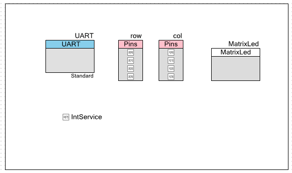
Pinball: Matrix LEDs Component
How to turn the Matrix LED into a component
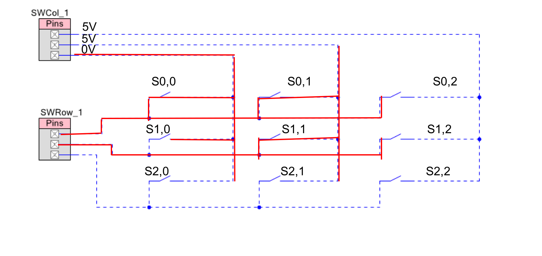
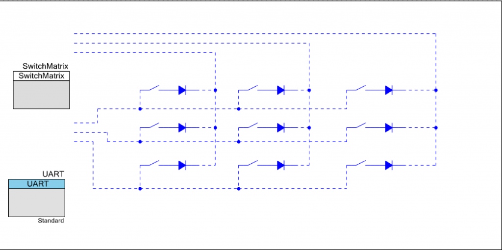
Pinball: A Switch Matrix
Implementing a bunch of switches
Pinball: Switch Matrix Component (Part 1)
The switch matrix component implementation
Pinball: Switch Matrix Component (Part 2)
The firmware for matrix component
Pinball: Switch Matrix Component (Part 3)
Test firmware for the matrix component
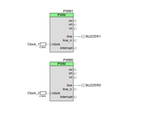
Pinball: The Music Player (Part 1)
The schematic and symbol for a Music Player component
Pinball: The Music Player (Part 2)
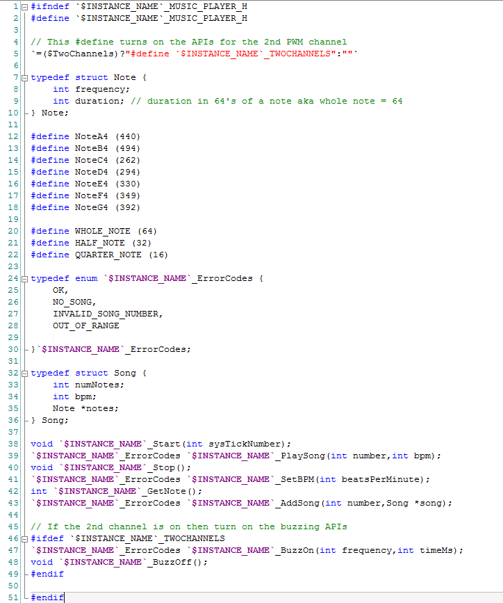
The Public API for the Music Player component
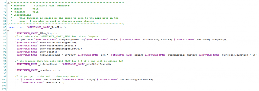
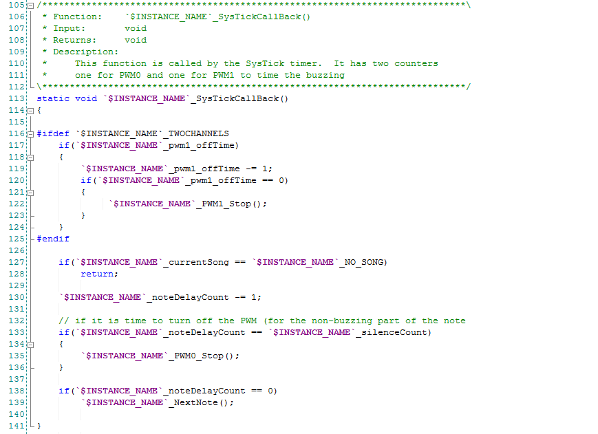
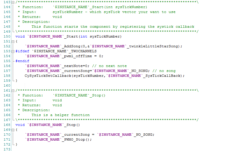
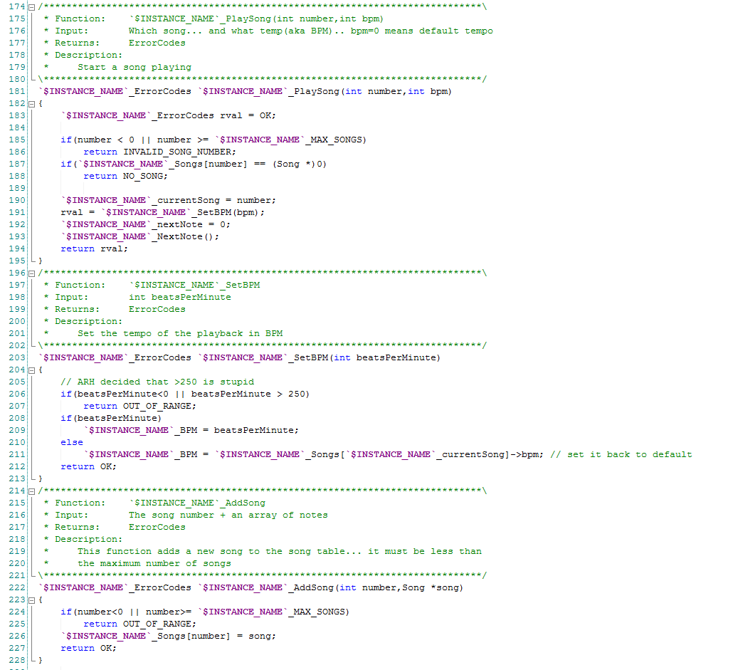
Pinball: The Music Player (Part 3)
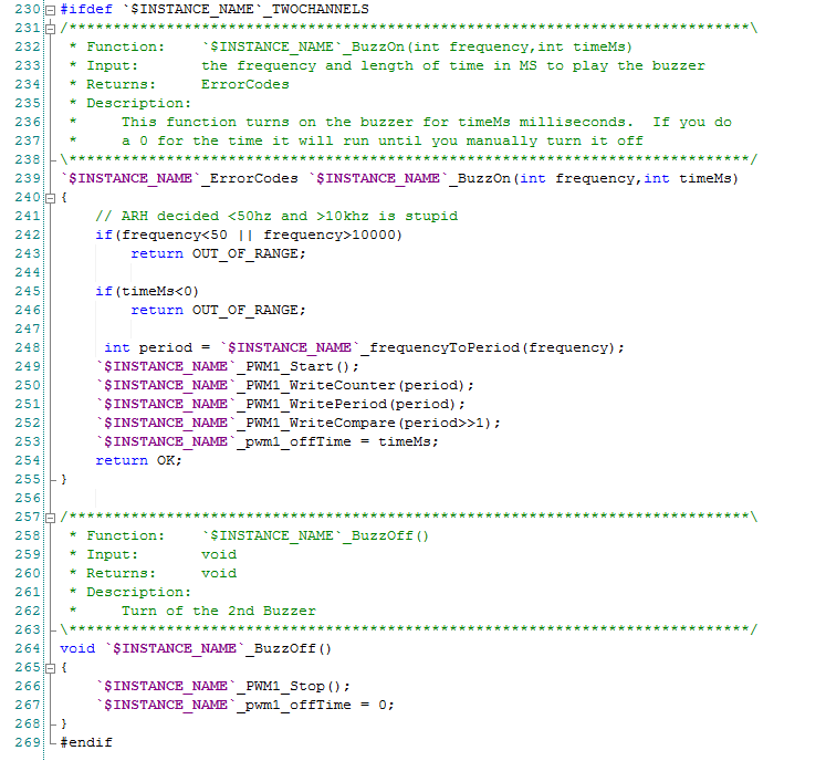
The firmware to make the sweet sweet music
Pinball: The Music Player (Part 4)
The test program for the music player
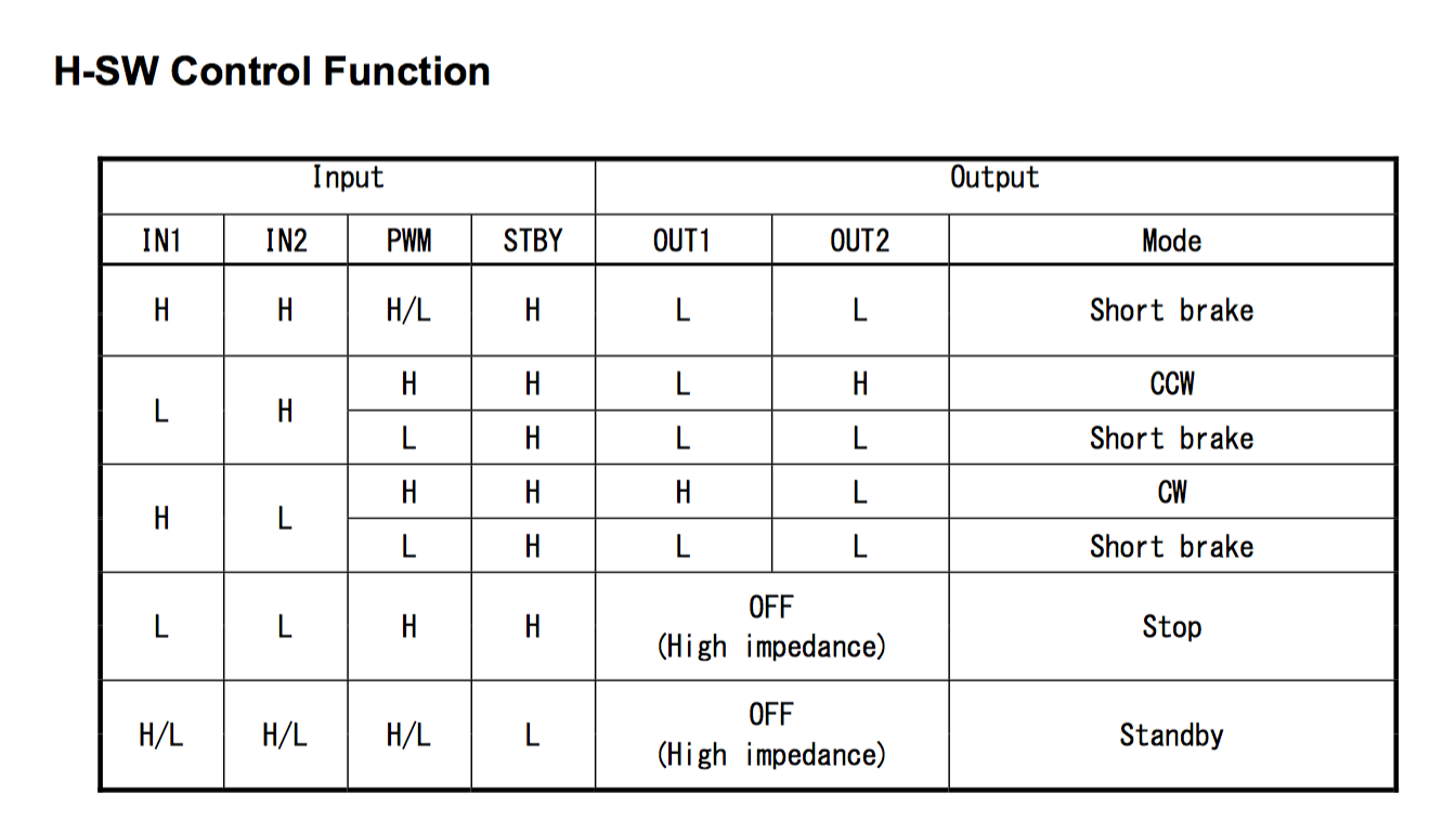
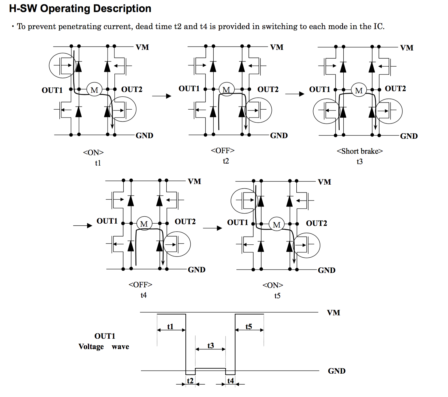
Pinball: The Motors + HBridge
Using an Bridge to control DC Motors
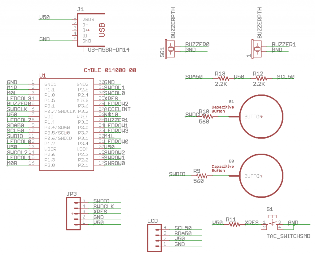
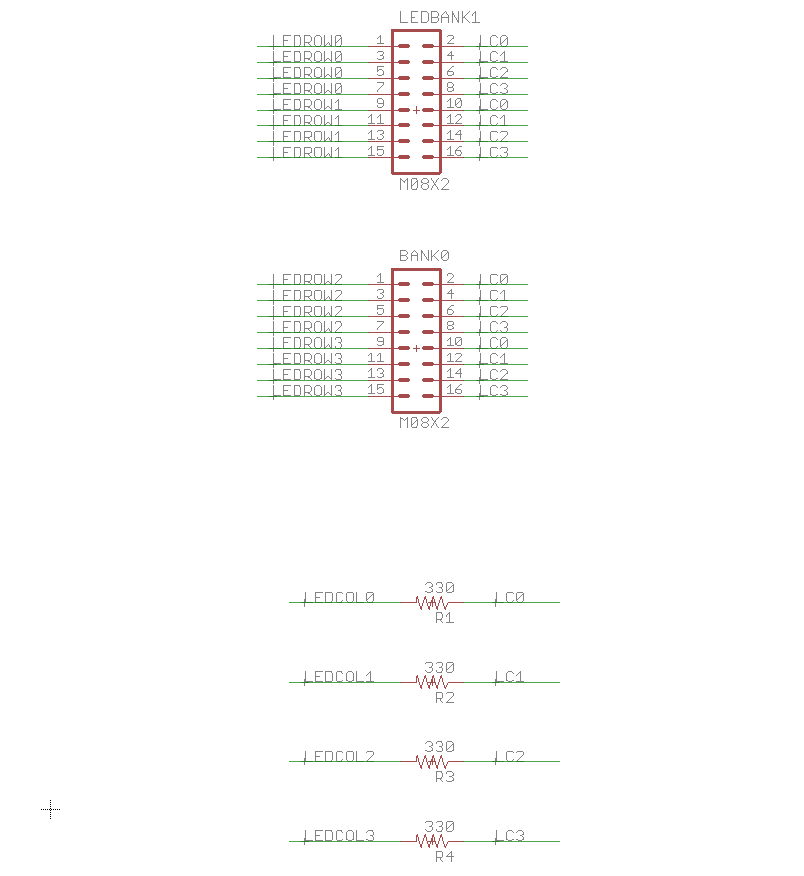
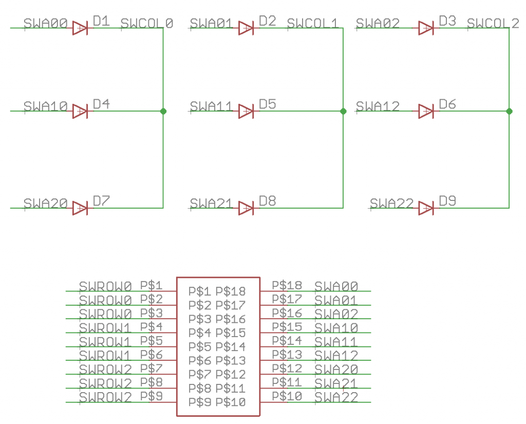
Pinball: The Eagle Schematic
All of the circuits into an Eagle schematic
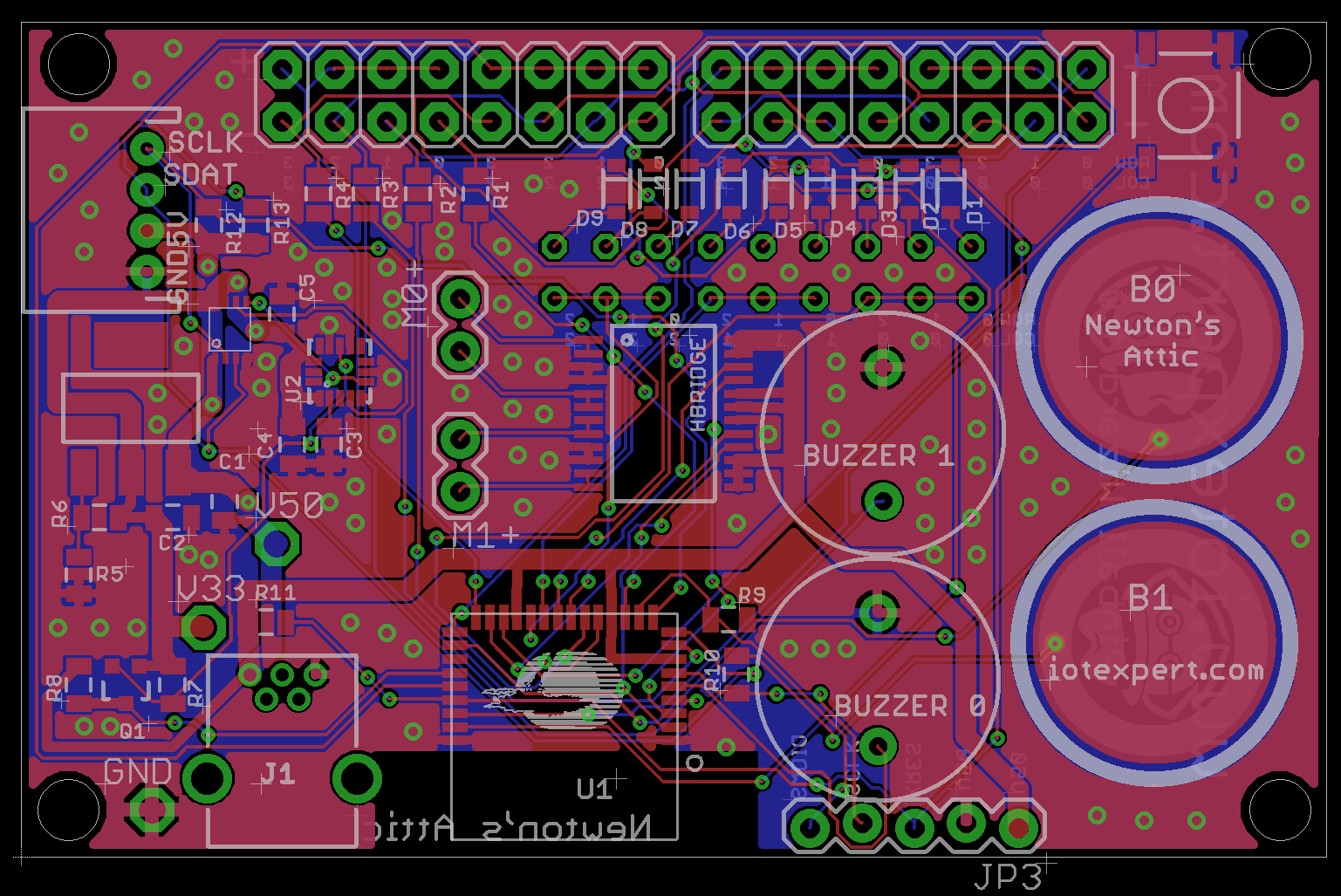
Pinball: The Printed Circuit Board 1.0
The first Eagle PCB layout of the printed circuit board
Pinball: The PCB Version 1.0 Fail
Problems with the first version of the Eagle PCB layout
Pinball: PCB Layout 1.2 Updates using Eagle
Fixing the errors on the first two versions of the Eagle PCB
Pinball: Assemble and Reflow the 1.2 PCB
Assembling the Eagle PCB
Pinball: Testing the Eagle PCB
Firmware to test the newly built Pinball printed circuit board
Pinball: Debugging the Motor Driver
Fixing the motor driver PSoC project
Pinball: Hot-Air Reworking the Accelerometer Solder
Using a Hot-Air Rework tool to reflow a QFN
Pinball: Debugging the LM317 Power Supply- A Tale of Getting Lucky
Debugging the LM317/LM117 power supply


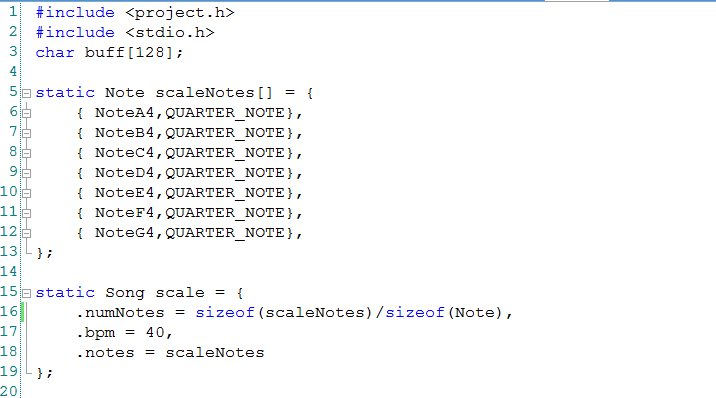
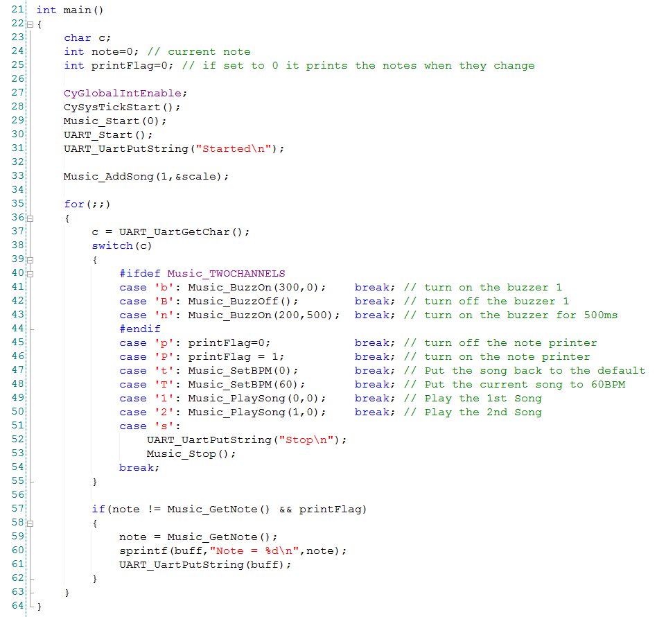
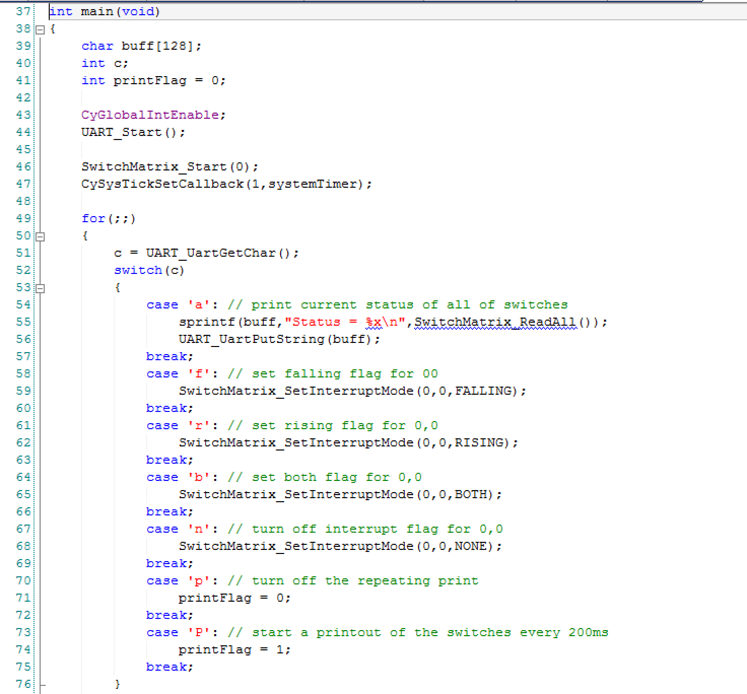
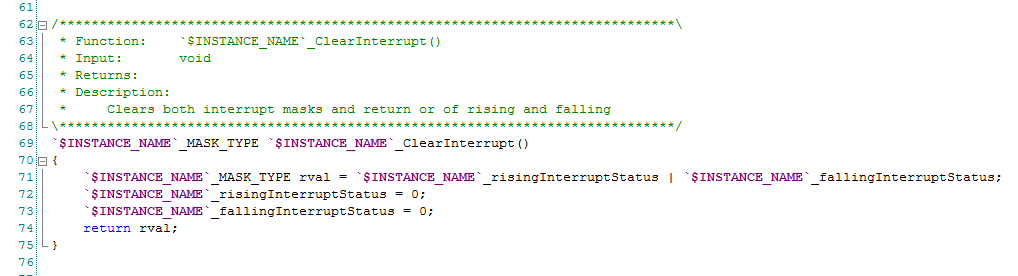
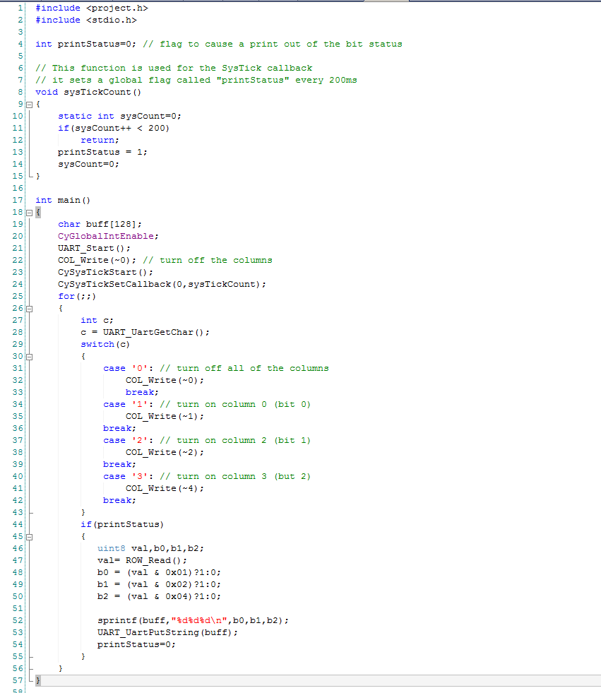
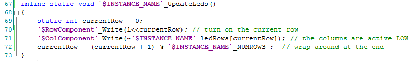
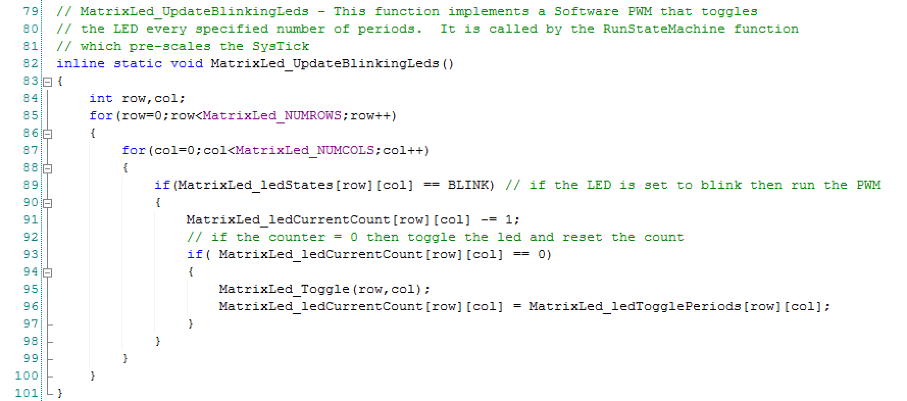
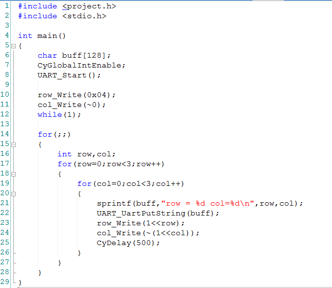
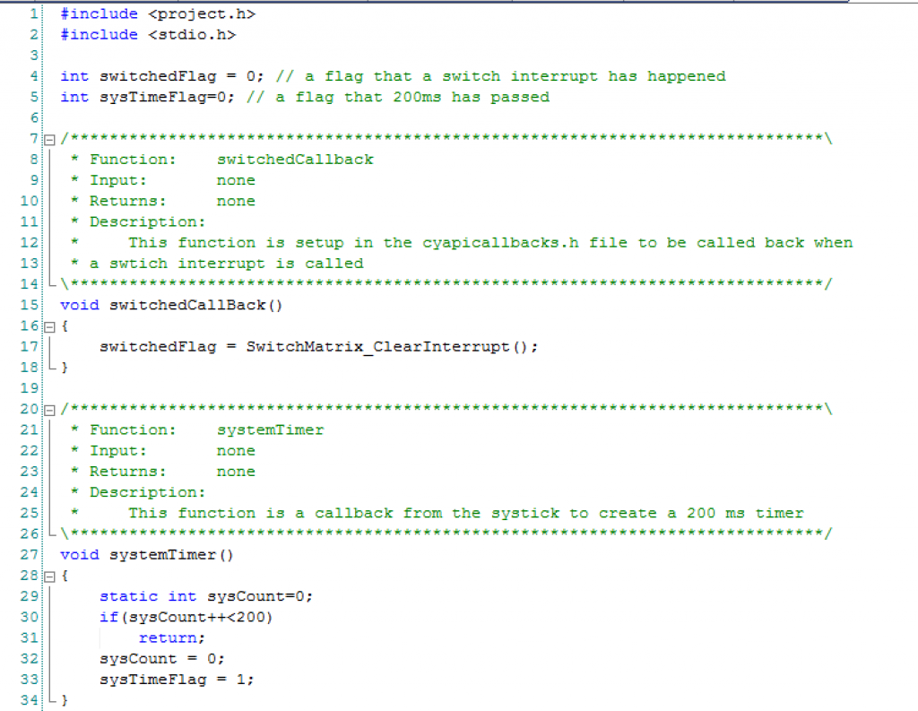 In the main program I first start all of the components, interrupts etc in lines 43-47. On lines 52-75 I process the user input and try out different functions of the component.