CY8CKIT-021: The BLEIOT Component

The PRoC (on the shield) and the baseboard share two pairs of lines that are connected to the Serial Communication Blocks (SCBs) on the chips.  One of the pairs is also connected to the standard I2C Arduino bridge pins and in fact this is how you bootloaded the PRoC in the previous example.  When I started thinking about the problem of making the PRoC on the shield talk to the baseboard I knew that I wanted either side to be able to initiate communication and I did not want either side to poll.  This fact eliminated the master/slave scheme of I2C or SPI.  OK.  UART it is.

The next thing that I knew that I wanted was one set of firmware that would work exactly the same on both side.  This lead me to build a component called BLEIOT.  This component has the following features

  1. It transmits its local status every 20 ms
  2. It is triggered by the Systick
  3. It uses UART to transmit and receive
  4. It has a “Update” API which will update the local and remote state
  5. It has dirtyFlags which are a bit mask of what was written from the other side and is different than the current local status
  6. The component works the same on both sides
  7. It has a data structure that represents all of the peripherals on the shield (LEDs, Thermistor, CapSense Buttons etc)

The system works by having a “local” copy of the state and a last known “remote” copy of the state.  There is a C-Structure that represents each of the system variables (LED, CapSense, …).  The way it works is:

  1. When something changes in your system you use the “Update” API.
  2. The update API changes the local state and the “Write Flags” which is just a bit mask of all of the local variables
  3. Every 20ms the component sends the local table to the remote side (assuming something has been written)
  4. The remote side then looks at each variable that has been “written” and compares it against the local copy.  If they are different then it marks the “dirtyFlags” with the corresponding bitmask
  5. On either side you can monitor the “dirtyFlags”.  If the dirtyFlag for a variable is set then you know that the other  side changed it and you can do something.
  6. When you run the “Update” API if you write your local copy to be the same as the remote copy then you will clear the dirtyFlag.

This project is available as BLEInterface in the CY8CKIT-021 workspace that is in the firmware directory on github at github.com/iotexpert/CY8CKIT-021

Here is a picture of the architecture:

bleiot1

An example:

  1. Everything starts in sync
  2. The PSoC turns on an LED with Pin_Write()
  3. The PSoC calls the BLEIOT_updateLed API
  4. That BLEIOT_updateLed API updates the local state table
  5. That BLEIOT_updateLed API marks the “writeFlag” corresponding to the LED
  6. The PSoC systick triggers the BLEIOT component to send the local table to the PRoC via UART
  7. The PRoC UART receives the table and calls the BLEIOT_receive API
  8. The PRoC BLEIOT component looks at the “Write Flags” and notices that the LED was written, so it marks the dirtyFlag corresponding to the LED
  9. The PRoC  main loop notices the dirtyFlag and turns on the LED using Pin_Write
  10. The PRoC then runs the BLEIOT_updateLed function which updates the local state and clears the dirtyFlag
  11. The PRoC systick calls the BLEIOT_send which sends the local state table to the PSoC
  12. The PSoC calls the BLEIOT_receive
  13. The PSoC BLEIOT_receive notices that the LED was written but that its remote state now matches its local state so it doesn’t do anything

Building the Component

In order to make a component this component I need

  1. A symbol for the component
  2. A schematic (with the UART)
  3. The BLEIOT.h (which is the public interface to the component)
  4. The BLEIOT.c (which hold the functions that makeup the component)

To make the component I start by adding a “library project” to my workspace called BleInterface.  You do this from the new project dialog.

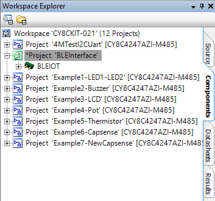
Then I click on the components tab of the BleInterface project.  This is a bit of a trick as it seems like the library is “empty” but it isn’t.

Screen Shot 2016-05-27 at 1.49.08 PM

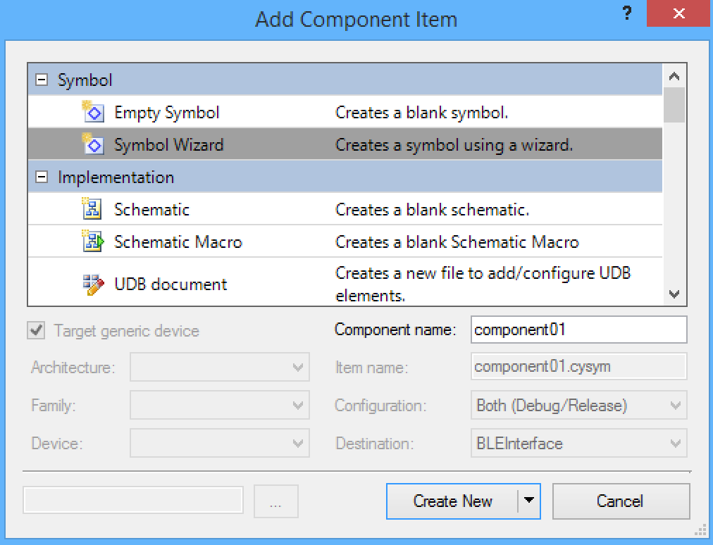
The next step is to create a symbol by right clicking the library and saying “add component item” and choosing Symbol Wizard.  If you are doing this make sure that you give the component a good name (or at least something better than “component01”

Screen Shot 2016-05-27 at 1.54.36 PM

This component does not have any visible terminals so just accept the defaults.

In the next step I create a schematic to hold the UART component.  When you add the component item for the schematic you need to configure the architecture to target the PSoC4 family in order to have access to place the SCB UART.  After you have placed the UART component you will automatically get “buried” pins which you can assign for that component.

Now that I have a schematic and a symbol, the last steps are to add the .h and .c

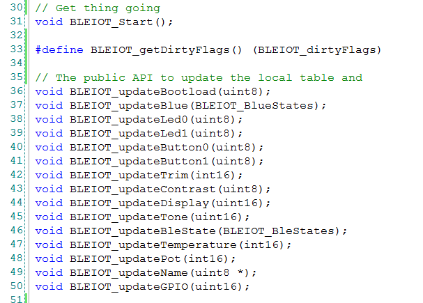
The .h contains the public interface to the component.

Screen Shot 2016-05-27 at 2.46.10 PM

This section defines the public interface.  On update function per system state.

Screen Shot 2016-05-27 at 3.36.00 PM

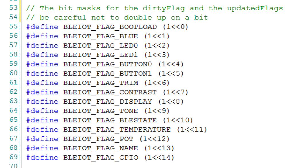
The bit masks for the dirtyFlags and updatedFlags

Screen Shot 2016-05-27 at 2.46.48 PM

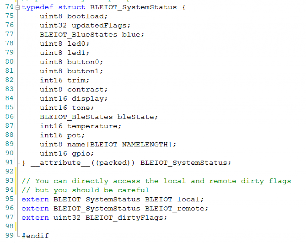
The definition of the table of variables.

Screen Shot 2016-05-27 at 2.47.15 PM

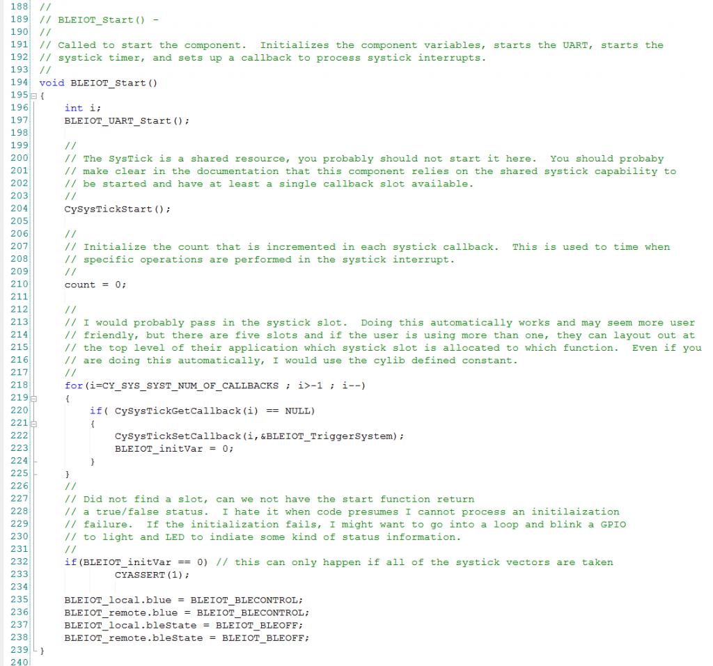
The last thing that you need is “BLEIOT.c”

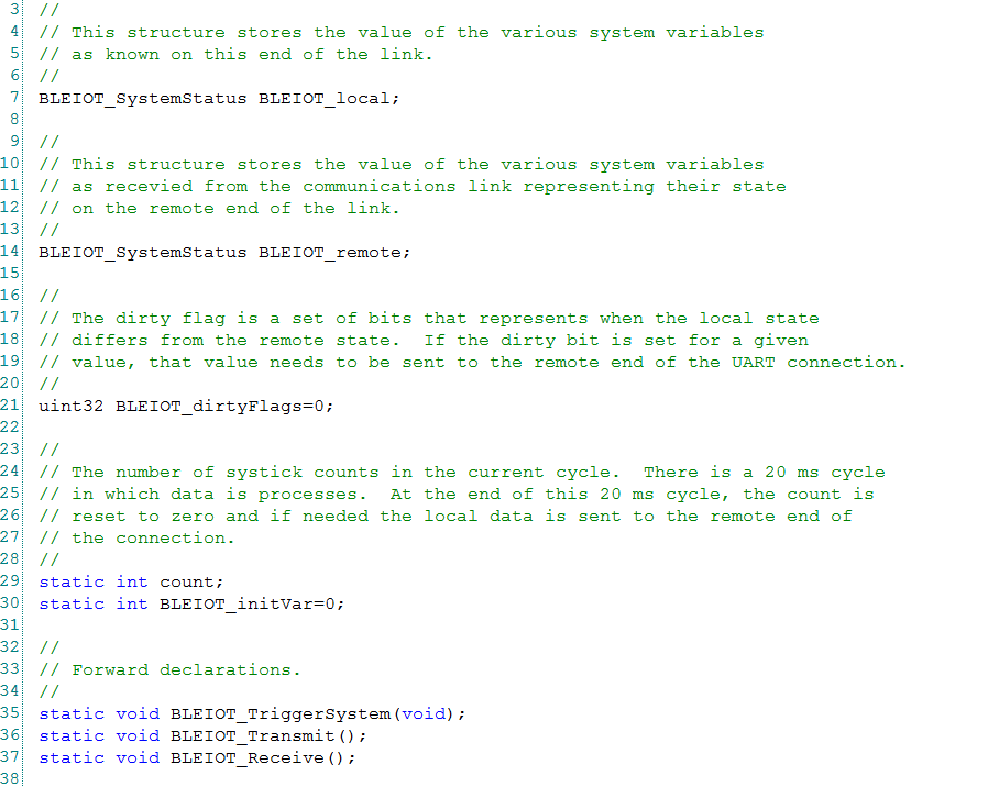
Screen Shot 2016-05-28 at 8.31.24 AM

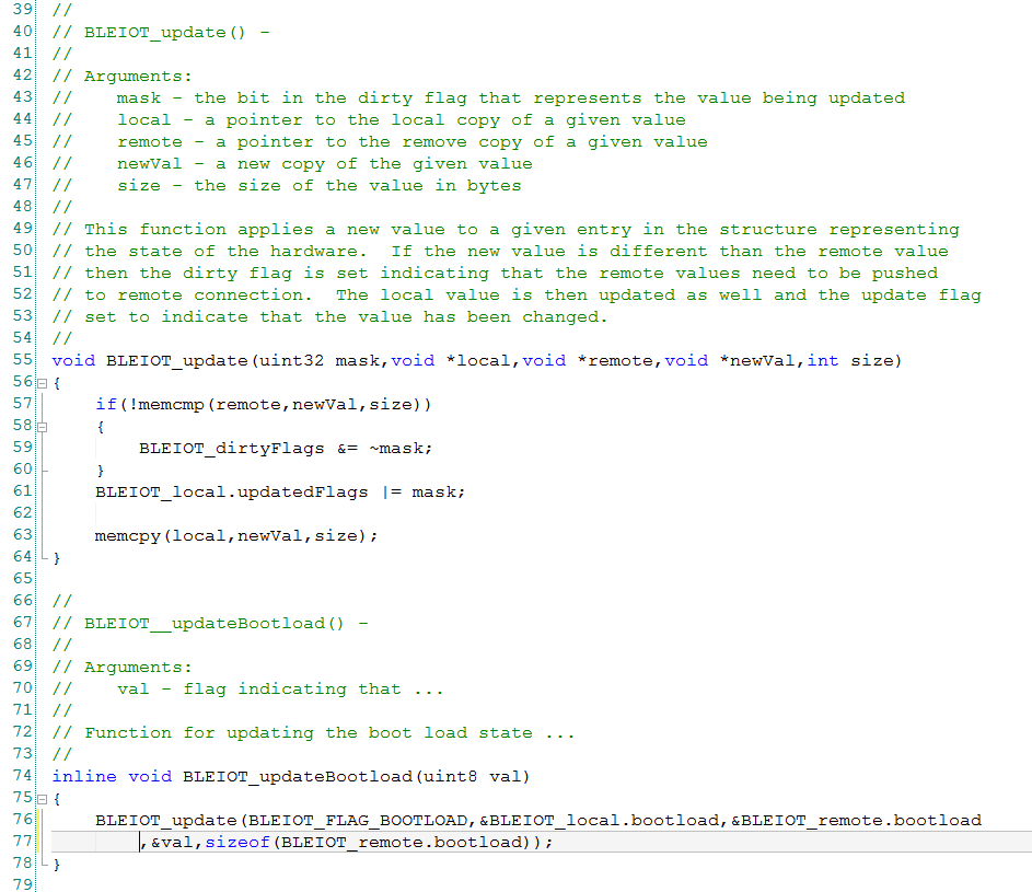
The update function is a generic function that will “update” the local table with the current value of one of the local status (LED0, CapSense …).  This function is called by the various helper function (updateLed0, updateBootload, updateCapsense,…)

Screen Shot 2016-05-28 at 8.32.08 AM

Screen Shot 2016-05-28 at 8.37.10 AM

Screen Shot 2016-05-28 at 8.37.35 AM

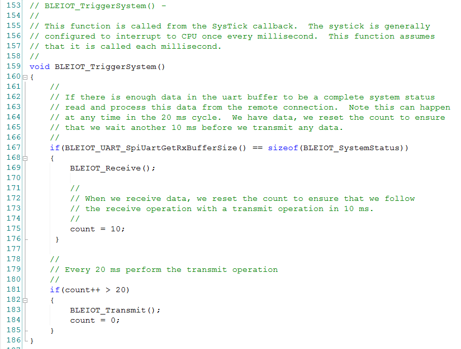
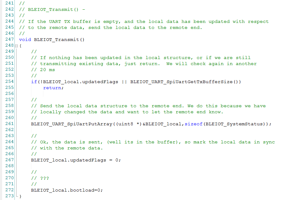
This function sends the data to the other side when it gets a turn from the systick interrupt

Screen Shot 2016-05-28 at 8.37.50 AM

In the next post Ill show you an example project of the BLEIOT.

index description
CY8CKIT-021: A Simple FM/PSoC + BLE Demonstration Board Introduction to CY8CKIT021
CY8CKIT-021: The first four example projects Use the LEDs Buzzer 7-Segment display and the Potentiometer
CY8CKIT-021: The next three example projects Use theThermistor and two Capsense Examples
CY8CKIT-021: Bootloading the PRoC How to put firmware into the PRoC
CY8CKIT-021: The BLEIOT Component A custom component to communicate with the PRoC/PSoC
CY8CKIT-021: Using the BLEIOT Component A full example of the tho MCUs talking
CY8CKIT-021: The PRoC BLE Firmware How to make PRoC Firmware and use it with the BLEIOT Component
CY8CKIT-021: Example 10 - the new IOS App How to build and IOS App to talk to the development kit

CY8CKIT-021: Bootloading the PRoC

Now that I have shown you how to make all of the basic functions of the devkit work, I really want to make this shield into an IOT Device.  In order to do this I need to:

  1. Get the bootloading to work (so I can put firmware into the PRoC)
  2. Have a scheme to communicate between between the PRoC and the Baseboard (the subject of the next posts)
  3. Have BLE Firmware (the subject of the next posts)

Bootloading the PRoC

When the India team sent me the shield, the EZ-USB PRoC came preprogrammed with a bootloader project.  They also sent me the bootloader project that is programmed into the device.  That project, called “I2C_Bootloader”, is in the workspace that you can find in the firmware directory at github.com/iotexpert/CY8CKIT-021.  In order to make your own firmware application for that PRoC you need to make a reference to the bootloader project in the bootloadable component.

When I first plugged in the board I thought that I was going to have a seizure as the blue LED is blinking like crazy.  That has got to go!  To get firmware into the PRoC you either need to solder a header onto the board so that you can use a miniprog-3 (which I also did) and/or you can bootload the firmware.  The I2C Pins on the PRoC are connected to the KitProg I2C pins on the baseboard.

Bootloading is the process of transferring a hex file image via a serial connection (I2C in this case) into the chip, then flashing it into the memory in the right place.  I wrote in detail about this process in this post “The Creek: PSoC4 Bootloader + Firmware”.    Here is a picture of the architecture:

bootloading

First ill explain the bootloader project.  This project will:

  • Wait for 100ms, and if the Pin_BL_Select is held low it will start the bootloader otherwise it will start application.  This was done so that you could signal the PRoC from the board that it was plugged into to start the boot loading process via a GPIO.
  • If there is no application firmware or the application firmware is invalid then it will start the bootloader
  • The bootloader will listen to the I2C on address 0x0B and load in firmware when it gets a request
  • The application is yours to write.

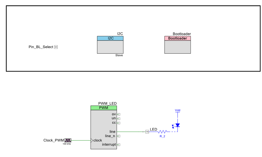
The schematic is simply a blank SCB I2C component to service the Bootloader, a GPIO pin, a blinking LED using the PWM and the Bootloader component.

Screen Shot 2016-05-26 at 7.31.10 AM

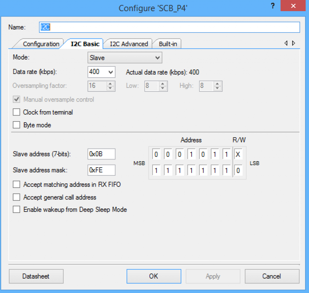
Here is the configuration of the I2C component — just 400KBS and slave address 0x0B:

Screen Shot 2016-05-26 at 9.40.45 AM

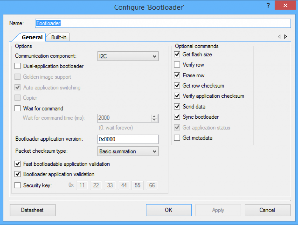
Here is the configuration of the Bootloader:

Screen Shot 2016-05-26 at 9.40.27 AM

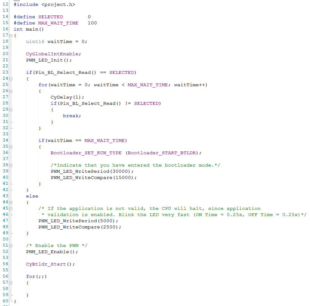
And finally the main.c

Line 23-49 are run if the digital input pin is held low when the chip is booted… indicating that you want the bootloader to start.  You use this to get the PRoC back into the bootloader mode if you have already programmed firmware into it that does something else.

Line 25-32 is a loop that goes for 100ms and makes sure that the line is held down the whole time.  If it is NOT held down then it break out of the loop and start the application (By falling out of the loop)

Line 34-42: if the pin was held down the whole time, then configure the the bootloader component to start

Line 54:  Start the bootloader component.  The component is configured to start the application immediately upon startup.  If line 36 is run, then it will start the boot loading process.  (this was a bit confusing to me when I first looked at this program)

Screen Shot 2016-05-26 at 7.35.47 AM

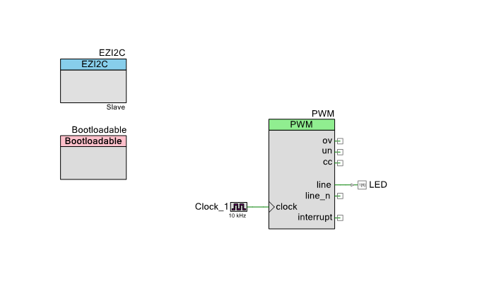
A Bootloadable Application

Now that you understand the bootloader application, Ill build a simple simple bootloadable (just a program that can be loaded by the bootloader).  My application will do only two things.

  1. It will blink the LED at 1HZ
  2. If will have an EzI2C component.  If there is something other than “0” written to address 0 it will launch the bootloader (so you can restart the bootloader)

Screen Shot 2016-05-27 at 5.29.44 AM

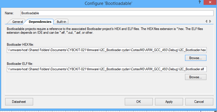
Once the schematic is configured you need to configure the bootloadable component.  Basically you need to tell it where the bootloader hex file exists on your system.  This is required because the bootloader and the bootloadable need to come in pairs.

Screen Shot 2016-05-27 at 4.52.53 AM

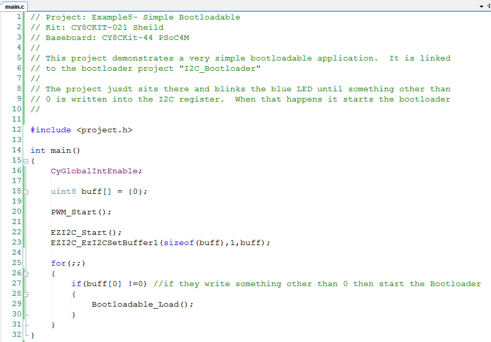
The main.c is very straightforward.

Screen Shot 2016-05-27 at 5.27.11 AM

Once you have the project put together you will use the “build” menu to create the “.cyacd” file.  That is just the hex file in a format that can be read by the Bootloader host.  The Bootloader host know how to talk to a Cypress I2C bridge (either KitProg or MiniProg-3) and then send the CYACD file to the PRoC bootloader.

The process is

  1. Start the Bootloader host (from the windows start menu or by right clicking the bootloadable component)
  2. Find the .CYADC file for your project
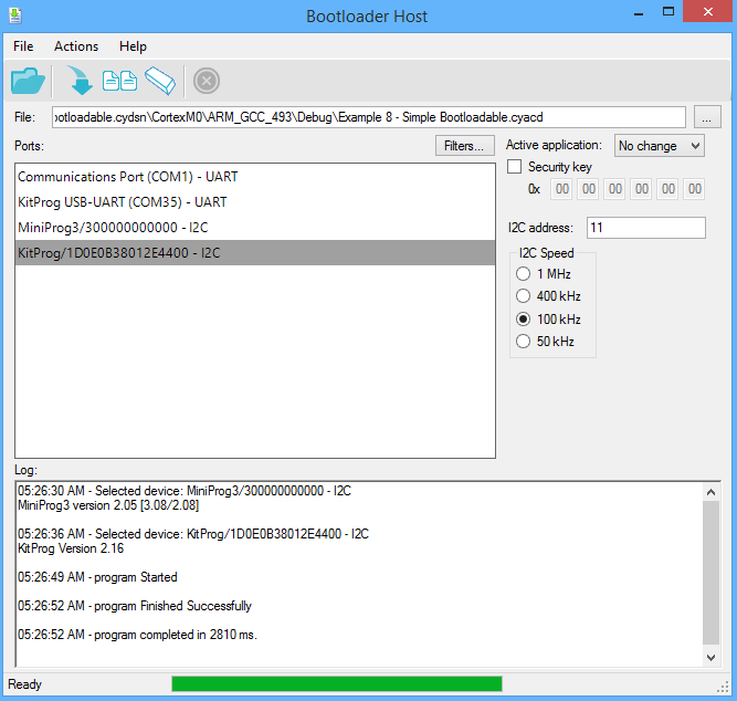
  3. Select the KitProg and the correct I2C address (remember I set 0x0B which is also known as 11)
  4. Then click the “download” arrow

After each of those steps is done you will see the file being downloaded.  Then you will see you the Blue LED on the kit start blinking a 1hz.  Success!

Screen Shot 2016-05-27 at 5.26.58 AM

If you are ready to start the bootloader again you now have two options

  1. Hold down the PRoC Pin P04 for 100ms as the PRoC boots
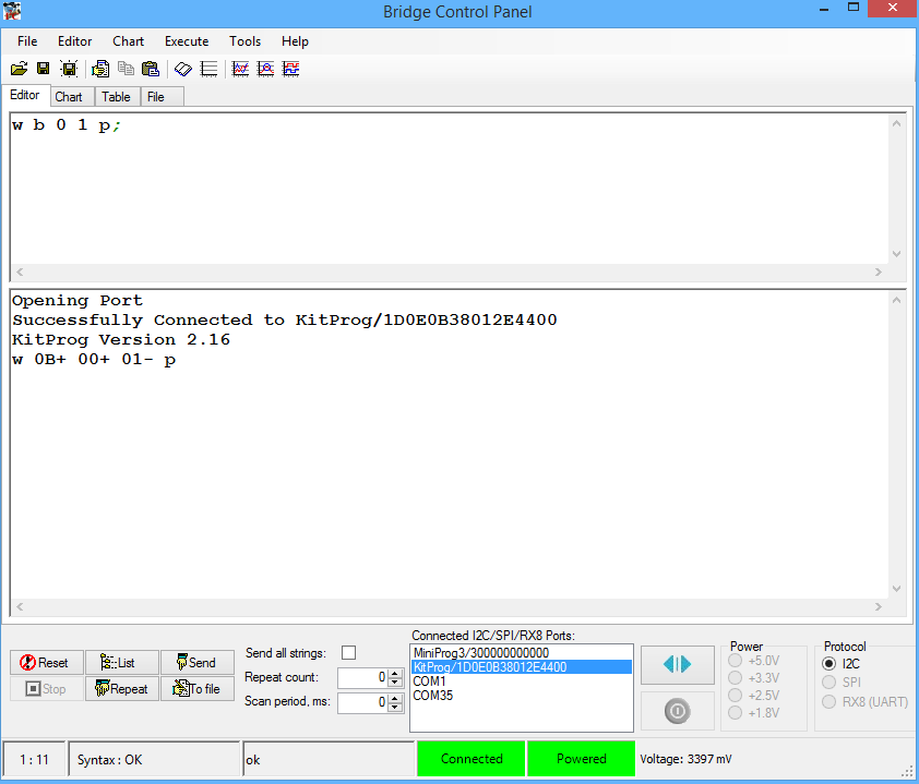
  2. Attach the I2C bus and write a 1 to I2C address 0x0B.  The easiest way to do this is with the bridge control panel (see the picture below)

Screen Shot 2016-05-27 at 5.28.02 AM

Finally, On Cypress.com we have a ton of good Application Notes and data sheets to help you understand Bootloading.

AN73854 – PSoC® 3, PSoC 4, and PSoC 5LP Introduction to Bootloaders

The Booloader and Bootloadable Component Datasheet

AN86526 – PSoC® 4 I2C Bootloader

AN73503 – PSoC® USB HID Bootloader

AN60317 – PSoC® 3 and PSoC 5LP I2C Bootloader

AN68272 – PSoC® 3, PSoC 4, and PSoC 5LP UART Bootloader

Now that you know how the bootloader and bootloadable projects work Ill address the communication between the PSoC and the PRoC in the next post.

CY8CKIT-021: The Next 3 Example Projects

In the previous post I introduced 4 basic example projects.  In this post Ill finish up the examples with the Thermistor and two Capsense projects.

  • Example 5: A Thermistor
  • Example 6: 2 Capsense Buttons (using the V2.x component)
  • Example 7: 2 Capsense Buttons (using the new V3.x component + tuner)

Example 5: The Thermistor

A thermistor is a resistor that changes resistance with temperature in a known way.  You can use it in combination with a precision reference resistor to calculate temperature.  PSoC Creator provides a component for making this easy as the actual formula is crazy.  Here is the schematic.  R1 is the known reference resistor.  RT1 is the thermistor.  J6 is a selector that lets you select the analog input from the shield to either be the POT or the Thermistor.

Screen Shot 2016-05-25 at 7.07.26 AM

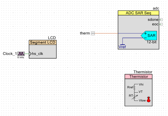
The schematic is simple.  Just an Analog to Digital Convertor and the LCD from the previous design plus the Thermistor.  Notice that the Thermistor symbol shows the configuration that you need on the schematic to make this work.

Screen Shot 2016-05-25 at 7.10.17 AM

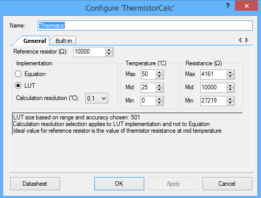
In the Thermistor configuration window you get to select the size of the reference resistor (in this case it is 10K) and if you want to use a LUT or use an Equation.  If you choose LUT then PSoC Creator will pre-calculate a temperature versus resistance table and embed that into your program.  This will enable very fast calculation of temperature but will take more flash.

Screen Shot 2016-05-25 at 7.11.48 AM

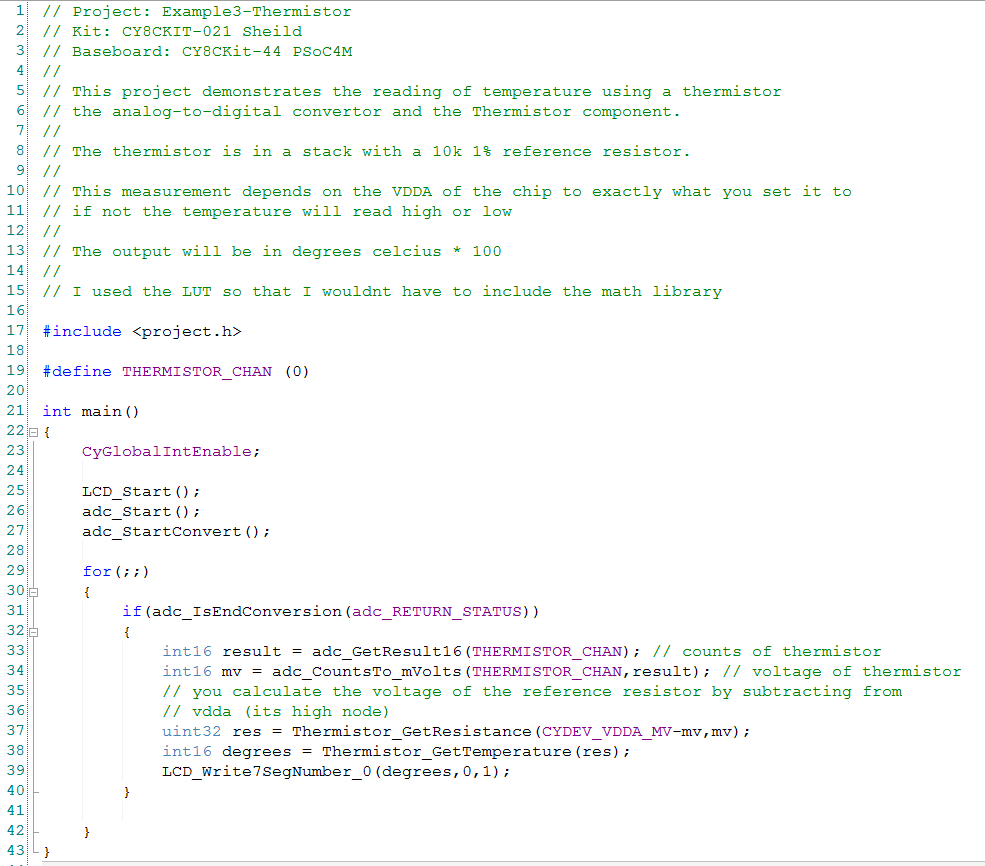
The main.c just reads the voltage, calculates the resistance (using the API), calculates the temperature (using the API) and then displays it on the LCD.  The only problem with this whole setup is that it depends on knowing the exact VDDA voltage because you need to know the voltage across the reference resistor.  I use the handy PSoC Creator #define CYDEV_VDDA_MV to find out what the configured voltage.  The problem with this circuit is that the VDDA will vary and this will throw off the temperature calculation.  This could have been solved if we had used two differential measurements, but we were out of pins.

Screen Shot 2016-05-25 at 7.15.20 AM

Example 6: The CapSense Buttons using the 2.x Component

There are two CapSense buttons on this Development Kit.  I started with the old CapSense component because I know the APIs without looking at the examples.  We have now upgraded the component to support features in the new CapSense block (which I will show in the next example).  The V2.x schematic is simple with just the CapSense component plus the two LED pins.

Screen Shot 2016-05-25 at 7.23.14 AM

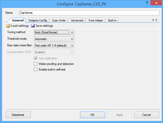
The CapSense component uses the default settings including SmartSense tuning.

Screen Shot 2016-05-25 at 7.23.40 AM

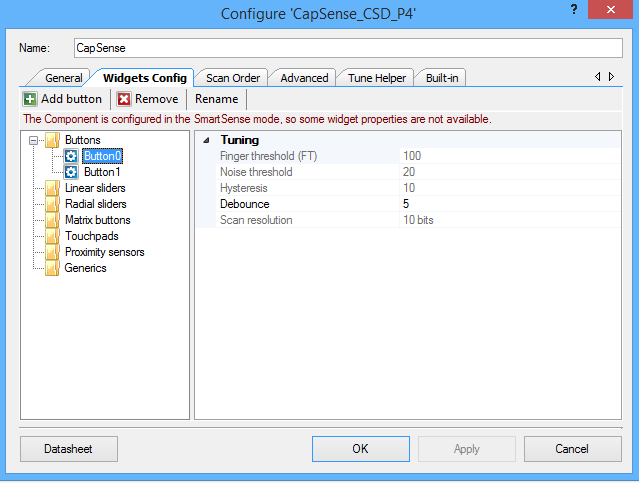
I add two buttons and use the default values.

Screen Shot 2016-05-25 at 7.23.51 AM

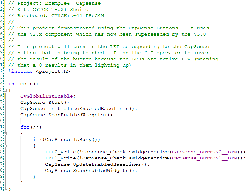
The code is also very simple.

Screen Shot 2016-05-25 at 7.27.01 AM

Example 7:  CapSense 3.0

In PSoC Creator 3.3 we released a new component to support features in the new CapSense block that was put into the new PSoC 4000S/4100S family.  Like the previous example, this project will light up the LEDs when the corresponding button is pressed. The addition in this example is the EZi2C to support the tuner (which is also new).

Screen Shot 2016-05-25 at 7.42.07 AM

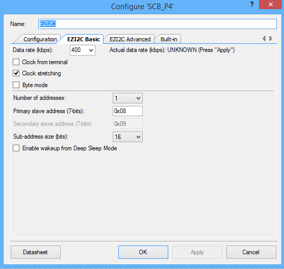
In the EZI2C you need to change the defaults from 100kbps to 400 kbs and 8-bit subaddress to 16-bit subaddress.

Screen Shot 2016-05-25 at 7.42.20 AM


The first time I put this design together I noticed that the CapSense buttons were very sensitive.  Very means that you get a touch when your finger is 1mm or more from the surface of the button.  I thought that as long as I was going to manually tune some of the buttons that I will show the new tuner-which is really cool-in this example.

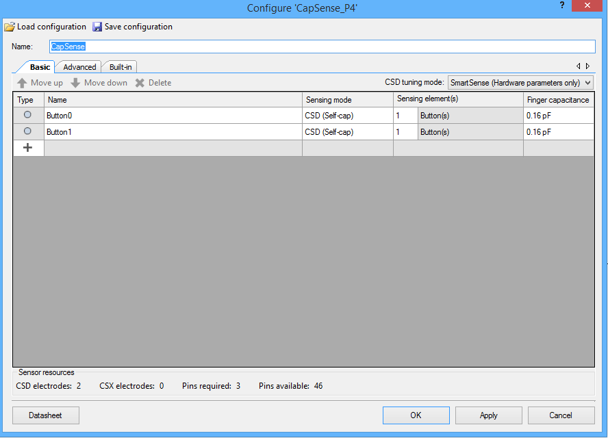
First configure two buttons and set the tuning to SmartSense (Hardware parameters only).

Screen Shot 2016-05-25 at 7.42.39 AM

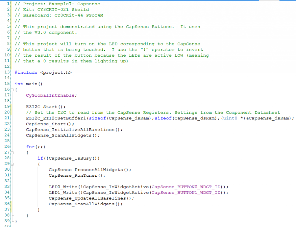
The main.c is also very simple.

Screen Shot 2016-05-25 at 7.45.36 AM

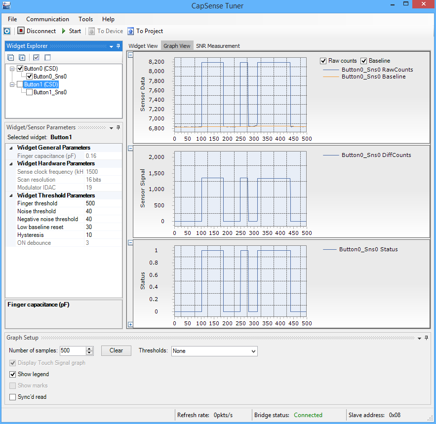
The last step is to run the tuner.  The default finger threshold is 100.  To make the button less sensitive I increase the button touch to 500.  You can see in the picture below that Button 0 has about 1300 counts of signal when I am touching the button so 500 gives us plenty of room to not miss a touch.  You can see that just sitting there untouched that the signal is about 6850 counts and when there is a touch it is about 8150.

Screen Shot 2016-05-25 at 10.49.30 AM

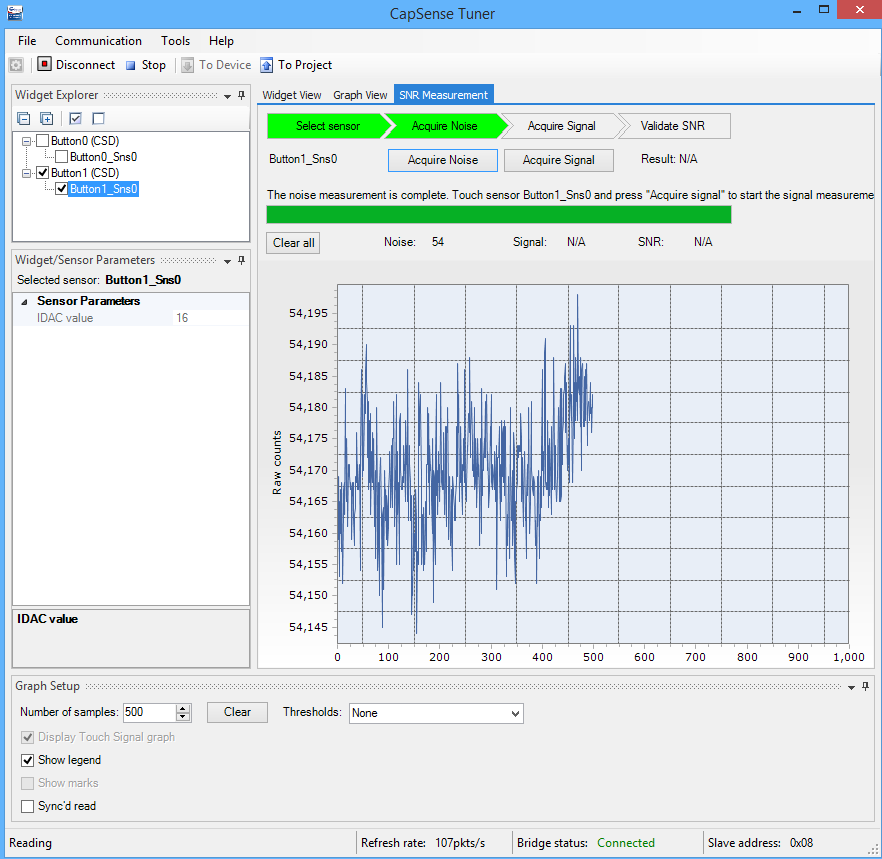
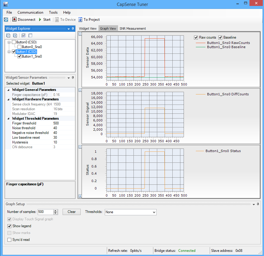
Button 1 is more interesting.  I decided to run a signal-to-noise measurement on the button.  Here is the “acquire noise” graph.  You can see that just sitting there untouched, the signal is about 54170 and there is about 54 counts of noise.  That is quite a bit different than Button 0 which has a baseline of about 6850.  I don’t know why they are so different.

Screen Shot 2016-05-25 at 10.51.29 AM

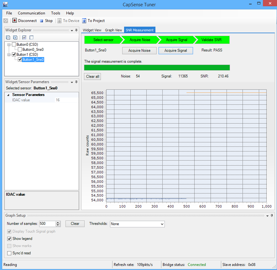
When I run the signal acquisition I get this graph.  You can see that a “touch” is about 65500 which means that there is about 10000 counts of difference, so a threshold of 500 will also be stable, in fact it could be 5000 and work just fine.

Screen Shot 2016-05-25 at 10.52.12 AM

Here is the touch graph:

Screen Shot 2016-05-25 at 10.50.37 AM

In the next post I will talk about the BlueTooth Firmware.

Alan

index description
CY8CKIT-021: A Simple FM/PSoC + BLE Demonstration Board Introduction to CY8CKIT021
CY8CKIT-021: The first four example projects Use the LEDs Buzzer 7-Segment display and the Potentiometer
CY8CKIT-021: The next three example projects Use theThermistor and two Capsense Examples
CY8CKIT-021: Bootloading the PRoC How to put firmware into the PRoC
CY8CKIT-021: The BLEIOT Component A custom component to communicate with the PRoC/PSoC
CY8CKIT-021: Using the BLEIOT Component A full example of the tho MCUs talking
CY8CKIT-021: The PRoC BLE Firmware How to make PRoC Firmware and use it with the BLEIOT Component
CY8CKIT-021: Example 10 - the new IOS App How to build and IOS App to talk to the development kit

CY8CKIT-021: The First 4 Example Projects

Recall from the last post that the CY8CKIT-021 has 6 different peripherals to attach to.  The first thing that I did with the board is build a simple example for each of the peripherals.  I built all of the projects on the PSoC4200M development board which is also known as CY8CKIT-044.  The pinout for the other kits will be different, but the PSoC projects will be the same, but with a different pin map.  Later in the week I’ll show projects for the FM0 and FM4 development kits.  All of these projects  are available at github.com/iotexpert/CY8CKIT-021 in the firmware directory and in a single workspace.

  • Example 1: 2 LEDs
  • Example 2: A buzzer
  • Example 3: A direct drive 7-segment LCD
  • Example 4: A potentiometer
  • Example 5: A thermistor
  • Example 6: 2 Capsense Buttons (using the V2.x component)
  • Example 7: 2 Capsense Buttons (using the new V3.x component + tuner)

Example 1: Two LEDs

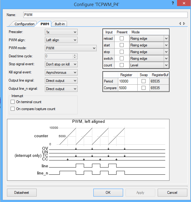
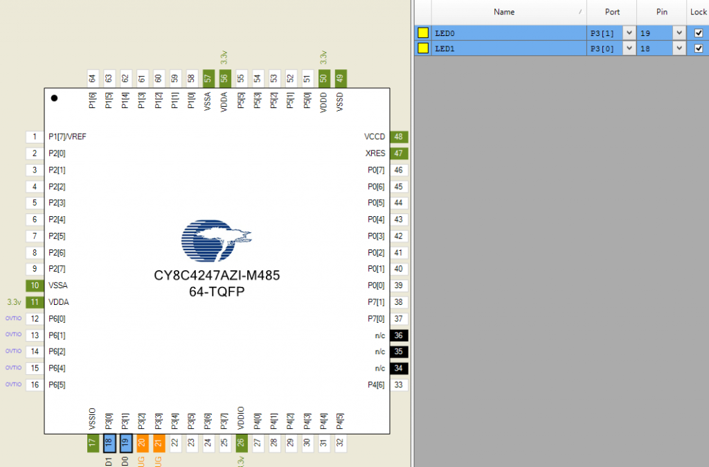
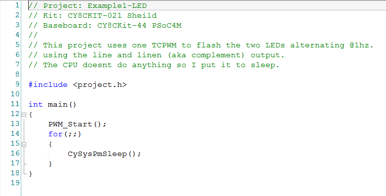
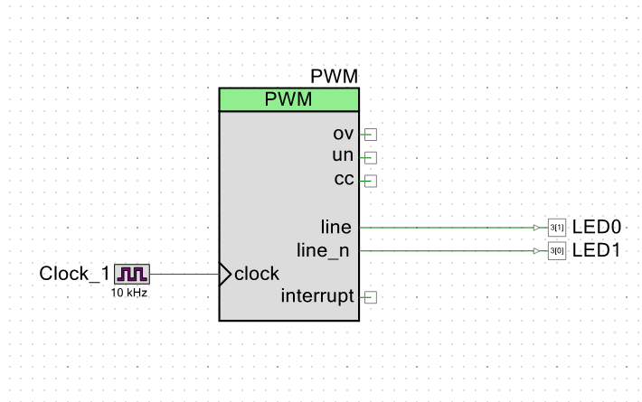
This weekend I taught people at the Bay Area Maker Faire to program PSoC.  I told them that the first project that you always do is the blinking LED.  This simple project is perfect to show that the tools work etc.  So, that is what we will do here.  For this example I used a TCPWM to blink the two LEDs.  One LED is connected to the line output and the other one is connected to the line_n output.  This will cause the LEDs to alternate.  The only other slightly interesting thing that I do is put the CPU to sleep and just let the hardware do the blinking.


Screen Shot 2016-05-24 at 8.21.03 AM

Screen Shot 2016-05-24 at 8.23.44 AM

Screen Shot 2016-05-24 at 8.21.26 AM

Screen Shot 2016-05-24 at 8.21.43 AM

Example 2: A buzzer

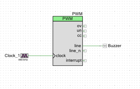
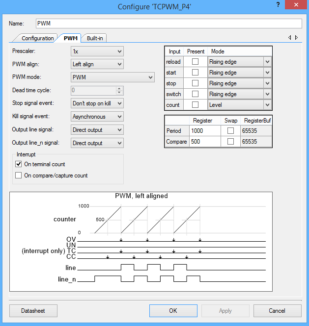
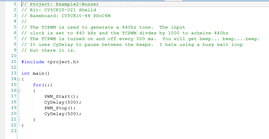
To beep the buzzer I will use a 440hz tone that is generated by the TCPWM which divides an input clock of 440khz by 1000 to achieve the note “A” or “A4”.  To make the tone turn on and off I do my most hated thing, use the CyDelay to make a busy wait loop.  Basically, I turn on the PWM, wait for 500ms then turn it off, wait for 500ms and then go back to the start.

Screen Shot 2016-05-24 at 8.25.20 AM

Screen Shot 2016-05-24 at 8.25.33 AM

Screen Shot 2016-05-24 at 8.26.34 AM

Screen Shot 2016-05-24 at 8.25.53 AM

Example 3: Direct Drive 7 Segment LCD

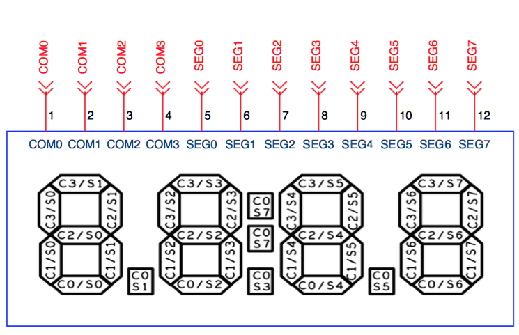
A very cool feature of almost all of the PSoCs is their ability to drive “direct drive LCDs”.  This is a very low cost, low power way to add a display to your design.  This display we used on this board is a Lumex LCD-S401M16KR  that costs $0.73 from Mouser.  Internally, all LCDs are organized into rows and columns a.k.a Segments and Commons.  To enable a particular segment in the LCD you need to select the correct row and column.  Then to make a symbol on the screen you need to select the combination of segments for that number.  For example, from the picture below, to make a “7” on the left digit you would need to turn on C3/S1, C2/S1, and C1/S1.  This would be a serious pain in the ass, but conveniently, the PSoC Creator segment LCD component does this for you automatically.

Our Lumex display is organized into 8 Segments and 4 Commons.  This means that it takes 12 pins on the chip and can show 32 segments.  The segments are organized into 4 characters with 7 segments (28 total segments), a decimal point between each character (3 segments) and a colon. Here is a picture:

Screen Shot 2016-05-24 at 8.53.59 AM

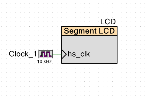
First add the segment LCD component to your design and attach a clock

Screen Shot 2016-05-24 at 9.17.07 AM

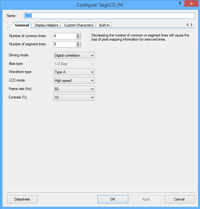
Then make the top level configuration (4 commons and 8 segments)

Screen Shot 2016-05-24 at 9.17.15 AM

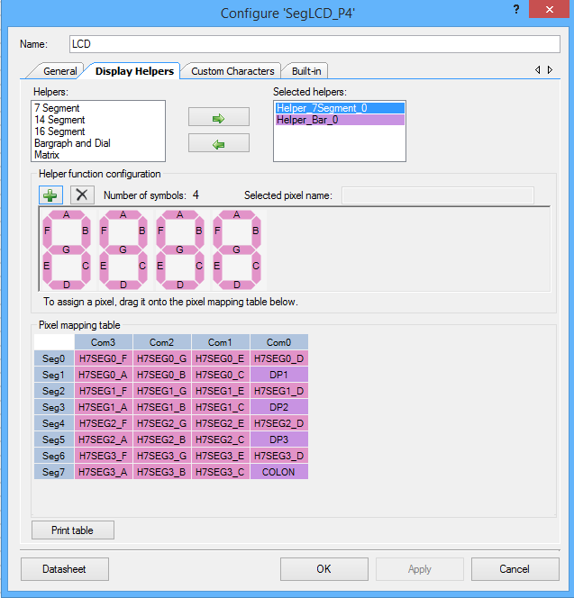
To configure the component display you need to first add a “7 segment” helper to your component by selecting it and then clicking the right arrow.  Then you click the “+” 4 times to add 4 digits to your design.  Then you need to drag and drop the each segment from the digits onto the correct location on the segment/common matrix in the “pixel mapping table”.  For example “Common 3 / Segment 1” or “C3/S1” is the top segment in the left digit (look at the picture above), it needs to go in the “Com3” column and the “Seg1” row.  There is a pattern and once you see it this will not take very long.

Screen Shot 2016-05-24 at 8.40.52 AM

The next step is to add the decimal points and colons to your project.  To do this add a “barograph and dial” helper.  Then click the “+” 4 times so that you have 4 segments.  As you add each one give it an appropriate name e.g. “colon” or “dp1”

Screen Shot 2016-05-24 at 8.41.05 AM

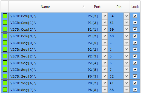
The last thing that you need to do is to assign the pins.

Screen Shot 2016-05-24 at 9.16.50 AM

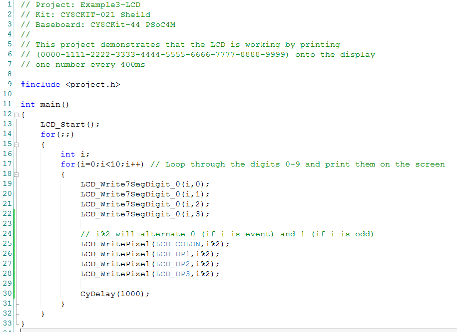
The firmware is simple:

Screen Shot 2016-05-24 at 9.25.13 AM

Example 4: The Potentiometer

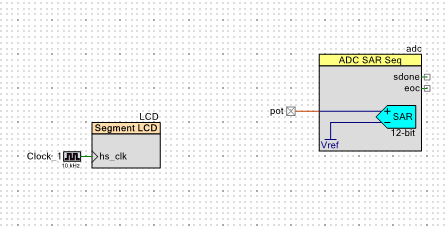
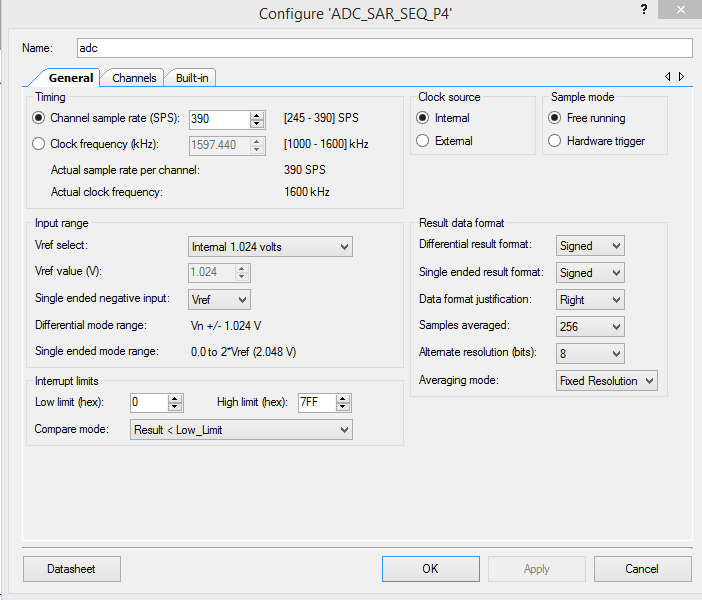
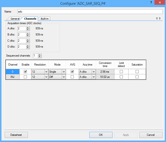
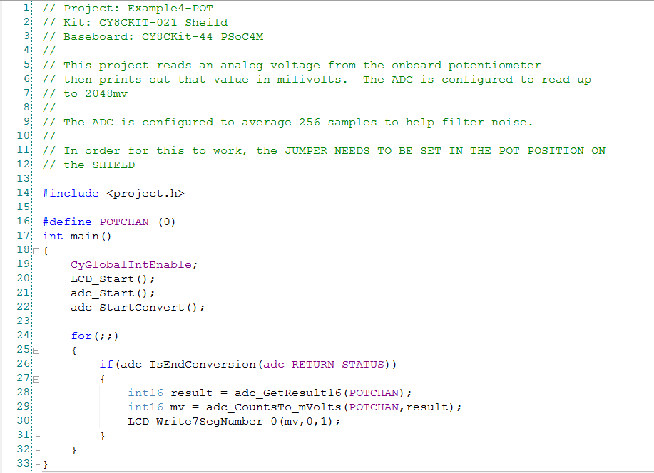
To test the potentiometer I will use the ADC to measure its output voltage and then display it on the LCD screen.

Screen Shot 2016-05-24 at 9.50.55 AM

Screen Shot 2016-05-24 at 9.51.39 AM

Screen Shot 2016-05-24 at 9.51.51 AM

Screen Shot 2016-05-24 at 9.52.11 AM

I am out of time… so in the next post Ill show examples 5,6,7

Alan

index description
CY8CKIT-021: A Simple FM/PSoC + BLE Demonstration Board Introduction to CY8CKIT021
CY8CKIT-021: The first four example projects Use the LEDs Buzzer 7-Segment display and the Potentiometer
CY8CKIT-021: The next three example projects Use theThermistor and two Capsense Examples
CY8CKIT-021: Bootloading the PRoC How to put firmware into the PRoC
CY8CKIT-021: The BLEIOT Component A custom component to communicate with the PRoC/PSoC
CY8CKIT-021: Using the BLEIOT Component A full example of the tho MCUs talking
CY8CKIT-021: The PRoC BLE Firmware How to make PRoC Firmware and use it with the BLEIOT Component
CY8CKIT-021: Example 10 - the new IOS App How to build and IOS App to talk to the development kit

CY8CKIT-021: A Simple FM/PSoC + BLE Demonstration Board

In my job I spend a lot of time teaching people how to use Cypress Products.  One of the best students that I ever had was Paul Bentley the Cypress VP of Sales for Europe.  He came to Kentucky a few years ago to take my class.  He dove in with reckless abandon and did a amazing job learning how to actually program the PSoC (not just talk about it on powerpoint).  Recently, he was anointed with the responsibility to teach more of our Sales team to use PSoC at the Sales Technical Conference (STCON) which is going on this week.

For some time I have wanted a very simple, inexpensive board to help teach people how get going using our chips…. all of our chips both the FM products as well as the PSoC products.  The STCON afforded the perfect opportunity to build an education board.  I am very lucky to work with some really good people (in India and New Hampshire) who did the work of realizing the vision of a simple board and getting it made in short time.

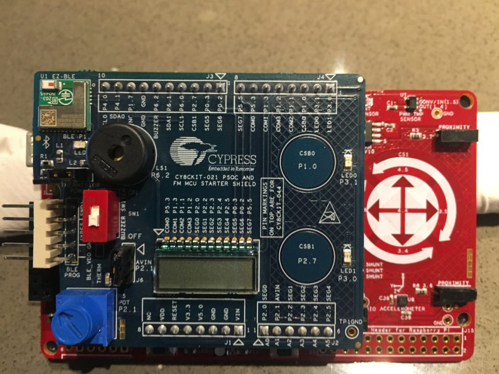
Without further ado, here it is, the provisionally name CY8CKIT-021 PSoC and FM Starter Shield (shown connected to the CY8CKIT-044).

imageThe shield has an Arduino compatible footprint and has:

  • 2 CapSense Buttons
  • A Potentiometer
  • A Thermistor
  • 2 LEDs
  • A PRoC BLE Module
  • A Piezo-electric buzzer
  • A 7 Segment direct drive LCD

The PRoC is connected to the USB-I2C bridge on the programmer as well as the serial (I2C/UART) pins on the base board.  Here is the schematic:

Screen Shot 2016-05-23 at 6.53.13 AM

One of the cool things about this board is that it is generally compatible with a bunch of the Cypress products including:

  • CY8CKIT-042
  • CY8CKIT-042-BLE
  • CY8CKIT-044 (which is shown in the picture above)
  • CY8CKIT-046
  • S6E1B8
  • S6E1C3

Over the next several days I am going to show you example projects using the board.  I will culminate at the end of the week by IOTifying the board by writing BLE firmware for the PRoC, building an IOS app and an Android app to talk to the board.

index description
CY8CKIT-021: A Simple FM/PSoC + BLE Demonstration Board Introduction to CY8CKIT021
CY8CKIT-021: The first four example projects Use the LEDs Buzzer 7-Segment display and the Potentiometer
CY8CKIT-021: The next three example projects Use theThermistor and two Capsense Examples
CY8CKIT-021: Bootloading the PRoC How to put firmware into the PRoC
CY8CKIT-021: The BLEIOT Component A custom component to communicate with the PRoC/PSoC
CY8CKIT-021: Using the BLEIOT Component A full example of the tho MCUs talking
CY8CKIT-021: The PRoC BLE Firmware How to make PRoC Firmware and use it with the BLEIOT Component
CY8CKIT-021: Example 10 - the new IOS App How to build and IOS App to talk to the development kit

Maker Faire – Bay Area

IMG_2820

I am at the Maker Faire this weekend teaching people how to  program the PSoC.  We have a bunch of computer runnings PSoC Creator and I am giving out development kits.

Come to the Cypress booth and signup and I will teach you!

https://twitter.com/CypressSemi/status/734155415928217601

https://twitter.com/CypressSemi/status/734142119779000320

https://twitter.com/CypressSemi/status/734138496068124672

https://twitter.com/CypressSemi/status/734131371971469312

https://twitter.com/CypressSemi/status/734127268495134720

https://twitter.com/CypressSemi/status/734124734451843072

https://twitter.com/CypressSemi/status/734082357171363841


The Creek: Install the Raspberry PI Software

Years ago, when I did the first install of a Raspberry Pi (RPi), this whole thing was quite painful, however at this point the installation process is well documented.  In addition adafruit.com has a nice tutorial about making the I2C work here.

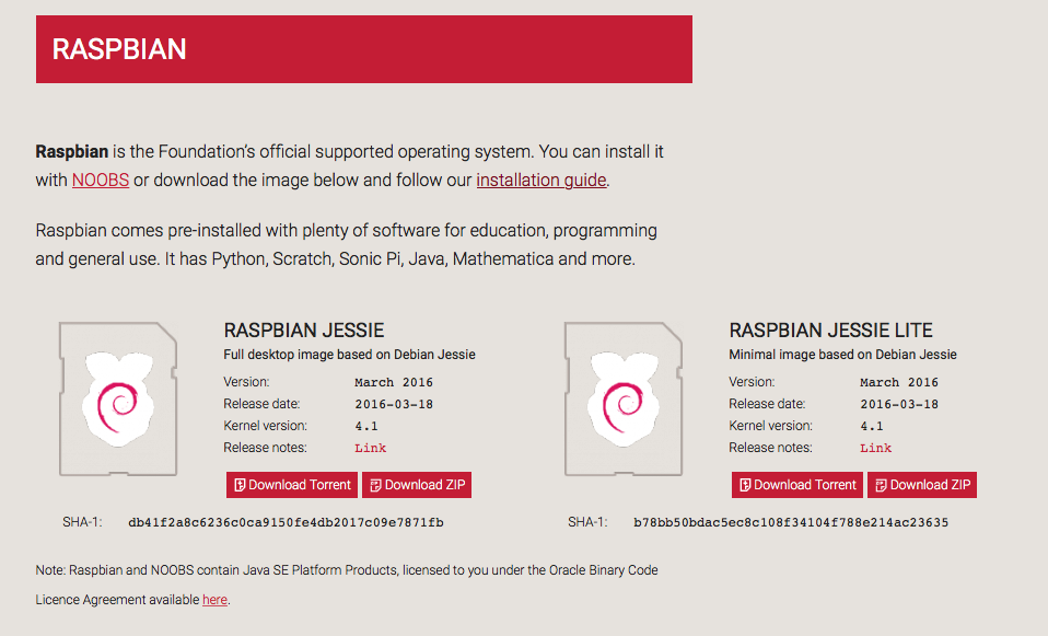
To start the process download the Raspbian image from it from here.

Screen Shot 2016-04-02 at 8.50.41 AM

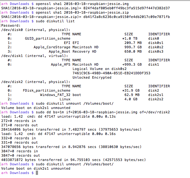
Because I talked so much about security in this post, I thought that I had better check the cryptographic hash.  So, I run

  • openssl sha1 2016-03-18-raspbian-jessie.img

And I get:

SHA1(2016-03-18-raspbian-jessie.img)= 824f4daf805eb0ff49bc3fa515d97f447d382d37

which definitely didn’t match the signature, so now what? Is this a hack?  It turns out that my Mac “helps” you by unzipping the file.  The cryptographic hash of a file and a zip of that file are different.  If you download the zip and run the hash you will get:

SHA1(2016-03-18-raspbian-jessie.zip)= db41f2a8c6236c0ca9150fe4db2017c09e7871fb

OK.  They match.  Good.  The next step is to write the image to the flash card.  To do this

  • Insert the card (into your Mac)
  • See what disks are mounted
  • Unmount the volume (if you already had something on the card)
  • Write the image onto the flash card.  In the instructions on the Raspberry Pi site there is some confusion about if you should use /dev/rdiskx or /dev/diskx.  Thats simple, you should use the “r” version.  “r” stands for raw and is unbuffered and as such is much faster to write.  Even with the raw device it still takes a few minutes.  While it is writing you can press “ctrl-t” and it will give you a status (which I did twice during the write process)
  • Unmount the disk

Screen Shot 2016-04-02 at 9.20.38 AM

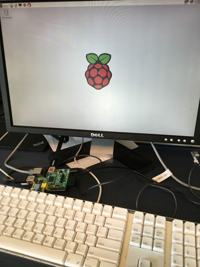
Now that you have a bootable flash disk your next step is to insert the card into your RPi, attach a keyboard, the network cable and a screen.  Then boot it.  After a few minutes you should see:

IMG_2768

The first thing that needs to be done is to change the password and expand the filesystem.  To do this run “sudo rapsi-config” then select

  • [Option 1] Expand Filesystem
  • [Option 2] Change User Password

I prefer to interact with the RPi using secure shell from my Mac.  To do this I need to know what IP address was assigned by my DHCP server.  So, start a terminal on the Pi and type:

  • ifconfig (find the ip address and the ethernet mac address)

Once I know the ethernet mac address I can configure my DHCP to always give this Raspberry Pi the same IP address.  You can read more about this in the “Creek Network” post.  For now I will assign the RPi the address 192.168.15.82 and I will add that address to the /etc/hosts file on my Mac so I can refer to it by the name “iotexpertrpi”

Now that all of the networking is setup, reboot.  As I have configured the IP address I can now log in using secure shell and start the configuration process.

  • [from the Mac] ssh pi@iotexpertpi (you will need to type the password which is “raspberry”)
  • [on the pi] mkdir .ssh
  • [on the pi] chmod 700 .ssh
  • [on the pi] exit
  • [from the Mac] cd ~/.ssh
  • [from the Mac] scp id_rsa.pub pi@iotexpertpi:.ssh/authorized_keys (you will need to type the password)

Then, to test SSH I will exit and log back in.  After the secure shell is going I need turn on the stuff in the configuration that enables I2C.

  • [on the pi] sudo apt-get install i2c-tools

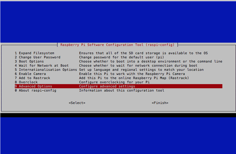
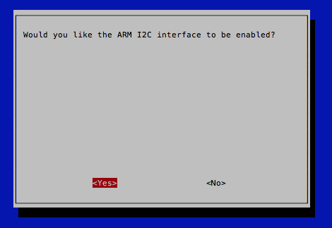
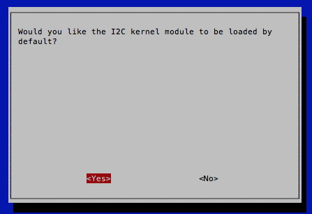
In order for the I2C work you also need to enable the kernel drivers for I2C.  To do this run “[on the pi] sudo raspi-config”

Screen Shot 2016-04-02 at 9.53.12 AM

Screen Shot 2016-04-02 at 9.53.25 AM

Screen Shot 2016-04-02 at 9.53.39 AM

Screen Shot 2016-04-02 at 9.53.52 AM

After I2C is setup I will change the RPi to not start X-Windows.

Screen Shot 2016-04-02 at 9.56.10 AM

Screen Shot 2016-04-02 at 9.56.22 AM

After all of that, reboot the RPi and see if things are working.

  • [on the Mac] ssh pi@iotexpertpi
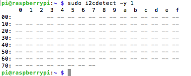
  • [on the pi] i2cdetect -y 1  (the 1 means bus 1.  On the Broadcom chip there are 2 IC Masters which they have labeled 0 and 1.  Apparently they did not connect Master 0 to anything)

This is good.  I can “search” all of the addresses.  Basically the RPi tries to write each address.  If it gets an “ack” then it will indicate that on the chart with a number.  In the picture below you can see that there are no I2C devices attached to the bus.

Screen Shot 2016-04-02 at 10.09.41 AM

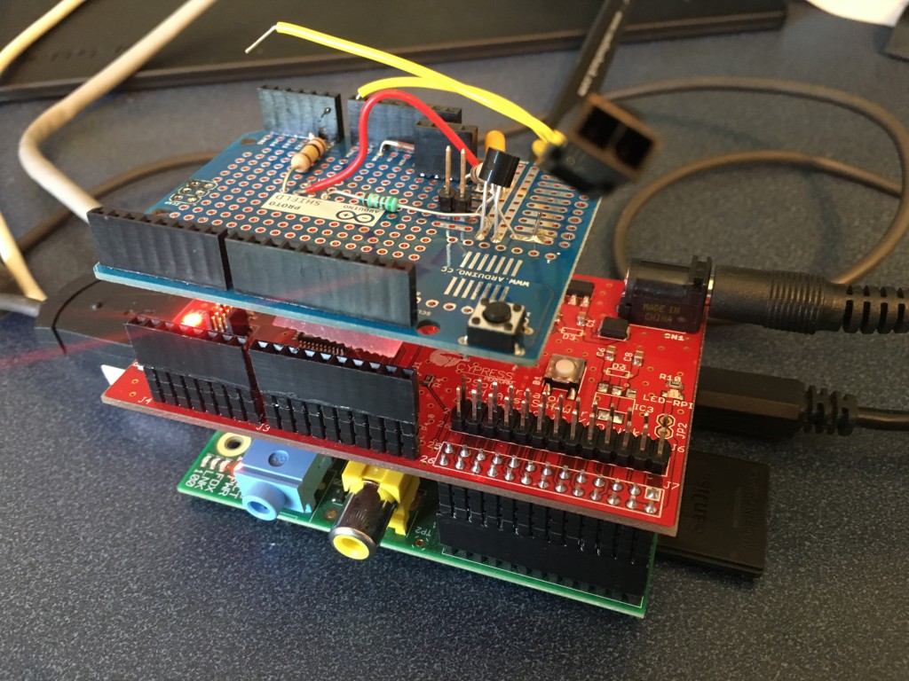
Everything looks good.  Halt the RPi then attach the CYPI board and reboot.

IMG_2770

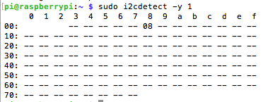
Now, when I log back in and run “i2cdetect -y 1” lookey there, the CYPI “ACKs” on address 08.

Screen Shot 2016-04-02 at 10.27.45 AM

If you remember in this post I talked about the I2C register structure of my Creek Firmware.  In the two bytes starting at location 2, is a 16-bit integer of the temperature times 100 (I just noticed the error in my comment, bad Alan).  Here is the register structure:

DataPacketFormat

In I2C tools, the command “i2cget” can read bytes or words from an I2C Slave.  Are things working?  Run “i2cget -y 1 8 2 b” and “i2cget -y 1 8 2 b” and I get 0x10 and 0x09 or 0x0910 (remember that the data is stored little endian) which is 2310 in decimal or 23.1 degrees C.  That makes sense.  What is a bit confusing is when I read a whole word by changing the “b” to “w” it gives it to me correctly because it ASSUMES little endian, so be careful if your slave device doesnt store thing little endian.

Screen Shot 2016-04-02 at 10.39.32 AM

Everything seems like it is working.  In the next posts I will discuss the installation of the MySql, Tomcat and the rest of the server software.

Index Description
The Creek: IOT for the Elkhorn Creek Introduction
The Creek: Solution Architecture 1.0 Overall architecture
The Creek: Creek Board 1.1 Eagle layout of the board
The Creek: Creek Board 1.0 – RCCA A discussion of the errors in the 1.0 board
The Creek: CYPI, a Raspberry Pi to Arduino Bridge PSoC4 <--> Raspberry Pi Bridge Board
The Creek: PSoC4 Creator Schematic and Firmware Firmware to interface with the temperature and pressure sensors
The Creek: Testing the Firmware Using tools to verify that the PSoC 4 Firmware is working correctly
The Creek: Testing the Bootloader Make sure that you can load new firmware into the PSoC
The Creek: Software Architecture All of the Raspberry Pi software connections
The Creek: Install MySql Instruction to configure MySql
The Creek: Install Tomcat Instruction to configure Tomcat JSP Server
The Creek: Data Collection Java (Part 1) The Java program that reads the I2C and saves it in the database
The Creek: Data Collection Java (Part 2) The Java program that reads the I2C and saves it in the database
The Creek: Create the Chart with JFreeChart Using open source Java charting software to create plots of the Creek Depth
The Creek: Flood Event Data Processor A batch program to create analyze the database and create a table of flood events
The Creek: Flood Event Web Page A batch program to create the flood event web page
The Creek: Creek Server 1.1 Updates to all of the back off server programs to integrate charts
The Creek: JSP Web Page for www.elkhorn-creek.org The JSP program to make the table and display the website
The Creek: Raspberry Pi Clock Stretching Sorting out a bug in the system having to do with the Broadcomm Raspberry Pi Master not functioning well with clock stretching
The Creek: Creek Server 1.2 Caching the web pages to make them faster

The Creek: Meraki Network

I have very mixed emotions about posting a diagram of the network at my house.  On one hand the network is super cool and lets me do all kinds of interesting things so I think a lot of people will be interested in it.  On the other hand giving information that could be used by hackers might not be such a good idea.  I don’t think I am giving away to much crucial information, but I don’t know that to be the case.

OK.  Here it is.  I use a bunch of Meraki networking equipment from Cisco.  Meraki is a cloud managed infrastructure company that was bought by Cisco in 2012.   Cisco seems to position it for smallish companies who need first class networking but don’t have lots of people to support it.  Cisco handles all of the patching, network maintenance, etc. but you still have complete control to do about whatever you want.  In my case, it can do more things that I am capable of doing.

I wanted a network that could:

  • Provide a wide physical area of WiFi coverage (I live out in the country in lots of space)
  • Provide private and public WiFi on separate VLANs
  • Wirelessly extend both the WiFi and the ethernet network into the barn
  • Traffic shape all of the networks onto the Internet
  • Manage my children access to the Internet
  • Provide excellent firewall services

I have a close friend who works at Cisco as an Application Engineer who convinced me to choose Meraki.  Overall I am sure that there is a premium that you need to pay, but it works great and is easy to learn and administrate.

First the physical diagram:

meraki-physical-a

The MR60W was designed to be a complete small office solution.  It has

  • 5 ports of 1G ethernet
  • WiFi (Both 5G Hz and 2.4GHz)
  • Firewall
  • Connection to Internet

The MR60W has been superseded by the MR64W, Cisco appears to have removed the MR60W product landing page from their website or I would have linked to it, but I did find a review here.  They call this the “security appliance” as it is the principal device in securing your network.

The MS22P (which has also been obsoleted) is a 24 port, power-over-ethernet, gigabit ethernet switch.  It supports all of the switching things that I needed to do to have separate VLANs.  This looks like it has been replaced by the MS220-24.  In my office I have several devices that I run on wired ethernet including a couple of MACs, and a 17TB dual ethernet Segate RAID box.

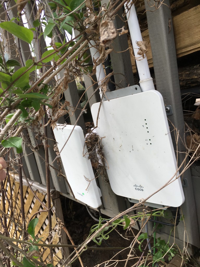
The MR66s are outdoor access points that I use to

  • Bridge between the Barn and my house (they have Yagis)
  • Provide Wifi in the barn and around the back of my house
  • Provide ethernet in the Barn

This is a picture of the access point attached to the side of my porch.  You can see the Yagi antenna on the left.

IMG_2781

This is a picture of the “other end” of the bridge.  The Yagi points towards my house and the other Yagi.

IMG_2783

The MR16 is is a WiFI access point (that has been superseded by the MR18).  It is located in the far corner of my upstairs and provided Wifi for the front part of the house.  It runs off of Power-over-Ethernet (which made it easy to install).

Configuration

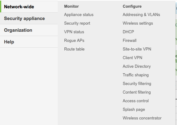
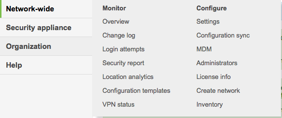
When you enter the Meraki control website there are an unbelievable number of configuration and monitoring screens that you have access to.  Here are a few of the menus:

Screen Shot 2016-04-07 at 5.39.04 AM

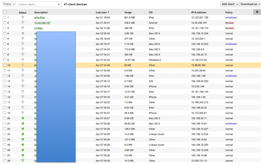
The “Cients” menu give you this screen where you can monitor the clients that are accessing your network and whitelist or blacklist them.  Notice that I have two unknown people who joined the guest network blocked (probably the neighbors kids).

clients

This menu gives you access to all of the configuration settings of your network including VLANs, Wireless network, DHCP etc.  The system will also allow you to create VPN tunnels between offices.

Screen Shot 2016-04-07 at 5.39.13 AM

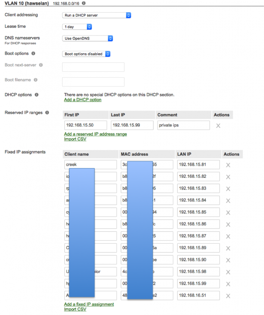
Here is the DHCP screen.  You can see that I have a number of “fixed” IP assignment based on ethernet mac addresses.

dhcp

This menu has global settings about your network, for instance the Administrators menu where you can configure everyone who is allowed to log into the management web page.

Screen Shot 2016-04-07 at 5.39.22 AM

This menu allows you to control the switches on your network.

Screen Shot 2016-04-07 at 5.39.52 AM

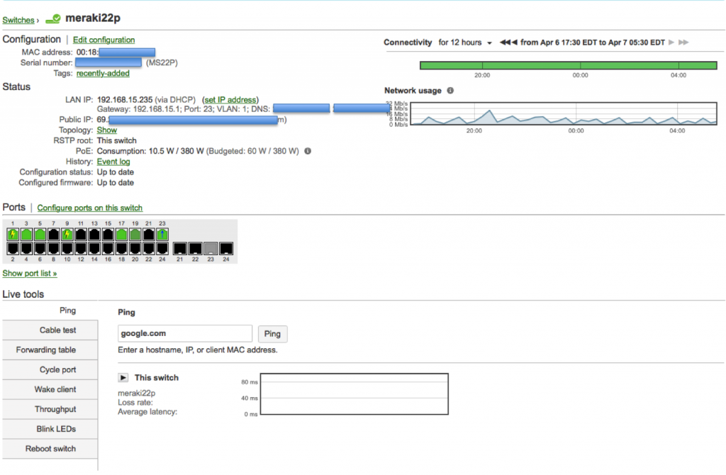
Here is a screenshot of the MS22P Ethernet Switch:

m22p

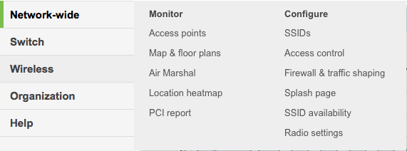
This menu allows you to control your wireless networks.

Screen Shot 2016-04-07 at 5.40.00 AM

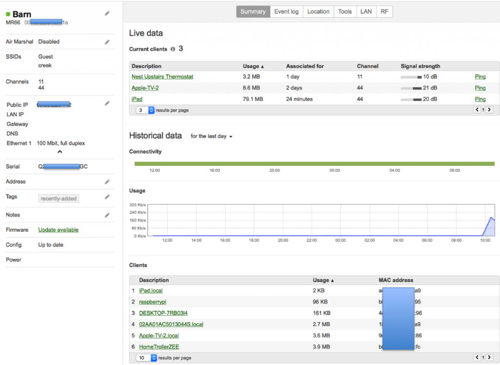
Here is the screen that shows the status of one of the WiFi Access Points

mwireless

All in all the network works very well.  Send me an email or leave a comment if you have a question.

Git and SSH

Summary

In a previous post I talked about the steps I took to repurpose my old Mac Mini as a server.  In this post I will explain the steps that I went through to make it act as a “Git” server.  Although I am an active github.com user it is sometimes nice to have something stored locally as well.  The easiest (and best) way to make a git server on your network is to use SSH.  In order to make SSH work you need to know about encryption and keys.  I knew in an abstract way about encryption but I hadn’t really dug through how all of the parts operate in detail which I had to do to figure this out.  I will start by explaining the practical mechanics of encryption, and then take you through the rest of the steps to setup and use Git.

  1. Symmetric and Asymmetric Encryption: A Foundation
  2. Setup Git as user on your Server
  3. Create RSA Keys for a User
  4. Give user permission to write into Git User Account
  5. Create a new repository called “repoName”
  6. Using the new repository

Symmetric and Asymmetric Encryption: A Foundation

SSH stands for Secure SHell.   The reason it is called Secure is that it uses an encrypted channel for all communication.  But how can that be?  How do you get a secure channel going?  And what does it mean to have a secure channel?  What is secure?  This could be a very complicated topic as establishing a fundamental mathematical understanding of encryption requires competence in advanced mathematics that is far beyond most everybody on the face of this planet.  It is also beyond what there is room to type in this blog.  It is also far beyond what I have the ability to explain.  But, don’t despair.  The practical aspects of getting this going are actually pretty simple.

First a word of caution.  When you make the changes to your computers/network to make this stuff work, you are playing with fire.  If you are not careful, you will compromise the security of your system.  At this point all of the computer and operating system vendors have spent considerable amounts of time and money making computers safer by installing firewalls and closing security holes.  For as much as they have spent making security, the fucking hackers, the Chinese government and the assholes in US government have put 10x that energy into trying to steal your information.

All encryption does the same thing.  It takes un-encrypted data, combines it with a key, and runs it through an encryption algorithm to produce encrypted data.  You then transmit the encrypted data over the network.  When the other side receives the data it decrypts the encrypted data by combining it with a key, and running the decrypt algorithm.

There are two types of encryption schemes, symmetric and asymmetric.

Symmetric means that both sides use the same key.  That is, the key that you encrypt with is the same as the key you unencrypt with.  Examples of this type of encryption include AES and DES.  This type of encryption is preferred because it is very fast and secure.  However, both sides need to know the key before you can use it.  If you have never talked before how do you get both sides to know the key?  This is a big problem.

Asymmetric, often called Public Key, encryption techniques use two keys that are mathematically related.  The keys are often referred to as the “public” and the “private” keys.  The private key can be used to decrypt data that the public key encrypted and vis versa.  This is super cool because you can give out your public key to everyone, they can encrypt data, then only your private key can be used to decrypt it.  The problem with this encryption technique is that it is slow.

What now?  The most common technique to communicate is to

  • You open an unencrypted connection to a server
  • You give out your public key to the server
  • The server then creates a random symmetric key
  • The server then encrypts its newly created random symmetric key using your public key and sends it back to you
  • You use your private key to decrypt the symmetric key
  • You open a new channel using symmetric key encryption

public-key-exchange

This scheme is completely effective against eavesdropping.  What happens if someone eavesdrops the original public key?  That is OK because they won’t have the “client private key” required to decrypt the symmetric key.  What this scheme doesn’t work against is called man-in-the-middle (MIM).  An MIM attack works by

  • You open an unencrypted connection to a server [but it really turns out that it is a MIM]
  • You send your public key to the MIM
  • The MIM opens a channel to the server
  • The MIM sends its public key to the server
  • The Server encrypts a symmetric key using the MIMs public key and send it back to the MIM
  • The MIM decrypts the symmetric key using its private key
  • The MIM send you the symmetric key encrypted with your public key
  • You unencrypt the MIM symmetric key using your private key
  • Then you open new channel to the MIM using the symmetric key
  • The MIM opens up a channel to the server using the symmetric key

Once the MIM is in the middle it can read all of the traffic.  You are only vulnerable to this attack if the MIM gets in the middle on the first transaction.  After that things are secure.  However, the MIM can easily happen if someone gets control of an intermediate connection point in the network-like e.g. WIFI access point.  The only way to protect against MIM attacks is to have a Certificate Authority (CA).  A CA works by verifying that the Public Key actually belongs to who you think it belongs to by using a cryptographic hash.  If the MIM sends you its public key then you check with the CA and find out that the MIM public key does not belong to the server that you are trying to connect to, then you know that you are being subjected to an MIM attack.  How do you prevent an MIM when talking to a CA?  This is done by building in known valid certificates into your program.   This morning when I looked at the certificates on my Mac there were 179 built in, valid certificates.  This is cool for HTTPS but what about SSH?  With SSH you will need to manually verify the public key of the host you are attaching to.  There is a nice discussion of this topic here.

When you configure your GIT server you will manually copy your public keys onto the GIT server.  This will prevent MIM attacks and will support the establishment of a symmetric encrypted connection.  This is called an out-of-band (OOB) key exchange.  On github this is done with a browser.   For other security systems it could be a USB stick or other scheme.  More on that later.  Now onto the mechanics of making the Git server work.

Setup Git as user on your Server

First you need to enable Remote Login (ssh) from the System Settings –> Sharing.  Make sure that it enabled for All Users
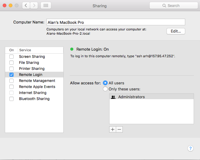
Remote Login

Then you need to turn on the firewall  System Settings –> Security & Privacy
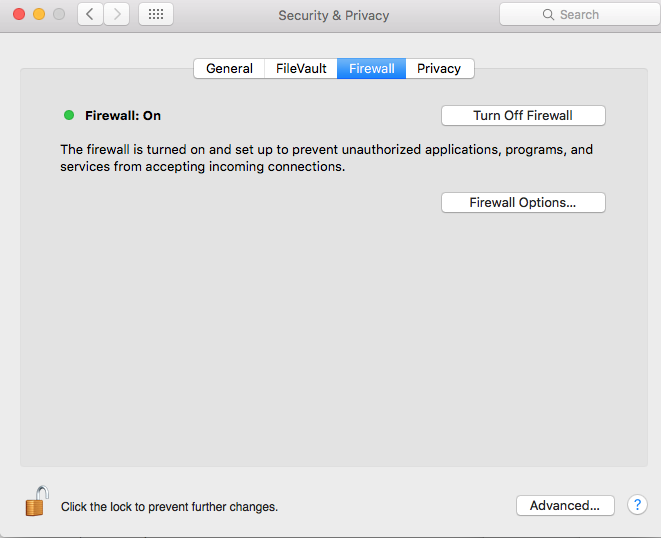
Firewall

Press the “Firewall Option…” turn off the “Block all incoming connections” and then allow Remote Login (SSH)
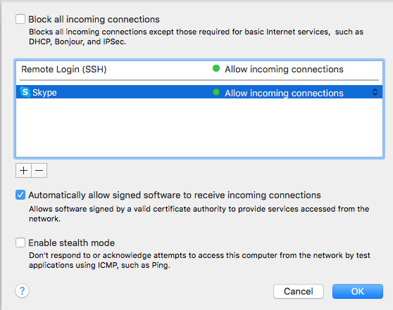
Firewall Remote Login

Then you need to create a “git” user account.  The account should be a standard account.
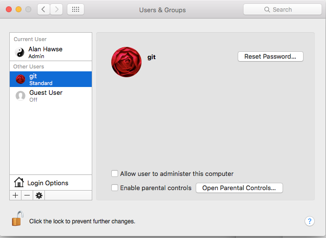
Create GIt Account

The next step needs to be done in a terminal window.  You need to have root access (your account need to be authorized as an administrator) to follow these steps.  This will create the place to store the SSH RSA Keys.

command comment
su – git log in a the git user.  You will need to type the password that you set when you setup the git account
mkdir .ssh Create the directory with the public and private secure shell keys
chmod 700 .ssh This directory should only be redable by the git user
cd .ssh
touch "authorized_keys" Create a file that you will add public keys to of the people who are allowed to upload to this server
sudo chpass -s /usr/bin/git-shell git Make the git user so that it can only do git commands.  This is a way to enhance security by not letting the git account do anything other than local git commands.

Create RSA keys for a user

In order for a user to have access to the git account on the server he will need to have RSA Keys.  Specifically, in the ~/.ssh directory of the user you will need two files, id_rsa and id_rsa.pub  These files are the public and the private keys of the user.  When you run the command

  • ssh-keygen -t rsa -b 4096 -C “user@computer”

it will first ask you where to store the keys.  If you already have keys it will give you the option to store them someplace other than the default location.  Then ssh-keygen will ask you for the password to encrypt the private key file.  I don’t use a password on my private key file, but the security would probably be better if I did.  The “-C” option just inserts the text in quotations into the key file as a comment so that when you look at the file you can figure out what the key is associated with.
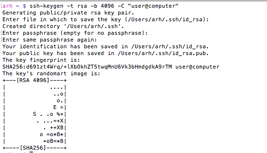
Screen Shot 2016-03-29 at 7.24.22 AM

You can look at the MD5 signature (which is what github displays) of a public key by running

ssh-keygen -E md5 -lf  id_rsa.pub

Give user permission to write into your Git User Account

In order for a user to be able to access the git server you will need to append his public key to the “~git/.ssh/authorized keys” file.  As I talked about above, in the users home directory you will find a directory called “.ssh”.  In that directory there will be two files, one is called “id_rsa.pub” which is the RSA public key, the other is called “id_rsa” which is called the private key.  You should be very careful to only copy the public key.

  • sudo cat id_rsa.pub >> ~git/.ssh/authorized_keys

In this example both users were on the same computer, but they don’t have to be.  In that case you will need to copy the file some other way (ftp, scp, the browser, …)  Then append it to the ~git/.ssh/authorized_keys file.

Create a new repository called “repoName”

Once you have everything setup with the git user and the SSH RSA keys you will need to create a “bare” repository

  • cd ~git
  • sudo git init –bare repoName.git
  • sudo chown -R git repoName.git

Using your new repository

The last thing to do is to setup git remotes for the new repository.  To do this, on your client machine you can either clone it with

  • git clone git@githost:repoName.git

Or if you have an existing repo you can

  • git remote origin git@githost:repoName.git
  • git push origin master


Other random topics

When I was trying to figure out how all of this worked I found a couple of places (on google) that talked about modifying the file /etc/ssh/sshd_config.  This turned out to be a red herring as the default Mac OS X settings work fine.

When you open a new shell on your client computer, then start your first SSH, the client shell automatically starts a daemon called “ssh-agent”.  This daemon reads all of your key information and caches it.  You can see the information that it is storing by running “ssh-add -l”.  If for some reason you change your rsa keys you will need to either restart the daemon or tell it to read the new keys “ssh-add ~/.ssh/id_rsa”.  You can read more about this in these articles ssh-agent-forwarding and ssh-agent-keys in the github documentation.

If for some reason you are using multiple rsa key files then you need to create a “~/.ssh/config” file to setup which key is used in which situation.  I have this situation because I use github for my personal stuff as well for my iotexpert stuff.   By default ssh uses the keys in “~/.ssh/id_rsa”.  If you need to setup a different key for other hosts you can:

  • Create an ssh name called “github.com” which uses “~/.ssh/id_rsa”
  • Create and ssh name called “iotexpert.github.com” which uses “~/.ssh/id_rsa_iotexpert”
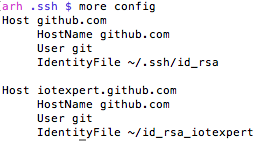
Screen Shot 2016-03-30 at 7.14.13 AM

There is a daemon running called the ssh-agent.  It is used to cache and deliver the keys.  You can see what keys it knows about by running

ssh-add -L

You can delete the cache by running

ssh-add -D

You can add keys to the cache by running

ssh-add ~/.ssh/id_rsa

ssh-add ~/.ssh/id_rsa_iotexpert

To test all of this (with github) you can run

ssh -T git@iotexpert.github.com

or

ssh -T git@github.com

These commands will test the key exchange to make sure that the right key is being mapped to the correct user.

Then to setup the different remotes I do

  • git remote add origin git@github.com/someuser/repository.git to use the id_rsa key
  • git remote add origin git@iotexpert.com:iotexpert/repository.git to use the id_rsa_iotexpert key

The thing that was intensely confusing is “iotexpert.github.com” isn’t actually the name of a computer.  It is just an ALIAS that ssh uses… when SSH runs it looks in the config file and if it sees a “Host” alias that matches what you typed, then it substitutes the value of “HostName” in place of where you gave it “Host”.
 

Mac Mini –> Mac Server

In 2011, I bought a Mac Mini Server to act as my main desktop.  That computer had 2GBs of RAM and 2 internal 500gb hard drives.  I originally setup that computer as RAID1, meaning that the two drives were in a mirror configuration.  This meant that if one failed that I didn’t loose my data and things kept going.  As I am paranoid about my data I also had a Time Capsule that made regular backups using Time Machine.  I will admit that I am an Apple fan boy.  When I got married in 1992 the asshole photographer misprocessed the film, which resulted in all of the pictures being destroyed.  Since then, I have been really really paranoid so I also backup my backup to the Cloud using Mozy.

In the fall of 2014 I switched to using a MacBook Pro as my main computer, so I moved the Mac Mini onto my kids desk.  And, as computers seem to do, the Mac Mini became slower and slower as more crap was loaded onto it.  Earlier this year I bought them a new Mac Mini and set my old workhorse to the side.   About 6 weeks ago, I decided that I was interested in building a new cloud server and I decided to refurbish the Mac Mini as a server.

I started the process by installing two 8 GB SIMMs which I bought from MacSales.com because they have really excellent tutorials on their website.  16GB made a huge difference in the performance of the machine.  The install process is pretty simple.  The Mac just has a cover which twists off giving access to the two SIMM slots.  Here is the video tutorial that they provide

https://player.vimeo.com/video/139638226?title=0&byline=0&portrait=0

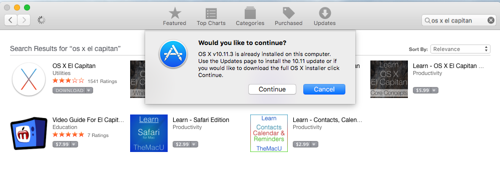
I then reinstalled the OS, which was a total pain in the neck.  At some point in the last couple of years Apple stopped delivering an operating system DVD, moreover I wanted to make a clean install of the most recent version of the operating system and I wanted a backup.  I found the instructions for creating a USB stick on Apples website.  The problem was I didnt have the directory /Application/Install OS X El Capitan.app.  Now what?  After a bunch of google and false starts I figured out that you have to download it from the Appstore, even if you already have it installed on your computer.

To create a USB stick with the most recent Mac OS you need to take the following steps.

  • Get the installation for Mac OSX  from the App Store
    • Press “download”
    • When the installation screen starts, use the menu to quit.  If you don’t do this it will try to install the OS on your computer.

PastedGraphic-2

  • Insert a USB stick and start a terminal
    • run the command “sudo /Applications/Install\ OS\ X\ El\ Capitan.app/Contents/Resources/createinstallmedia –volume /Volumes/MacOSX/ –applicationpath /Applications/Install\ OS\ X\ El\ Capitan.app/”
    • The “/Volumes/…” is the path to the USB stick.  You can figure that out using the command “df”
    • When you run the “sudo …” it will ask you for your password, it will then erase the “/Volumes/…”  Make SURE that you don’t erase your hard disk by picking the wrong directory
    • I had an old USB stick and it took a very long time (about an hour) to make the copy

To emphasize, if you don’t quit the installer it will remove the installation directory from the “/Applications/Install…” folder and you will not be able to create the media.

If you don’t want to do this you can use DiskMaker which provides a GUI that does exactly the same thing.  You can find it at http://diskmakerx.com

The next step is to reboot your Mac from the USB Stick.  To do this, reboot and press the “Option” key to start the “Startup Manager”.   I found an Apple Knowledge Base Article with a list of all of the startup commands here.  After the computer reboots run the “disk utility” program to reformat the hard disks.  When I ran the disk utility I found that one of my hard disks was dead.  I guess that it was a good thing that I was running RAID.  I decided to run on just one disk as this computer was going to be used only for testing, so I picked the good disk to reformat and went for it.  After the disk was formatted I quit the disk utility and then continued the Mac OS installation.
With all of that done I found it remarkable how much faster the computer was.   Night and day difference.

Fast forward several weeks.  My experiments with cloud services were turning more serious (there will be a bunch of posts on this topic).  This set me to worrying about the good disk going bad, which would be annoying, but I suppose, not a horrible problem as I had the belt-and-suspenders-setup.  It seemed like installing two SSDs in RAID would make another leap in performance.  So, I went back to macsales.com and bought a pair of 1TB SSDs, the toolkit to install them, and an external USB 3.0 drive enclosure so that I could read data off of the one good drive.  Doing the installation was quite complicated and took me the better part of two hours.  On the macsales.com website there is an outstanding video of the process.

https://player.vimeo.com/video/139637589?title=0&byline=0&portrait=0

After I got the drives installed the next step was to get RAID1 going again.  Unfortunately, Apple in their infinite wisdom has discontinued support for RAID in the diskutility program.  In order to get the RAID working you need to run diskutility from the command line.  To do that:

  1. Reboot the Mac while holding down the option key with your USB stick installed.  If you are using a PC keyboard on your mini then you are out of luck.  Specifically, there is no option key on a PC keyboard and the only way I could get the option to be held down was to use an old Mac keyboard that I had laying around.
  2. When the Install OS screen comes up run the “Utilities -> Terminal”
  3. In the command window run “diskutil appleraid create mirror MyHardDisk JFHS+ disk0 disk1”  This will create a new volume called “MyHardDisk” that is RAID1 (aka Mirror).  Be aware that this ERASES your hard disks so be careful.  There were several discussions I found on this topic on the internet including this one.

For me the last step was to restore my image from the time capsule.  To do that I

  1. Rebooted the Mac and held down the “Command-R” which starts an internet recovery.  I had to do this because my hard disk doesn’t have a recovery partition
  2. Select recover from Time Capsule

There are two troublesome things about what I have done.

  1. Apple seems to be discontinuing their support for RAID which makes me question how good an idea it is to run.  There doesn’t seems to be any support infrastructure so Im not sure how I would know if there was a problem
  2. The first MacOS USB drive I made worked to install the OS.  The second one did not.  After I compared them, the second one was missing a file called “.IAProductInfo”.  I copied that file from the first to the second drive and things started working.  When I googled around I found a couple of references to this problem.  I have no idea why the second install didnt have the .IAProductInfo.

If you have an answer, or an opinion about either of these topics then please email me or leave a comment.

In future posts I will talk about installing VMware, PHP and a bunch of other tools.