In the previous post I talked about the design and test of a matrix of LEDs, specifically a 3×3 matrix. The benefit of the matrix is that you use only sqrt(# LEDs) GPIO pins. For my Pinball machine I am planning on using a 4×4 matrix. There are two problems with this technique:
- You must limit the current through the LEDs so that you do not exceed the maximum current from the GPIO (which has the impact of dimming them)
- You can only select one row at a time (which has the impact of dimming them)
So how do you solve these problems?
Problem 1: Maximum Current
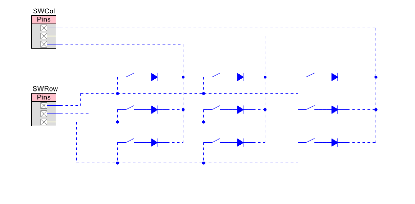
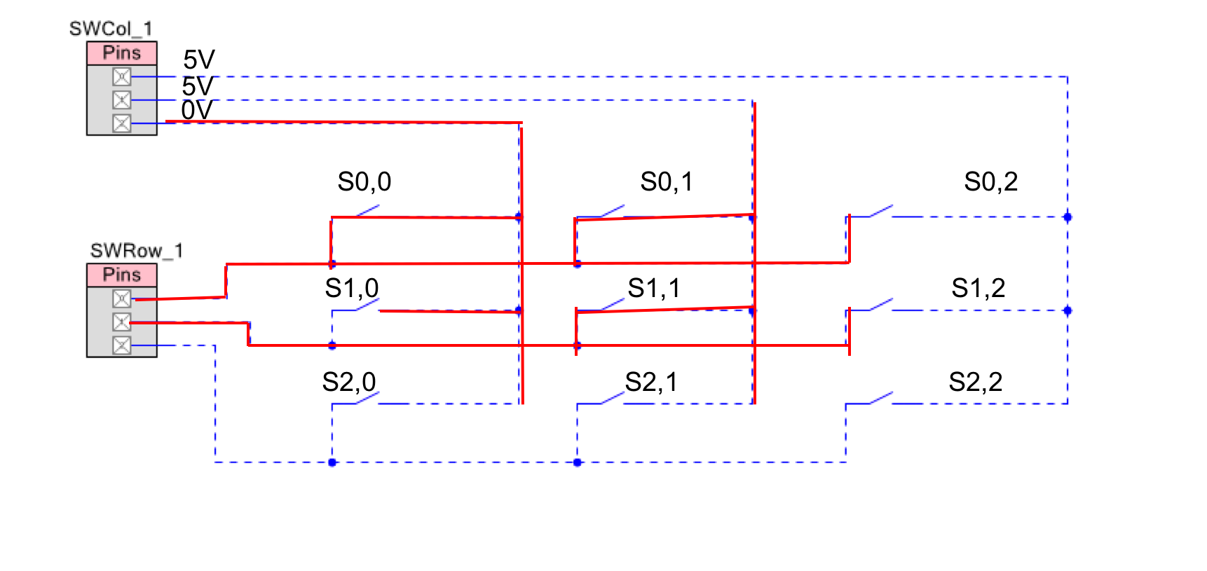
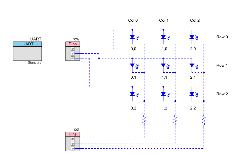
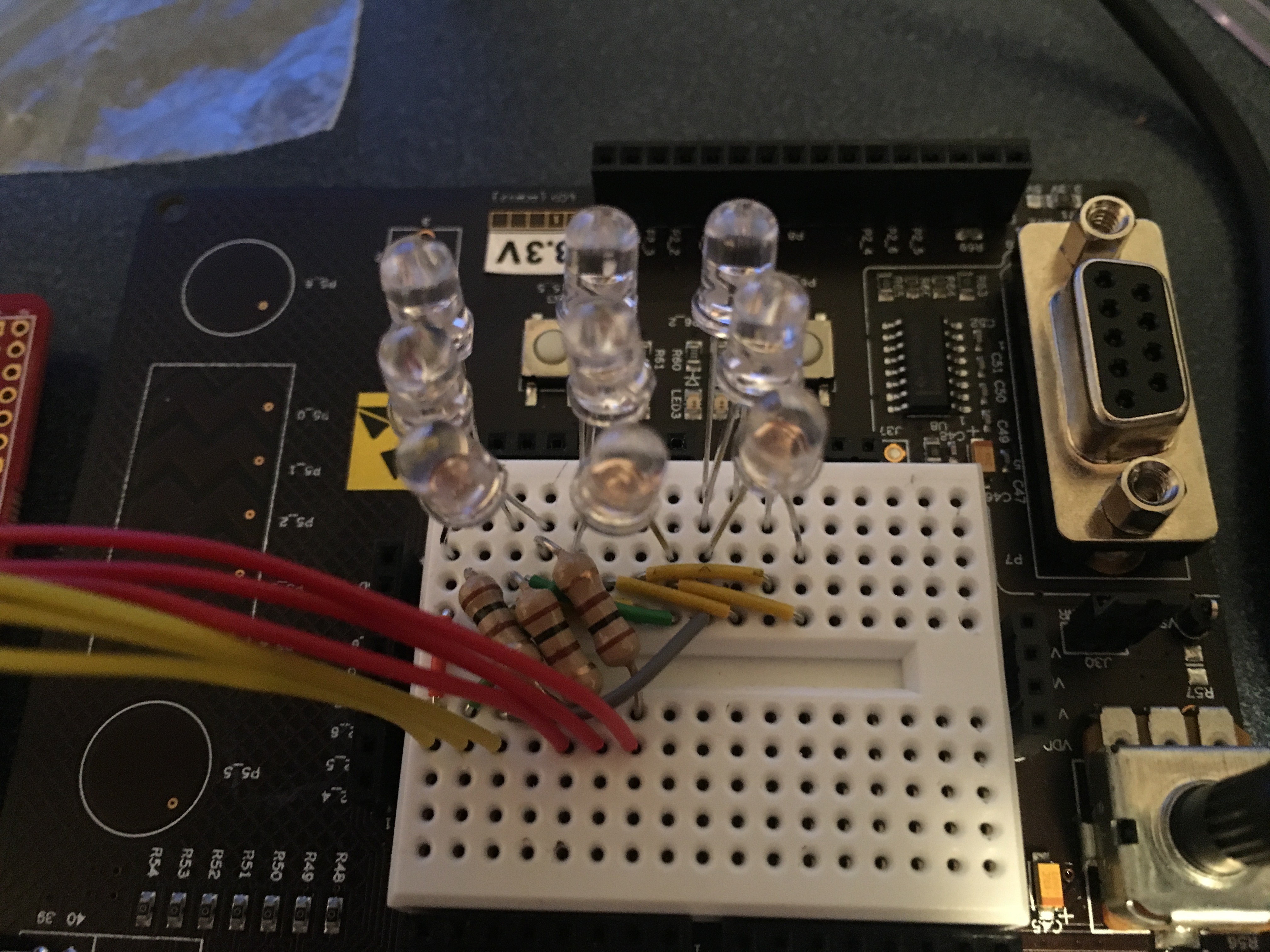
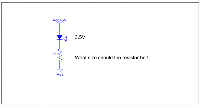
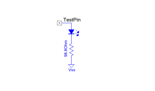
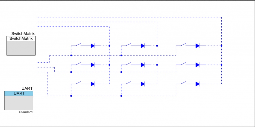
The worst case current occurs when you have one row selected and all 4 columns selected. Here is the equivalent circuit:
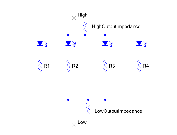
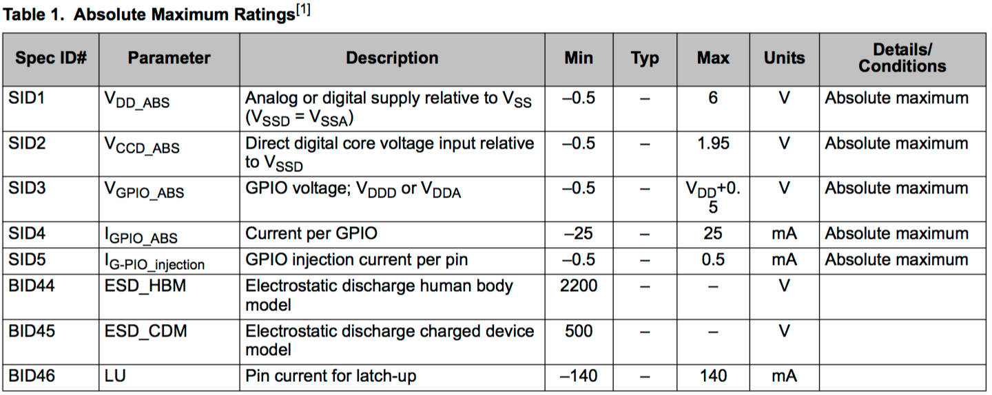
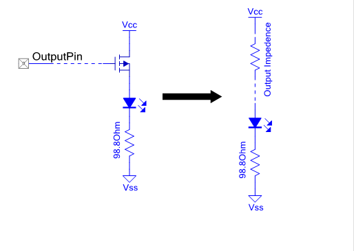
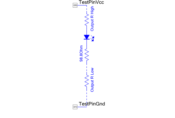
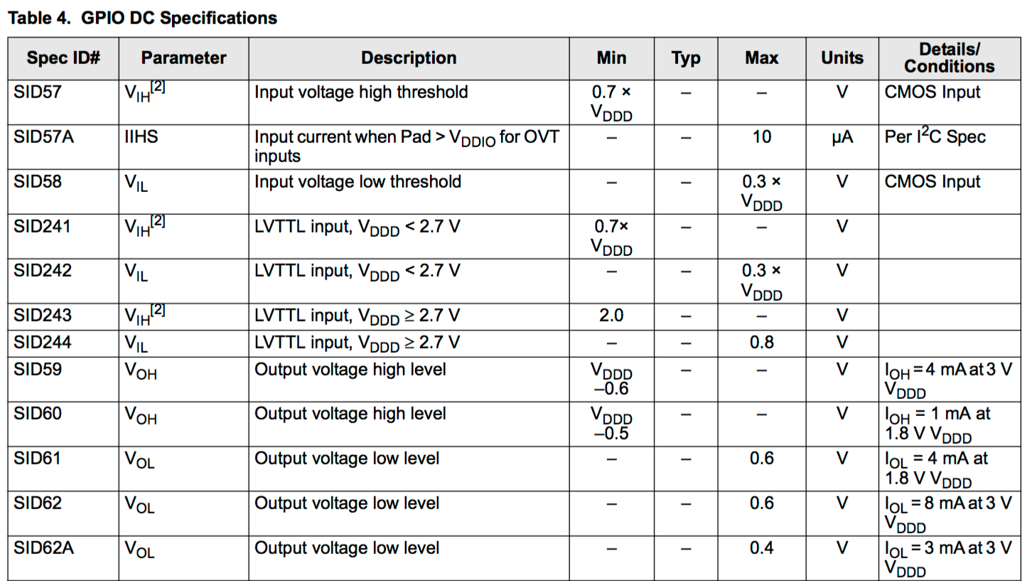
From the PSoC Datasheet I find that the maximum current in any GPIO is 25mA. That means the maximum current through any of LED/Resistor branches must by less than one fourth (because I have 4 paths) of 25mA = 6.25mA. We know that the forward voltage of the LED is about 3V. In the previous post about LEDs I showed you that the worst case HighOutputImpedence is 180Ohms and the worst case LowOutputImpedence is 50Ohms. Given those numbers, what is the value of the current limiting resistors?
R1 = (5.5v – 3v – (180 Ohm*6.25mA) – (50Ohm * 6.25mA) ) / 6.25mA = 170 Ohms
Problem 2: Select One Row at a Time
How do you enable all of the LEDs to be turned on and still only select one row at a time? The answer is that you need to time division multiplex the rows.
- Turn on row 0 for 10ms, turn on the correct columns
- Turn on row 1 for 10ms, turn on the correct columns
- Turn on row 2 for 10ms, turn on the correct columns
- Turn on row 3 for 10ms, turn on the correct columns
- Go back to the start
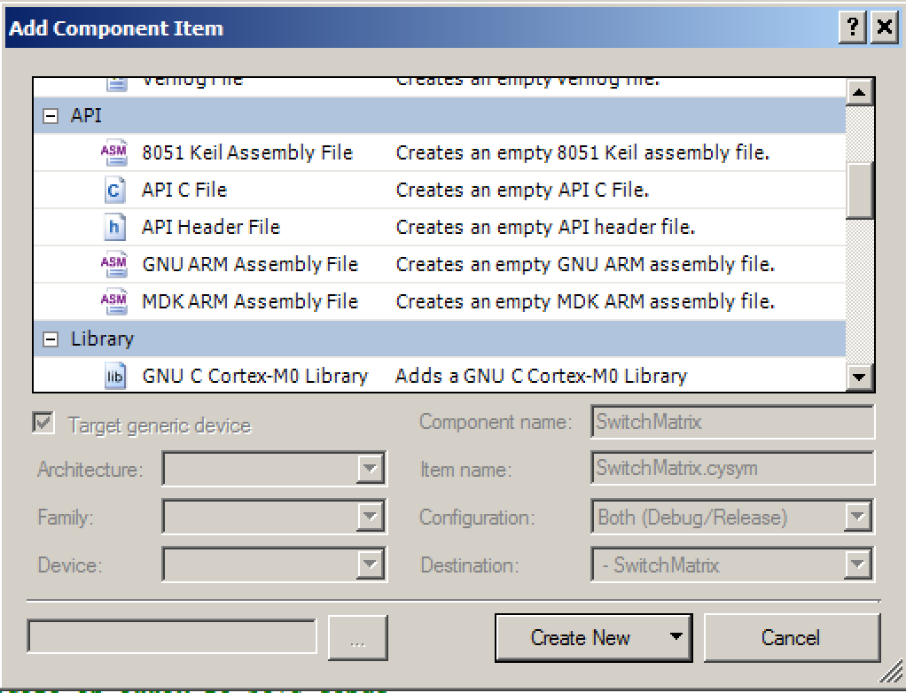
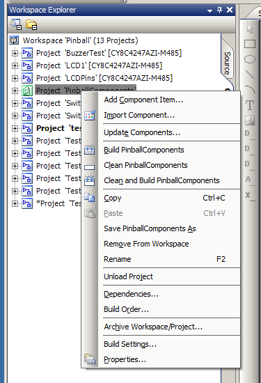
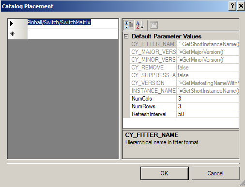
This means the LEDs will “blink” but they will blink so fast that you will not see them blinking. The LEDs are being refreshed at 25Hz with a maximum duty cycle of 25%. Before I build a general purpose component (the topic of the next post) I will make .h/.c files to implement the the timing scheme. I start this process by copying the “TestMatrix” project from the previous post into a new project called “TestLedBlinking”.
What should the API for the LED system be? What do I want the user of the component to be able to do?
- Start the system
- Turn on a specific LED
- Turn off a specific LED
- Toggle a specific LED
- Start an LED to blinking at some frequency
- Stop the blinking of a specific LED
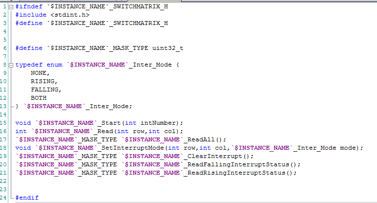
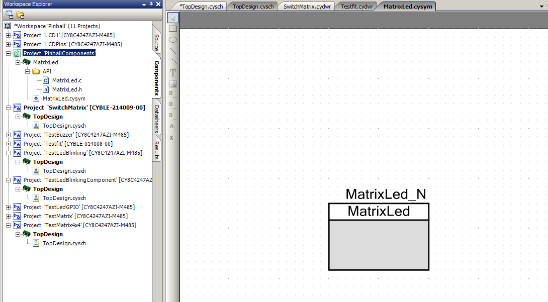
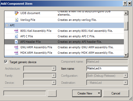
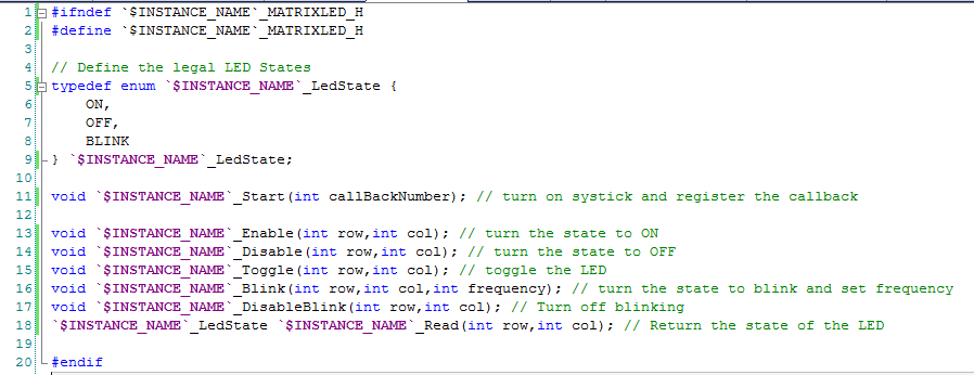
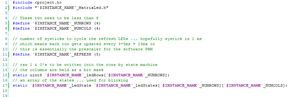
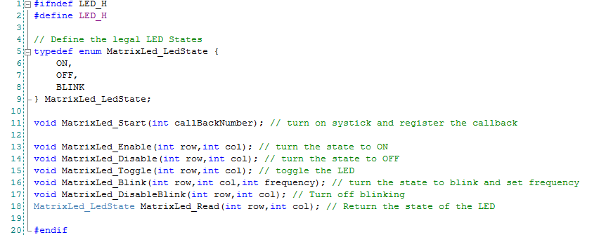
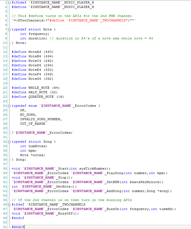
To implement this I add a “.h” file called “led.h” to my project. This file will contain the public interface to my LED system. On lines 11-18 I create the function prototypes for the interface. But what are lines 5-9 about? I want the LEDs in my system to have three possible states (ON,OFF and BLINK) but a “binary” variable is only two states. I could use an integer with some convention about what 0,1,2,3,…. means with #defines. But this is error prone as it is not type checked by the compiler. To help avoid the errors I create a new Type of variable (using enum) called “MatrixLed_LedState” that has the three states that I am interested in. The rest of the file contains the public interface to the component.
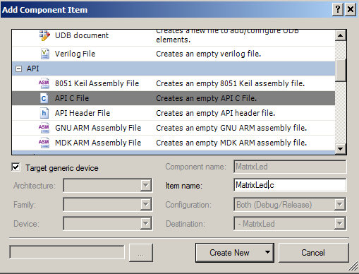
After I finish the public interface I now need to build the implementation. To do this I add “led.c” to my project with the c-functions and variables.
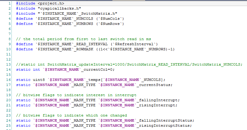
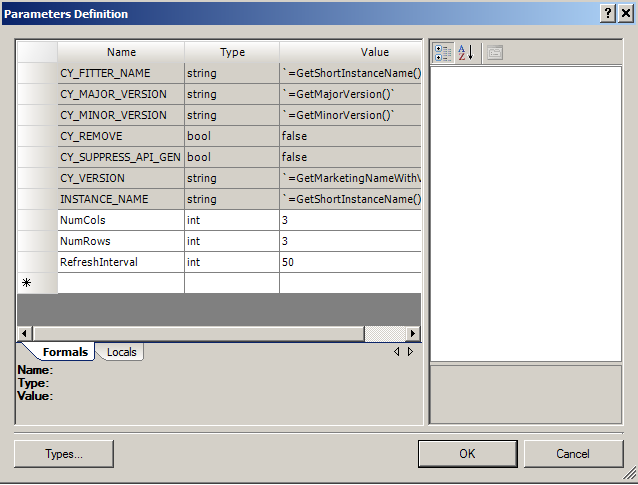
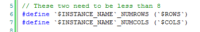
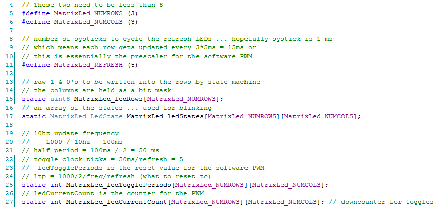
Lines 5-6 define the number of rows and columns in my design. My comment says that you need to keep this less than 8 because the PSoC can only write to one 8-bit port at a time. I use this to simplify the firmware.
Line 15 declares an array of uint8s that are the actual bits that need to be written to the columns to turn on/off the led in that row.
Line 17 declares a (row by column) sized array to keep track of the state of each LED. It is of type “MatrixLed_LedState”
Lines 19-27 declare two arrays to keep track of the “counter” and “period” of the software PWM that I use to blink the LEDs. (see the function MatrixLed_UpdateBlinking)
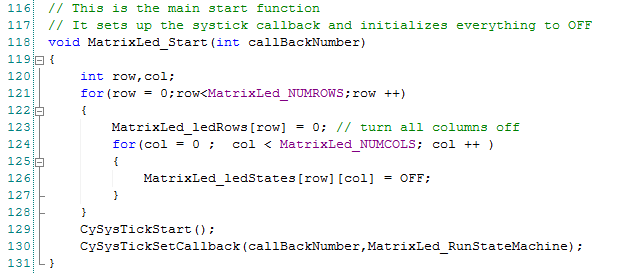
The first function to build is the “Start” function.
Lines 120-128 just iterates through all of the row,columns and sets the bit mask to 0 (LEDs OFF) and the States to (OFF).
On lines 129+130 I start the SysTick timer. I do not like using CyDelay to keep time. When you use a CyDelay the processor does what is called a busy wait loop that looks like this:
for(int i=0;i<10000;i++); // 10000 is the number of times the CPU has to go through the loop for some amount of delay. This is dependent on the CPU frequency
This “for” loop keeps the processor sitting in the same spot doing nothing but making heat. This is not going to work in our system as we need other things to be going on simultaneously (like running switches, buzzers etc). Instead of a busy wait loop I will use the built in timer in the ARM Cortex M0 core. That timer is called “SysTick”. In the Cypress PSoCs, this timer works when the CPU is Active or in Sleep. By default, it “ticks” every millisecond. Cypress provides you an API to turn on the timer called “CySysTickStart()” How do you use it? You register a callback function using the “CySysTickCallback()” This function takes two arguments
- The callback number (you can have up to 4 callbacks)
- A function pointer to the function you want called back when the timer “ticks”
The function MatrixLed_RunStateMachine is called by the SysTick interrupt. This function is the basis of the whole system. I want to every few milliseconds not every millisecond. Specifically “every few” means every “MatrixLed_REFRESH” milliseconds. I do this to save on CPU time. In order to implement this idea I keep track of number of times the interrupt has been called using the static variable on line 108. On line 112, when I reach an even number of “MatrixLed_REFRESH” I allow my processing routines to run.
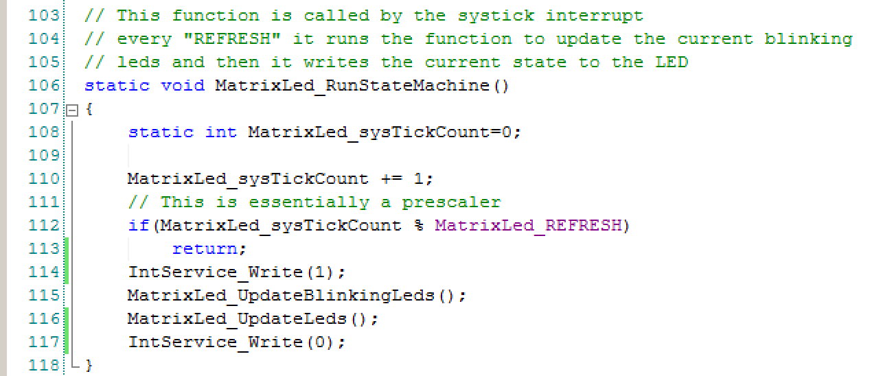
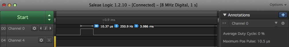
The other thing that I do in this function is toggle a pin high when I start the processing and then toggle it low when I finish. I wanted to know how long the interrupt routine ran. It is a very bad idea for interrupts to take a long time as it can impact other things going on in the system e.g. servicing the BLE. By toggling the pin I can attach the test board to a logic analyzer and see how long the interrupt service routine takes. Here is a screen shot from my Salea Logic Analyzer where you can see that the interrupt takes 10.5uS (worst case) runs every 3.986 ms which works out to a duty cycle less than 1% (so it shows 0%). Why is it 4ms as earlier I said that you should do 10ms? I tried 10ms, but I can see the LEDs flickering so I increased the update frequency.
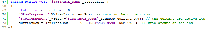
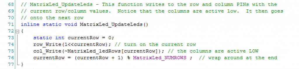
The next block of code drives the column and row pins to the right values. On line 73 I declare a static variable currentRow which I use track which row needs to be driven this time. Remember this function gets called every 10ms by the SysTick Interrupt. Line 74 actually turns on the current row. It uses the “<<” which is the c-operator also known as left shift. That makes a value with a “1” in the position of the current row and a “0” in the other bits. On line 75 I set the column bits to the correct value. The system is “active low”, meaning you activate a column by driving it to ground. After all of the updates are done you setup for the next time on line 76 by moving to the next row.
The only other interesting thing about this function is that I declared it with the keyword inline. This keyword tells the compiler to NOT call it as a function but to put it directly in the assembly language at the place where it is called i.e. to embed it there. Using inline will save CPU cycles as you don’t have to save a bunch of registers onto the stack, jump, pull a bunch of registers and jump back. The only downside is that you will get multiple copies of the same function (wasting space).
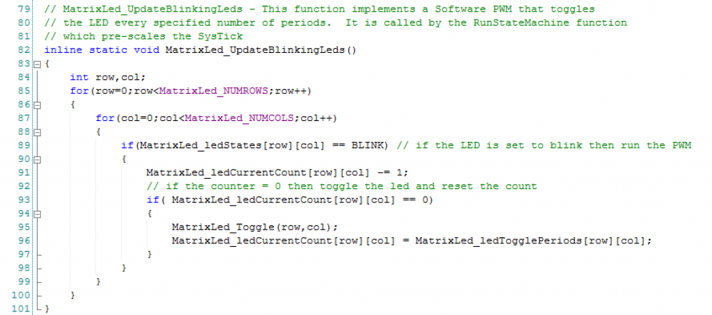
The next function handles the blinking. The blinking is a simple software PWM. The PWM counts from the “Period” down to 0. When it hits 0, it toggles the LED, then resets the counter back to the Period.
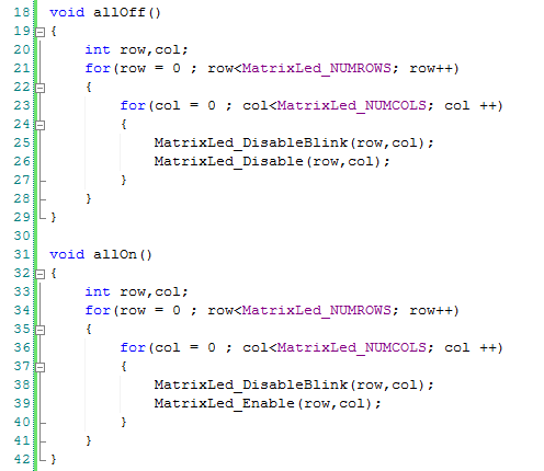
This function when called, iterates through the matrix of LEDs (using the two nested for-loops), if an LED is in the blinking state (line 89) then do the down count and toggle the LED if needed.
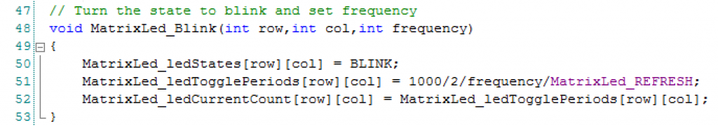
The MatrixLed_Blink function configures the state and period. The period is set by:
Period = 1000/frequency/2/MatrixLed_REFRESH
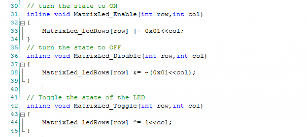
The last three functions are just helper functions to set the bits in the “MatrixLed_ledRows” for the column values.
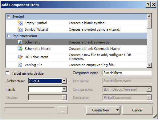
In the next post Ill show you how to turn all of this into a component.
You can find all of the source code and files at the IOTEXPERT site on github.
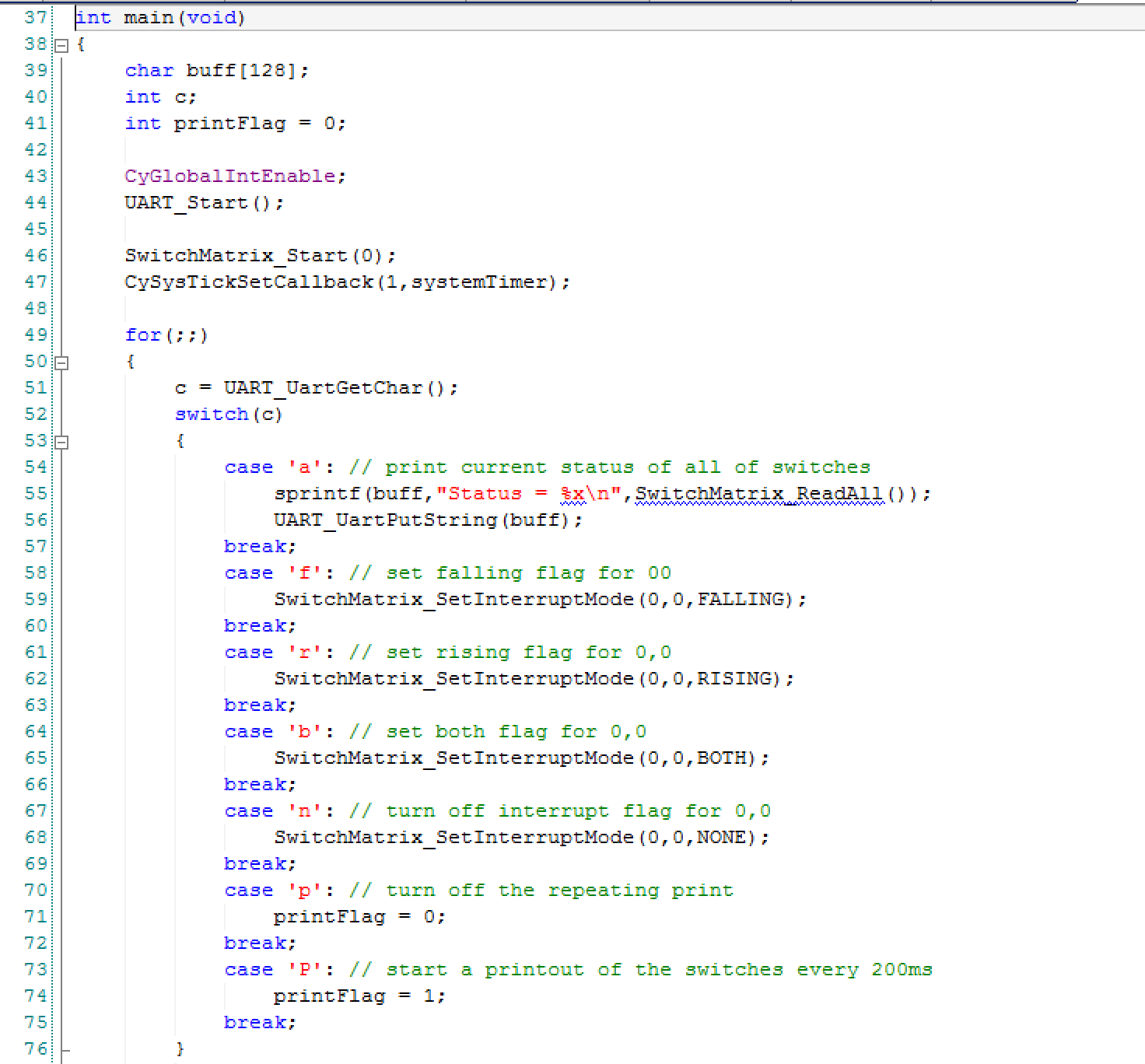
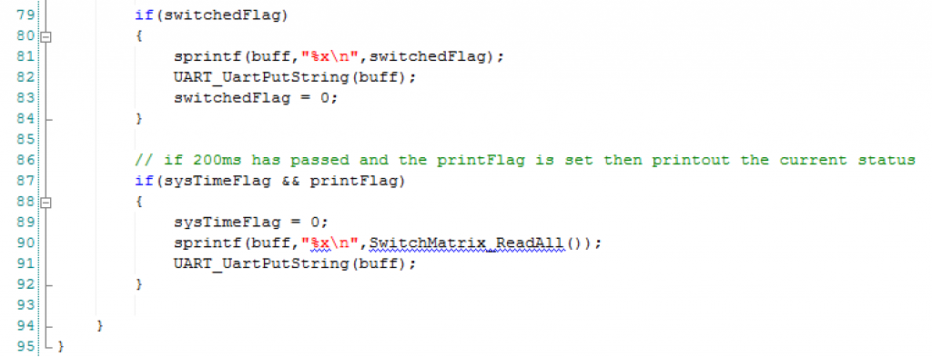
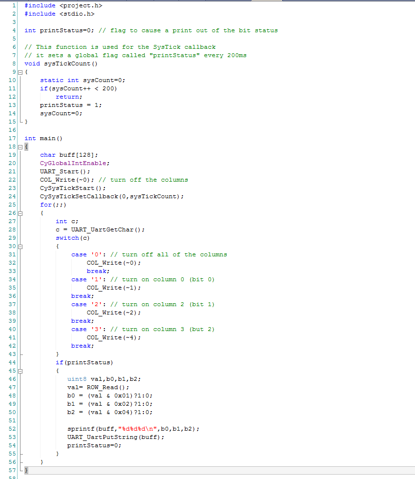
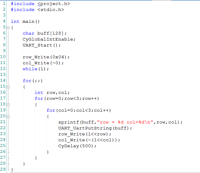
 In the main program I first start all of the components, interrupts etc in lines 43-47. On lines 52-75 I process the user input and try out different functions of the component.