Summary
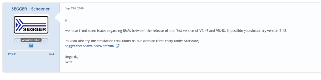
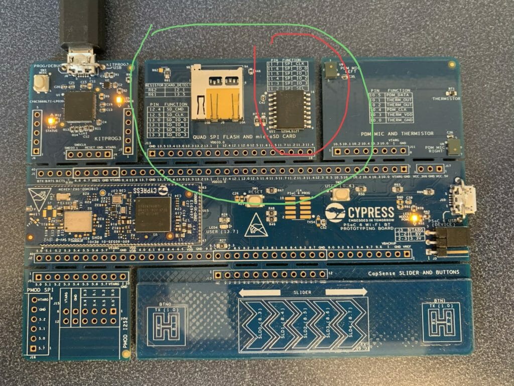
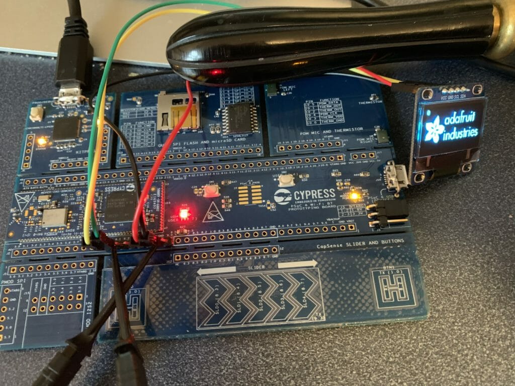
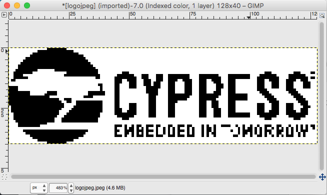
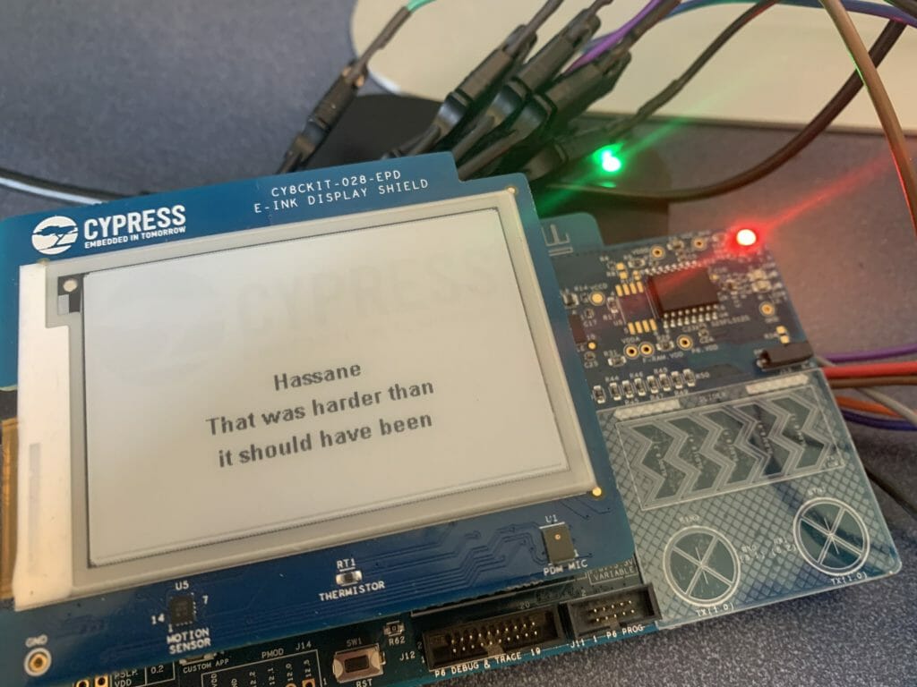
One of my very influential readers is working on a project where he wants to use the CY8CKIT-028-EPD. But, he wants to use Modus Toolbox 1.1 instead of PSoC Creator and he observed, correctly, that Cypress doesn’t have a MTB code example project for the CY8CKIT-028-EPD. I knew that we had a working code example in PSoC Creator (CE223727), so I decided to do a port to MTB1.1. This turned out to be a bit of an adventure which required me to dig out a logic analyzer to solve self inflicted problems. Here is a picture I took while sorting it out.
There are a few things in the PSoC Creator example code which I didn’t really like, so, for the final solution, I would like it to be
- In Modus Toolbox 1.1
- Using FreeRTOS
- Using the Segger emWin graphics library
- Getting the best response time
- Using DMA to drive the display
For this article I will go through these steps:
- Build CE223727 EmWin_Eink_Display in PSoC Creator
- Explain the PSoC Creator Project
- Create a new MTB Project & add the FreeRTOS, Segger emWin and stdio middleware
- Configure the device for the correct pins, clocks and peripherals
- Setup FreeRTOS and Standard I/O
- Copy the driver files into the MTB project from the PSoC Creator workspace
- Port the drivers and eInkTask to work in MTB
- Program and Test
- (Part 2) Update the driver to remove the hardware timer
- (Part 2) Update the example to remove polled switch and use a semaphore
- (Part 2) Update the driver to use DMA
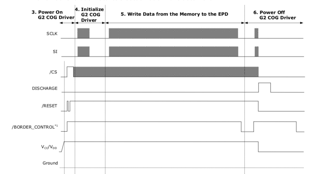
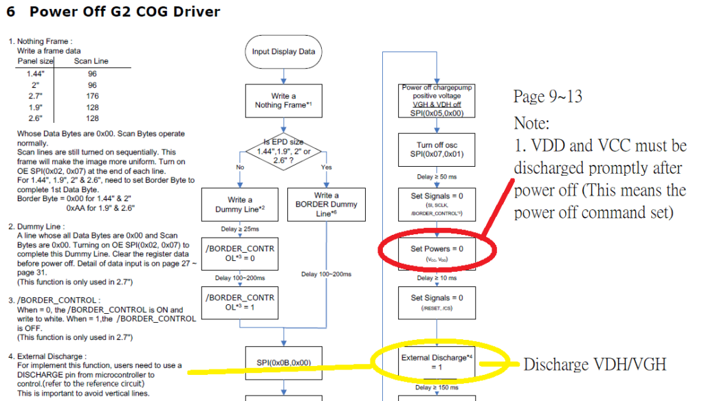
- (Part 2) Explain how the EINK EPD Display Works
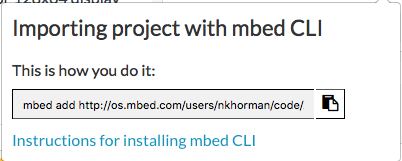
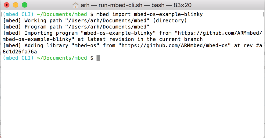
If you lack patience and you just want a working project, you can download it from the IoT Expert GitHub site. git@github.com:iotexpert/eink-emwin-mtb1-1.git
First build CE223727 EmWin_Eink_Display in PSoC Creator
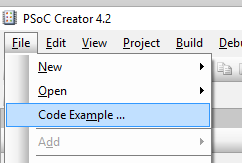
Start by finding the code example project for the Eink Display. In PSoC Creator on the File->Code Example menu you will be able to pick out the code example.
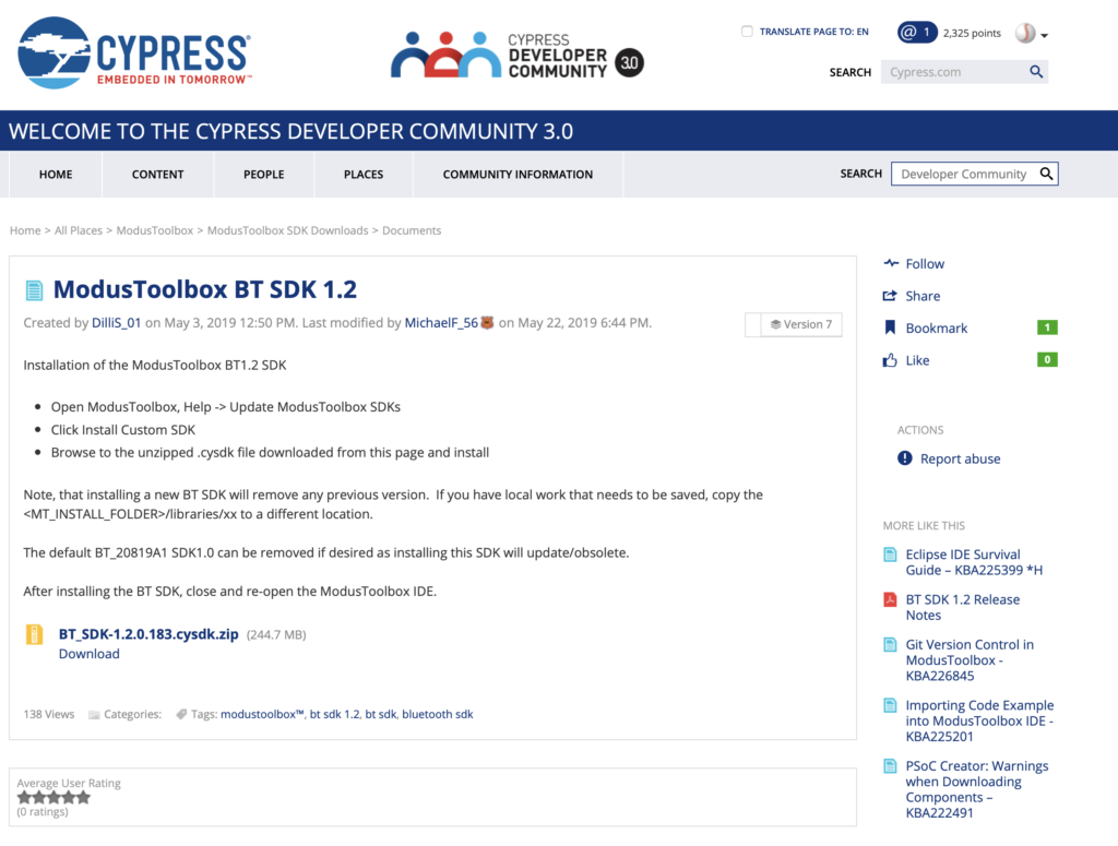
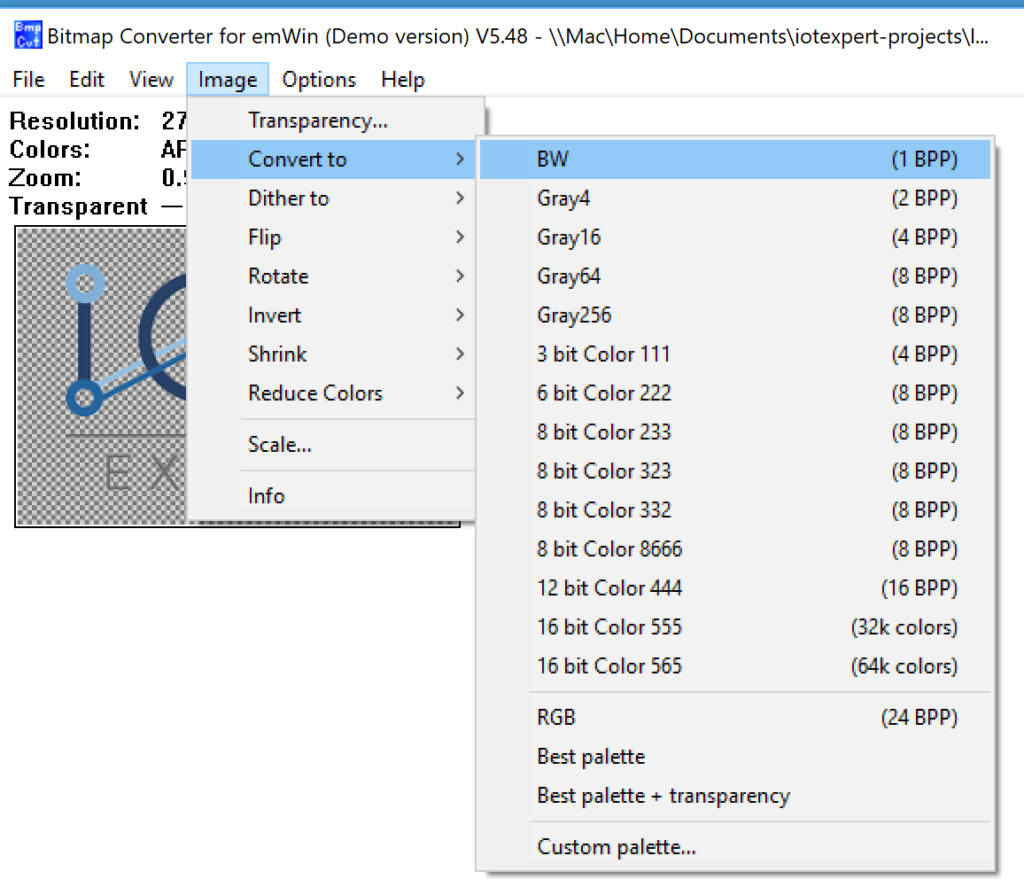
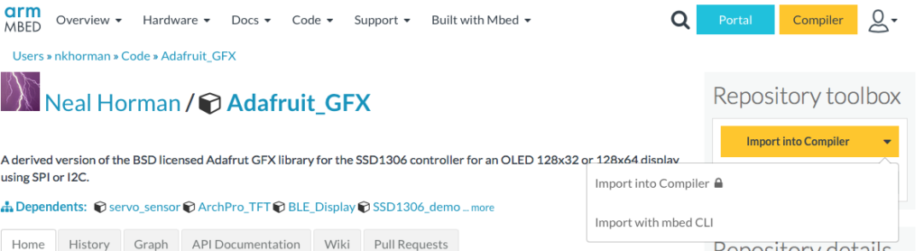
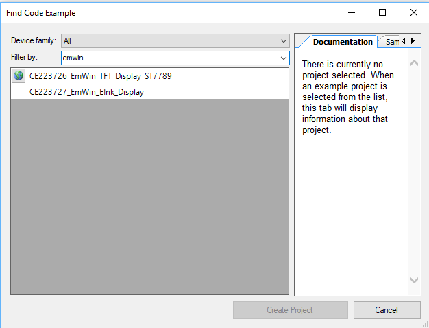
There are a bunch of code examples, so the easiest way to find them is the filter based on “emwin”. I did this because I knew we had used the Segger emWin Graphics library. Notice in the picture below there are two emWin examples. One with a “world” beside it and one without. The world symbol means that it is on the internet and you will need to download it. You can do that by clicking the world button. Probably, you will find that your CE223727 EmWin_EInk_Display will have a world beside it and you will need to download it before you can make the project.
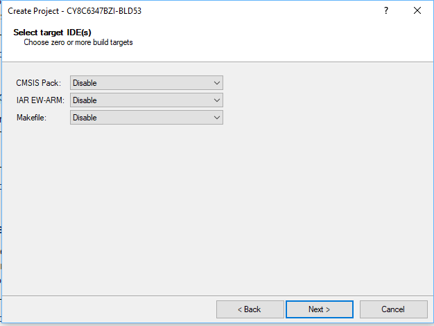
Once you click create project it will ask you about the project. Just click “next”
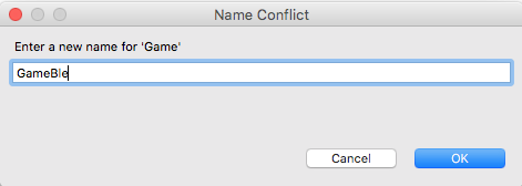
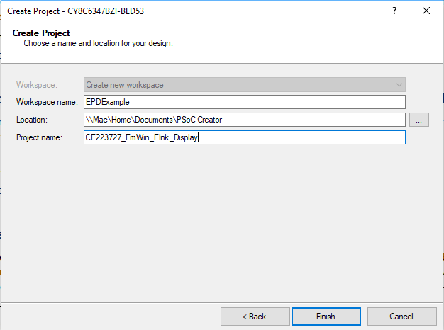
Then give your project (and workspace) a name. I called the workspace “EPDExample” and the project “CE22….”
After all of that is done you will have a schematic (and all of the other stuff required for the project).
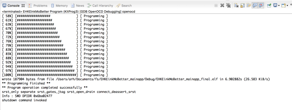
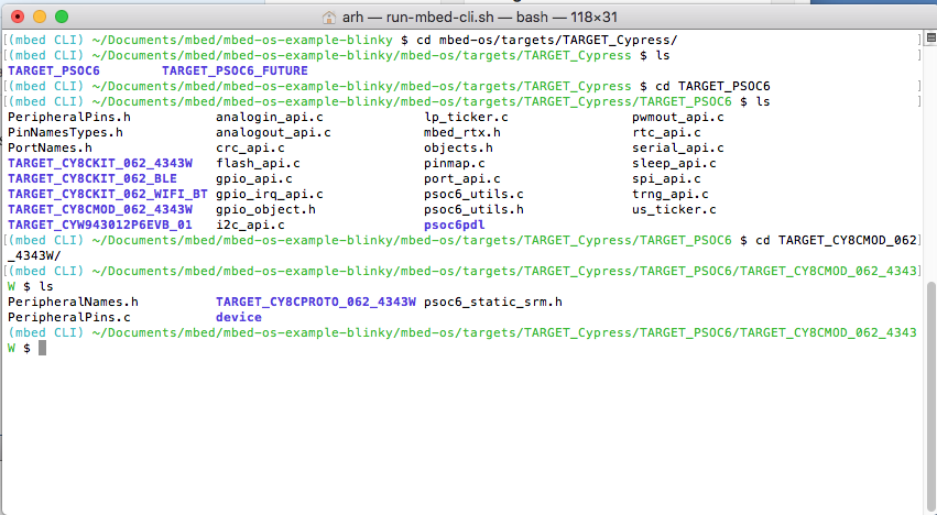
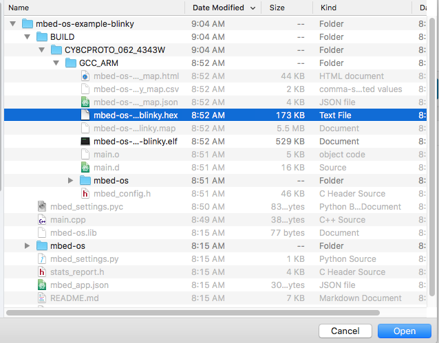
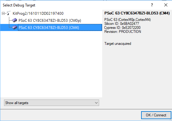
When you click the program button it will ask you which MCU target to program (pick either, it doesnt matter)
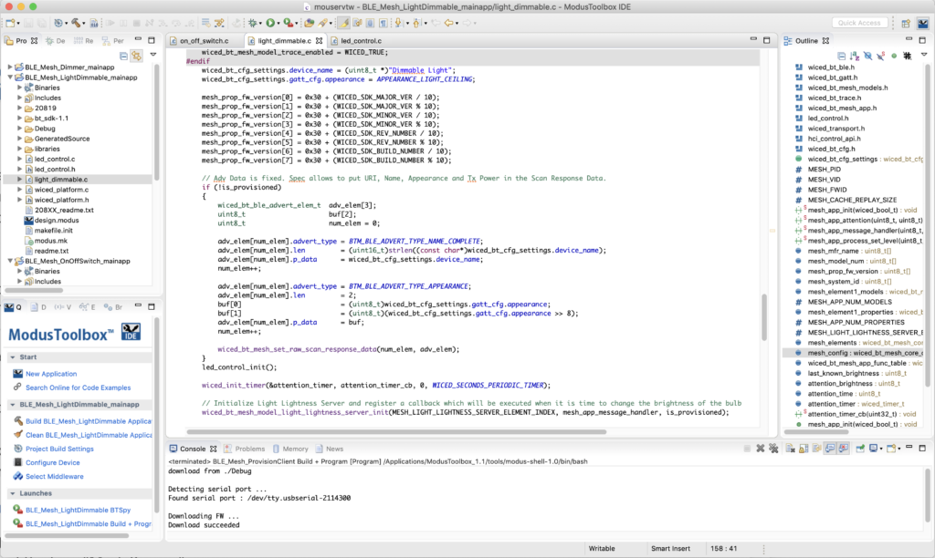
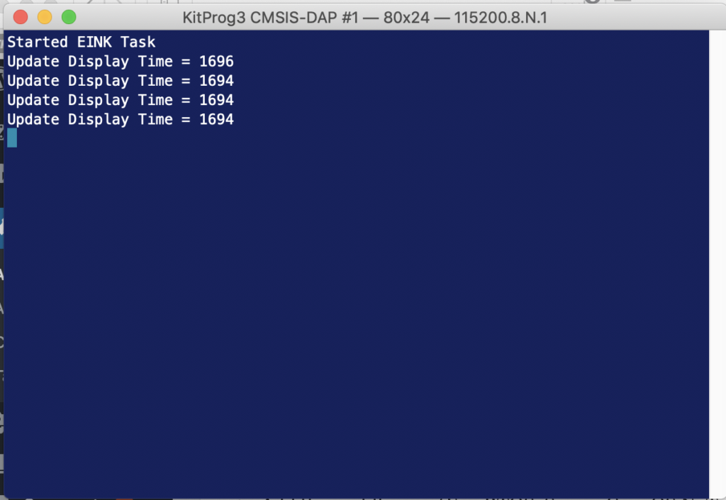
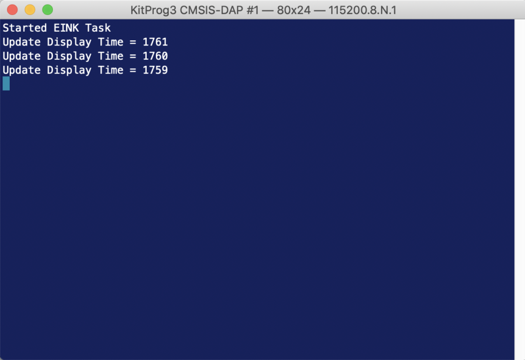
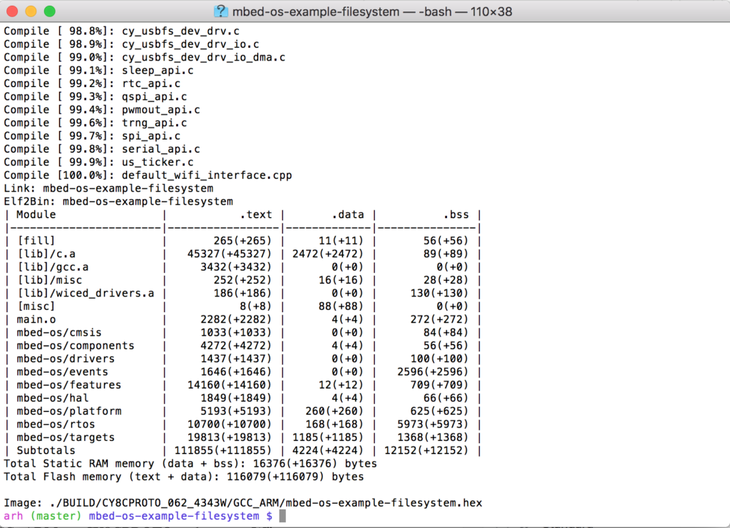
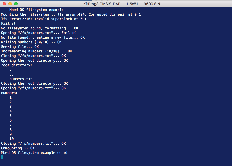
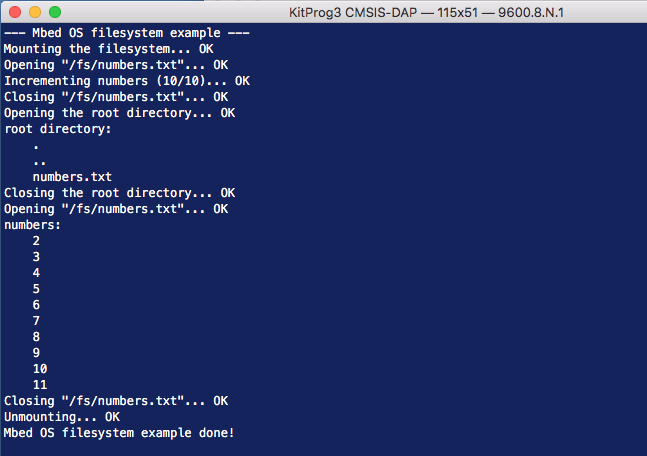
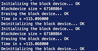
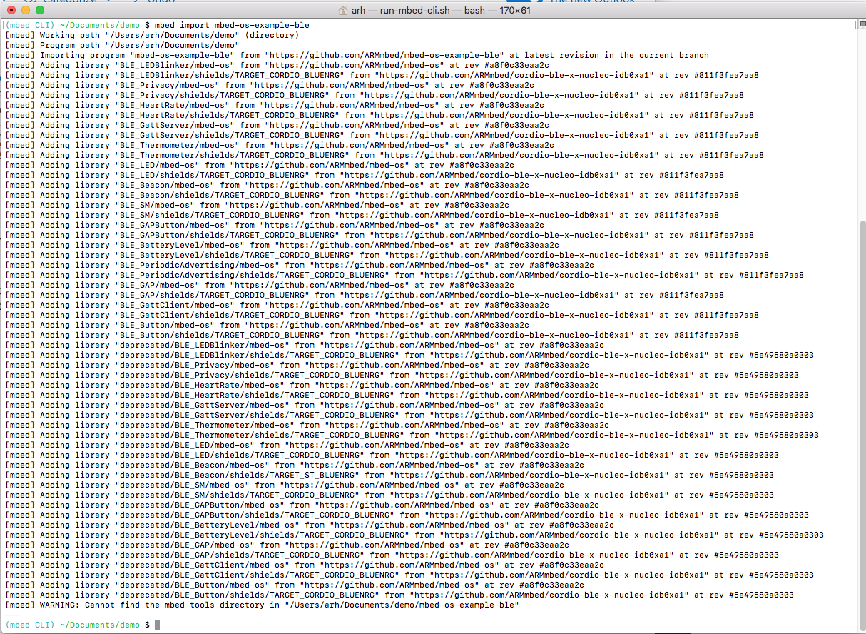
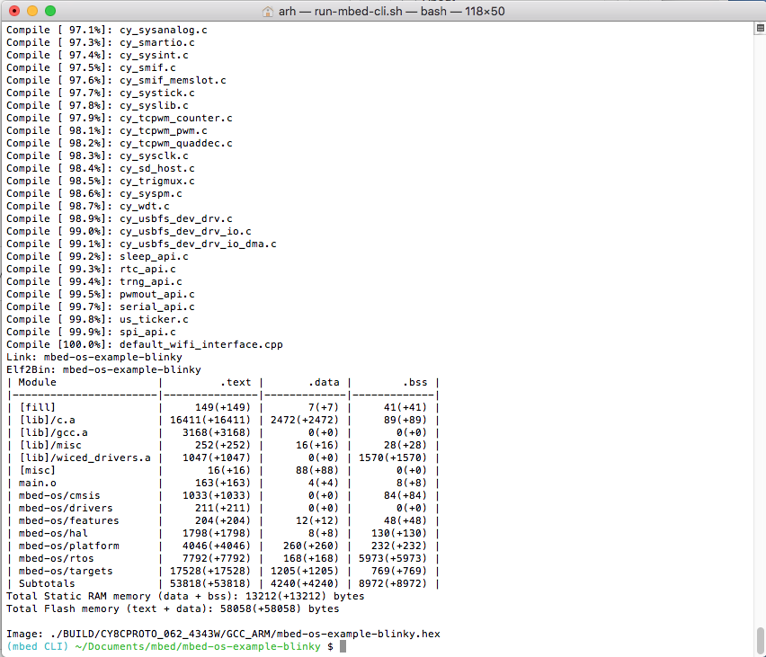
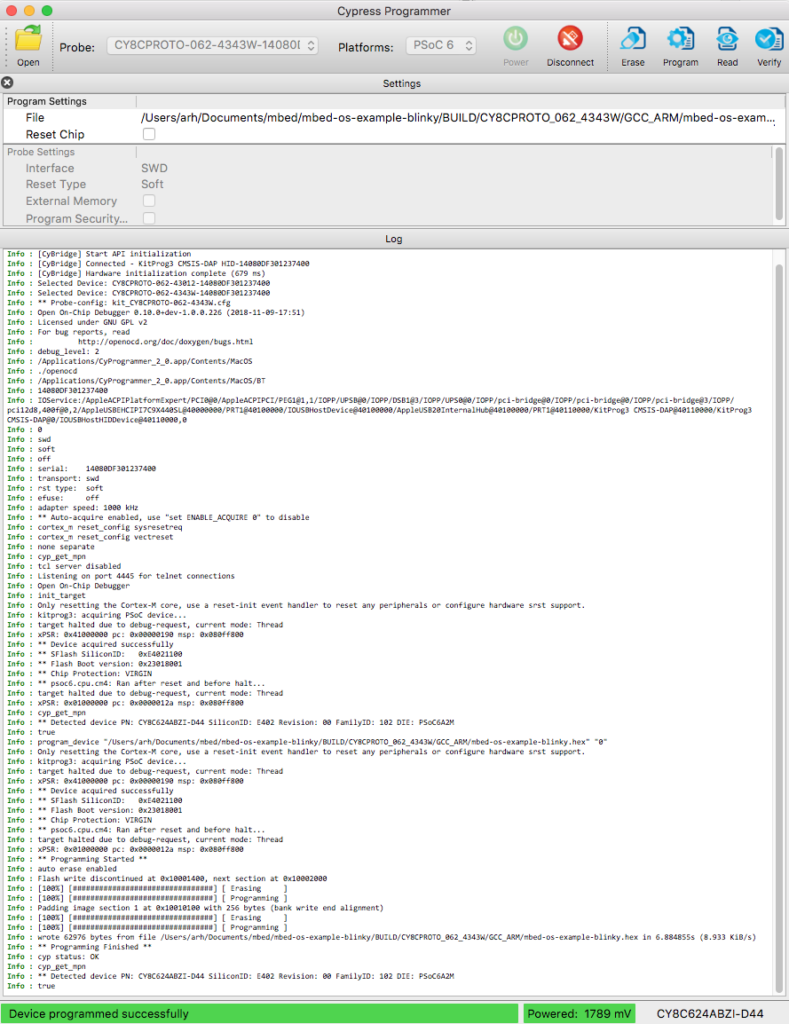
After a while, your console window should look like this.
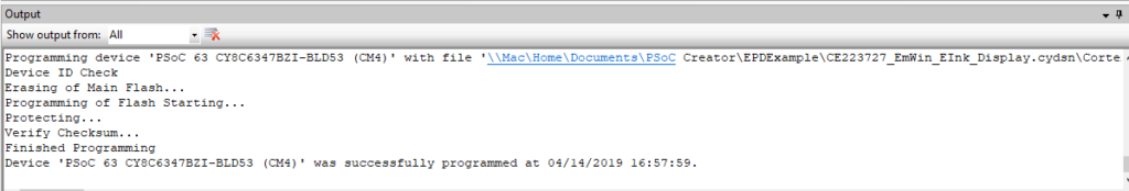
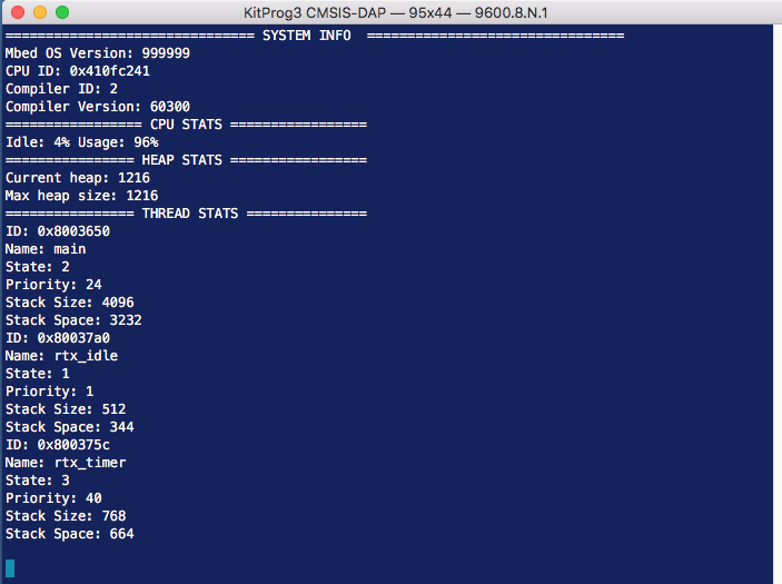
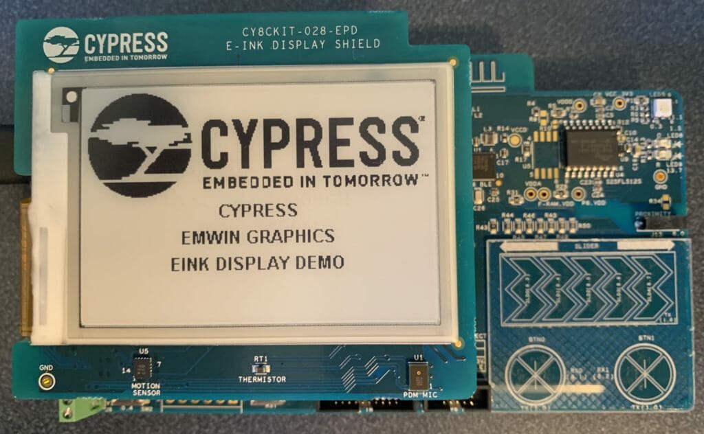
And you development kit should do its thing.
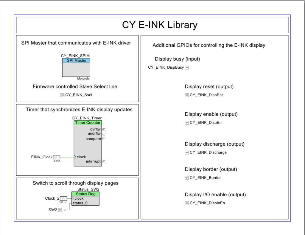
Explain the PSoC Creator Project
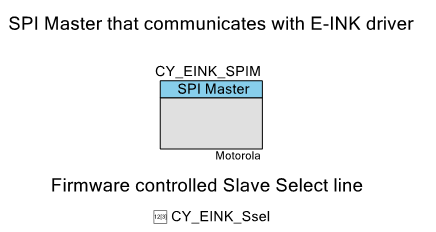
Now, lets have a look at the project. Starting on the upper left hand part of the schematic you find that the interface to the EPD is via a SPI. The SPI slave select is controlled with the Pervasive driver firmware rather than letting the SPI block directly control it.
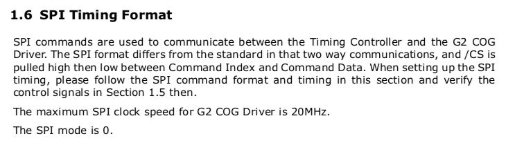
The SPI is configured to be 16 megabits per second with CPHA=0 and CPOL=0.
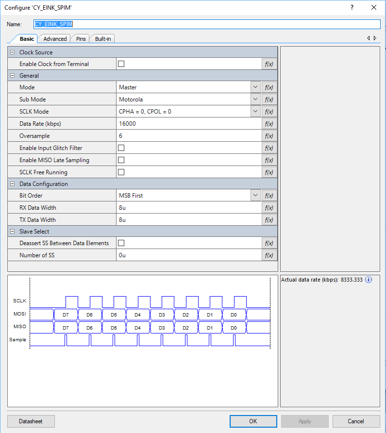
I didn’t notice this at first, but in the picture above you can see that the actual speed of the SPI is 8.33 mbs. That isn’t 16mbs for sure. But why the gap? The first thing to know is that in order for the SPI block to work correctly the input clock must be set at the desired datarate times the oversample. What is oversample? That is a scheme to get rid of glitchy-ness in the input signal. In this case it will take 6 input samples to determine if the input is a 1 or a 0. (median filter I think). With this configuration the input clock to the SCB needs to be 16mbs * 6 = 96mhz.
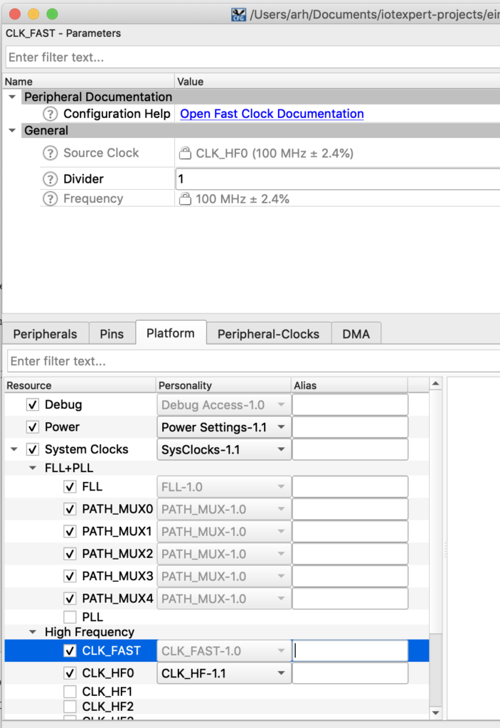
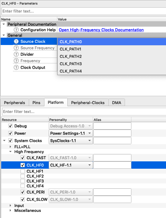
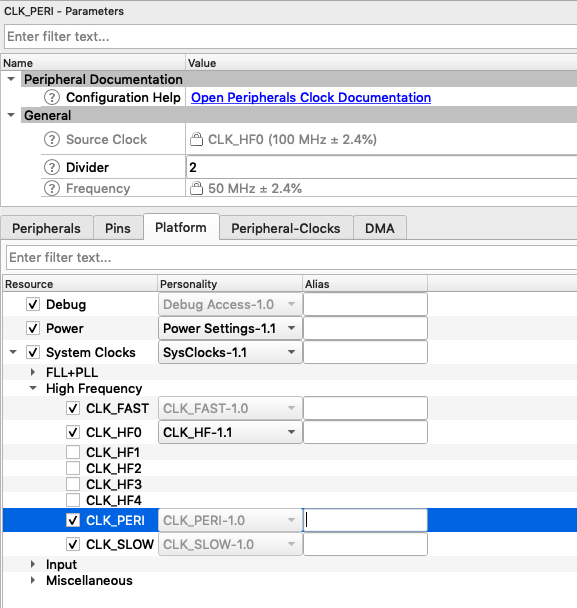
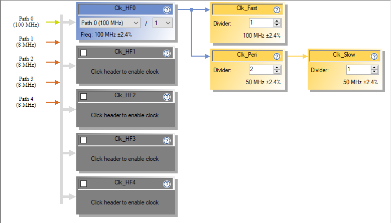
But what is the input clock frequency? If you click on the dwr->clocks you will see this screen which shows that the input clock is 50Mhz (the last line highlighted in blue). Further more you can see that the source clock for the SCB is “Clk_Peri”. When you divide 50mhz source clock rate by 6 oversample you will find that the actual bitrate is 8.33kbs.
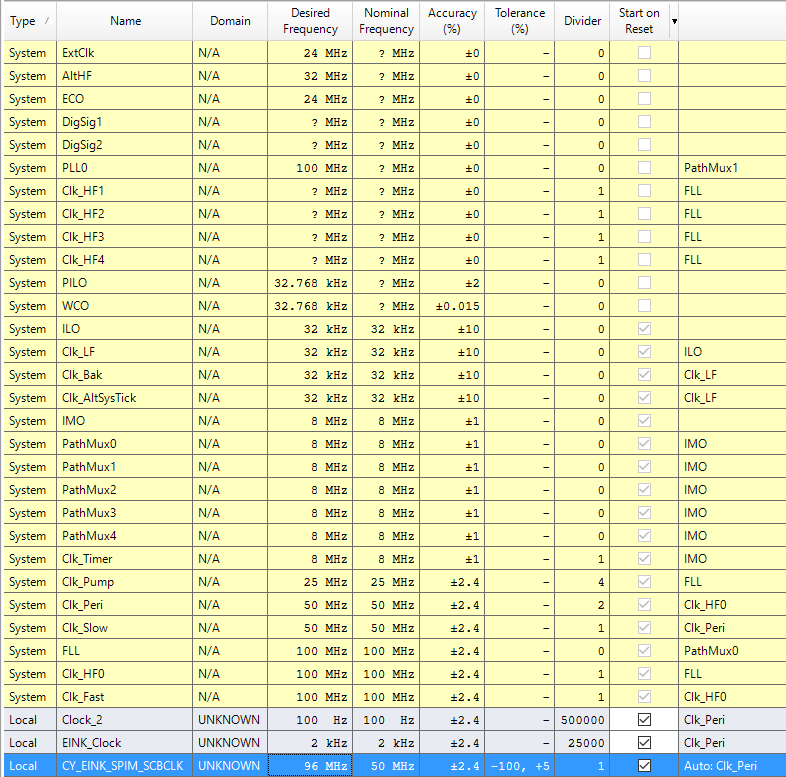
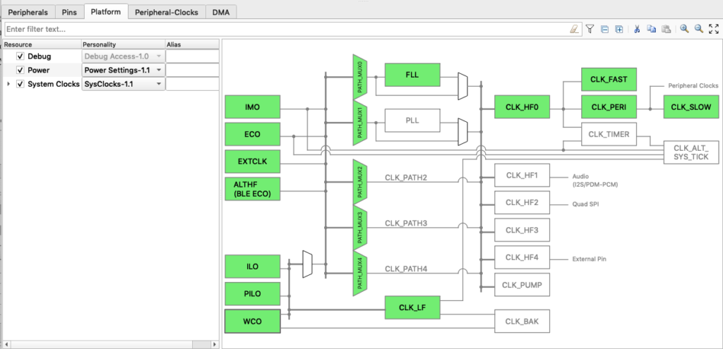
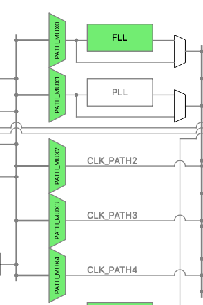
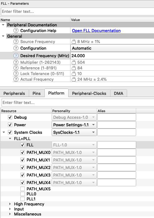
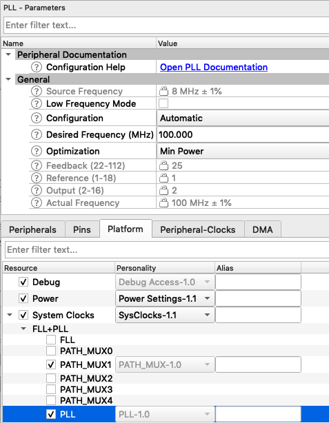
But where does the 50mhz come from? Well, the clock system is driven by the “IMO”. IMO stands for internal main oscillator and it is a trimmed RC oscillator built into the chip. (thanks Tim). This oscillator runs into an FLL which up converts it to 100MHz.
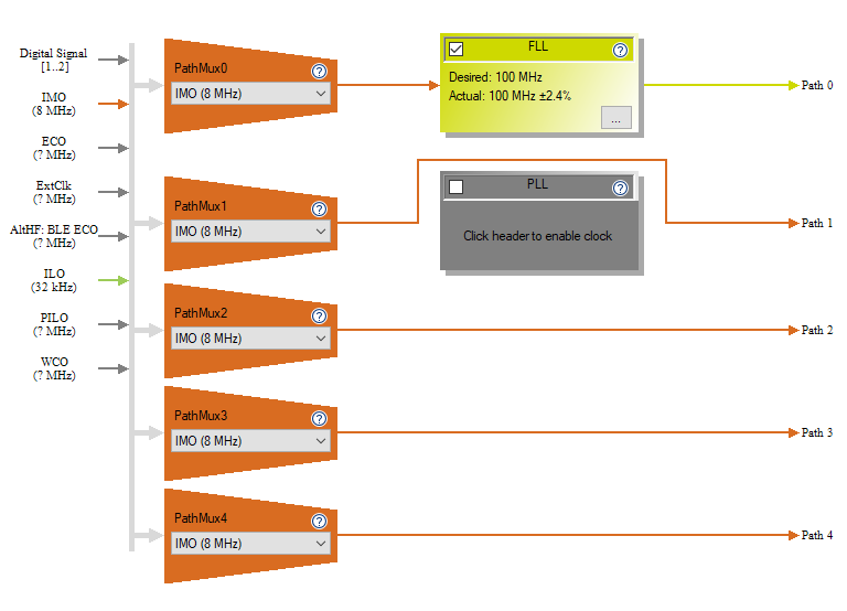
That signal is then run into the “Clk_Peri” divider which divides it by two to yield a clock of 50MHz. Which is not all that close to 96MHz… and means that our SPI runs at the wrong speed.
But what does the EPD driver chip actually want? You can find the documentation for this EPD on the Pervasive website. That web page also has a link to the Product Specification 2.7″ TFT EPD Panel (E2271CS021) Rev.01 as well as the driver chip COG Driver Interface Timing for small size G2 V231
When you look in the timing document you will find that the actual chip can take up to a 20Mhz input clock. This means that our code example actually updates the screen at 42% (8.33/20) of what it could. That gives us a chance to make things faster… which I will do after the port to MTB.
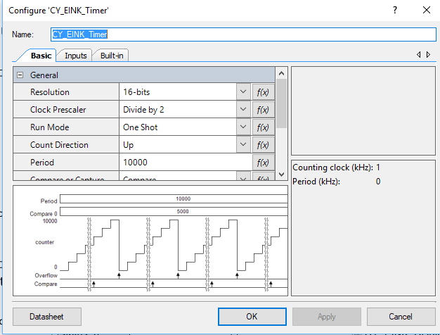
The next sectin of the schematic has a TCPWM that is configured as a timer. This has an input clock of 2kHz.
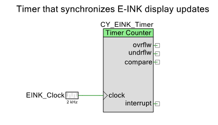
And is setup to divide by 2 which will yield a counter that updates every 1ms. The author of this code example used the TCPWM to time operations inside of the driver (which I will also replace with something better)
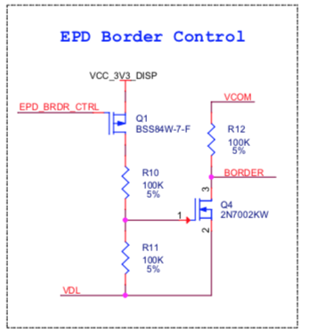
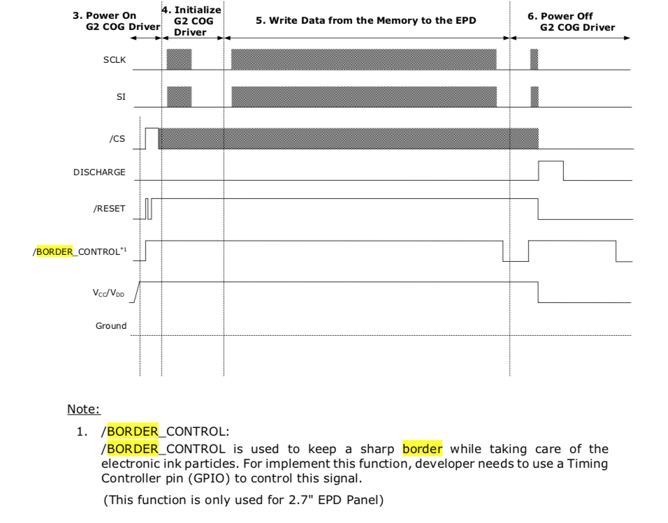
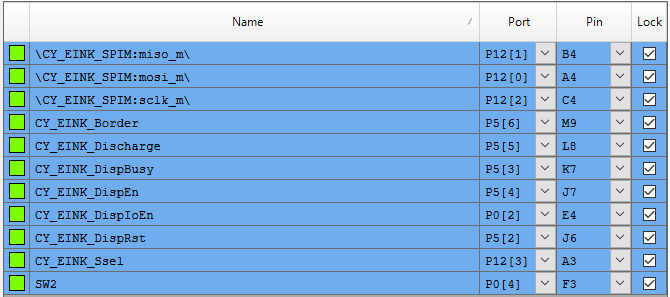
Lastly there are some GPIOs that control various control pins on the display. I don’t really know what all of the pins do, but will sort it out in the next article.
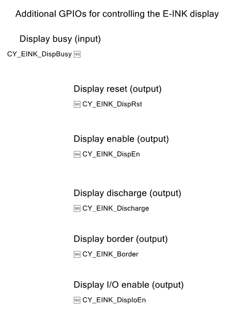
And all of the pins are assigned like this:
Create a new MTB project & Add the Middleware
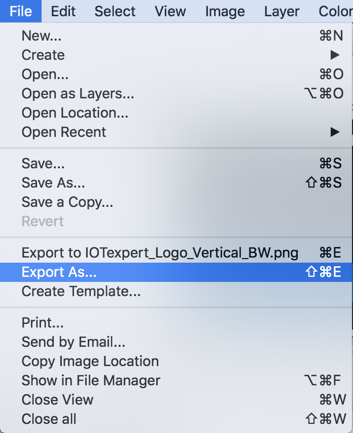
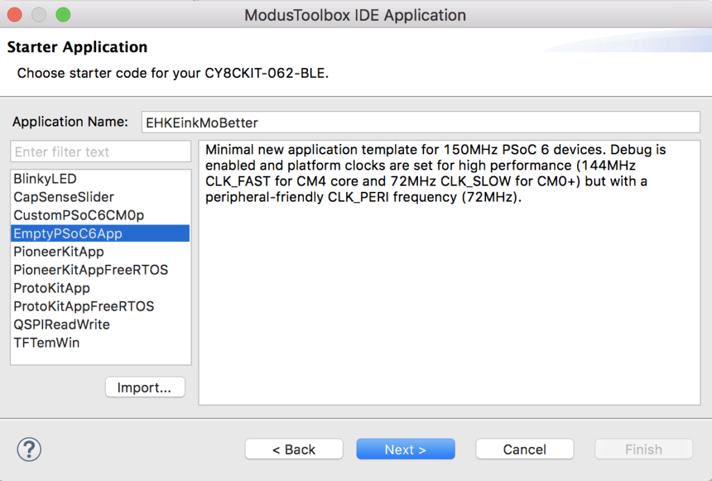
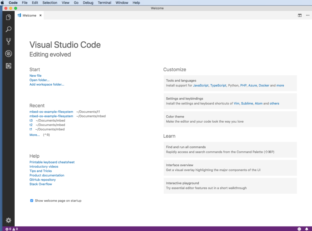
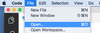
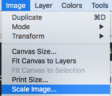
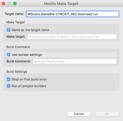
It is time to start the project in MTB. Start up Modus Toolbox 1.1 and select File->New->ModusToobox IDE Application 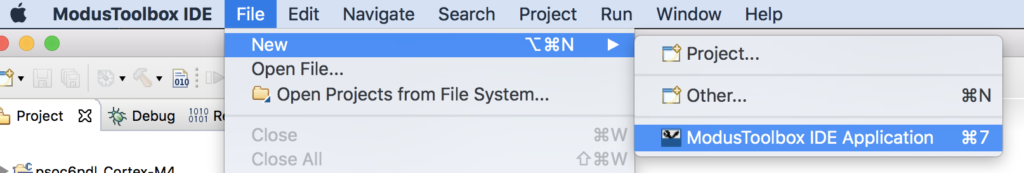
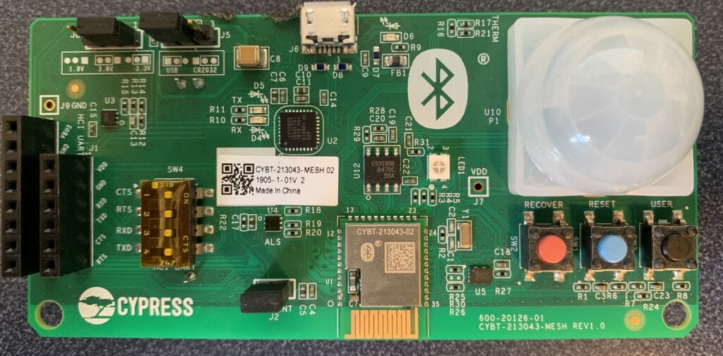
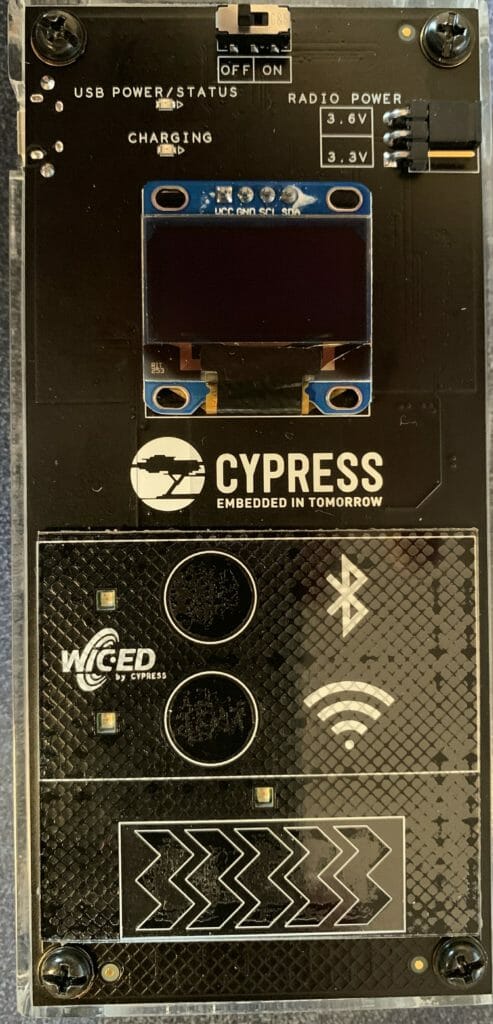
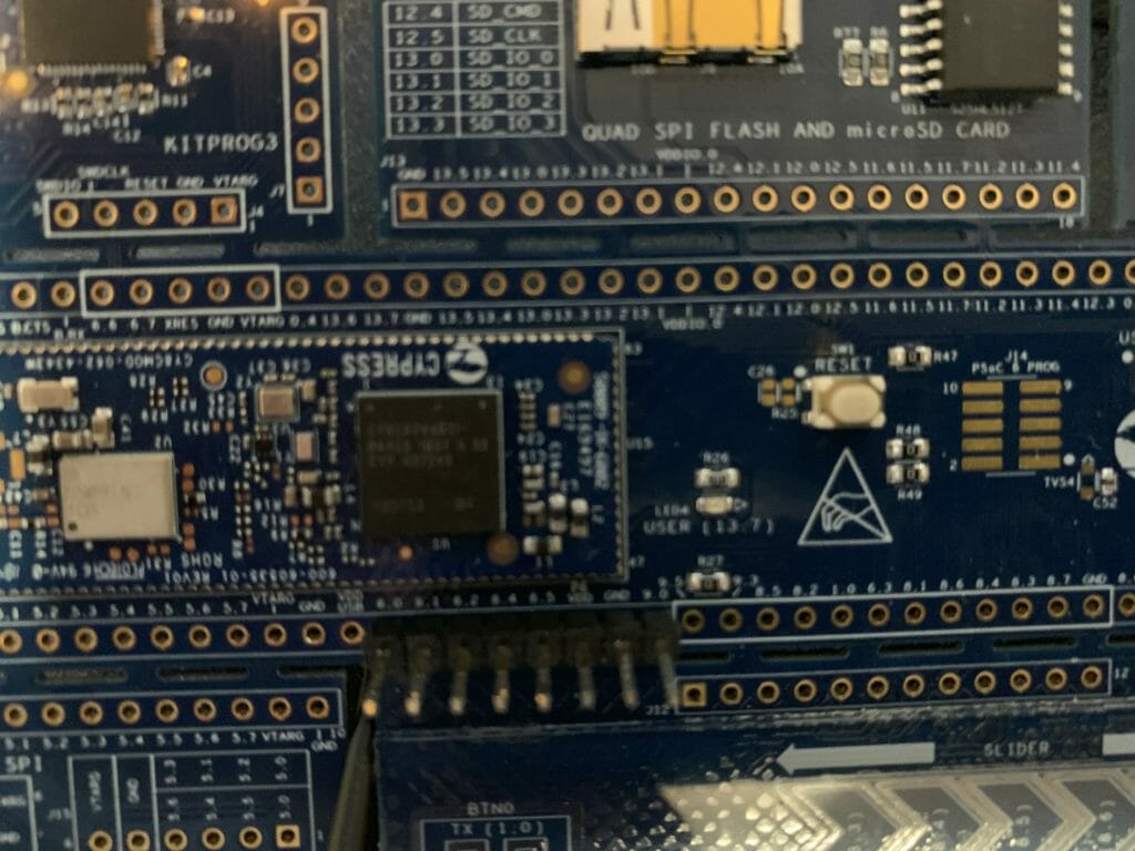
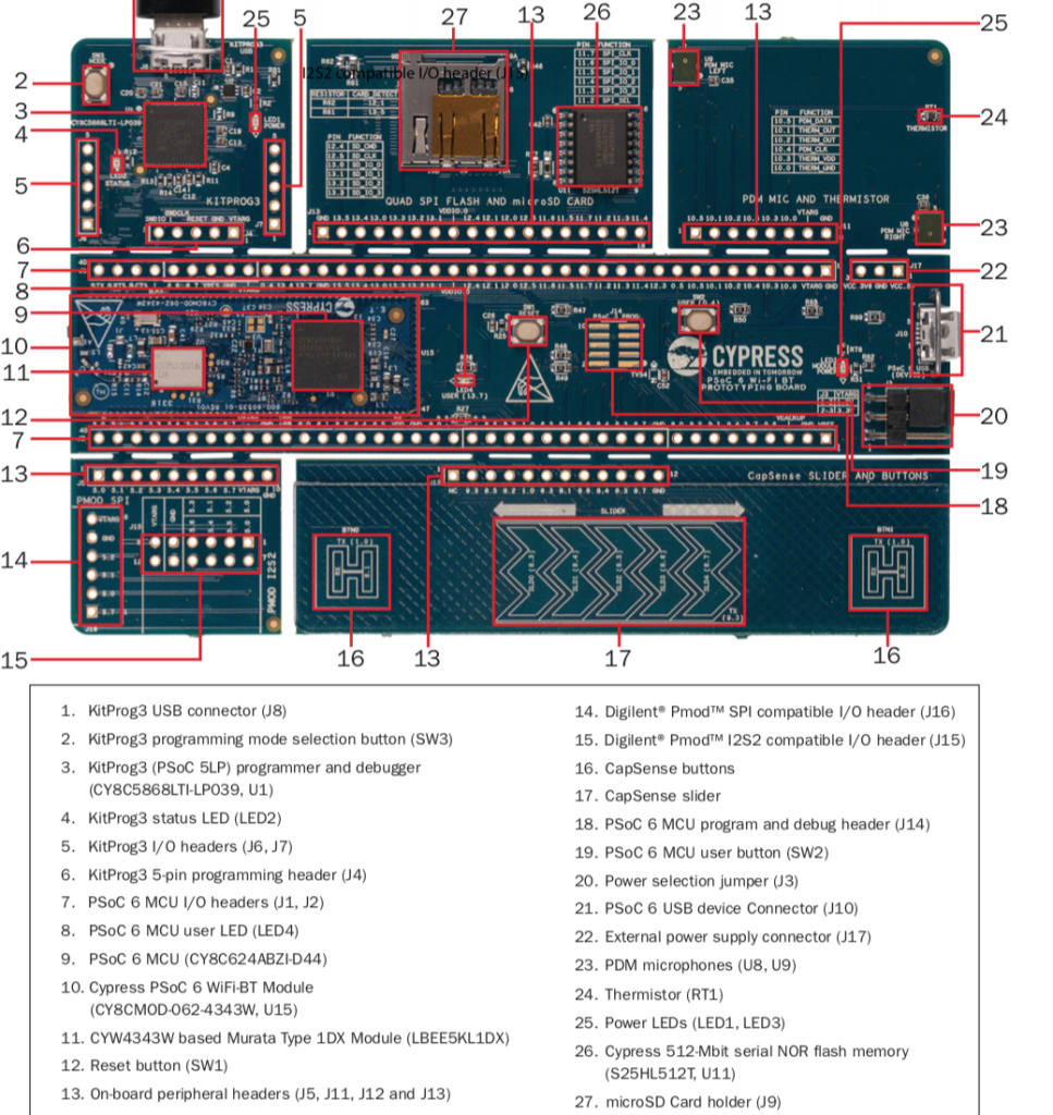
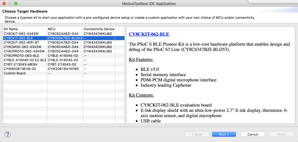
Then select the CY8CKIT-062-BLE Development Kit. This kit comes with the CY8CKIT-028-EPD EINK Shield that you can see in the pictures above.
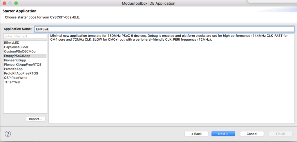
I decide to call my project “EHKEink” and I derive my project from the “EmptyPSoC6App” template.
Once that is done, Let it rip.

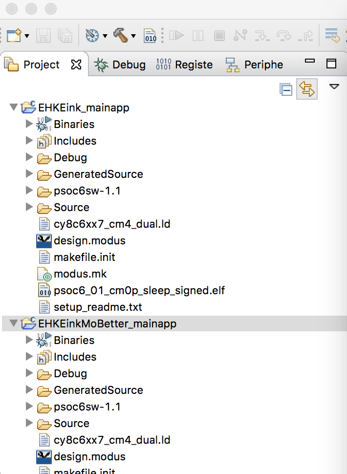
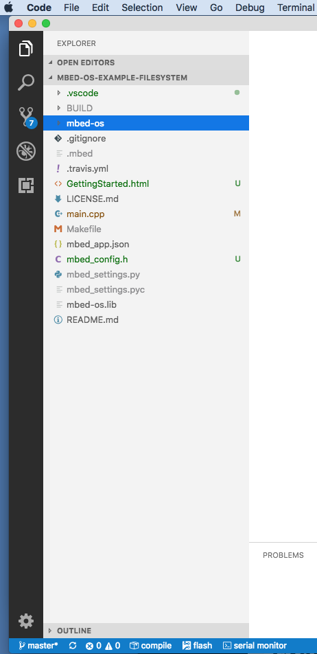
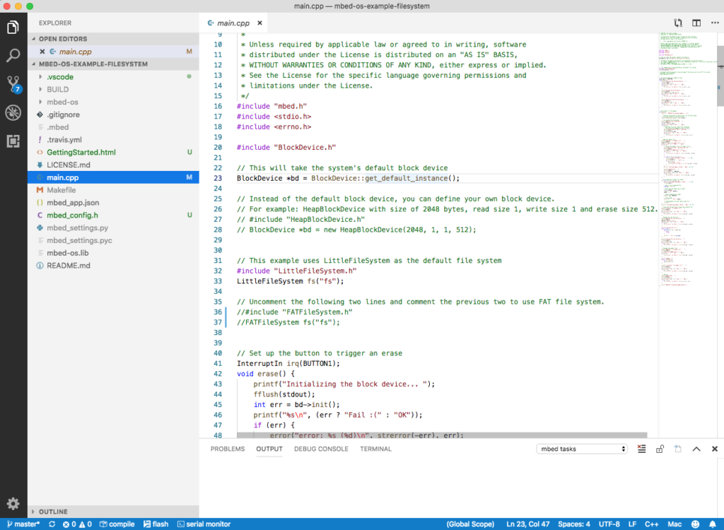
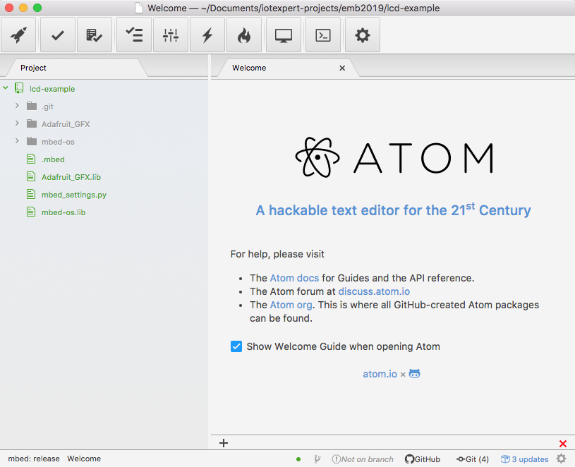
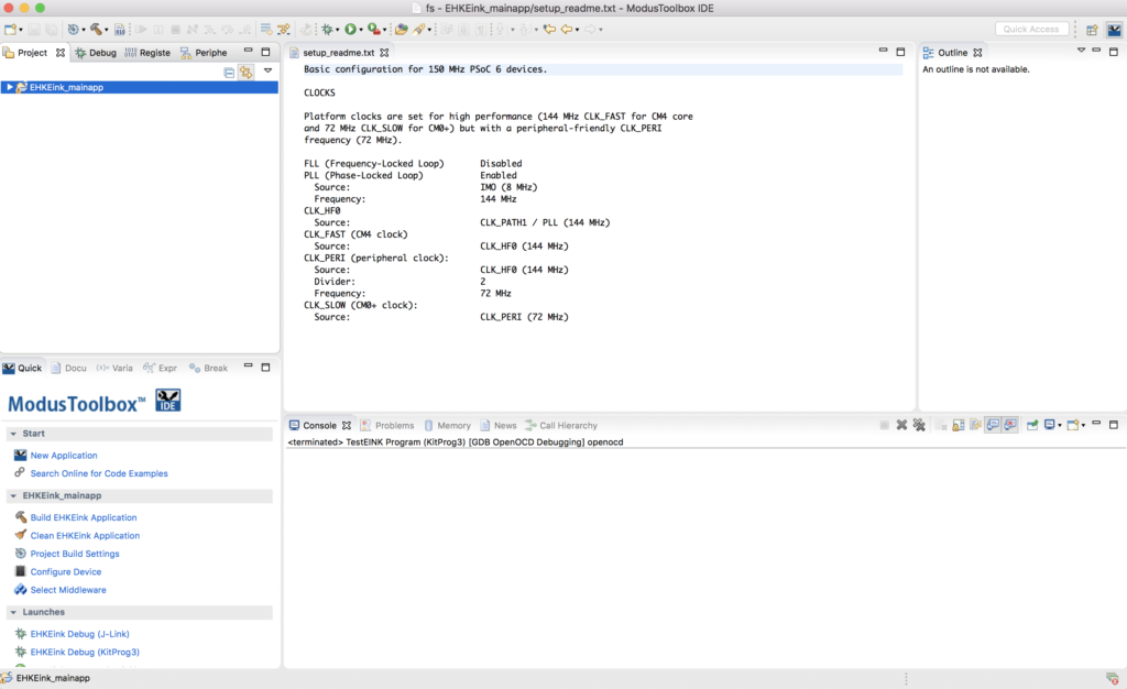
And you should end up with a screen that looks like this. On the left in the workspace explorer you see the main app project. In the middle you see the readme file which explains how this project is configured.
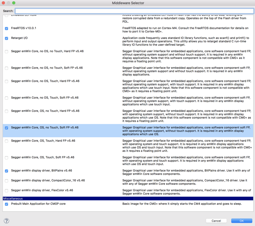
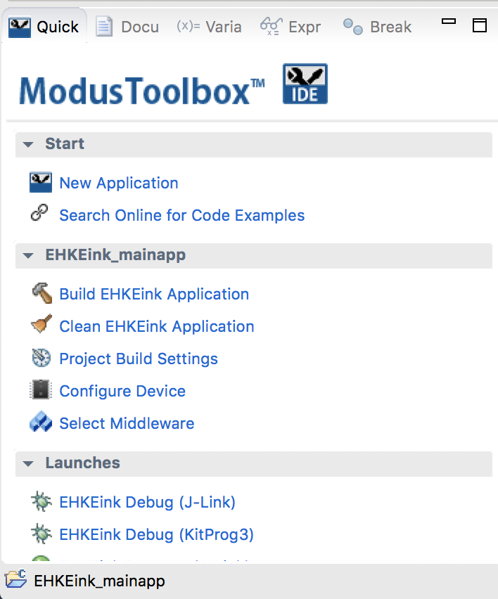
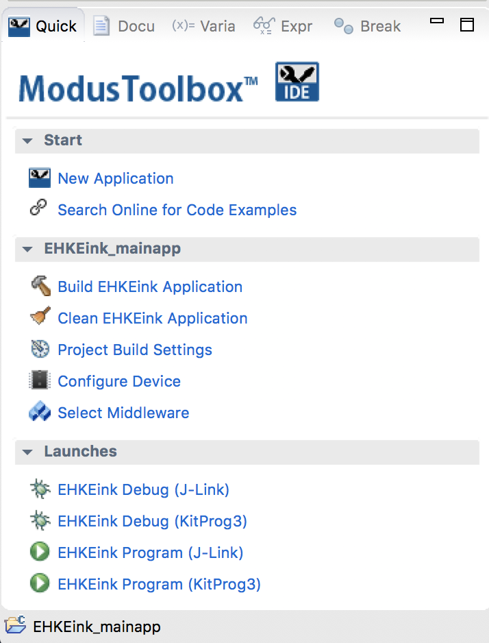
The next step is to add the “Middleware” that we need to make this project work. You can do this by clicking the select Middleware button from the ModusToolbox quick panel.
For this project we need
- FreeRTOS
- Retarget I/O
- Segger emWin Core, OS, no Touch, Soft FP
- Segger emWin display driver BitPlains
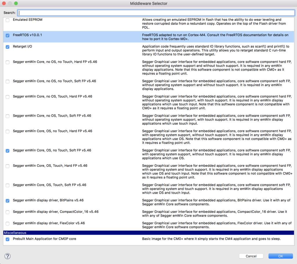
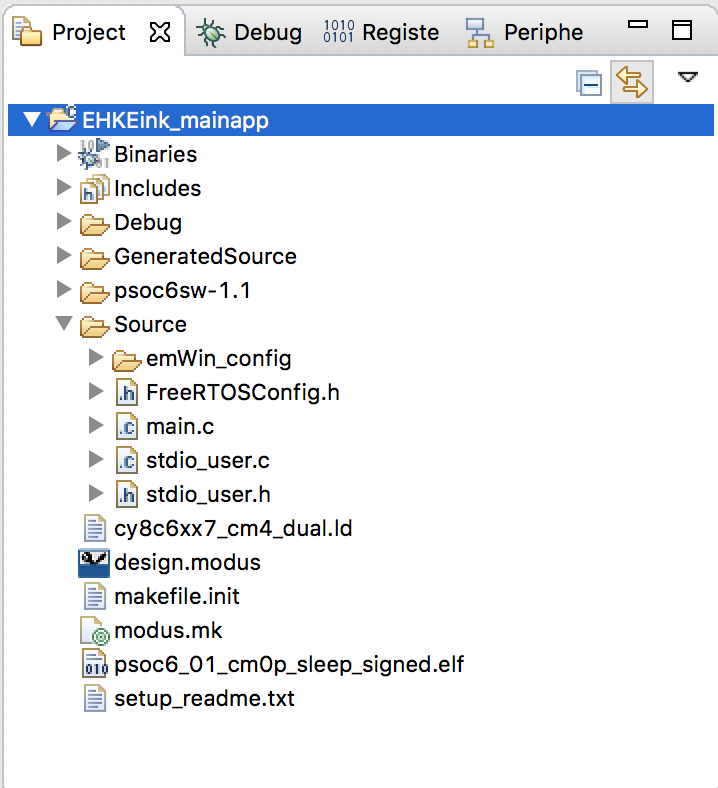
The middleware selector will bring in all of the drivers you selected into your project. You can see that it also adds the FreeRTOS configuration file “FreeRTOSConfig.h” as well as “stdio_user.c” etc. These files endup in the source folder and are for you to edit.
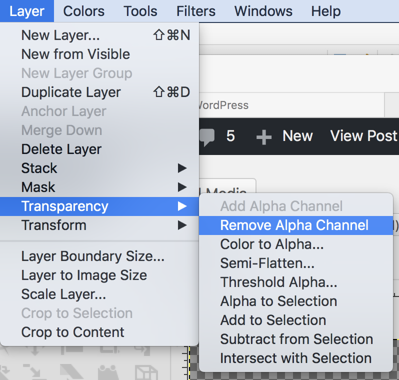
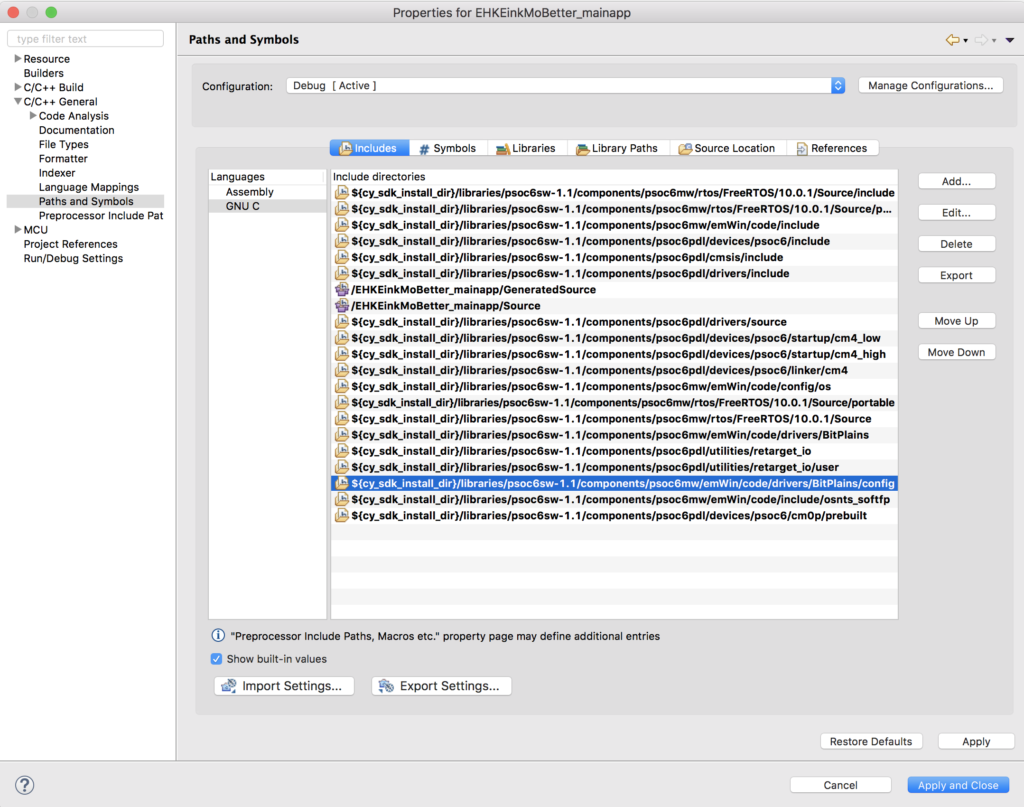
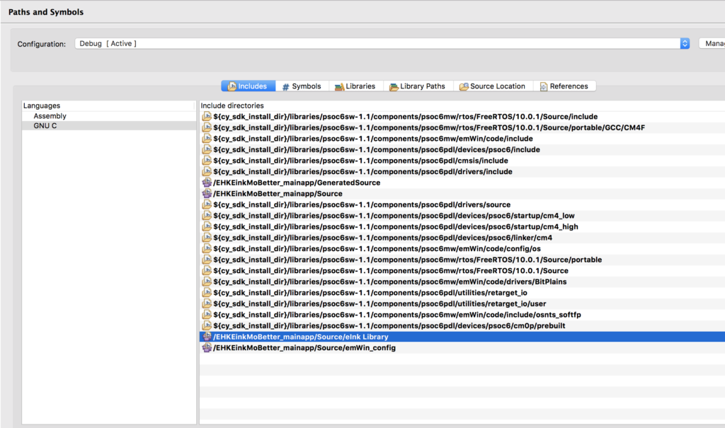
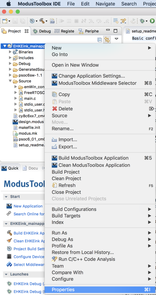
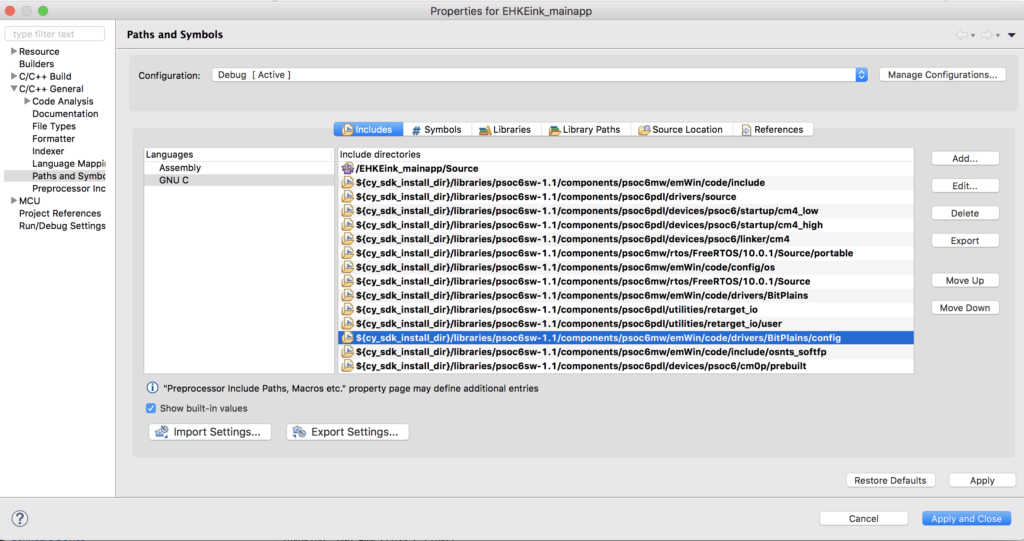
While I was working on this, I found a bug in the emWin middleware, specifically the the configuration files for BitPlains get included twice. To fix this you need to change the project properties and remove the path to “..components/psoc6mw/emWin/code/drivers/BitPlains/config”. To do this, select the project in the workspace explorer then right click and select properties.
Then select “C/C++ General –> Paths and Symbols”. Select the “…BitPlains/config” path and click “Delete”
Configure the device in MTB
Modus Toolbox does not have a “schematic” or a “dwr” like PSoC Creator. In order to achieve the same functionality we built the “Configurator”. This tool will let you setup all of the peripherals in your project. To run it select “Configure Device” in the MTB Quick Panel.
Remember from the PSoC Creator Schematic we need to have:
- A bunch of pins
- A SPI
- A Timer
- Plus I want a UART to connect to standard I/O.
First, click on the “Pins” tab. This lets you set all of the configuration information for each of the pins on the chip. I will go one by one enabling the pins and setting them as digital inputs or output. I am going to give all of the pins that exact same names that they had in the PSoC Creator Project because I know the author of that project used PDL. When you give a pin a name in the configurator it will generate #defines or c structures based on the name. This will make the source code the original PSoC Creator author wrote almost exactly compatible with MTB.
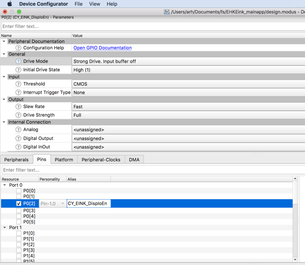
Here is an example of the first output pin which is P0[2] and is named CY_EINK_DispIoEn. For the output pins you need to do four things.
- Enable the checkbox next to the pin name. (in this case P0[2])
- Give the pin a name (CY_EINK_DispIoEn)
- Set the drive mode (Strong Drive, Input buffer off)
- Set the initial state of the pin (High (1))
Now, you need to go one by one turning on all of the output pins (Im not showing you screen shots of all of them)
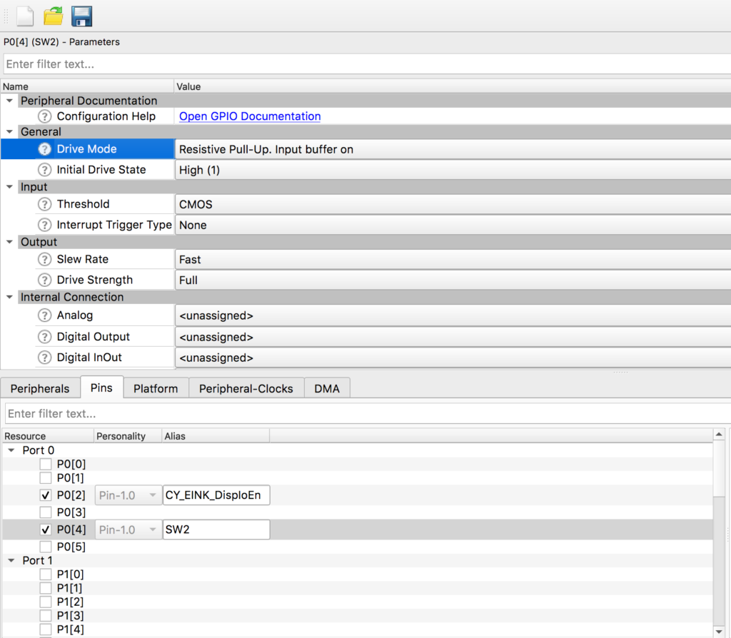
There are two input pins for this project SW2 P0[4] and CY_EINK_DispBusy P5[3]. For these pins I will:
- Enable the pin checkbox
- Give the pin a name (in this case SW2)
- Resistive Pull-Up, Input buffer on. Note for P5[3] the pullup resistor is not needed
Now that the digital pins are configured, you can setup the STDIO Uart. This will be used to send debugging messages to the console Uart which is attached to your computer via a USB<->UART bridge in KitProg 3.
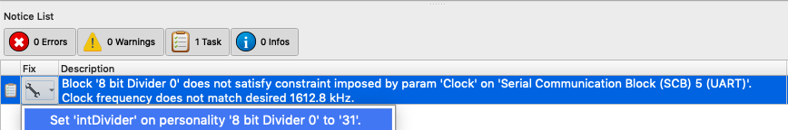
Start by enabling SCB5 and giving it the name “UART”. Make sure that the baud rate is set to 115200 and the rest to 8n1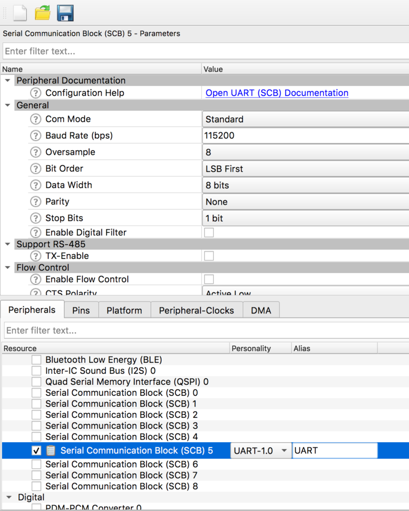
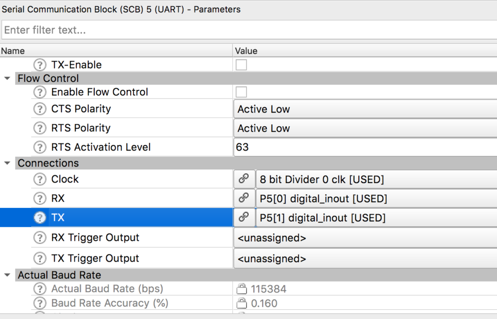
Scroll down the window and pick out the RX and TX Pins plus the clock (any of the 8-bit clock dividers will do. In this case I chose Divider 0)
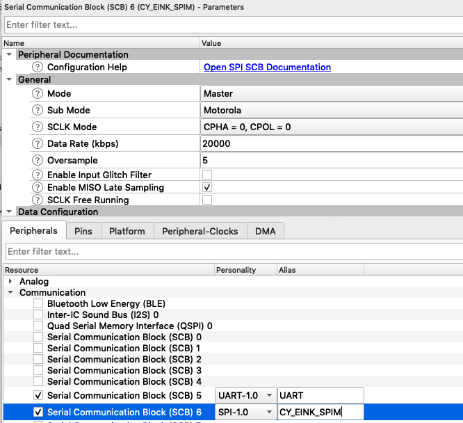
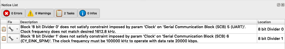
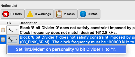
Now, you need to setup the SPI. To do this turn on SCB 6, set it to SPI, give it the name “CY_EINK_SPIM”, set it to “Master”, fix the data rate to 1000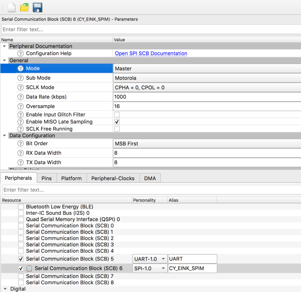
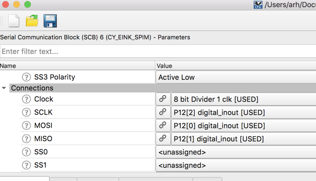
Then scroll down to the “Connections” section and assign the pins
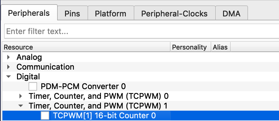
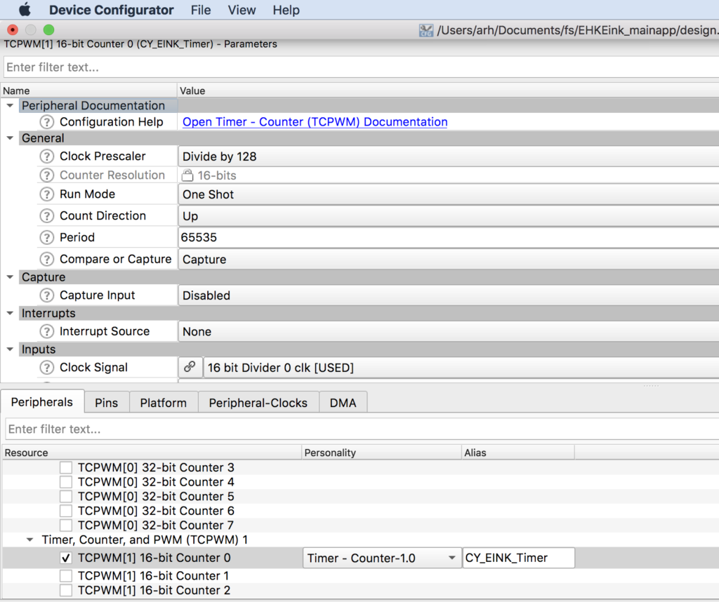
The last bit of hardware we need is a timer with a 1000kHz input clock, in other words a millisecond timer. To do this start by enabling TCPWM[1] 16-bit counter. Call it “CY_EINK_Timer” which was the same name as the PSoC Creator project. Then setup
- As a “Timer Counter”.
- One shot
- Up count
- Period is 65535 (aka the max)
- And pick “Clock signal” as 16 bit Divider
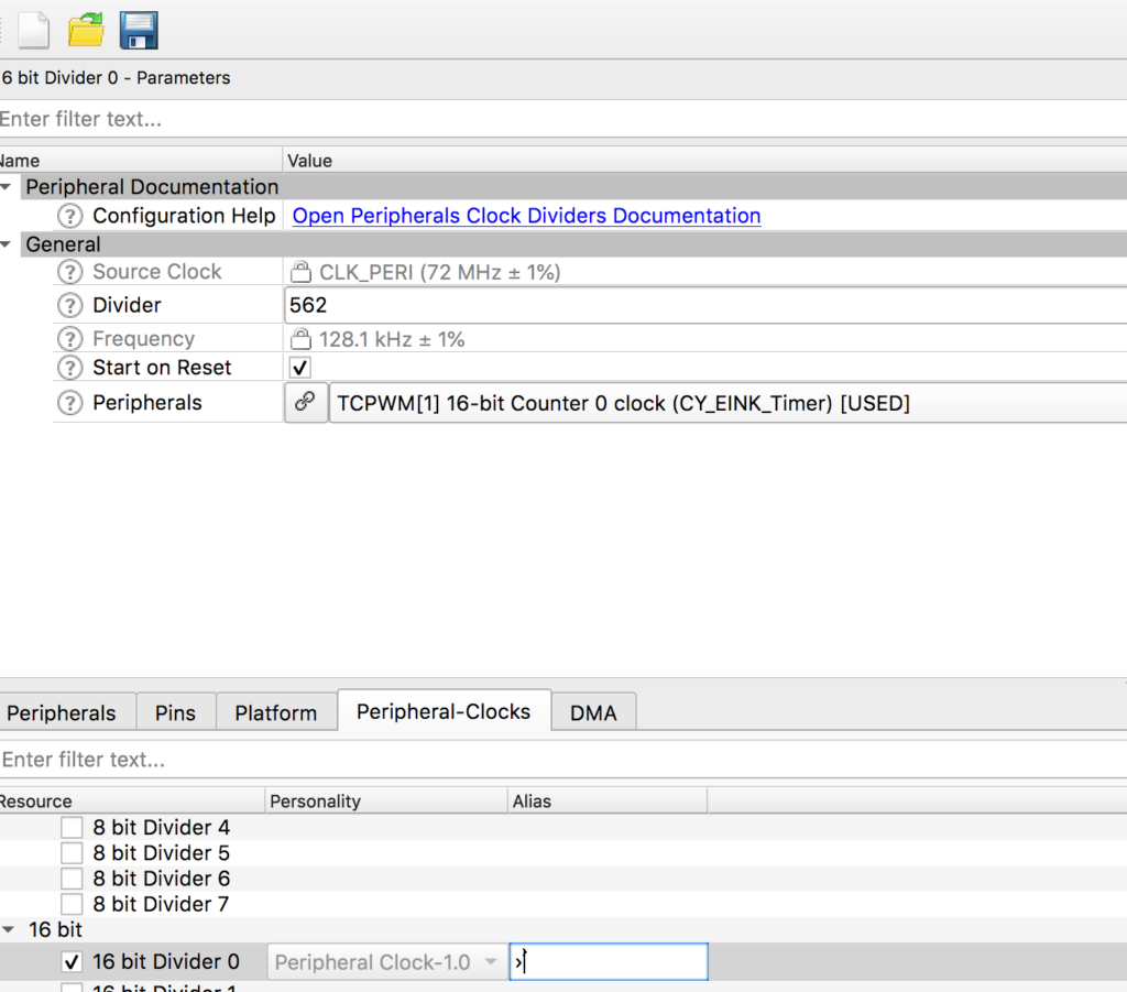
Given that we want it to count milliseconds and the input has a 128 bit pre-divider… we need for the input clock to be setup to 128khz. Click on “Peripheral clocks” then select “16 Bit Divider 0”. Notice that the input frequency is 72Mhz and we need 128Khz… to get this a divider of 562 is required. 72mhz/128khz = 562
Setup FreeRTOS and Standard I/O
The next step is to setup the “plumbing”. In this projet we are using FreeRTOS and Standard I/O. To configure FreeRTOS just edit the “FreeRTOSConfig.h” and remove the “warning”
#warning This is a template. Modify it according to your project and remove this line.
Enable mutexes on line 57
#define configUSE_MUTEXES 1
Make the heap bigger on line 70
#define configTOTAL_HEAP_SIZE 1024*48
Change the memory scheme to 4 on line 194
#define configHEAP_ALLOCATION_SCHEME (HEAP_ALLOCATION_TYPE4)
To enable the UART to be used for Standard I/O, edit “stdio_user.h” and add the includes for “cycfg.h”. Then update the output and input Uart to be “UART_HW” (which is the name you gave it in the configurator)
#include "cycfg.h"
/* Must remain uncommented to use this utility */
#define IO_STDOUT_ENABLE
#define IO_STDIN_ENABLE
#define IO_STDOUT_UART      UART_HW
#define IO_STDIN_UART       UART_HW
Now make a few edits to main.c to
- Add includes for the configuration, rtos and standard i/o
- Create a context for the UART
- Create a blinking LED Task
- In main start the UART and start the blinking LED task.
#include "cy_device_headers.h"
#include "cycfg.h"
#include "FreeRTOS.h"
#include "task.h"
#include <stdio.h>

cy_stc_scb_uart_context_t UART_context;

void blinkTask(void *arg)
{
	(void)arg;

    for(;;)
    {
    		vTaskDelay(500);
    		Cy_GPIO_Inv(LED_RED_PORT,LED_RED_PIN);
    		printf("blink\n");
    }
}
int main(void)
{
    init_cycfg_all();
    __enable_irq();

    Cy_SCB_UART_Init(UART_HW,&UART_config,&UART_context);
	Cy_SCB_UART_Enable(UART_HW);

  	xTaskCreate( blinkTask,"blinkTask", configMINIMAL_STACK_SIZE,  0,  1, 0  );
  	vTaskStartScheduler();
  	while(1);// Will never get here
}
As I edited the code I notice that it can’t find “LED_RED” which made me realize that I forgot to add the LED_RED attached to P0[3] in the configuration. So, I go back and update P0[3] to be LED_RED as strong drive digital output.
Finally just to make sure that it is all working lets program the kit. When I press “EHKEink Program” form the quickpanel…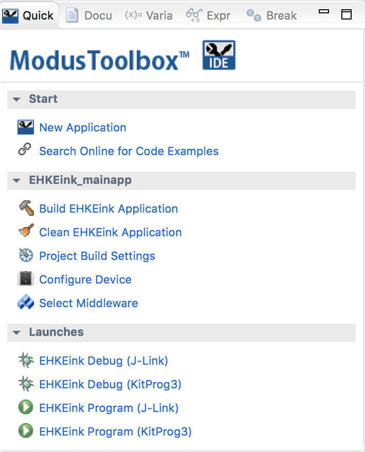
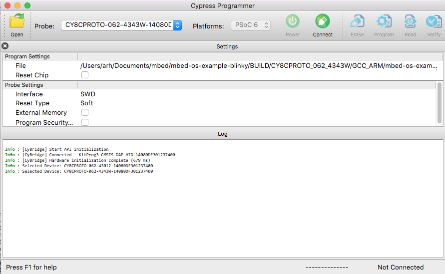
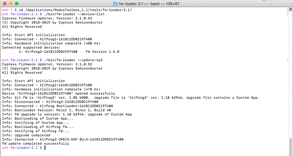
I get this message in the console.
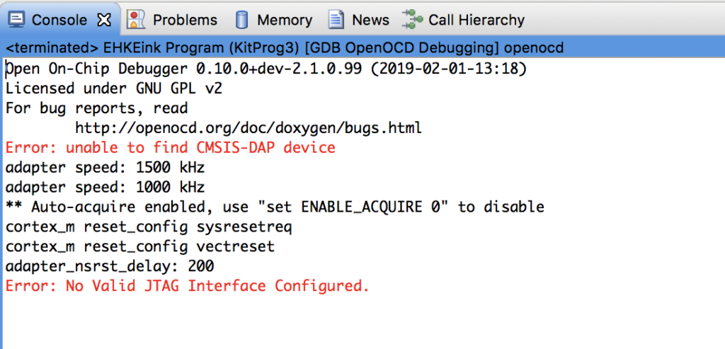
But how can that be? I have my kit plugged in? In order to program your kit using Modus you need “KitProg3”. PSoC Creator can program you kit with KitProg3 only if it is in the CMSIS-DAP HID mode. To switch you development kit to KitProg3, you can use the program “fw-loader” which comes with MTB. You can see what firmware you have by running “fw-loader –device-list”. To change to KitProg 2 run “fw-loader –update-kp2” and to update to KitProg3 run “fw-loader –update-kp3”
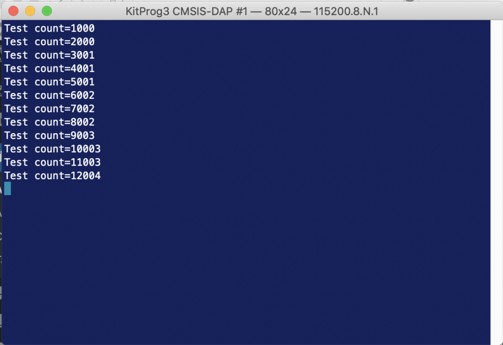
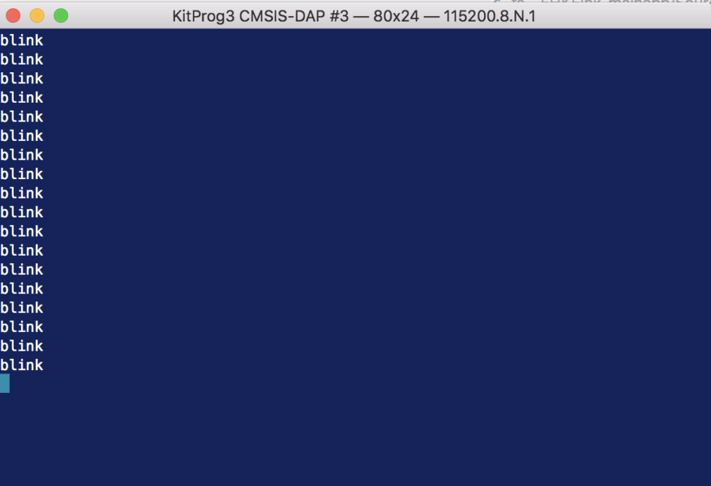
Now when i program I get both the LED blinking and the console printing blink.
Copy the files into the MTB project
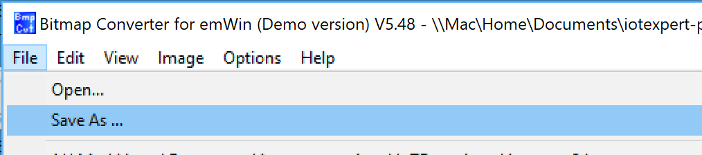
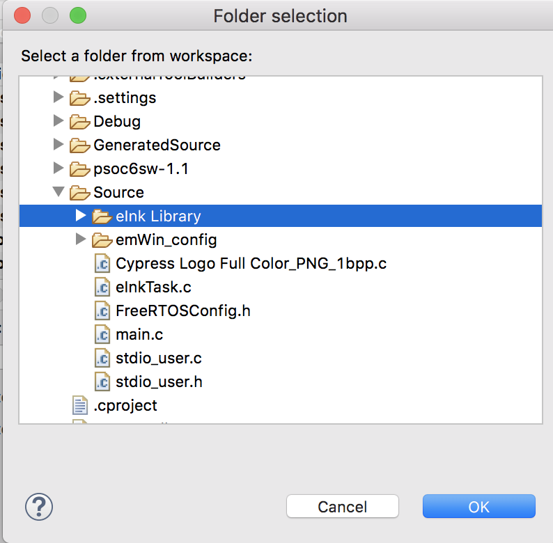
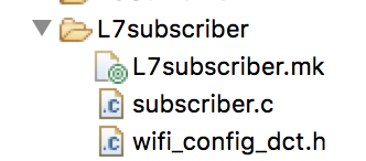
Next, I want to bring over the drivers from the PSoC Creator project. They reside in folder called “eInk Library” inside of the PSoC Creator project. You can copy them by navigating to the PSoC Creator workspace, then typing ctrl-c in the File Explorer, then clicking the “Source” directory in your Eclipse WorkSpace explorer and typing ctrl-v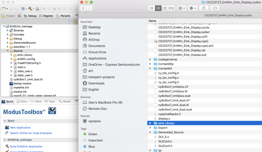
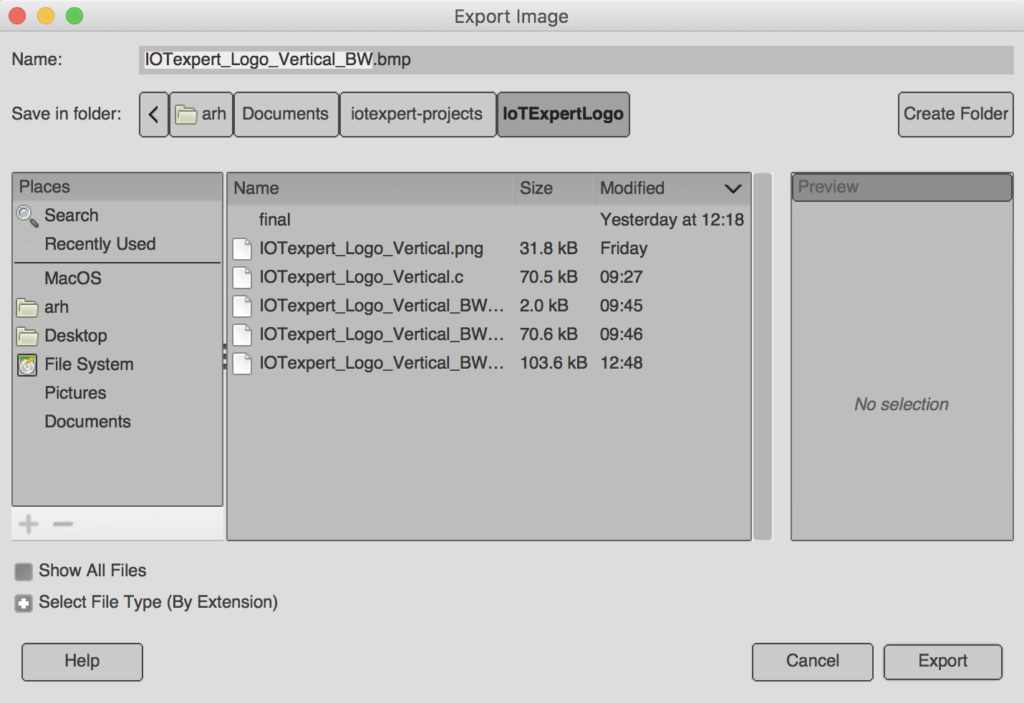
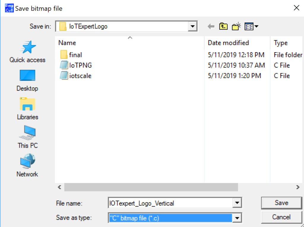
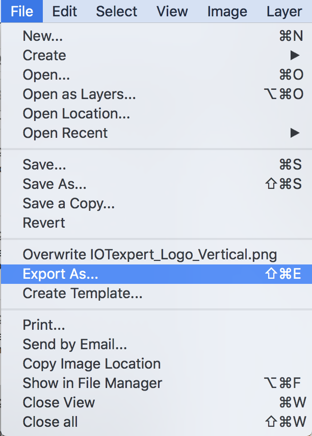
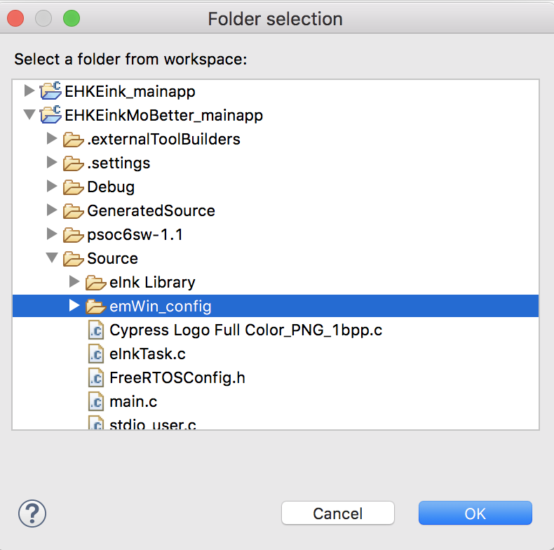
You will also need the four files “GUIConf.c”, “GUIConf.h”, “LCDConf.h” and “LCDConf.c”. Copy and paste them into the emWin_config directory.
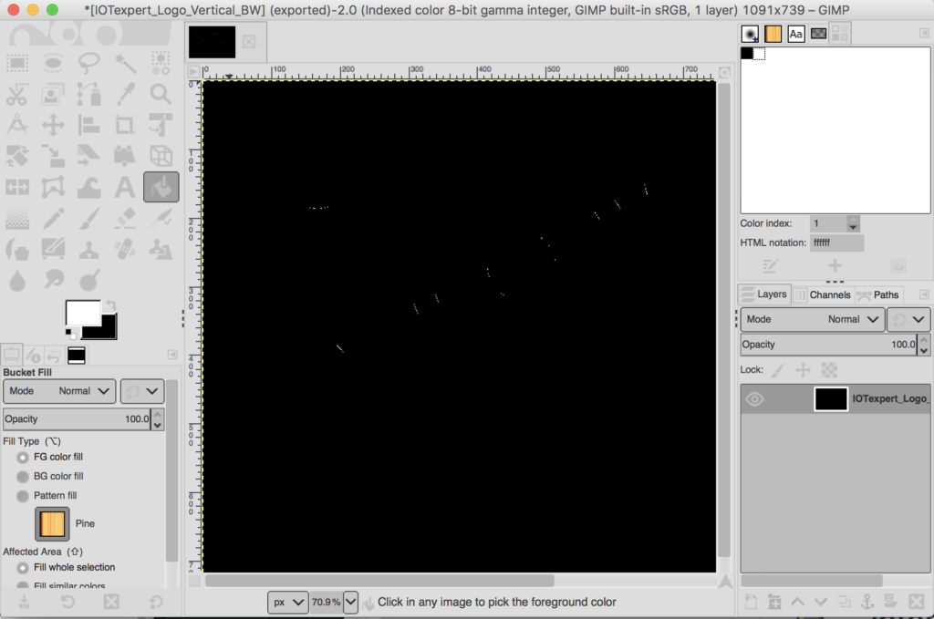
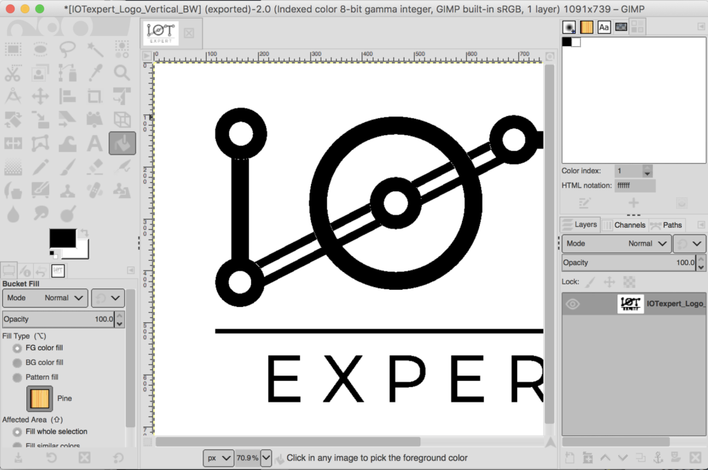
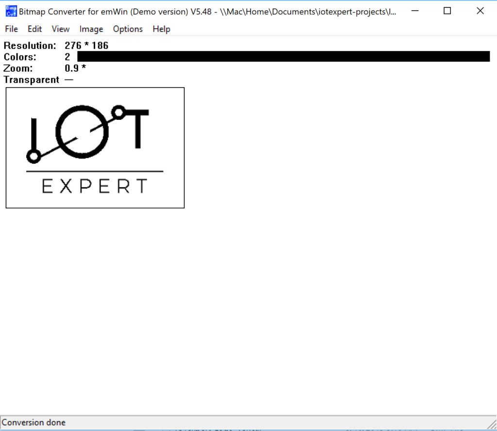
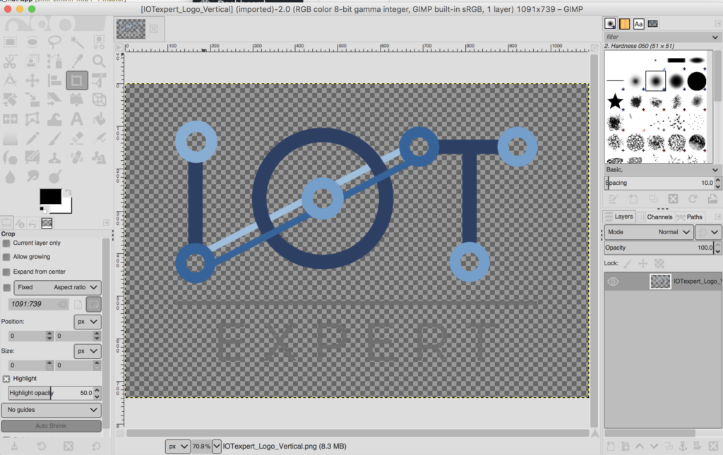
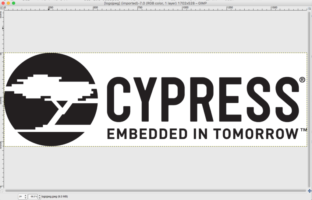
For this project I am going to use the code that existed in “main.c” from the original PSoC Creator project. But I want it to be a task (and a few other changes). To facilitate things, I will copy it as well. Then rename it to eInkTask.c. And finally, the file “Cypress Logo Full Color_png1bpp.c” needs to be copied as well.
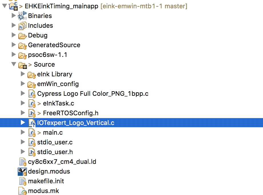
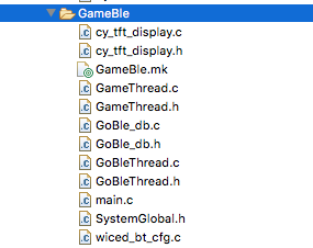
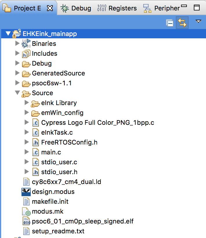
After all of those copies you should have your project looking something like this:
Port the Drivers and eInkTask
Now we need to fix all of the driver code. Big picture you will need to take the following actions.
- Update the Project settings to include the new folders (emWin_config and emWin Library)
- Replace the PSoC Creator #include <project.h> with MTB #include “cycfg.h”
- Update the files to have #include “FreeRTOS.h” and “task.h” where appropriate
- Replace all of the CyDelay’s with vTaskDelays
- Fix the old PSoC Creator component calls for the timer with PDL calls
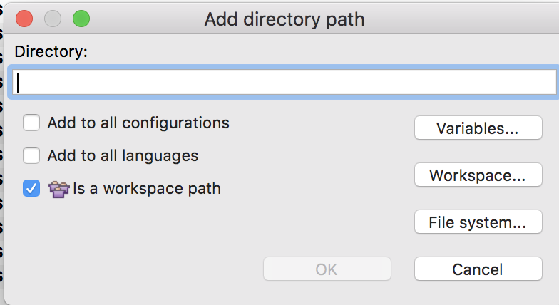
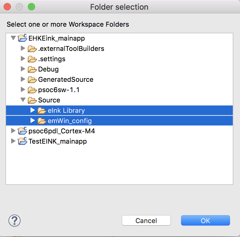
First go to the project settings (remember, click on the project then select properties). Then pick “C/C++ Build Settings” then “GNU ARM Cross C Compiler” and “includes” Press the little green “+” to add the new directories
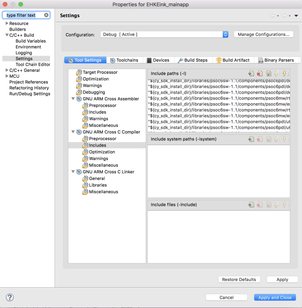
You can select both directories at once.
Next edit eInkTask.c
Update #include “project.h” to be #include “cycfg.h” on line 59. Add “FreeRTOS.h” and “task.h” to the includes.
#include "cycfg.h"
#include "GUI.h"
#include "pervasive_eink_hardware_driver.h"
#include "cy_eink_library.h"
#include "LCDConf.h"
#include "FreeRTOS.h"
#include "task.h"
#include <stdio.h>
Find and replace “CyDelay” with “vTaskDelay”
Update the PSoC Creator component call _Read with the pdl calls Cy_GPIO_Read on line 661
void WaitforSwitchPressAndRelease(void)
{
    /* Wait for SW2 to be pressed */
    while(Cy_GPIO_Read(SW2_PORT,SW2_PIN) != 0);

    /* Wait for SW2 to be released */
    while(Cy_GPIO_Read(SW2_PORT,SW2_PIN) == 0);
}
Update the “int main(void)” to be “void eInkTask(void *arg)” on line 687
void eInkTask(void *arg)
{
	(void)arg;
Remove ” __enable_irq(); /* Enable global interrupts. */” from the old main on line 695.
In the file cy_eink_psoc_interface.h
Update the #include <project.h> to be #include “cycfg.h” on line 59.
In the file cy_eink_psoc_interface.c
Create a context for the SPIM by adding on line 58:
cy_stc_scb_spi_context_t CY_EINK_SPIM_context;
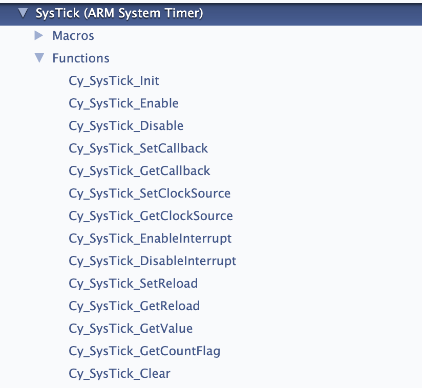
The three timer functions in this file use the old PSoC Creator component timer interface APIs rather than the PDL interface. So you will need to change Cy_EINK_TimerInit, Cy_EINK_GetTimeTick and Cy_EINK_TimerStop to use PDL.
Here is Cy_EINK_TimerInit
void Cy_EINK_TimerInit(void)
{
    /* Clear the counter value and the counter variable */
    //CY_EINK_Timer_SetCounter(0);

    Cy_TCPWM_Counter_Init (CY_EINK_Timer_HW, CY_EINK_Timer_NUM, &CY_EINK_Timer_config);
    Cy_TCPWM_Counter_SetCounter	(	CY_EINK_Timer_HW, CY_EINK_Timer_NUM,0);

    Cy_TCPWM_Enable_Multiple(	CY_EINK_Timer_HW,CY_EINK_Timer_MASK);
    /* Initialize the Timer */
    //CY_EINK_Timer_Start();
    Cy_TCPWM_TriggerStart	(	CY_EINK_Timer_HW,CY_EINK_Timer_MASK);
}
And Cy_EINK_GetTimeTick
uint32_t Cy_EINK_GetTimeTick(void)
{
    /* Variable used to store the time tick */
    uint32_t timingCount;

    /* Read the current time tick from the E-INK Timer */
    //timingCount = CY_EINK_Timer_GetCounter();
    timingCount = Cy_TCPWM_Counter_GetCounter	(CY_EINK_Timer_HW, CY_EINK_Timer_NUM);


    /* Return the current value of time tick */
    return(timingCount);
}
And Cy_EINK_TimerStop
void Cy_EINK_TimerStop(void)
{
    /* Stop the E-INK Timer */
    //CY_EINK_Timer_Disable();
	Cy_TCPWM_Counter_Disable(CY_EINK_Timer_HW, CY_EINK_Timer_NUM);

}
In the file LCDConf.h change the include to stdint.h and make the type uint8_t instead of uint8
#include  <stdint.h>

void LCD_CopyDisplayBuffer(uint8_t * destination, int count);
In the file LCDConf.c remove the #include “syslib/cy_syslib.h” (I have no idea why it is/was there) and then add “#include <stdint.h>” On line 219 change “uint8” to be “uint8_t”
void LCD_CopyDisplayBuffer(uint8_t * destination, int count)
In the file cy_eink_fonts.h change the “#include <project.h>” to be
#include <stdint.h>
#include <stdbool.h>
In main.c add an external reference to the eInkTask on line 36 (yes this is really ugly Alan)
extern void eInkTask(void *);
And start the eInkTask on line 58. Notice that I put in 10K for the stacksize… but I dont actually know how much it takes.
xTaskCreate( eInkTask,"eInkTask", 1024*10, 0, 1, 0 );
Program & Test the MTB Project
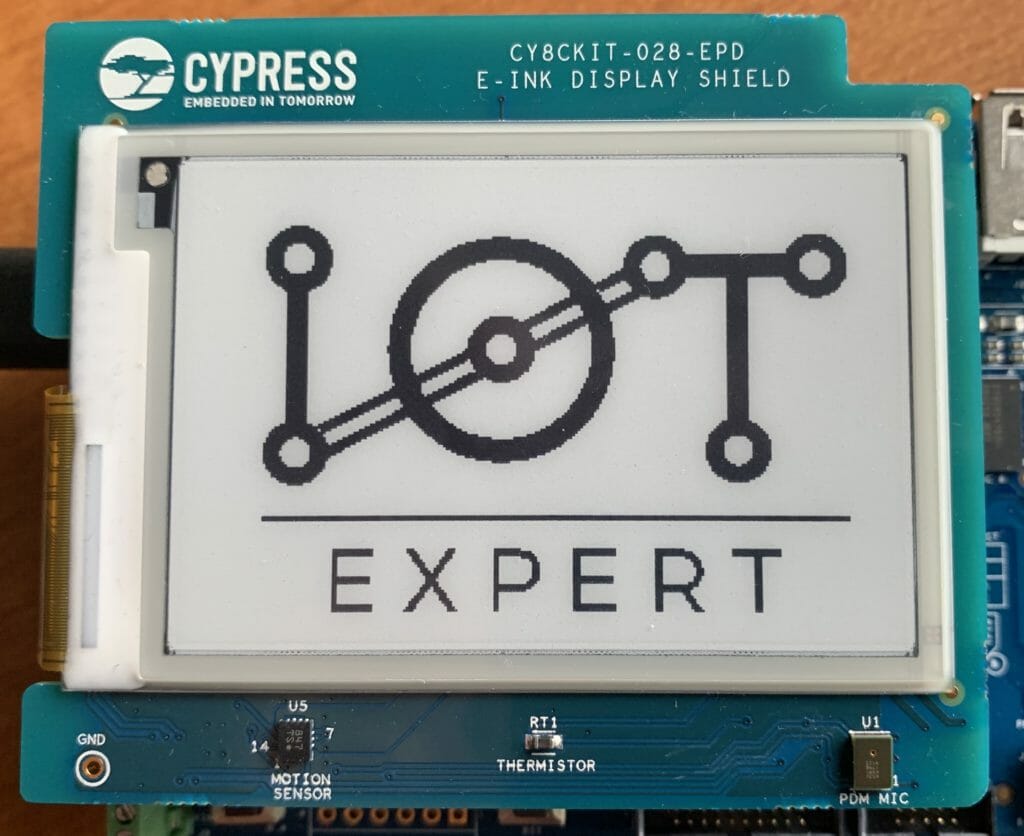
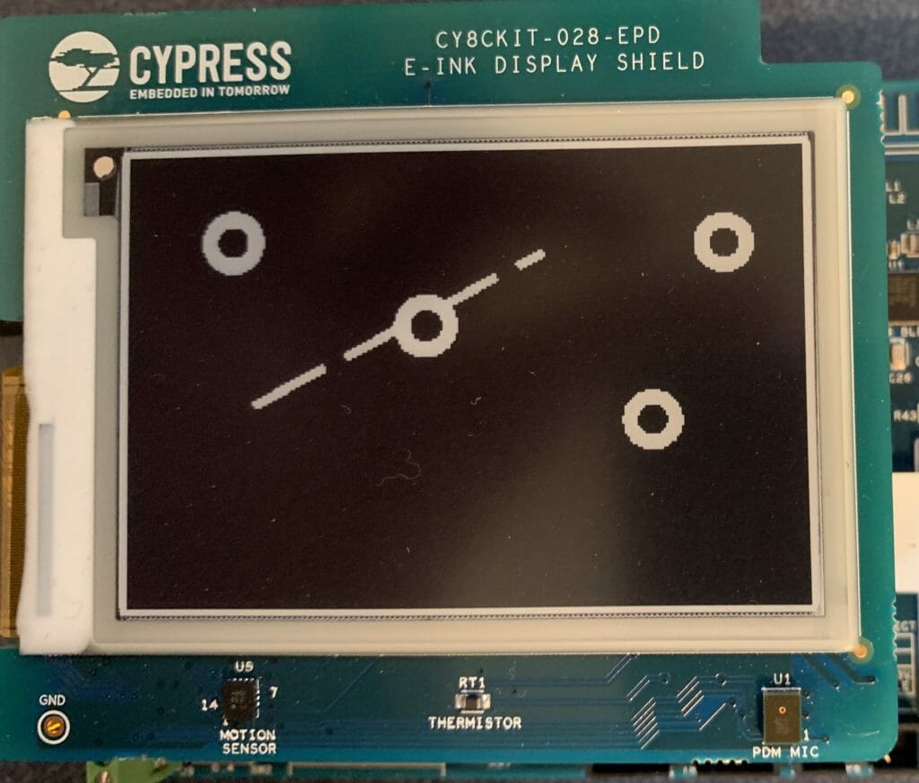
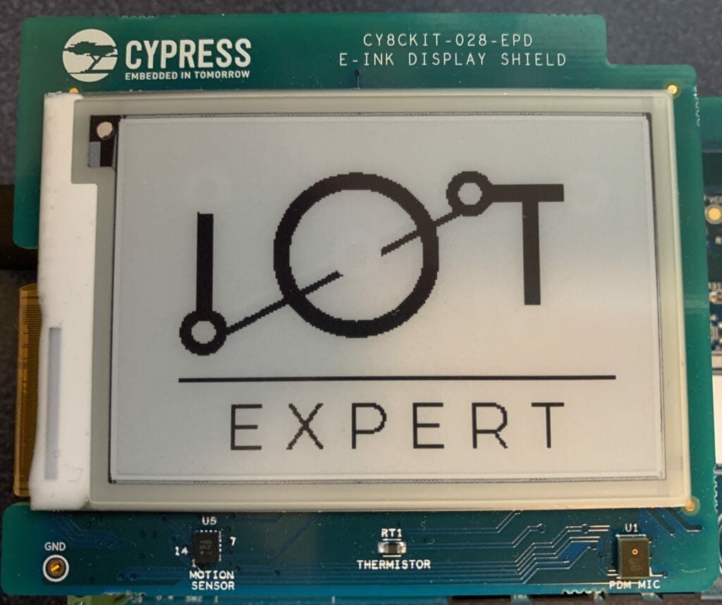
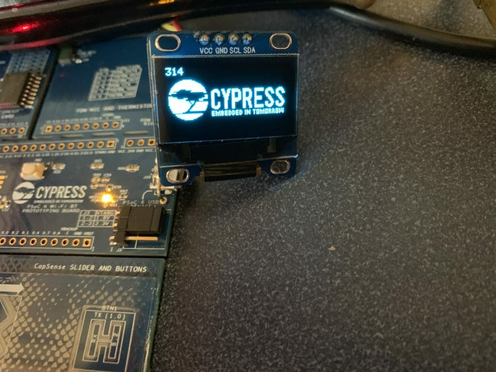
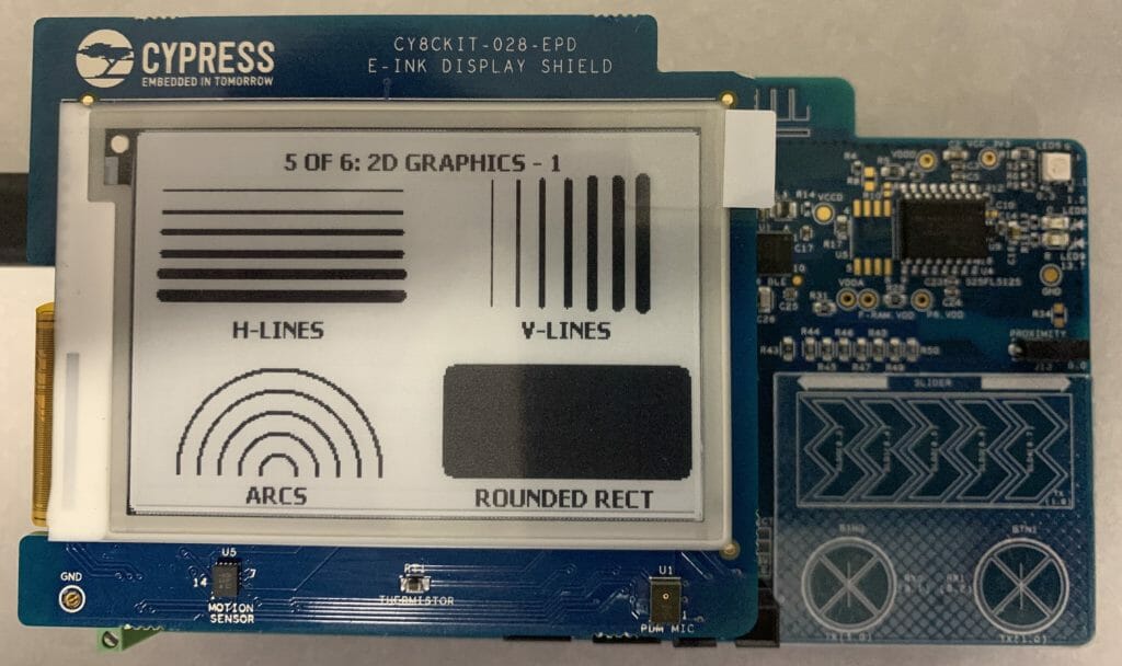
When you program the development kit you should have
- A blinking RED LED
- The ability to scroll through a bunch of screens using the SW2 button.
Here is a picture
In the next article I will:
- Speed up the SPI
- Get rid of the hardware timer
- Explain more about the EINK.