Infineon SupIRbuck – Low Voltage/High Current Measurement

Summary

This article will show you the steps to produce 12A from and IRDC3894.  It also discusses low voltage high current measurement and burden voltage.

The Story

In the last few weeks I have been working on a TypeC to Infineon SupIRbuck power supply that will turn 20V@3A into 5V@12A.

In that process I have been working with a Keithley 2380-500-15 which can act as a load simulator for my design.  The 15 in name means that it can pull 15A which should be more an adequate to test my design.  Unfortunately when I was looking at the specs, I read the part about “15A” but not the part about the “Min Operating Voltage in the 15A range = 4.5V”

And what I really should have bought (and now have) is a 2380-120-60

Big Resistors

But I really wanted to be able to measure the current coming out of the IR3894.  So, I decided to buy some “Big” resistors.  Well they are not actually high resistance, but they are HIGH power. 35W and 50W.  Unfortunately they are also $4 each.  Here is a 0.33Ω 50W resistor.  (I will totally understand the value of that giant heat sink later on in this article)

My measurement setup looks like this:

And actually looks like this terrible mess:

Start the measurements

I bought 7 different resistors ranging from 0.1Ω to 1Ω.  This means that I should be able to get something like this table.  Note that the 0.1Ω is marked in red because it exceeds the current limit of my multimeter. (i.e. don’t do that)

V R A W Rating
1.2 0.10 12.0 14.4 35
1.2 0.15 8.0 9.6 50
1.2 0.20 6.0 7.2 35
1.2 0.33 3.6 4.4 50
1.2 0.50 2.4 2.9 35
1.2 0.75 1.6 1.9 50
1.2 1.00 1.2 1.4 50

I wasn’t exactly sure what was going to happen so I decided to start with the 0.33Ω resistor

I was hoping to get 1.2V/0.33Ω = 3.6A yet I end up with 1.99A where is my other 1.6A?

I put in a 0.1Ω, 0.15Ω and 0.75Ω and measured the current.  Then I calculate the effective resistance of the system and it turns out that there is essentially another 0.27Ω in series with my R1

V=I(R1+Rb)

V/I-R1 = Rb

V A R1Ω RbΩ R1+RbΩ
1.2 2.0 0.33 0.27 0.60
1.2 3.16 0.10 0.28 0.38
1.2 2.85 0.15 0.27 0.42
1.2 1.175 0.75 0.27 1.02

Where in the world is the other 0.27Ω?

Melt the Probe

This leads me to the great idea that is just the lead wires, and that I ought to just pull out the resistor and see what happens.  Well, what happens is that I melt the probe, and I still don’t get numbers that make sense.

Burden Voltage

The real story is, of course, that digital multimeters are hardly “ideal” and that when you are measuring current what you are really doing is measuring the voltage across a “shunt resistor”.  A shunt resistor is just a small valued highly precise resistor.  The voltage across this resistor is also known as the burden voltage (which is why I called it Rb above).  Here is a picture out of the Keysight documentation.

But how big is that resistor?  Well, unfortunately it is not specified directly in the documentation.  But, when you look at the data sheet you find that the maximum burden voltage is 0.5V at 10A.

This means that shunt resistor is no more than 0.5v/10A=0.05Ω.  I just ordered a new Keithley DAQ6510 Digital Acquisition System Multimeter (which Im very excited about) that has the following table in documentation where it says the shunt resistor is 100mΩ for the 3A range.

Measure the Lead Resistance

So now we know that the shunt resistor is something like 0.05Ω.  That means the rest of the resistance has to be in the test setup.  So

V=(R1 + Rl + Rb)*I … the lead resistance + the shunt resistor + the actual resistor.  I go ahead and calculate what the lead resistance with several different resistors.

This means the resistance of my lead wires must be something like 0.23Ω

V A R1 Rl Rb R1+Rb+Rl VR1 VRl VRb
1.2 2.00 0.33 0.23 0.04 0.37 0.66 0.46 0.08
1.2 3.16 0.10 0.23 0.04 0.15 0.32 0.73 0.16
1.2 2.85 0.15 0.23 0.04 0.19 0.43 0.66 0.12
1.2 1.18 0.75 0.23 0.04 0.79 0.88 0.27 0.05

Again I start to look for the lead wire resistance … 0.6Ω for the melted lead.  Curious.

It is pretty easy to get some crazy measurements.  2.7Ω just pushing two banana plugs together (though you can see it blinking)

If I measure the red banana plug wire looped back the measurement is 0.016Ω – OK that is pretty small

And the black one is almost the same.

After some experimenting mixing and matching cables together the lowest I manage to get in a configuration that I can actually plug together is 0.15Ω which gave me 7.8A.

So where does this leave me?  To tell you the truth it leaves me a bit frustrated.  I really wanted to get 12A out of my setup (which is what it should be able to do).  But the most I can safely measure is 10A.  And the lowest combination of resistors I seem to be able to get is 0.15Ω.  So I decide to solder the 0.1Ω resistor straight into the board and see what happens. (yes that is some ugly soldering)

And now Im really frustrated because when I turn on the bench power supply I get 9.9V and 0.6A … even though it is set for 12V

And when I look at the output voltage I get 0.4V.  Which means it isn’t working.  Why?  I don’t know…. which is beyond annoying.  Walk away now I say to myself (actually that was my wife yelling at me 🙂 )

24 Hours Later

After sleeping on it, I remember that the Enable pin is used as an “Under Voltage Lock Out”.  The purpose of the UVLO is to not turn on until the input voltage has enough power to supply the system.  Given that I am am asking for 12A I realize… maybe I need to “enable” later in the power supply voltage rise.

So what I do I solder in a jumper to “Enable” then I press fit it into the ground.  Then turn on the power supply.  I measure the output as 0V.  That is good.  Then pull the enable jumper wire and let the IR3894 turn on.

Sure enough.  When I look at the input it gets to 12V@1.4A and the output is still steady at 1.2v.  And my 0.1Ω is very hot.  I suppose that heatsink tab is there for a  reason.

I know from Ohms law that I am getting 12A@1.2V.  So the IR3894 seems to do the trick!

Cypress Type-C Barrel Connector Replacement + Infineon Buck DC/DC (Part 3)

Summary

This article walks you through the steps to test the CY4533 Type-C BCR & IR3894 under the load conditions from 1A to 12A.  In the previous article, I supplied power to the IR3894 using a bench top power supply.  For this set of experiments I will use a Type-C wall wart connected to the Cypress 4533 BCR development kit to supply power.

Test the BCR

The first thing that I do is connect the whole mess together like this:

Here is how it looks on my desk.  Note that the Keithey can measure current and voltage… but that I don’t have a way in this setup to measure either the voltage/current from the power supply or the current out of the CY4533

I step the output load from 1A to 12A in 1A increments.  I am super happy to see that the output voltage of the IR3894 is perfectly regulated to 1.198V.  It is also interesting to see that the Type-C power supply is able to keep the voltage within 3.25% of nominal even when I am using 12A on the IRDC3894 output (probably around 1.5A from the Type-C)

Measure the Input Current

In the previous article I used the current measurement from the Keithley bench top power supply.  In the setup above I don’t have a way to measure the actual input current.  To fix this put my new Keithley DAQ6510 in series with the IRDC3894 board.  Like this:

Then I step through the 1A-12A load conditions.  Once again the IR3894 provide a very well regulated voltage and current (exactly the same as before so I didn’t write them down)

Here is a table with the data from the previous post (without the Type-C power supply) versus the Type-C power supply.

2230-30-1 Power Supply With 6510 current meter in input path
Vin Iin Win Vout Iout Wout Eff Vin Iin Win Eff-C Loss
12 0.27 3.24 1.198 0 0 0%
12 0.129 1.548 1.198 0.998 1.195604 77% 11.91 0.129 1.53639 77.8% -0.6%
12 0.239 2.868 1.198 1.998 2.393604 83% 11.8 0.242 2.8556 83.8% -0.4%
12 0.345 4.14 1.198 2.998 3.591604 87% 11.7 0.352 4.1184 87.2% -0.5%
12 0.454 5.448 1.198 3.998 4.789604 88% 11.59 0.467 5.41253 88.5% -0.6%
12 0.564 6.768 1.198 4.999 5.988802 88% 11.47 0.586 6.72142 89.1% -0.6%
12 0.677 8.124 1.198 5.998 7.185604 88% 11.36 0.709 8.05424 89.2% -0.8%
12 0.792 9.504 1.198 6.998 8.383604 88% 11.25 0.837 9.41625 89.0% -0.8%
12 0.909 10.908 1.198 7.998 9.581604 88% 11.13 0.97 10.7961 88.8% -0.9%
12 1.029 12.348 1.198 8.998 10.779604 87% 10.95 1.115 12.20925 88.3% -1.0%
12 1.152 13.824 1.198 9.999 11.978802 87% 10.85 1.258 13.6493 87.8% -1.1%
12 1.277 15.324 1.198 10.998 13.175604 86% 10.8 1.401 15.1308 87.1% -1.1%
12 1.406 16.872 1.198 11.997 14.372406 85% 10.68 1.558 16.63944 86.4% -1.2%

These measurements use 1A/3A range on the Keithley DAQ6510 DMM, which means that they have a 100mΩ shunt resistor in series which drops the voltage by V=IR or about 0.1-ish volts.  This explains most of the difference from the Power Supply to the Type-C setup.

It is actually very interesting to look at the data to see the impact of lowering the input voltage on the efficiency of the IR3894.  It appears that at the highest load and lowest input voltage the efficiency is down by 1.2%

Watch the Sunrise

While I was sitting there at my desk thinking about what to do next, I decided that the best thing to do was go sit in my hottub and watch the sunrise on God’s country.

USB C Power Meter Tester

I was hoping to be able to measure the input current and voltage from the Type-C power supply so that I could calculate the efficiency of the CY4533 EZ BCR.  And as a result the efficiency of the whole system.  There wasn’t a place on the Type-C development kit to make these measurements, but the Cypress Apps manager for Type-C – Palani – said I should buy something like this from Amazon.


So I did.  You can plug it into Type-A or Type-C and it will tell you how much V/I are coming out.  In the picture below you can see 20.4v@0.11A

Even better it has a handy-dandy mode where it can display Chinese?

Here is a picture in my actual setup:

And a picture of the whole crazy setup.

Now I step through my 12 load conditions from 1A to 12A and record the V/I from the Fluke and the USB Power Tester.

Here is the data in table form with power and efficiency added.

Type C Power Tester
Vin Iin Win Eff-No Meter
11.99 0.15 1.7985 66.5%
11.95 0.26 3.107 77.0%
11.92 0.36 4.2912 83.7%
11.88 0.48 5.7024 84.0%
11.85 0.59 6.9915 85.7%
11.82 0.7 8.274 86.8%
11.79 0.82 9.6678 86.7%
11.75 0.94 11.045 86.8%
11.71 1.07 12.5297 86.0%
11.68 1.2 14.016 85.5%
11.64 1.33 15.4812 85.1%
11.6 1.46 16.936 84.9%

Next, I plot the new data with the previous two plots.  Obviously, it is screwed up.  I would bet money that the data points at 2A, 4A and 12A are wrong.  But, I don’t think that it is worthwhile to take steps to figure out the real current.  So, I suppose that is what you get from a $19 power meter.

Efficiency of CY4533 EZ-PD BCR

I had really wanted to measure the efficiency of the BCR setup.  To do that I needed to be able to measure the output power (V/I) and the input power (V/I).  Unfortunately the power meter doesn’t seem to be very good… so I suppose that I will have to wait to build my real board where I can install some power jumpers the real numbers.

Cypress Type-C Barrel Connector Replacement + Infineon Buck DC/DC (Part 2)

Summary

In this article I will show you how to use a Keithley 2380 (actually two different ones) to test the output of the IRDC3894 12V->1.2V 12A buck development kit.

The Story

To this point I have written several articles about my process of designing a power supply for my new IoT device.  It needs to provide for quite a bit of power, actually 60W is what I am planning on.  I really wanted to make sure that the IR3894 chip would do what it says it would, specifically supply 12A.  The development kit is pretty simple.  There are two banana plug to  provide power to Vin and two banana plus for the load.

For this round of tests I will Keithley 2230-30-1 to provide power and I will use my Keithley 2380-120-60 to serve as the load.

The two mini grabbers are attached to to remote sensing terminals on the Keithley 2380.

After I had it all hooked up I went in 1A increments from 0 to 12A, then I went in 0.1A increments until I ran out of input power.

Here is the actual data table.  Note that I added columns to show the calculated input power.  And I calculated the efficiency of the system Wout/Win

Vin Iin Win Vout Iout W Eff
12 0.27 3.24 1.198 0 0 0%
12 0.129 1.548 1.198 0.998 1.195604 77%
12 0.239 2.868 1.198 1.998 2.393604 83%
12 0.345 4.14 1.198 2.998 3.591604 87%
12 0.454 5.448 1.198 3.998 4.789604 88%
12 0.564 6.768 1.198 4.999 5.988802 88%
12 0.677 8.124 1.198 5.998 7.185604 88%
12 0.792 9.504 1.198 6.998 8.383604 88%
12 0.909 10.908 1.198 7.998 9.581604 88%
12 1.029 12.348 1.198 8.998 10.779604 87%
12 1.152 13.824 1.198 9.999 11.978802 87%
12 1.277 15.324 1.198 10.998 13.175604 86%
12 1.406 16.872 1.198 11.997 14.372406 85%
12 1.42 17.04 1.198 12.098 14.493404 85%
12 1.434 17.208 1.198 12.198 14.613204 85%
12 1.448 17.376 1.198 12.297 14.731806 85%
12 1.462 17.544 1.198 12.398 14.852804 85%
12 1.477 17.724 1.198 12.498 14.972604 84%
12 1.49 17.88 1.198 12.59 15.08282 84%

When I plot the data there is something sticking out like a sore thumb.  WTF?  At first I assume that I typed in the wrong number when I transposed the hand written data to the spreadsheet.  So I went and looked at the data table where it appears that I typed it in correctly.  Does the efficiency really have a peak like that?

I decided to go remeasure the 5A datapoint.

Then I looked at my handwritten data sheet where I find that I transposed the last two digits of the input current. (I definitely should automate this measurement)

OK… now the plot looks way better

When I compare the plot from the data sheet versus my data on the same scale (about) they look very similar.  All seems good.


Cypress Type-C Barrel Connector Replacement + Infineon Buck DC/DC (part 1)

Summary

In this article I will walk you through the first steps of building a complete Type-C power supply that will look like this:

The Project

I have been working on a project that will drive several strings of WS2812 LEDs.  Specifically, a CapSense dimmable “IoT-ified” nightlight using a PSoC 6 attached to a CYW43012 attached to a string of WS2812 LEDs.   Right now, I have this thing built up with a development kit + a breadboard + 2 wall warts and it is sitting on the floor beside my bed.

When you see this picture, I’m sure that you are thinking.  “You are probably going to be sleeping on the floor beside your bed if you don’t do something better than that.”  And you would be right.  I know that I want a single PCB in a nice 3-d printed box that does all of this.  I also know that I want to use Type-C instead of a normal 12v wall wart.  When I started this I had only the vaguest ideas about how to turn Type-C into something that could drive a bunch of LEDs and a PSoC.  How much power do I need?  And at what voltages?  That seemed like the first question that needed answering.

First, I put a meter on a string of 144 WS2812 LEDs.  Wow, 5V at ~4A when the LEDs are full on.  That is 20W per string… basically 30mA per WS2812.

To make a board that can drive three strings of these LEDs I am going to require 3x20w + whatever the PSoC takes.  A bunch.  But where should I get this much power?  The answer is I am going to start with a laptop Type-C charger like this one from Apple (which I have several of)

The first/next question is, how do I tell the Apple adaptor what voltage/current I want?  It turns out that Cypress is the leader in Type-C chips and we make the perfect chip for this application.  It is called the CYPD3177-24LQXQ and is known colloquially as the EZ-PD™ Barrel Connector Replacement (BCR).  This is good because that is exactly what I want to do, replace a wall wart barrel with a Type-C.

Cypress CY4533 Development Kit

To get this going I start with the Cypress CY4533 development kit which you can see in the picture below.

This board has

  1. A place to plug in Type-C
  2. A 5 position switch to tell the EZ-PD chip to select (5, 9,12,15 or 20V)
  3. Screw terminals for the output voltage
  4. A header with an I2C connection to the EZ-PD chip
  5. A load switch to isolate the load

Here is a block diagram

The kit quick start guide has a picture of exactly what I did next

When I turned the selector, I noticed that the output from my Apple charger was (5, 9, 9, 9, 20) and wondered why.  Yet, when I measured another Type-C power supply I got (5, 9, 12, 15, and 20).  It turns out that when you read the fine print on the side of the charger it tells you the answer.  Here is a picture of the side where unfortunately you can’t read (but I used a magnifying glass)

  • 20V @ 3A = 60W
  • 9V @ 3A = 27W
  • 5V @ 2.4A = 12W

The kit guide gives you the answer as to why 5,9,9,9,20:

Infineon

OK.  All that is great, but how do I power my board where I need 5V@12A + 3.6V + 3.3V + 1.8V, this is where Infineon comes into the picture.  Actually, to be completely clear, Infineon came into the picture starting mid-last year when they offered to pay $10B-ish for Cypress.

Infineon makes a line of Buck regulators which are perfect for solving the first part of my problem because

  1. They take high-ish voltage inputs (up to 21V)
  2. They can supply high-ish currents at the right voltage (up to 35A)

These regulators are called the “SupIRBuck” and are part of the “Integrated POL Analog Voltage Regulators (Industrial)

So, I ordered a development kit… unfortunately I  choose the wrong one, IRDC3823 which is 12V @ 3A.  However, it was close enough for me to try out.

The board came in a box with the kit and a USB stick.

The USB Stick had the Kit Guide, Datasheet, and Gerber Files. That was nice of them.

The kit it actually very simple.  It has a place to plug in your input supply (the two terminals on the left).  And it has a place to plug in the output.

The board also has a place to configure the startup time of the Buck (the little four position jumper).  When I connected the EZ-PD BCR kit to the IR3823 Eval Board, look what I got.  1.2V.  Great.

This is cool and all of that… but I have a bunch of questions that need answering

  1. How do I get 5V out (instead of 1.2V)
  2. Why does the the kit guide say a maximum of 13V on the input?
  3. How do I configure the PGOOD signal to be compatible with the PSoC
  4. How do I measure the efficiency?
  5. What is all this stuff about switching frequency and what is the right number?
  6. What should I choose for SS_Select and why?
  7. What is an “external VCC about?
  8. How do I get 5A (instead of 900mA)?
  9. How do I talk to the EZ-PD chip via I2C?

All of these questions and more are deferred to future articles.


MBED OS & CY8CKIT_062S2_43012 & Segger emWin & NTP

Summary

Have you ever wondered about the nature of time?  Given the demographics of my readers I am quite sure that all of you have pondered this topic.  In this article I will solve one of the great mysteries of human kind.  What time is it?  Well that may be a little bit over dramatic 🙂  Actually what I will show you is how to use the CY8CKIT-062S2-43012 development kit to get time from the internet using the Network Time Protocol (NTP), update the PSoC 6 RTC and display it on the CY8CKIT-028-TFT using MBED OS.

Unfortunately I will not show you a beautiful way to convert UTC to Eastern Time because I don’t actually know what that way would be which is very frustrating.  Every way that I know requires me to drag a lot of crap into my PSoC6 which I don’t really want to do.

For this article I will discuss:

  1. MBED OS Project Setup
  2. MBED OS Event Queues
  3. The RTOS Architecture
  4. The Display Function(s)
  5. The NTP Thread
  6. The WiFI/Main Thread
  7. The Whole Program

Project Setup: Create and Configure Project + Add the Libraries

You should start this project by creating a project by running “mbed new NTPDemo” or by using mbed studio to create a new project.  To run this project requires at least mbed-os-5.13.3.  You have two basic choices to get the latest mbed.  For some reason which I don’t totally understand when you run mbed new it gives you a slightly older version of mbed-os.  To get a new version you can either “cd mbed-os ; mbed update mbed-os-5.13.3” or to get the latest “cd mbed-os ; mbed update master”.

In this project I use three libraries, emWin, the IoT Expert ST7789V library (for the display) and the ntp-client library.  To add them run

The emWin library requires that you tell emWin about which version of the library .a to link with.  You can do this by adding this to the mbed_app.json

{
    "target_overrides": {
        "*": {
            "target.components_add": ["EMWIN_OSNTS"]
        }
    }
}

MBED OS Event Queues

For this project I will use one of the cool RTOS mechanisms that is built into MBED OS,  the “EventQueue“.   There is a nice tutorial in the MBED OS documentation.  An EventQueue is a tool for running a function “later” and in a different thread context.  What does that mean?  It means that there is a thread that sits around waiting until you tell it to run a function.  You tell it to run the function by pushing a function pointer into it’s EventQueue.  In other words, an EventQueue is a thread that waits for functions to be pushed into queue.  When the function is pushed into the queue it runs it.

How is this helpful?  There are a several of reasons.

  • If you are in an ISR it allows you to defer execution of something to the main program.
  • It can be used to serialize access to some resource – in my case the display.
  • It allows you to schedule some event to happen regularly

When MBED OS starts it automatically creates two of these event queues one of the queue threads runs at “osPriorityNormal” and can be accessed via mbed_event_queue();  The other event queue runs at “osPriorityHigh” and can be accesed by mbed_highprio_event_queue();  For some reason (which I don’t understand) these queues are documented on a separate page.

The RTOS Architecture

Here is a picture of the architecture of my program.


The Main Thread

The main function which is also the main thread, which then becomes the WiFi Thread

  1. Initializes the GUI
  2. Starts up the Display Event Queue
  3. Turns on the WiFi and attaches a callback (to notify the program of WiFI Status Changes)
  4. Try’s to connect to the WiFi Network
  5. If it fails, it updates the display and try’s again after 2 seconds
  6. Once it is connected it starts up the NTP Server Thread
  7. And then waits for the WiFi semaphore to be set… which only happens if WiFi gets disconnected at which point it goes back to the start of the WiFI connection and try again.
int main()
{
    int wifiConnectionAttempts;
    int ret;

    GUI_Init();
    displayQueue = mbed_event_queue();
    displayQueue->call_every(1000, &updateDisplayTime);

    wifi = WiFiInterface::get_default_instance();
    wifi->attach(&wifiStatusCallback);

   while(1)
   {
       wifiConnectionAttempts = 1;
        do {

            ret = wifi->connect(MBED_CONF_APP_WIFI_SSID, MBED_CONF_APP_WIFI_PASSWORD, NSAPI_SECURITY_WPA_WPA2);
            displayQueue->call(updateDisplayWiFiConnectAttempts,wifiConnectionAttempts);

            if (ret != 0) {
                wifiConnectionAttempts += 1;
                wait(2.0); // If for some reason it doesnt work wait 2s and try again
            }
        } while(ret !=0);

        // If the NTPThread is not running... then start it up
        if(netTimeThreadHandle.get_state() == Thread::Deleted)
            netTimeThreadHandle.start(NTPTimeThread);
 
        WiFiSemaphore.acquire();
   }

Display Event Queue

Display EventQueue is used to run functions which update the display.  By using an EventQueue it ensure that the Display updates happen serially and there are no display resource conflicts.  The four functions are

  1. updateDisplayWiFiStatus
  2. updateDisplayWifiConnectAttempts
  3. updateDisplayNTPCount
  4. updateDisplayTime

I wanted a function which could display the state of the WiFi connection on the screen.  This is a string of text which is generated in the connection status function.  In order to send the message, the connection status function will “malloc” which then requires the updateDisplayWiFiStatus function to free the memory associated with the message.

#define DISP_LEFTMARGIN 10
#define DISP_TOPMARGIN 4
#define DISP_LINESPACE 2
// updateDisplayWiFiStatus
// Used to display the wifi status
void updateDisplayWiFiStatus(char *status)
{
    GUI_SetFont(GUI_FONT_16_1);
    GUI_DispStringAt(status,DISP_LEFTMARGIN, DISP_TOPMARGIN); 
    free(status);  
}

When I started working on this program I had a bug in my connections so I added the ability to tell how many WiFI connections attempts had happened.  I also wondered how many times there might be a disconnect if I ran this program a long time.  The answer is I ran it for two days and it didn’t disconnect a single time.  This function simply takes a number from the caller and displays it on the screen.  Notice that I use snprintf to make sure that I don’t overrun the buffer (which I doubt could happen because I made it 128 bytes).

// updateDisplayWiFiConnectAttempts
// This function displays the number of attempted connections
void updateDisplayWiFiConnectAttempts(int count)
{
    char buffer[128];
    snprintf(buffer,sizeof(buffer),"WiFi Connect Attempts = %d",count); 
    GUI_SetFont(GUI_FONT_16_1);
    GUI_DispStringAt(buffer,DISP_LEFTMARGIN, DISP_TOPMARGIN + (GUI_GetFontSizeY()+DISP_LINESPACE) ); 
}

I was curious how many times the NTP connection would happen.  So I added the ability to display a count.  Notice that I use a static variable to keep track of the number of times this function is called rather than pushing the number as an argument.  Perhaps this is a design flaw?

// updateDisplayNTPCount
// updates the display with the number of time the NTP Server has been called
void updateDisplayNTPCount(void)
{
    static int count=0;
    char buffer[128];
    count = count + 1;
    snprintf(buffer,sizeof(buffer),"NTP Updates = %d\n",count);
    GUI_SetFont(GUI_FONT_16_1);
    GUI_DispStringHCenterAt(buffer,LCD_GetXSize()/2,LCD_GetYSize() - GUI_GetFontSizeY()); // near the bottom
}

The main display function is the seconds which is displayed in the middle of the screen.  I get the time from the RTC in the PSoC and is set by the NTP Server.  Notice my rather serious hack to handle the Eastern time difference to UTC… which unfortunately only works in the Summer.

// updateDisplayTime
// This function updates the time on the screen
void updateDisplayTime()
{
  time_t rawtime;
  struct tm * timeinfo;
  char buffer [128];

  time (&rawtime);
  rawtime = rawtime - (4*60*60); // UTC - 4hours ... serious hack which only works in summer

  timeinfo = localtime (&rawtime);
  strftime (buffer,sizeof(buffer),"%r",timeinfo);
  GUI_SetFont(GUI_FONT_32B_1);
  GUI_DispStringHCenterAt(buffer,LCD_GetXSize()/2,LCD_GetYSize()/2 - GUI_GetFontSizeY()/2);
}

NTP Time Thread

The Network Time Protocol was invented in 1981 by Dr. David Mills for use in getting Internet connected computers to have the right time.  Since then it has been expanded a bunch of times to include Cellular, GPS and other networks.  The scheme includes methods for dealing with propogation delay etc.  However, for our purposes we will just ask one of the NIST computers, what time is it?

The way it works is that you setup a structure with 48 bytes in it.  Then you open a UDP connection to an NTP server (which NIST runs for you) then it will fill out the same structure with some time data and send it back to you.  Here is the packet:

typedef struct
{

  uint8_t li_vn_mode;      // Eight bits. li, vn, and mode.
                           // li.   Two bits.   Leap indicator.
                           // vn.   Three bits. Version number of the protocol.
                           // mode. Three bits. Client will pick mode 3 for client.

  uint8_t stratum;         // Eight bits. Stratum level of the local clock.
  uint8_t poll;            // Eight bits. Maximum interval between successive messages.
  uint8_t precision;       // Eight bits. Precision of the local clock.

  uint32_t rootDelay;      // 32 bits. Total round trip delay time.
  uint32_t rootDispersion; // 32 bits. Max error aloud from primary clock source.
  uint32_t refId;          // 32 bits. Reference clock identifier.

  uint32_t refTm_s;        // 32 bits. Reference time-stamp seconds.
  uint32_t refTm_f;        // 32 bits. Reference time-stamp fraction of a second.

  uint32_t origTm_s;       // 32 bits. Originate time-stamp seconds.
  uint32_t origTm_f;       // 32 bits. Originate time-stamp fraction of a second.

  uint32_t rxTm_s;         // 32 bits. Received time-stamp seconds.
  uint32_t rxTm_f;         // 32 bits. Received time-stamp fraction of a second.

  uint32_t txTm_s;         // 32 bits and the most important field the client cares about. Transmit time-stamp seconds.
  uint32_t txTm_f;         // 32 bits. Transmit time-stamp fraction of a second.

} __PACKED ntp_packet_t;              // Total: 384 bits or 48 bytes.

The code to send the packet is really simple.  The only trick is that when you send data on the network you almost always use big endian, so you need to use the function nthol to convert.

void NTPClient::set_server(char* server, int port) {
    nist_server_address = server;
    nist_server_port = port;
}

time_t NTPClient::get_timestamp(int timeout) {
    const time_t TIME1970 = (time_t)2208988800UL;
    int ntp_send_values[12] = {0};
    int ntp_recv_values[12] = {0};

    SocketAddress nist;

    if (iface) {
        int ret_gethostbyname = iface->gethostbyname(nist_server_address, &nist);

        if (ret_gethostbyname < 0) {
            // Network error on DNS lookup
            return ret_gethostbyname;
        }

        nist.set_port(nist_server_port);

        memset(ntp_send_values, 0x00, sizeof(ntp_send_values));
        ntp_send_values[0] = '\x1b';

        memset(ntp_recv_values, 0x00, sizeof(ntp_recv_values));

        UDPSocket sock;
        sock.open(iface);
        sock.set_timeout(timeout);

        sock.sendto(nist, (void*)ntp_send_values, sizeof(ntp_send_values));

        SocketAddress source;
        const int n = sock.recvfrom(&source, (void*)ntp_recv_values, sizeof(ntp_recv_values));

        if (n > 10) {
            return ntohl(ntp_recv_values[10]) - TIME1970;

The times in the structure are represented with two 32-bit numbers

  • # of seconds since 1/1/1900 (notice this is not 1970)
  • # of fractional seconds in 1/2^32 chunks (that ain’t a whole lotta time)

The four numbers are

  • Reference Time – when you last sent a packet
  • Origin Time – when you sent the packet (from your clock)
  • Receive Time – when the NTP server received your packet
  • Transmit Time – when your NTP server sent the packet back to you

You know when you send the packet – called T1.  You know when you received the packet – called T4.  You know when the other side received your packet – called T2 and you know when the other side sent the packet called T3.  With this information you can calculate the network delay, stability of the clocks etc.  However, the simplest thing to do is to take the transit time, which is in UTC, and set your clock assuming 0 delay.

In MBEDOS to set the RTC clock in the PSoC you call the function with the number of seconds since 1/1/1970.  Don’t forget that the time that comes back from NTP is in seconds since 1/1/1900.

                set_time(timestamp);

Given that the PSoC 6 RTC counts in seconds you can just ignore the partial seconds.

WiFi Semaphore

At the top of main I registered to WiFi that I want a callback when the state of the WiFi changes.

    wifi->attach(&wifiStatusCallback);

This function does two things.

  • Updates the screen as the state goes from unconnected to connected
  • Unlocks a semaphore to tell the main thread to reconnect.
// wifiStatusCallback
// Changes the display when the wifi status is changed
void wifiStatusCallback(nsapi_event_t status, intptr_t param)
{
    const int buffSize=40;
    char *statusText;
    statusText = (char *)malloc(buffSize);

    switch(param) {
        case NSAPI_STATUS_LOCAL_UP:
            snprintf(statusText,buffSize,"WiFi IP = %s",wifi->get_ip_address());
            break;
        case NSAPI_STATUS_GLOBAL_UP:
            snprintf(statusText,buffSize,"WiFi IP = %s",wifi->get_ip_address());
            break;
        case NSAPI_STATUS_DISCONNECTED:
            WiFiSemaphore.release();
            snprintf(statusText,buffSize,"WiFi Disconnected");
            break;
        case NSAPI_STATUS_CONNECTING:
            snprintf(statusText,buffSize,"WiFi Connecting");
            break;
        default:
            snprintf(statusText,buffSize,"Not Supported");
            break;
    }
    displayQueue->call(updateDisplayWiFiStatus,statusText);
}

The Whole Program

Here is the whole program.

#include "mbed.h"
#include "GUI.h"
#include "mbed_events.h"
#include "ntp-client/NTPClient.h"
Thread netTimeThreadHandle;
WiFiInterface *wifi;
EventQueue *displayQueue;
Semaphore WiFiSemaphore;
/******************************************************************************************
*
* Display Functions
*
********************************************************************************************/
#define DISP_LEFTMARGIN 10
#define DISP_TOPMARGIN 4
#define DISP_LINESPACE 2
// updateDisplayWiFiStatus
// Used to display the wifi status
void updateDisplayWiFiStatus(char *status)
{
GUI_SetFont(GUI_FONT_16_1);
GUI_DispStringAt(status,DISP_LEFTMARGIN, DISP_TOPMARGIN); 
free(status);  
}
// updateDisplayWiFiConnectAttempts
// This function displays the number of attempted connections
void updateDisplayWiFiConnectAttempts(int count)
{
char buffer[128];
snprintf(buffer,sizeof(buffer),"WiFi Connect Attempts = %d",count); 
GUI_SetFont(GUI_FONT_16_1);
GUI_DispStringAt(buffer,DISP_LEFTMARGIN, DISP_TOPMARGIN + (GUI_GetFontSizeY()+DISP_LINESPACE) ); 
}
// updateDisplayNTPCount
// updates the display with the number of time the NTP Server has been called
void updateDisplayNTPCount(void)
{
static int count=0;
char buffer[128];
count = count + 1;
snprintf(buffer,sizeof(buffer),"NTP Updates = %d\n",count);
GUI_SetFont(GUI_FONT_16_1);
GUI_DispStringHCenterAt(buffer,LCD_GetXSize()/2,LCD_GetYSize() - GUI_GetFontSizeY()); // near the bottom
}
// updateDisplayTime
// This function updates the time on the screen
void updateDisplayTime()
{
time_t rawtime;
struct tm * timeinfo;
char buffer [128];
time (&rawtime);
rawtime = rawtime - (4*60*60); // UTC - 4hours ... serious hack which only works in summer
timeinfo = localtime (&rawtime);
strftime (buffer,sizeof(buffer),"%r",timeinfo);
GUI_SetFont(GUI_FONT_32B_1);
GUI_DispStringHCenterAt(buffer,LCD_GetXSize()/2,LCD_GetYSize()/2 - GUI_GetFontSizeY()/2);
}
/******************************************************************************************
* NTPTimeThread
* This thread calls the NTP Timeserver to get the UTC time
* It then updates the time in the RTC
* And it updates the display by adding an event to the display queue
********************************************************************************************/
void NTPTimeThread()
{
NTPClient ntpclient(wifi);
while(1)
{
if(wifi->get_connection_status() == NSAPI_STATUS_GLOBAL_UP)
{
time_t timestamp = ntpclient.get_timestamp();
if (timestamp < 0) {
// probably need to do something different here
} 
else 
{
set_time(timestamp);
displayQueue->call(updateDisplayNTPCount);
}
}
wait(60.0*5); // Goto the NTP server every 5 minutes
}
}
/******************************************************************************************
*
* Main & WiFi Thread
*
********************************************************************************************/
// wifiStatusCallback
// Changes the display when the wifi status is changed
void wifiStatusCallback(nsapi_event_t status, intptr_t param)
{
const int buffSize=40;
char *statusText;
statusText = (char *)malloc(buffSize);
switch(param) {
case NSAPI_STATUS_LOCAL_UP:
snprintf(statusText,buffSize,"WiFi IP = %s",wifi->get_ip_address());
break;
case NSAPI_STATUS_GLOBAL_UP:
snprintf(statusText,buffSize,"WiFi IP = %s",wifi->get_ip_address());
break;
case NSAPI_STATUS_DISCONNECTED:
WiFiSemaphore.release();
snprintf(statusText,buffSize,"WiFi Disconnected");
break;
case NSAPI_STATUS_CONNECTING:
snprintf(statusText,buffSize,"WiFi Connecting");
break;
default:
snprintf(statusText,buffSize,"Not Supported");
break;
}
displayQueue->call(updateDisplayWiFiStatus,statusText);
}
int main()
{
int wifiConnectionAttempts;
int ret;
GUI_Init();
displayQueue = mbed_event_queue();
displayQueue->call_every(1000, &updateDisplayTime);
wifi = WiFiInterface::get_default_instance();
wifi->attach(&wifiStatusCallback);
while(1)
{
wifiConnectionAttempts = 1;
do {
ret = wifi->connect(MBED_CONF_APP_WIFI_SSID, MBED_CONF_APP_WIFI_PASSWORD, NSAPI_SECURITY_WPA_WPA2);
displayQueue->call(updateDisplayWiFiConnectAttempts,wifiConnectionAttempts);
if (ret != 0) {
wifiConnectionAttempts += 1;
wait(2.0); // If for some reason it doesnt work wait 2s and try again
}
} while(ret !=0);
// If the NTPThread is not running... then start it up
if(netTimeThreadHandle.get_state() == Thread::Deleted)
netTimeThreadHandle.start(NTPTimeThread);
WiFiSemaphore.acquire();
}
}


MBEDOS Libraries & emWin Configuration Files

Summary

I have written a fair amount about Graphics Displays, using the Segger emWin graphics library and MBED OS.  I have found it irritating to do all of the configuration stuff required to get these kinds of projects going.  I inevitably go back, look at my old articles, find the github repository of my example projects etc.  This week I wanted to write some programs for the new CY8CKIT-062S2-43012 development kit so I thought that I would try all of the Cypress displays using that development kit.  Rather than starting with example projects, this time I decided to build configurable mbedos libraries. In this article I will show you how to build configurable mbed os libraries which will allow you to use the emWin Graphics Library with all of the Cypress display shields.

In this article I will walk you through:

  • The CY8CKIT-032 & SSD1306 Display Driver & emWin
  • MBED OS Libraries
  • MBED OS Configuration
  • Configuration Overrides
  • The SSD1306 emWin Configuration
  • Using the SSD1306 Configuration Library
  • emWin Configuration Libraries

The CY8CKIT-032 & SSD1306 Display Driver & emWin

The CY8CKIT-032 has a little 0.96″ OLED display that is attached to the Salomon Systech SSD1306 Display Driver.  I have written quite a bit about this little screen as it is cheap and fairly easy to use.  It became even easier when we released the Segger emWin SPAGE display driver.  And with my new library it should be trivial to use and configure for your setup.

You can read in detail about the functionality here but in short:

  • The display driver chip is attached to the PSoC via I2C
  • You need to provide the Segger emWin driver
    • GUIConfig.h/cpp – Segger GUI configuration
    • LCDConf.h/cpp – Setup files for the LCD
    • GUI_X_Mbed.cpp – RTOS control functions for delays etc.
    • ssd1306.h/c – physical interface to the SSD1306 controller
  • You need to initialize the PSoC I2C before talking to the display
  • You need to initialize the display driver chip before drawing on the screen

In general all of this configuration will be the same from project to project to project.  However, you may very will find that you have the display connected to a different set of pins.  I suppose that would put all of these files into some directory.  Then you could copy that directory into your project every time.  Which would leave you with modifying the configuration to meet your specific board connection.  The problem with that is you have now deeply intertwined your project with those files.

MBED OS has given us a really cool alternative.  Specifically the Library and configuration systems.

MBED OS Libraries

An MBED OS library is simply a git repository.  Just a directory of source files.  When you run the command “mbed add repository” it does two basic things

  1. It does a “git clone” to make a copy of the repository inside of your project.
  2. It creates a file with the repository name.lib which contains the URL to the version of the repository

Here is a an MBED add of my graphics configuration library for the SSD1306

(mbed CLI) ~/Mbed Programs/test032 $ mbed add git@github.com:iotexpert/mbed-os-emwin-ssd1306.git
[mbed] Working path "/Users/arh/Mbed Programs/test032" (program)
[mbed] Adding library "mbed-os-emwin-ssd1306" from "ssh://git@github.com/iotexpert/mbed-os-emwin-ssd1306" at latest revision in the current branch
[mbed] Updating reference "mbed-os-emwin-ssd1306" -> "https://github.com/iotexpert/mbed-os-emwin-ssd1306/#7986006c17bd572da317257640f35ec3b232414e"
(mbed CLI) ~/Mbed Programs/test032 $ ls mbed-os-emwin-ssd1306
GUIConf.cpp    GUI_X_Mbed.cpp LCDConf.h      mbed_lib.json  ssd1306.h
GUIConf.h      LCDConf.cpp    README.md      ssd1306.cpp
(mbed CLI) ~/Mbed Programs/test032 $ more mbed-os-emwin-ssd1306.lib 
https://github.com/iotexpert/mbed-os-emwin-ssd1306/#7986006c17bd572da317257640f35ec3b232414e
(mbed CLI) ~/Mbed Programs/test032 $ 

Notice that when I “ls’d” the directory that all of file required to confiugure emWin for the SSD1306 became part of my project.  And the file mbed-os-emwin-ssd1306.lib was created with the URL of the github repository.

https://github.com/iotexpert/mbed-os-emwin-ssd1306/#7986006c17bd572da317257640f35ec3b232414e

When you run “mbed compile” the build system just searches that directory for cpp and h files turns them into .0’s and add them to the the BUILD directory.  However, before it compiles it run the configuration system.

MBED OS Configuration System

The configuration system takes the file “mbed_lib.json” parses it and turns it into a C-header file called mbed_config.h.  The format of this file is

  • The name of the component – in this case “SSD1306_OLED”
  • The parameters of the component SDA, SCL, I2CADDRESS and I2CFREQ
{
"name" : "SSD1306_OLED",
"config": {
"SDA":"P6_1",
"SCL":"P6_0",
"I2CADDRESS":"0x78",
"I2CFREQ":"400000"
}
}

This header file is then placed into the BUILD directory of your project and is included as part of #include “mbed.h”

If you open mbed_config.h you will find that it creates #defines of the component parameters

#define MBED_CONF_SSD1306_OLED_I2CADDRESS                                     0x78                                                                                             // set by library:SSD1306_OLED
#define MBED_CONF_SSD1306_OLED_I2CFREQ                                        400000                                                                                           // set by library:SSD1306_OLED
#define MBED_CONF_SSD1306_OLED_SCL                                            P6_0                                                                                             // set by library:SSD1306_OLED
#define MBED_CONF_SSD1306_OLED_SDA                                            P6_1

This is really nice because I can then reference those #defines in my source code.

Configuration Overrides

When you are building the library you can create an arbitrary number of these parameters which are then applied to all of the uses of that library.  Or if there is some reason why one target is different you can specify the parameters for that specific target by changing the mbed_lib.json.  For instance if the CY8CKIT_062S2_43012 need a 100K I2C frequency instead of 400K (it doesn’t), you could do this:

{
"name" : "SSD1306_OLED",
"config": {
"SDA":"P6_1",
"SCL":"P6_0",
"I2CADDRESS":"0x78",
"I2CFREQ":"400000"
},
"target_overrides" : {
"CY8CKIT_062S2_43012" : {
"I2CFREQ":"100000"
}
}
}

The application developer is also allowed to over-ride the parameter by providing the target overrides in the MBED OS file “mbed_app.json”.  Notice that the way you specify the parameter name is different in this file than the mbed_lib.json.  In this case you give it the name of the library.parametername.  Here is an example setting the I2CFrequency to 100K

{
"target_overrides": {
"*": {
"target.components_add": ["EMWIN_OSNTS"]
},
"CY8CKIT_062S2_43012" : {
"SSD1306_OLED.I2CFREQ": "1000000"
}
}
}

Which would result in a change to the generated #define in mbed_config.h

#define MBED_CONF_SSD1306_OLED_I2CFREQ                                        1000000

Notice that you can specify a “*” to match all of the targets, or you can specify the exact target.

The SSD1306 emWin Configuration

I use the configuration system to generate #defines for the

  • SCL/SDA Pin Numbers
  • I2C Address
  • I2C Frequency

Which lets my use those #defines in ssd1306.cpp

I2C Display_I2C(MBED_CONF_SSD1306_OLED_SDA, MBED_CONF_SSD1306_OLED_SCL);

And

void ssd1306_Init(void) 
{
Display_I2C.frequency(MBED_CONF_SSD1306_OLED_I2CFREQ);
}

Using the SSD1306 Configuration Library

Lets make an example project that uses the CY8CKIT_062S2_43012 and the CY8CKIT032 using the Segger graphics library and my configuration library.

Start by make a new project, adding the emWin library and the configuration library.  It should look something like this

Now edit the mbed_app.json to add the emWin library

{
"target_overrides": {
"*": {
"target.components_add": ["EMWIN_OSNTS"]
}
}
}

Create the main.cpp which simply initializes the display and displays “hello world”

#include "mbed.h"
#include "GUI.h"
int main()
{
GUI_Init();
GUI_SetColor(GUI_WHITE);
GUI_SetBkColor(GUI_BLACK);
GUI_SetFont(GUI_FONT_13B_1);
GUI_SetTextAlign(GUI_TA_CENTER);
GUI_DispStringAt("Hello World", GUI_GetScreenSizeX()/2,GUI_GetScreenSizeY()/2 - GUI_GetFontSizeY()/2);
}

When you compile it with

  • mbed compile -t GCC_ARM -m CY8CKIT_062S2_43012 -f

You should get something like this:

And your screen should look like this (notice I made the font bigger than the original screen shot)

emWin Configuration Libraries

Finally I created libraries for all of the Cypress displays.  You can use these to make your project easier to get going.


I2C Detect with PSoC 6

Summary

In this article I explain how to use a PSoC 6 SCB to implement I2C Detect.

Recently,  I wrote about using the Raspberry PI I2C bus master to talk to a PSoC 4 I2C Slave.  In that project I used a program on the Raspberry Pi called “I2CDetect” which probes the I2C bus and prints out devices that are attached.  Here is what the output looks like:

pi@iotexpertpi:~/pyGetData $ i2cdetect -y 1
0  1  2  3  4  5  6  7  8  9  a  b  c  d  e  f
00:          -- -- -- -- -- 08 -- -- -- -- -- -- -- 
10: -- -- -- -- -- -- -- -- -- -- -- -- -- -- -- -- 
20: -- -- -- -- -- -- -- -- -- -- -- -- -- -- -- -- 
30: -- -- -- -- -- -- -- -- -- -- -- -- -- -- -- -- 
40: -- -- -- -- -- -- -- -- -- -- -- -- -- -- -- -- 
50: -- -- -- -- -- -- -- -- -- -- -- -- -- -- -- -- 
60: -- -- -- -- -- -- -- -- -- -- -- -- -- -- -- -- 
70: -- -- -- -- -- -- -- --                         
pi@iotexpertpi:~/pyGetData $ 

You can do this same thing by using the bridge control panel (which comes as part of PSoC Creator).  I have used this program a bunch of times on this blog and you can search for all of those here.

But how does it work?  Simple, it uses the I2C bus master to iterate through all of the addresses 0-0x7F and

  • Send a start
  • Send the address
  • Send a write
  • If you get ACK print out the address
  • If you get a NAK print out —
  • Send a stop

You can easily do this using the PSoC 6 (or 4) Serial Communication Block.  Here is an implementation in Modus Toolbox 1.1 where I

  1. Create the project and configure the middleware
  2. Implement probe
  3. Implement the main loop
  4. Test

Create the Project, Configure the Hardware and Middleware

Start by creating a new project.  In this case I have a CY8CKIT_062_WIFI_BT.  But this will work on any PSoC6s.

I just start with the empty project.

Click Finish to make the project.

Double click on the “design.modus” or click “Configure Device” from the quick panel.

Here is the design.modus

When the configurator starts you need to enable the SCB that is connected to the Kitprog bridge.  You can figure this out by looking on the back of your development kit where there is a little table.  In the picture below you can see that the UART is connected to P5.0 and P5.1

Which SCB is P5.0/P5.1 connected to?  The answer is SCB5.  But how do you figure that out?  Click on the Pins table.  Then select P5[0] and then Digital In/Out and you can see that the SCB 5 UART RX is attached to that pin.

Cancel that and go to SCB 5.  Enable it.  Select the UART personality.  Give it the name “STDIO”.  Pick a clock divider (in this case I picked 1… but it doesn’t matter as the configurator will pick the right divide value).  Then pick the Rx/Tx to be P5[0] and P5[1]

Next you need to turn on the I2C Master.  On my board the SCB bus that I want to use is connected to P6[0] P6[1].  The bus I want is the standard Arduino I2C pins.  I can see that from the back of the development kit (just like above).  These pins are connected to SCB3 (which I figured out just like I did with the UART).

Enable SCB3. Select the I2C personality.  Give it the name I2CBUS. Select Master. Make it 400kbs.  Assign a clock divider (in this case 0).  Assign the SCL and SDA pins to P6[0] and P6[1]

Hit save.

For this example I want to be able to use printf.  So I right click on the “Select Middleware” from the quick panel.

Then I add “Retarget I/O”.

Once that is done you will have “stdio_user.h” and “stdio_user.c” in your Source directory:

In order to turn on printf you need to modify stdio_user.h so that it uses the right SCB for printing.  But what is that SCB?  Simple we called it “STDIO” in the configurator.  Here is the change you need to make:

#include "cy_device_headers.h"
#include "cycfg.h"
/* Must remain uncommented to use this utility */
#define IO_STDOUT_ENABLE
#define IO_STDIN_ENABLE
#define IO_STDOUT_UART      STDIO_HW
#define IO_STDIN_UART       STDIO_HW

Edit main.c.  Add a function called “probe” which will

  1. Print a header (line 15-19)
  2. Iterate through all of the addresses (line 22)
  3. If you have hit the end of a line setup the next line (lines 24-25)
  4. Send a start and write (line 27)
  5. If you get a CY_SCB_SUCCESS then print the address (line 30)
  6. Otherwise print a “–” (line 34)
// Print the probe table
void probe()
{
uint32_t rval;
// Setup the screen and print the header
printf("\n\n   ");
for(unsigned int i=0;i<0x10;i++)
{
printf("%02X ",i);
}
// Iterate through the address starting at 0x00
for(uint32_t i2caddress=0;i2caddress<0x80;i2caddress++)
{
if(i2caddress % 0x10 == 0 )
printf("\n%02X ",(unsigned int)i2caddress);
rval = Cy_SCB_I2C_MasterSendStart(I2CBUS_HW,i2caddress,CY_SCB_I2C_WRITE_XFER,10,&I2CBUS_context);
if(rval == CY_SCB_I2C_SUCCESS ) // If you get ACK then print the address
{
printf("%02X ",(unsigned int)i2caddress);
}
else //  Otherwise print a --
{
printf("-- ");
}
Cy_SCB_I2C_MasterSendStop(I2CBUS_HW,0,&I2CBUS_context);
}
printf("\n");
}

For all of this to work you need to have two context global variables which are used by PDL to save state.

cy_stc_scb_uart_context_t STDIO_context;
cy_stc_scb_i2c_context_t I2CBUS_context;

Create a main function to:

  • initialize the two SCBs 45-50
  • The API call setvbuf on line 47 just turns off buffering on stdin so that every character will come directly to getc
  • print the header (line 54-56)
  • the clear screen line just send the VT100 escape sequence to clear the screen and go home.  Almost all terminal programs are essentially VT100 emulators.
  • run the probe one time (line 57)
  • go into an infinite loop looking for key presses (line 59-61)
  • if they press ‘p’ then call the probe function (line 64)
  • if they press ‘?’ then printout help (line 69)
int main(void)
{
/* Set up the device based on configurator selections */
init_cycfg_all();
Cy_SCB_UART_Init(STDIO_HW,&STDIO_config,&STDIO_context);
Cy_SCB_UART_Enable(STDIO_HW);
setvbuf( stdin, NULL, _IONBF, 0 ); // Turn off stdin buffering
Cy_SCB_I2C_Init(I2CBUS_HW,&I2CBUS_config,&I2CBUS_context);
Cy_SCB_I2C_Enable(I2CBUS_HW);
__enable_irq();
printf("\033[2J\033[H"); // clear the screen
printf("I2C Detect\n");
printf("Press p for probe, ? for help\n");
probe(); // Do an initial probe
while(1)
{
char c = getchar();
switch(c)
{
case 'p':
probe();
break;
case '?':
printf("------------------\n");
printf("Command\n");
printf("p\tProbe\n");
printf("?\tHelp\n");
break;
}
}
}

Once I program this I get a nice output.  Notice that these are all 7-bit addresses.

If I connect a logic analyzer you can see the bus behavior.  Start with a bunch of 0 – nak, 1-nak ….

until finally it hits 3C when it get an ACK

Here is the whole program

#include "cy_device_headers.h"
#include "cycfg.h"
#include <stdio.h>
cy_stc_scb_uart_context_t STDIO_context;
cy_stc_scb_i2c_context_t I2CBUS_context;
// Print the probe table
void probe()
{
uint32_t rval;
// Setup the screen and print the header
printf("\n\n   ");
for(unsigned int i=0;i<0x10;i++)
{
printf("%02X ",i);
}
// Iterate through the address starting at 0x00
for(uint32_t i2caddress=0;i2caddress<0x80;i2caddress++)
{
if(i2caddress % 0x10 == 0 )
printf("\n%02X ",(unsigned int)i2caddress);
rval = Cy_SCB_I2C_MasterSendStart(I2CBUS_HW,i2caddress,CY_SCB_I2C_WRITE_XFER,10,&I2CBUS_context);
if(rval == CY_SCB_I2C_SUCCESS ) // If you get ACK then print the address
{
printf("%02X ",(unsigned int)i2caddress);
}
else //  Otherwise print a --
{
printf("-- ");
}
Cy_SCB_I2C_MasterSendStop(I2CBUS_HW,0,&I2CBUS_context);
}
printf("\n");
}
int main(void)
{
/* Set up the device based on configurator selections */
init_cycfg_all();
Cy_SCB_UART_Init(STDIO_HW,&STDIO_config,&STDIO_context);
Cy_SCB_UART_Enable(STDIO_HW);
setvbuf( stdin, NULL, _IONBF, 0 ); // Turn off stdin buffering
Cy_SCB_I2C_Init(I2CBUS_HW,&I2CBUS_config,&I2CBUS_context);
Cy_SCB_I2C_Enable(I2CBUS_HW);
__enable_irq();
printf("\033[2J\033[H"); // clear the screen
printf("I2C Detect\n");
printf("Press p for probe, ? for help\n");
probe(); // Do an initial probe
while(1)
{
char c = getchar();
switch(c)
{
case 'p':
probe();
break;
case '?':
printf("------------------\n");
printf("Command\n");
printf("p\tProbe\n");
printf("?\tHelp\n");
break;
}
}
}


PSoC 6, DMA & WS2812 LEDs – Modus Toolbox

Summary

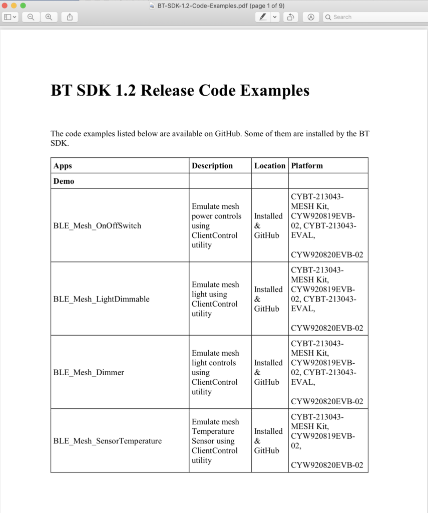
One of my favorite readers, who also happens to be my bosses, bosses boss sent me an email the other day asking about the WS2812 LEDs.  So, I sent him a link to my previous article about PSOC 6 and DMA and WS2812.  He said, “That’s cool and everything… but do you have it in Modus Toolbox”.  Well, you wish is my command.

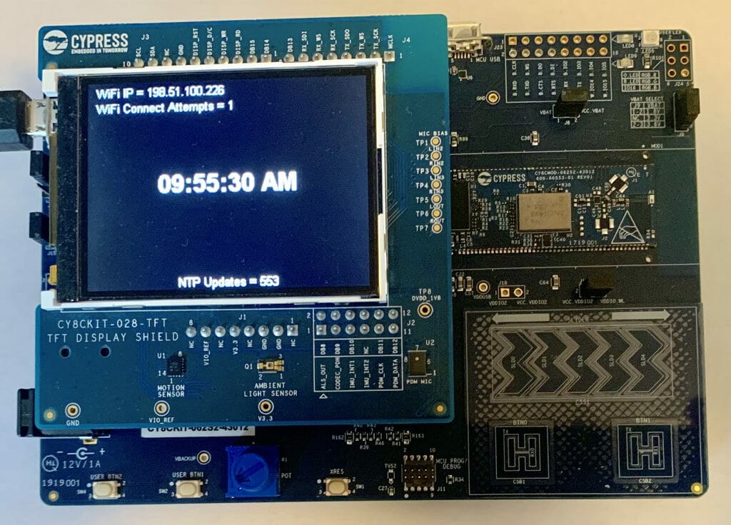
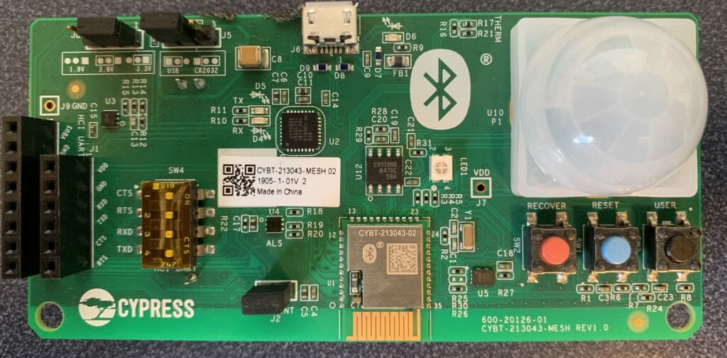
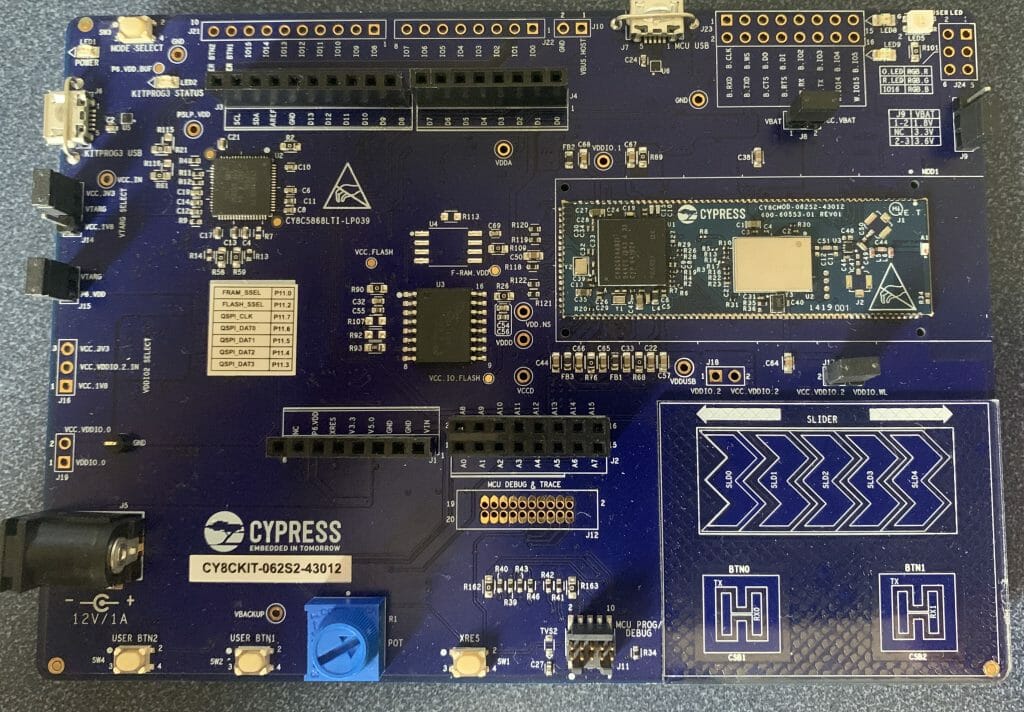
In the original article I wrote directly on the bare metal.  Which is something that I don’t really like, so in this article I will port the original code to use FreeRTOS.  In addition, in the original article I used a CY8CPROTO-062-4343W.  But, look what I found in the mail the other day.  YES! Ronak sent me a prototype of the new Cypress development kit.  Sweet.  Here is a picture.  It has a P6 and a CYW43012 (low power Bluetooth and WiFi).

For this article I will follow these steps:

  1. Make a new project
  2. Add middleware
  3. Configure the retarget i/o, the red LED & Test the configuration
  4. Explain the 2812 Task Architecture
  5. Create ws2812.h
  6. Create ws2812.c
  7. Update main.c to use the public interface of ws2812.h
  8. Rewire to use a level shifter

Finally, I will discuss some other ideas that I have for the project.

Make a New Project

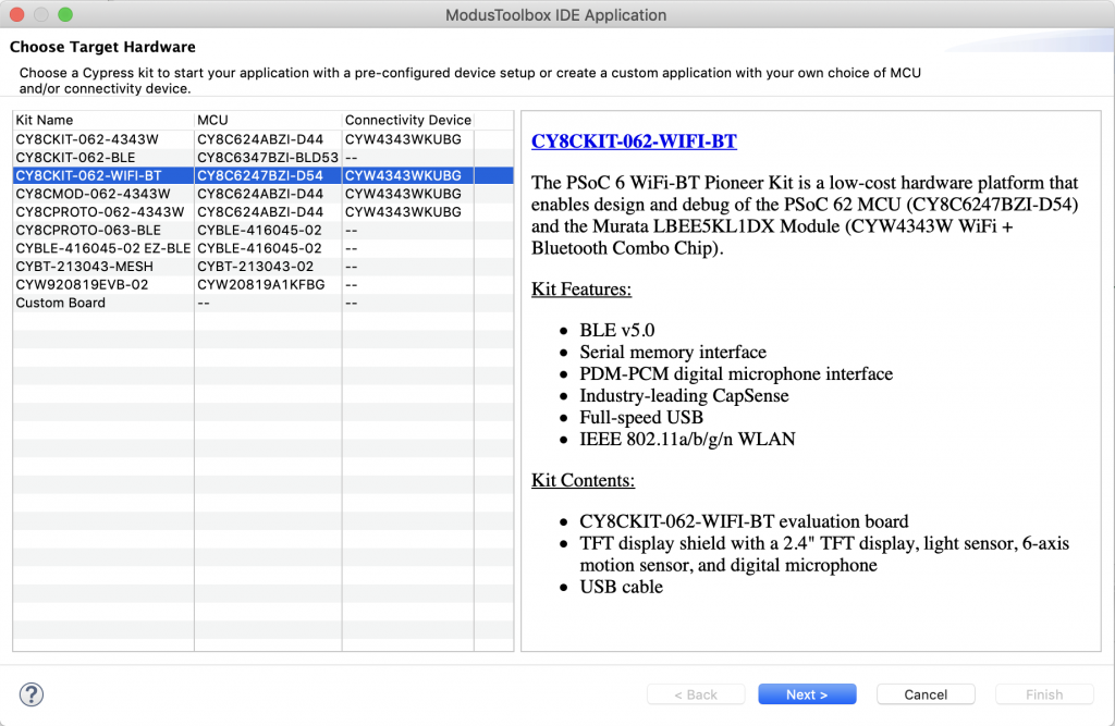
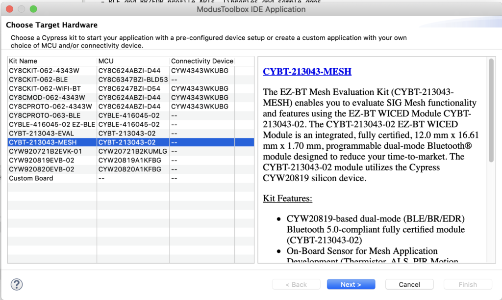
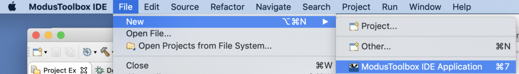
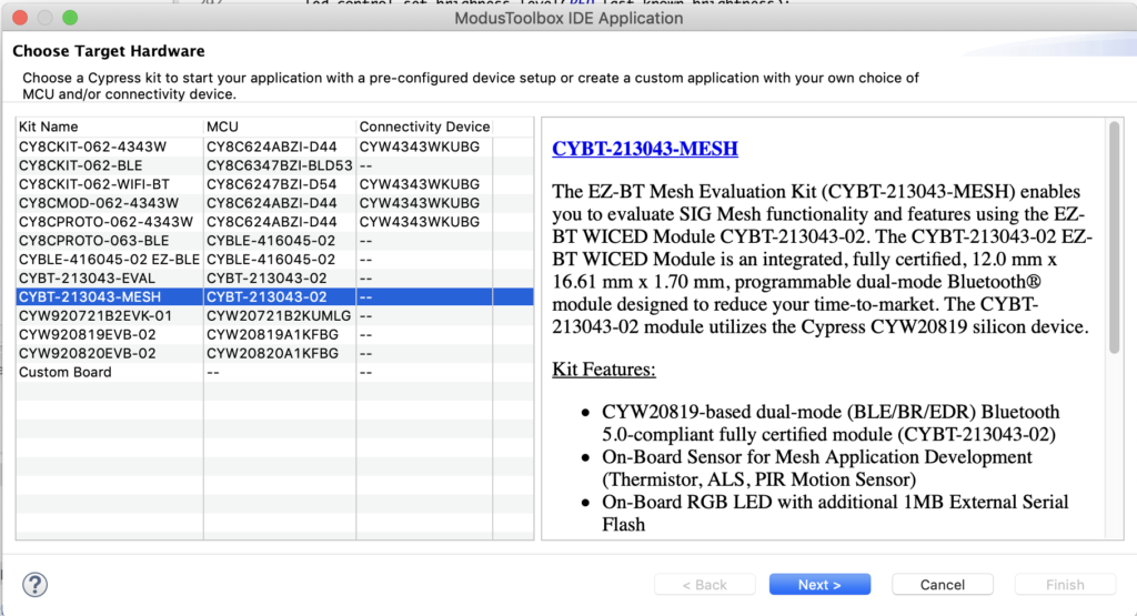
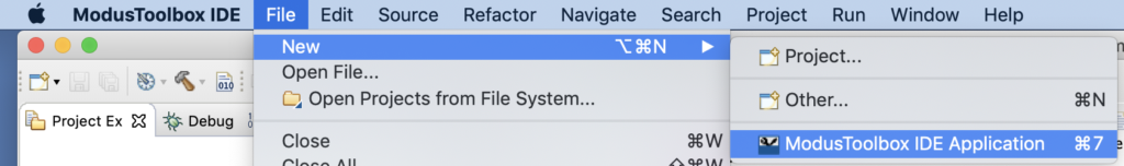
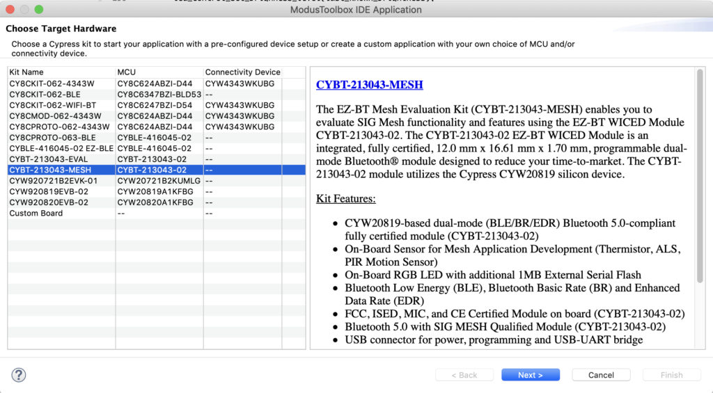
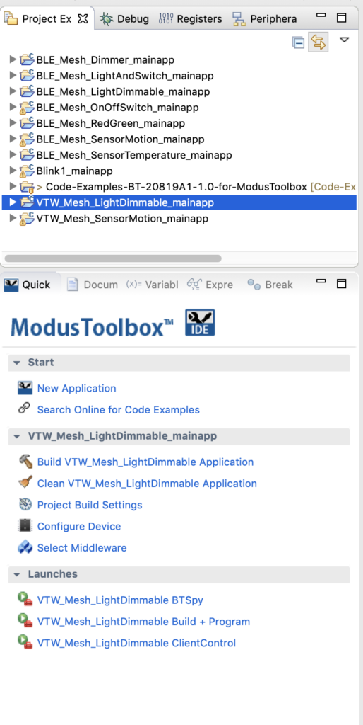
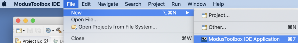
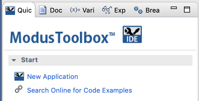
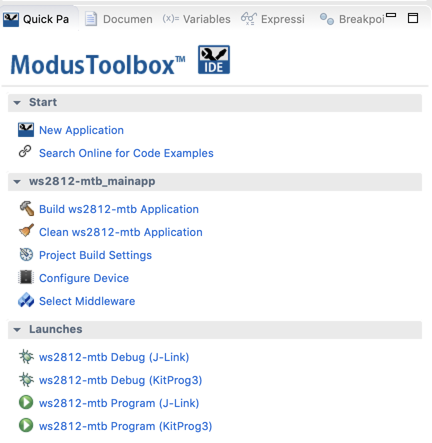
In the quick panel select “New Application”.

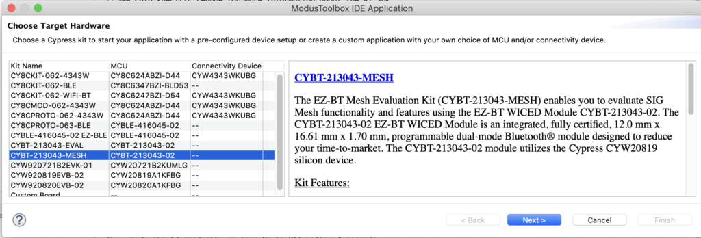
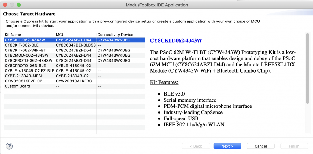
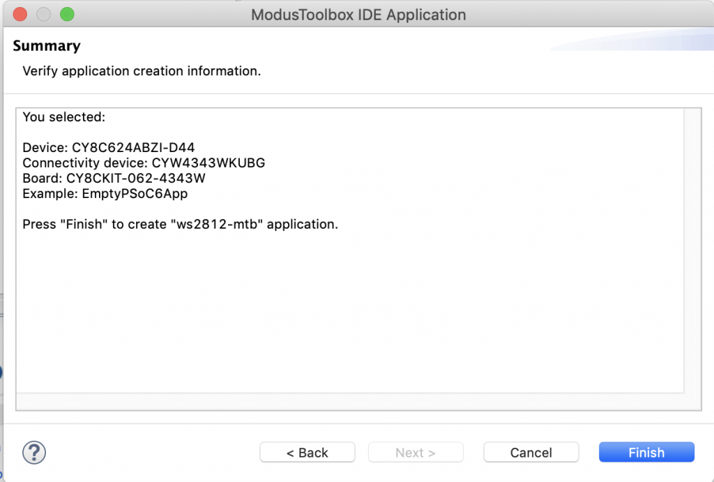
Pick out the “CY8CKIT-062-4343W” which has the same PSoC.  In fact any of the CY8C624ABZI-D44 kits will work.

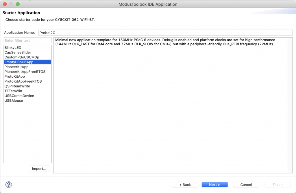
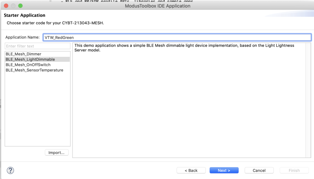
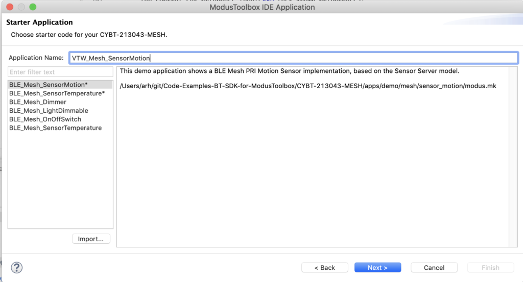
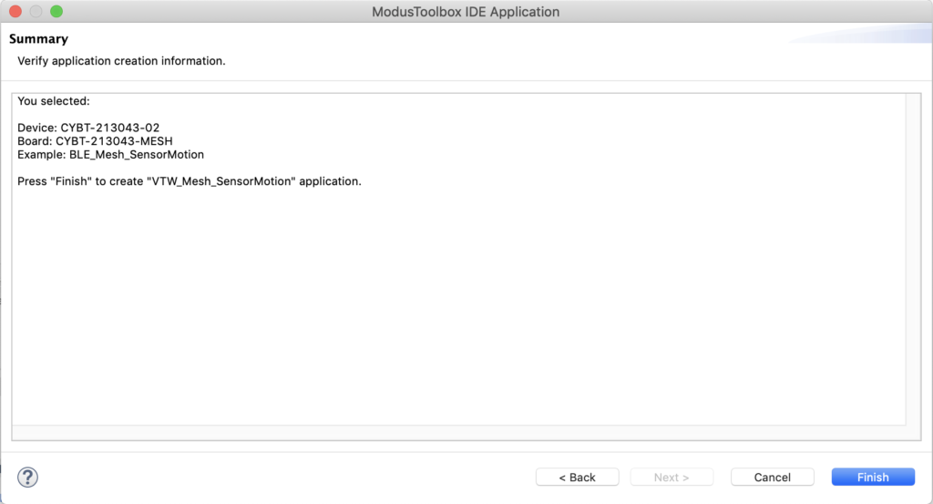
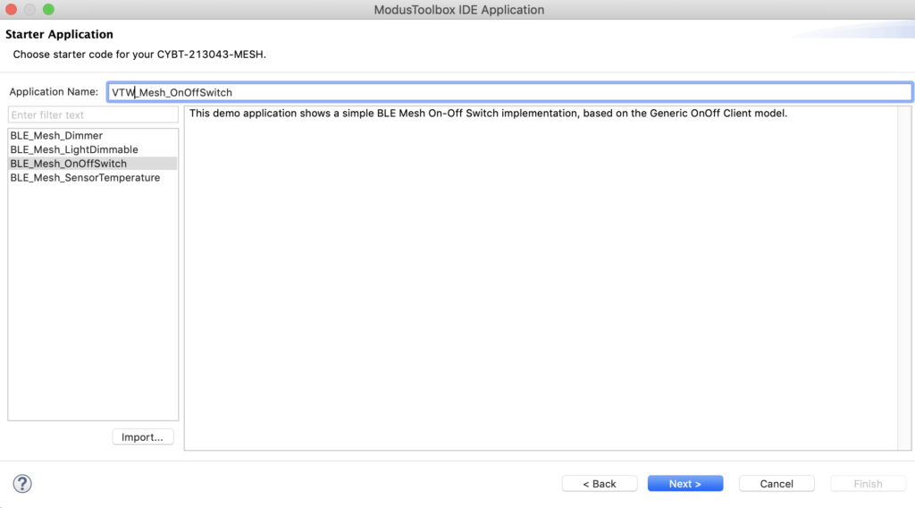
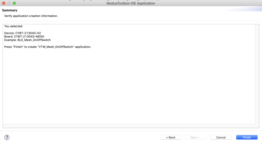
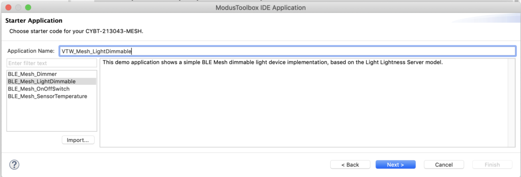
Use the “EmptyPSoC6App” starter project and give it the name “ws2812-mtb”
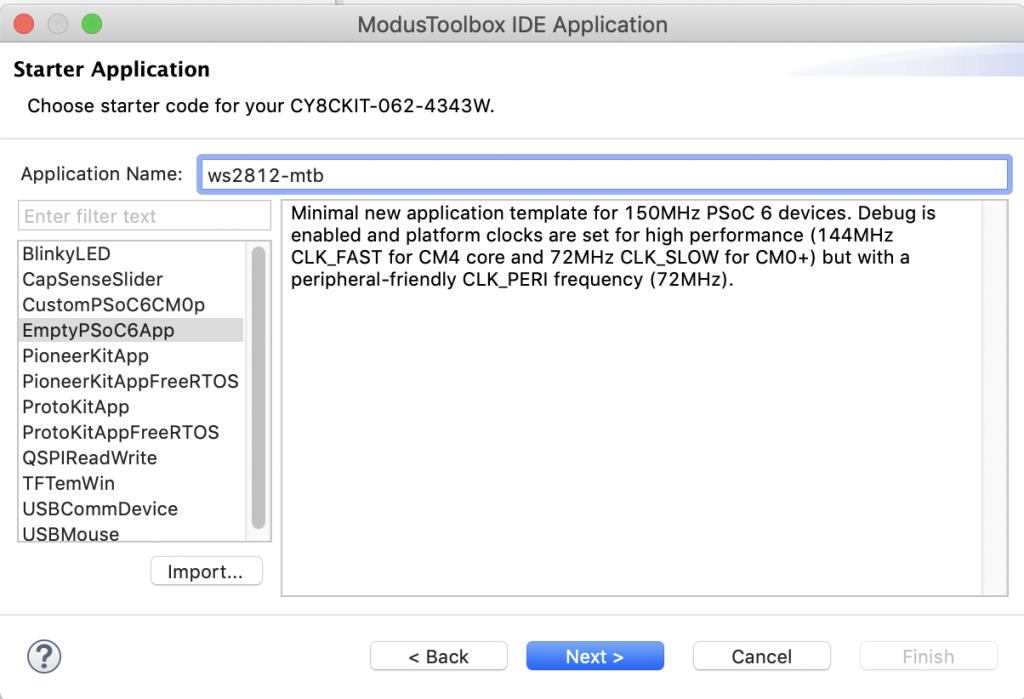
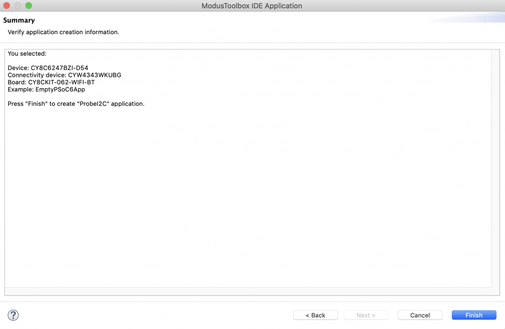
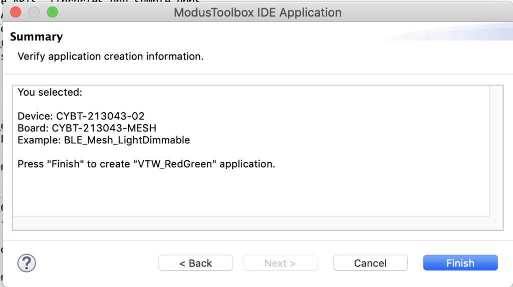
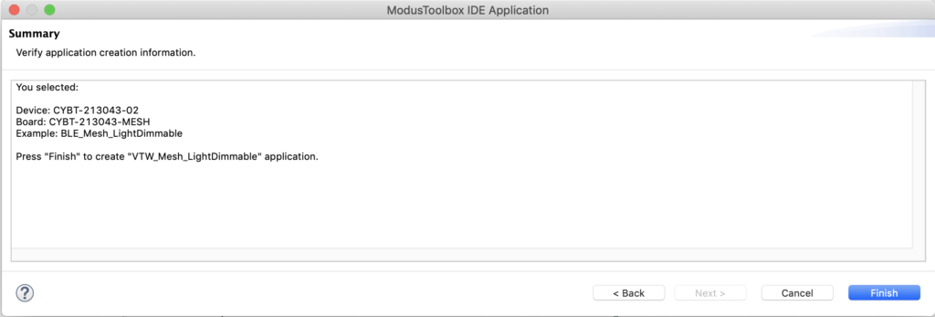
Select “Finish”

Add the Middleware

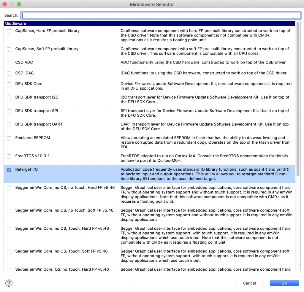
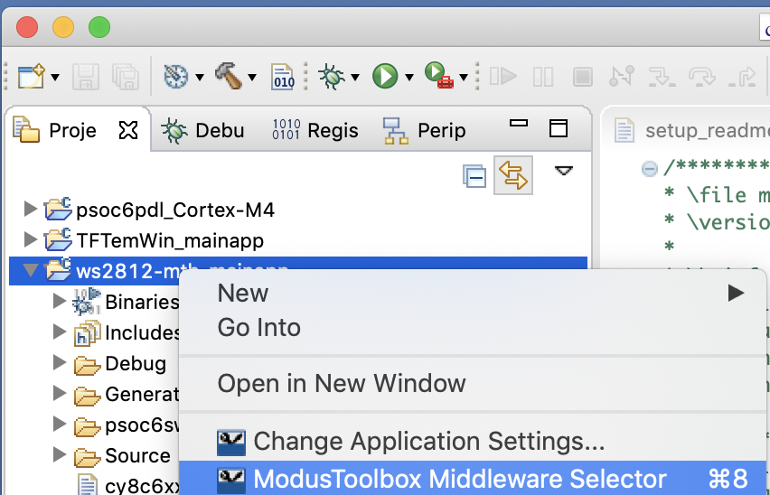
For this project I want to use several pieces of middleware.  To add them, right click on the project and select “ModusToolbox Middleware Selector”

Pick out FreeRTOS, Capsense, and Retarget I/O

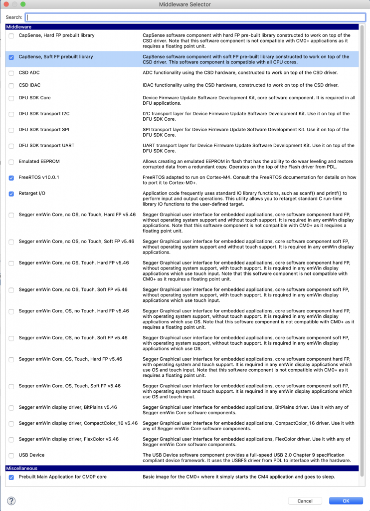
Press OK, which will bring all of the right libraries into your project.

Configure the retarget i/o, the red LED & Test the configuration

Before I get too far down the road I like to test and make sure that the basic stuff is working.  So, I start by configuring the hardware I need for Retarget I/O and the blinking LED.  To do the hardware configuration, select “Configure Device” from the quick panel.

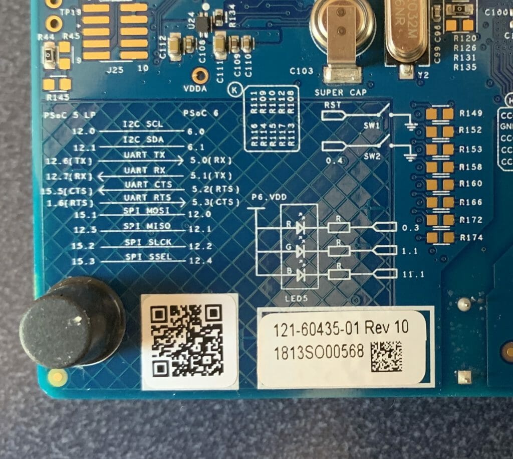
On this board the Red LED is connected to P1[1].  Here is a picture of the very nice label on the back. (notice the engineering sample sticker)

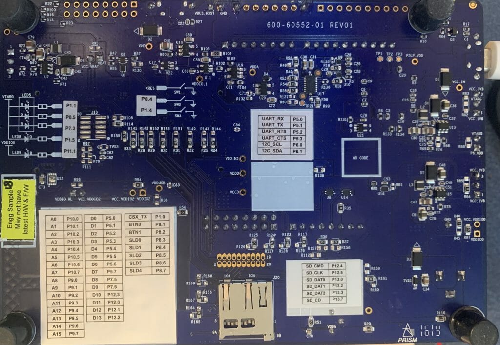
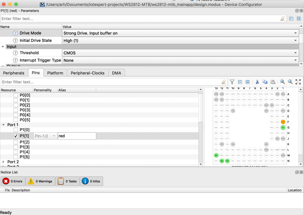
Go to the pins tab, turn on P1[1], give it the name “red” and select the strong drive mode.

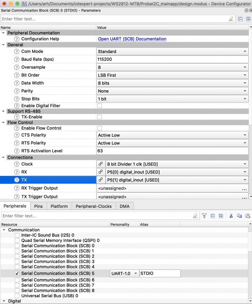
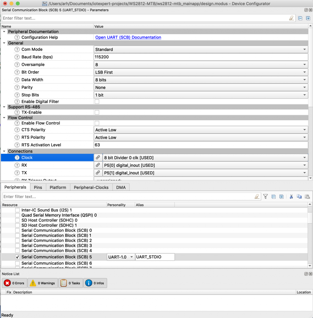
To use the Retarget I/O you need a UART.  Go to the Peripheral tab and turn on “Serial Communication Block (SCB) 5”  Tell it to use P5[0] and P5[1] and the 0th 8-bit clock divider.  Then press save.

Open up studio_user.h and setup the standard i/o to use the correct SCB which we made an alias to called UART_STDIO_HW.  You need to add the include “cycfg.h” so that it can find the alias configuration file.

#include "cy_device_headers.h"
#include "cycfg.h"
/* Must remain uncommented to use this utility */
#define IO_STDOUT_ENABLE
#define IO_STDIN_ENABLE
#define IO_STDOUT_UART      UART_STDIO_HW
#define IO_STDIN_UART       UART_STDIO_HW

and then edit main.c.

  1. Add the include for stdio.h (line 31)
  2. Add the include for FreeRTOS.h (line 32)
  3. Add the include for the task.h (line 33)
  4. Make a context for the UART SCB (line 35)
  5. Write the function for the blinking LED task (line 37-45)
  6. Initialize the SCB as a UART and enable it (lines 53-54)
  7. Print a test message (line 58)
  8. Create the task (line 60)
  9. Start the scheduler (line 61)
#include "cy_device_headers.h"
#include "cycfg.h"
#include <stdio.h>
#include "FreeRTOS.h"
#include "task.h"
cy_stc_scb_uart_context_t UART_STDIO_context;
void ledTask(void *arg)
{
(void)arg;
while(1)
{
Cy_GPIO_Inv(red_PORT,red_PIN);
vTaskDelay(1000);
}
}
int main(void)
{
/* Set up the device based on configurator selections */
init_cycfg_all();
Cy_SCB_UART_Init(UART_STDIO_HW,&UART_STDIO_config,&UART_STDIO_context);
Cy_SCB_UART_Enable(UART_STDIO_HW);
__enable_irq();
printf("Hello world\n");
xTaskCreate(ledTask,"LED Task",100,0,5,0);
vTaskStartScheduler();
}

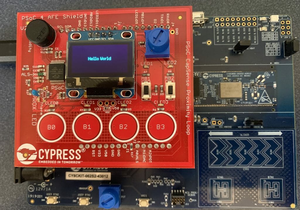
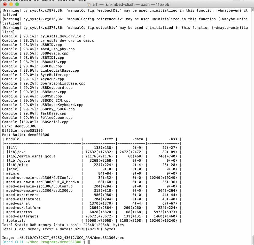
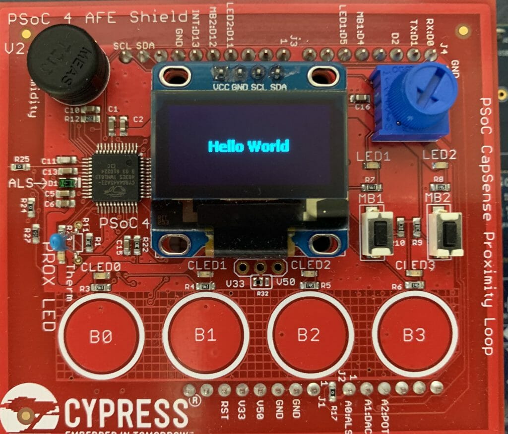
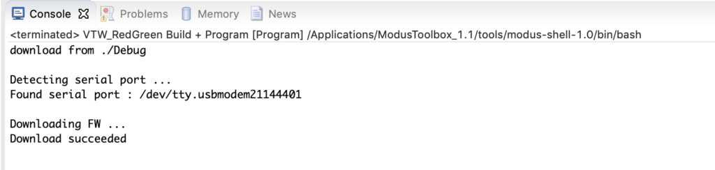
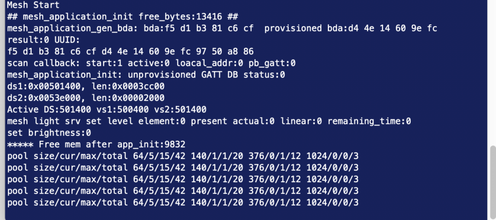
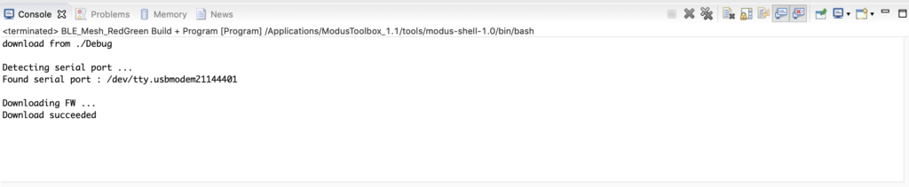
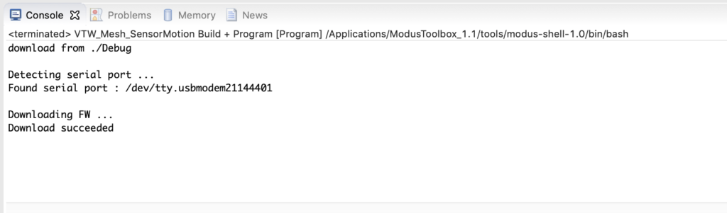
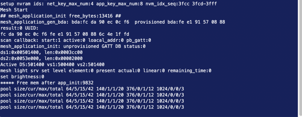
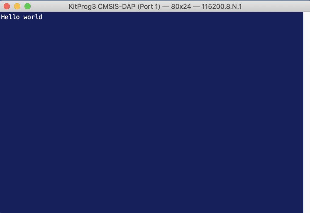
Once you program it you should have a blinking LED + a serial terminal that says “Hello world”

Now that you having a working test jig we will turn ourselves to fixing up the ws2812 driver.

Configure the SPI and DMA

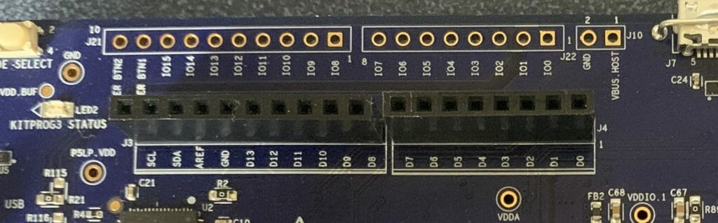
As I discussed in the previous article the I use the SPI to drive the sequence of 110 (for 1’s) or 100 (for 0’s) out to the string of WS2812B LEDs.  The only difference is that this time I will use  SCB0 and P0[2].  Why?  I wanted to save all of the pins on the Arduino  headers for the display.  This lead me to the row of pins on the outside of the header labeled IO0->IO7

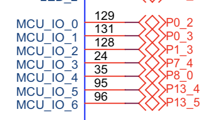
Then I looked at the schematic and found:

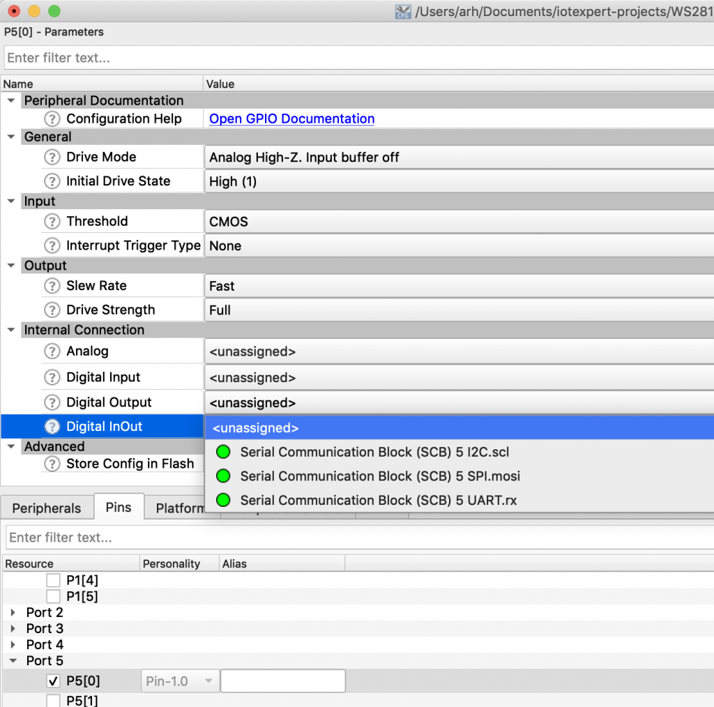
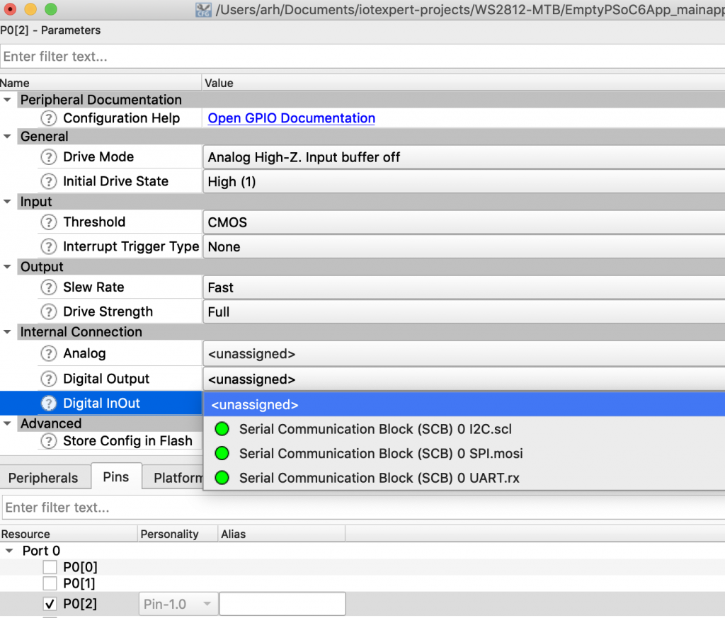
OK I know what the pins are, but how do I know which SCB to attach to?  I started up the device configurator, then went through each of the pins, enabled them, then looked at what the digital inout was attached to by clicking on the dropdown menu.   In the picture below you can see that P0[2] is connected to SCB0 SPI.mosi.

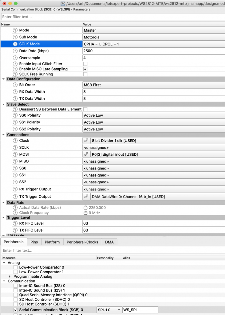
Now I know SCB0. You can read about how I chose the SPI configurations values in the previous article, but for today choose:

  • SCB=SCB0
  • master
  • cpha=1 cpol=1
  • oversample=4
  • clk = clk1
  • MOSI = P0[2]
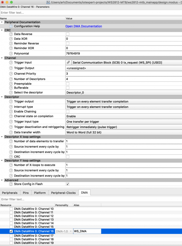
  • Tx trigger = DMA0 Channel 16

The next step is to turn on the DMA block DMA Datawire 0: Channel 16.  I am going to copy the configuration files from the PSoC Creator project, so all I need is the alias for the block

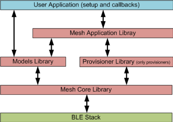
WS2812 Task Architecture

In the original article I have one flat main.c file (actually main_cm4.c)  But, when I look back, I should have used an RTOS (bad Alan).  Basically, I am going to copy the original main_cm4.c and hack it up into a new architecture.  My program will have a task called ws2812Task which will manage the LEDs.  The task will “sit” on a queue that is waiting for the rest of the system to send command messages.  Those messages are in the following format:

typedef enum {
ws2812_cmd_update,            /* no arguments */
ws2812_cmd_autoUpdate,        /* data is a binary true for autoupdate false for no update  */
ws2812_cmd_setRGB,            /* data is pixel number + rgb                                */
ws2812_cmd_setRange,          /* data is 0xFF00 bits for start and 0x00FF bits for y + rgb */
ws2812_cmd_initMixColorRGB,   /* no arguments, turns led string to rgbrgbrgb...                */
}ws2812_cmd_t;
typedef struct {
ws2812_cmd_t cmd;
uint32_t data;
uint8_t red;
uint8_t green;
uint8_t blue;
} ws2812_msg_t;

In addition I will create some public functions which will setup a message and submit it into the queue.  The last piece of the puzzle is that I will have a software timer which will run every 30ms to update the LEDs (if the timer is running)

Create ws2812.h

The public interface to my ws2812Task will reside in a new file called “ws2812.h”.  It is pretty simple

  • Define the number of LEDs
  • Define the enumerated list of legal commands
  • Define the Queue structure ws2812_msg_t (lines
  • 5 helper functions which create a command message and submit it into the queue (lines 15-19)
  • the function prototype for the ws2812Task (line 19)
/*
* ws2812.h
*
*  Created on: Jun 15, 2019
*      Author: arh
*/
#ifndef WS2812_H_
#define WS2812_H_
#include "stdbool.h"
#include "FreeRTOS.h"
#include "queue.h"
#define ws2812_NUM_PIXELS (144)
extern QueueHandle_t ws2812QueueHandle;
typedef enum {
ws2812_cmd_update,            /* no arguments */
ws2812_cmd_autoUpdate,        /* data is a binary true for autoupdate false for no update  */
ws2812_cmd_setRGB,            /* data is pixel number + rgb                                */
ws2812_cmd_setRange,          /* data is 0xFF00 bits for start and 0x00FF bits for y + rgb */
ws2812_cmd_initMixColorRGB,   /* no arguments, turns string to rgbrgbrgb...                */
}ws2812_cmd_t;
typedef struct {
ws2812_cmd_t cmd;
uint32_t data;
uint8_t red;
uint8_t green;
uint8_t blue;
} ws2812_msg_t;
extern QueueHandle_t ws2812QueueHandle;
void ws2812_update(void);
void ws2812_autoUpdate(bool option);
void ws2812_setRGB(int led,uint8_t red, uint8_t green, uint8_t blue);
void ws2812_setRange(int start, int end, uint8_t red,uint8_t green ,uint8_t blue);
void ws2812_initMixColorRGB(void);
void ws2812Task(void *arg);
#endif /* WS2812_H_ */

Create ws2812.c

To build the ws2812.c I start by opening the main_cm4.c from the original project and copying it into the ws2812.c.  At the top I add the includes for ws2812.h and the includes for FreeRTOS.  Next I declare the handle for the Queue and the Timer.  I wanted to have a variable which kept track of the autoUpdate timer being turned on, so I declare a bool.  The rest of the code is from the original program.

#include "ws2812.h"
#include "FreeRTOS.h"
#include "queue.h"
#include "timers.h"
QueueHandle_t ws2812QueueHandle;
TimerHandle_t ws2812TimerHandle;
bool wsAutoUpdateState = false;
#define WS_ZOFFSET (1)
#define WS_ONE3  (0b110<<24)
#define WS_ZERO3 (0b100<<24)
#define WS_SPI_BIT_PER_BIT (3)
#define WS_COLOR_PER_PIXEL (3)
#define WS_BYTES_PER_PIXEL (WS_SPI_BIT_PER_BIT * WS_COLOR_PER_PIXEL)
static uint8_t WS_frameBuffer[ws2812_NUM_PIXELS*WS_BYTES_PER_PIXEL+WS_ZOFFSET];

Next I build the 5 helper functions.  These functions all have exactly the same form,

  • declare a ws2812_msg_t
  • fill it up
  • send it to the queue

Notice that I wait 0 time to try to add to the queue.  What that means is if the queue is full the message will get tossed away.

// These functions are helpers to create the message to send to the ws2812 task.
void ws2812_update(void)
{
ws2812_msg_t msg;
msg.cmd = ws2812_cmd_update;
xQueueSend(ws2812QueueHandle,&msg,0);
}
void ws2812_autoUpdate(bool option)
{
ws2812_msg_t msg;
msg.cmd = ws2812_cmd_autoUpdate;
msg.data = option;
xQueueSend(ws2812QueueHandle,&msg,0);
}
void ws2812_setRGB(int led,uint8_t red, uint8_t green, uint8_t blue)
{
ws2812_msg_t msg;
msg.cmd = ws2812_cmd_setRGB;
msg.red = red;
msg.blue = blue;
msg.green = green;
msg.data = led;
xQueueSend(ws2812QueueHandle,&msg,0);
}
void ws2812_setRange(int start, int end, uint8_t red,uint8_t green ,uint8_t blue)
{
ws2812_msg_t msg;
msg.cmd = ws2812_cmd_setRange;
msg.red = red;
msg.blue = blue;
msg.green = green;
msg.data = start << 16 | end;
xQueueSend(ws2812QueueHandle,&msg,0);
}
void ws2812_initMixColorRGB(void)
{
ws2812_msg_t msg;
msg.cmd = ws2812_cmd_initMixColorRGB;
xQueueSend(ws2812QueueHandle,&msg,0);
}

The next block of code is largely unchanged from the original program, except where I fixed some small differences between the PSoC Creator generated code and the ModusToolbox generated code.

// Function WS_DMAConfiguration
// This function sets up the DMA and the descriptors
#define WS_NUM_DESCRIPTORS (sizeof(WS_frameBuffer) / 256 + 1)
static cy_stc_dma_descriptor_t WSDescriptors[WS_NUM_DESCRIPTORS];
static void WS_DMAConfigure(void)
{
// I copies this structure from the PSoC Creator Component configuration
// in generated source
const cy_stc_dma_descriptor_config_t WS_DMA_Descriptors_config =
{
.retrigger       = CY_DMA_RETRIG_IM,
.interruptType   = CY_DMA_DESCR_CHAIN,
.triggerOutType  = CY_DMA_1ELEMENT,
.channelState    = CY_DMA_CHANNEL_ENABLED,
.triggerInType   = CY_DMA_1ELEMENT,
.dataSize        = CY_DMA_BYTE,
.srcTransferSize = CY_DMA_TRANSFER_SIZE_DATA,
.dstTransferSize = CY_DMA_TRANSFER_SIZE_WORD,
.descriptorType  = CY_DMA_1D_TRANSFER,
.srcAddress      = NULL,
.dstAddress      = NULL,
.srcXincrement   = 1L,
.dstXincrement   = 0L,
.xCount          = 256UL,
.srcYincrement   = 0L,
.dstYincrement   = 0L,
.yCount          = 1UL,
.nextDescriptor  = 0
};
for(unsigned int i=0;i<WS_NUM_DESCRIPTORS;i++)
{
Cy_DMA_Descriptor_Init(&WSDescriptors[i], &WS_DMA_Descriptors_config);
Cy_DMA_Descriptor_SetSrcAddress(&WSDescriptors[i], (uint8_t *)&WS_frameBuffer[i*256]);
Cy_DMA_Descriptor_SetDstAddress(&WSDescriptors[i], (void *)&WS_SPI_HW->TX_FIFO_WR);
Cy_DMA_Descriptor_SetXloopDataCount(&WSDescriptors[i],256); // the last
Cy_DMA_Descriptor_SetNextDescriptor(&WSDescriptors[i],&WSDescriptors[i+1]);
}
// The last one needs a bit of change
Cy_DMA_Descriptor_SetXloopDataCount(&WSDescriptors[WS_NUM_DESCRIPTORS-1],sizeof(WS_frameBuffer)-256*(WS_NUM_DESCRIPTORS-1)); // the last
Cy_DMA_Descriptor_SetNextDescriptor(&WSDescriptors[WS_NUM_DESCRIPTORS-1],0);
Cy_DMA_Descriptor_SetChannelState(&WSDescriptors[WS_NUM_DESCRIPTORS-1],CY_DMA_CHANNEL_DISABLED);
Cy_DMA_Enable(WS_DMA_HW);
}
// Function: WS_DMATrigger
// This function sets up the channel... then enables it to dump the frameBuffer to pixels
void WS_DMATrigger()
{
cy_stc_dma_channel_config_t channelConfig;
channelConfig.descriptor  = &WSDescriptors[0];
channelConfig.preemptable = false;
channelConfig.priority    = 3;
channelConfig.enable      = false;
Cy_DMA_Channel_Init(WS_DMA_HW, WS_DMA_CHANNEL, &channelConfig);
Cy_DMA_Channel_Enable(WS_DMA_HW,WS_DMA_CHANNEL);
}

The next block of code is just a function which the autoupdate timer can call to trigger the DMA to update the stripe of LEDs.

// This function is called by the software timer which is used to autoupdate the LEDs
// It checks to make sure that the DMA is done... if not it doesnt do anything
void ws2812CallbackFunction( TimerHandle_t xTimer )
{
if((Cy_DMA_Channel_GetStatus(WS_DMA_HW,WS_DMA_CHANNEL) & CY_DMA_INTR_CAUSE_COMPLETION))
{
WS_DMATrigger();
}
}

From lines 156-372 I use the original functions to implement the frame buffer for WS2812 (you can read about that in the original article).  I am not including these functions here.

The final block of code is the actual task which manages the ws2812 led string.  On lines 379->395 it sets up the SPI, DMA, Queue and Timer.   Then it goes into the infinite loop waiting for command messages.  The message loop just looks at the command, the calls the correct helper function.

void ws2812Task(void *arg)
{
ws2812_msg_t msg;
cy_stc_scb_spi_context_t WS_SPI_context;
vTaskDelay(100);
printf("Starting ws2812 task\n");
WS_runTest();
WS_frameBuffer[0] = 0x00;
WS_setRange(0,ws2812_NUM_PIXELS-1,0,0,0); // Initialize everything OFF
Cy_SCB_SPI_Init(WS_SPI_HW, &WS_SPI_config, &WS_SPI_context);
Cy_SCB_SPI_Enable(WS_SPI_HW);
WS_DMAConfigure();
// This queue handles messages from the keyboard
ws2812QueueHandle = xQueueCreate( 10,sizeof(ws2812_msg_t));
// This timer calls the update function every 30ms if it is turned on.
ws2812TimerHandle = xTimerCreate("ws2812 timer",pdMS_TO_TICKS(30),pdTRUE,0,ws2812CallbackFunction );
while(1)
{
xQueueReceive(ws2812QueueHandle,&msg,0xFFFFFFFF);
switch(msg.cmd)
{
case ws2812_cmd_update:
if(!wsAutoUpdateState)
{
WS_DMATrigger();
}
break;
case ws2812_cmd_autoUpdate:
if(wsAutoUpdateState && msg.data == false)
{
xTimerStop(ws2812TimerHandle,0);
}
else if(!wsAutoUpdateState && msg.data == true)
{
xTimerStart(ws2812TimerHandle,0);
}
wsAutoUpdateState = msg.data;
break;
case ws2812_cmd_setRGB:
WS_setRGB( msg.data,msg.red,msg.green ,msg.blue);
break;
case ws2812_cmd_setRange:
WS_setRange(msg.data>>16 & 0xFFFF, msg.data&0xFFFF, msg.red,msg.green ,msg.blue);
break;
case ws2812_cmd_initMixColorRGB:
WS_initMixColorRGB();
break;
}
}
}

Update main.c to use the Public Interface of ws2812.h

Initially when I did this, I just updated main.c.  But, after thinking about it a little bit I decided that it was better to create a uartTask.h and uartTask.c to make the keyboard processing a bit more self contained.  Starting with the public interface to uartTask.h.  This file simply declares the function prototype for the uartTask.

/*
* uartTask.h
*
*  Created on: Jun 16, 2019
*      Author: arh
*/
#ifndef SOURCE_UARTTASK_H_
#define SOURCE_UARTTASK_H_
void uartTask(void *arg);
#endif /* SOURCE_UARTTASK_H_ */

I do not like to poll!  Ever!  That is the point of an RTOS.  Don’t poll if you can at all get away from it.  To avoid polling I set up the SCB UART to give an interrupt when it receives a character.  In the ISR I then turn off the interrupts and increment a semaphore.  In the main body of the task I “sit” on the semaphore and wait for it to be incremented.  Once it is incremented, I read and process characters until there are no more.  Then turn the interrupts back on.

The uartTask.c has three sections

  • The header where I do all of the includes and define the semaphore
  • The ISR where I turn off the interrupts and set the semaphore
  • The main task.

First, the beginning of the file just does the normal includes.  It also declares a context for the UART and it declares a handle for the semaphore.

/*
* uartTask.c
*
*  Created on: Jun 16, 2019
*      Author: arh
*/
#include <stdio.h>
#include "ws2812.h"
#include "FreeRTOS.h"
#include "task.h"
#include "semphr.h"
#include "cy_device_headers.h"
#include "cycfg.h"
#include "cy_pdl.h"
cy_stc_scb_uart_context_t UART_STDIO_context;
SemaphoreHandle_t UART_STDIO_SemaphoreHandle;

The ISR simply turns off the interrupt mask so that no interrupts happen until the Rx fifo is clear (line 24).  Then clears the interrupt source (meaning tells the SCB to turn off the interrupt) so that it doesn’t just re-pend the interrupt (line 25).  Then it increments the semaphore and does the normal FreeRTOS context switch if needed.

void UART_Isr(void)
{
// Disable & clear the interrupt
Cy_SCB_SetRxInterruptMask(UART_STDIO_HW,0);
Cy_SCB_ClearRxInterrupt(UART_STDIO_HW, CY_SCB_RX_INTR_NOT_EMPTY);
static BaseType_t xHigherPriorityTaskWoken;
xHigherPriorityTaskWoken = pdFALSE;
xSemaphoreGiveFromISR( UART_STDIO_SemaphoreHandle, &xHigherPriorityTaskWoken );
portYIELD_FROM_ISR( xHigherPriorityTaskWoken );
}

The uartTask function has several parts

  • Initialize the semaphore (line 36)
  • Initialize the SCB and Interrupt (lines 38-49)
  • Waits for the semaphore to be set (line 55)
  • Loops until the Rx FIFO is empty (line 57)
  • Reads a character and does correct operation with a giant switch (59-127)
  • When all the characters are done being read (aka the Rx FIFO is empty) turn back on the interrupt (line 129)
void uartTask(void *arg)
{
UART_STDIO_SemaphoreHandle = xSemaphoreCreateCounting( 0xFFFF,0); // Semaphore counts unprocessed key presses
Cy_SCB_UART_Init(UART_STDIO_HW,&UART_STDIO_config,&UART_STDIO_context);
cy_stc_sysint_t uartIntrConfig =
{
.intrSrc      = UART_STDIO_IRQ,
.intrPriority = 7,
};
(void) Cy_SysInt_Init(&uartIntrConfig, &UART_Isr);
NVIC_EnableIRQ(UART_STDIO_IRQ);
Cy_SCB_SetRxInterruptMask(UART_STDIO_HW,CY_SCB_RX_INTR_NOT_EMPTY);
setvbuf( stdin, NULL, _IONBF, 0 ); // Turn off Input buffering on STDIO
Cy_SCB_UART_Enable(UART_STDIO_HW);
printf("Starting UART Task\n");
for(;;)
{
xSemaphoreTake( UART_STDIO_SemaphoreHandle, 0xFFFFFFFF); // Wait for a semaphore
while(Cy_SCB_UART_GetNumInRxFifo(UART_STDIO_HW))
{
char c=getchar();
switch(c)
{
case 'u':
printf("Enable auto DMA updating\n");
ws2812_autoUpdate(true);
break;
case 'U':
printf("Disable auto DMA updating\n");
ws2812_autoUpdate(false);
break;
case 't':
printf("Update LEDs\n");
ws2812_update();
break;
case 'r':
ws2812_setRGB(0,0xFF,0,0);
printf("Set LED0 Red\n");
break;
case 'g':
ws2812_setRGB(0,0,0xFF,0);
printf("Set LED0 Green\n");
break;
case 'O':
ws2812_setRange(0,ws2812_NUM_PIXELS-1,0,0,0);
printf("Turn off all LEDs\n");
break;
case 'o':
ws2812_setRange(0,ws2812_NUM_PIXELS-1,0xFF,0xFF,0xFF);
printf("Turn on all LEDs\n");
break;
case 'b':
ws2812_setRGB(0,0,0,0xFF);
printf("Set LED0 Blue\n");
break;
case 'R':
ws2812_setRange(0,ws2812_NUM_PIXELS-1,0x80,0,0);
printf("Turn on all LEDs RED\n");
break;
case 'G':
ws2812_setRange(0,ws2812_NUM_PIXELS-1,0,0x80,0);
printf("Turn on all LEDs Green\n");
break;
case 'B':
ws2812_setRange(0,ws2812_NUM_PIXELS-1,0,0,0x80);
printf("Turn on all LEDs Blue\n");
break;
case 'a':
ws2812_initMixColorRGB();
printf("Turn on all LEDs RGB Pattern\n");
break;
case '?':
printf("u\tEnable Auto Update of LEDs\n");
printf("U\tDisable Auto Update of LEDs\n");
printf("t\tTrigger the DMA\n");
printf("r\tSet the first pixel Red\n");
printf("g\tSet the first pixel Green\n");
printf("b\tSet the first pixel Blue\n");
printf("O\tTurn off all of the pixels\n");
printf("o\tSet the pixels to white full on\n");
printf("R\tSet all of the pixels to Red\n");
printf("G\tSet all of the pixels to Green\n");
printf("B\tSet all of the pixels to Blue\n");
printf("a\tSet pixels to repeating RGBRGB\n");
printf("?\tHelp\n");
break;
}
}
// turn the rx fifo interrupt back on
Cy_SCB_SetRxInterruptMask(UART_STDIO_HW,CY_SCB_RX_INTR_NOT_EMPTY); // Turn on interrupts for Rx buffer
}
}

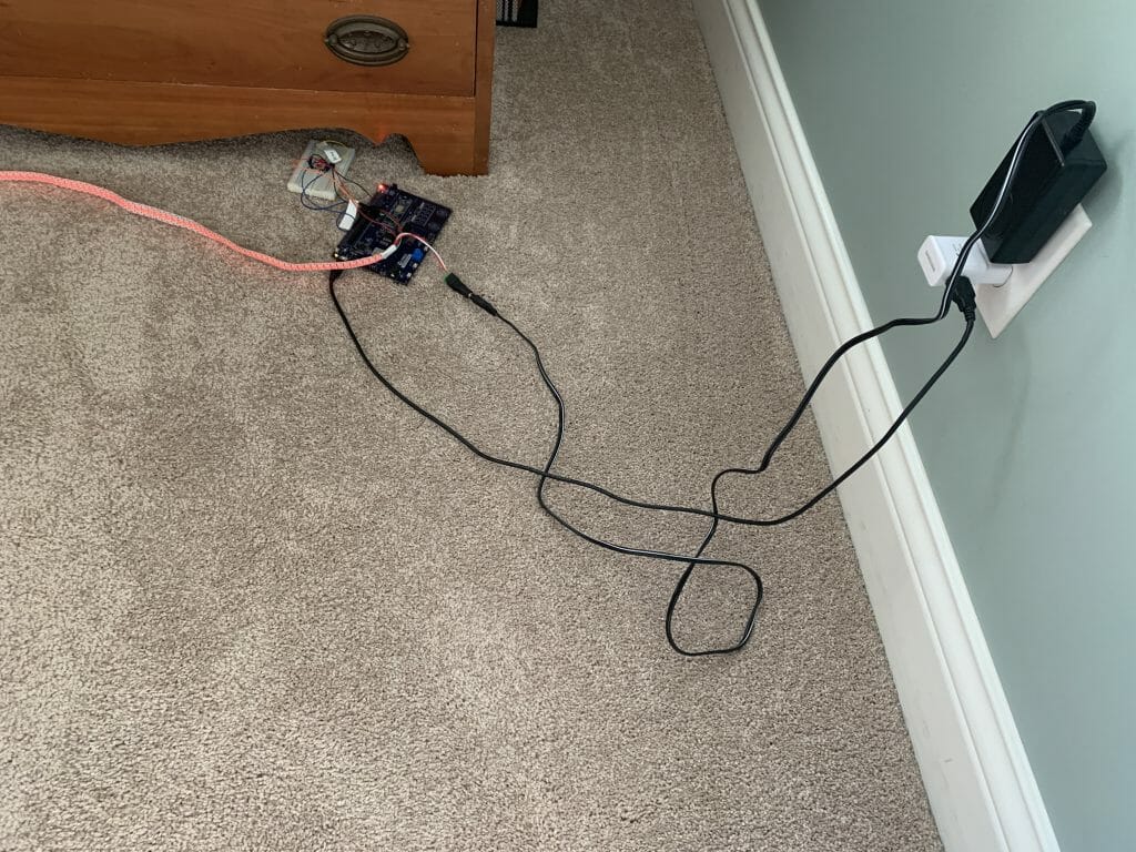
Rewire to Use a Level Shifter

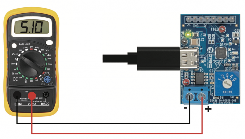
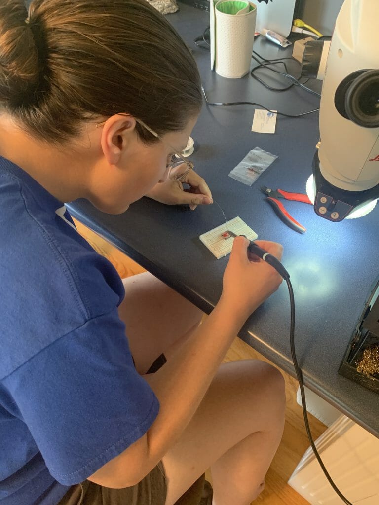
At the end of the previous article I said “I’m Lucky it Works. The last thing to observe in all of this is that I am driving the LED string with a 5V wall wart. And according to the datasheet VIH is 0x7 * VDD = 3.5V … and I am driving it with a PSoC 6 with 3.3V. Oh well.”  This time I am not so lucky.  I am not totally sure why (probably because I used a different power supply) but it doesn’t work.  So I put my lab assistant to work putting together a level shifter that I got from SparkFun.  For those of you long time readers, you will say, “Hey that isn’t Nicholas”.  Well, it is my other lab assistant, Anna.  And she is just as good at soldering!

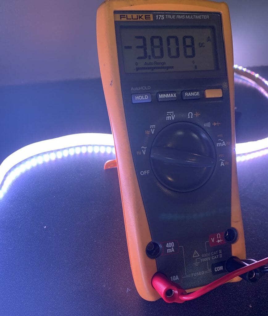
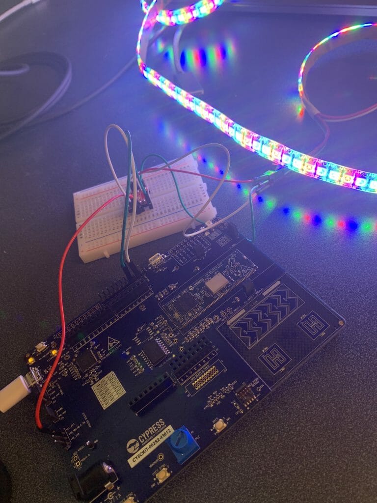
Now when I try it, everything works!

What is next?

As I was working on the project, I thought of several things that I would like to add to the project including:

  • A random color / blinking mode
  • A CapSense button and slider
  • The TFT display
  • Ability to handle multiple strips of LEDs

But for now, all that stuff is for another day.

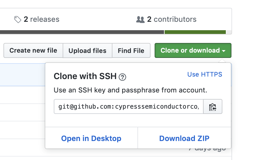
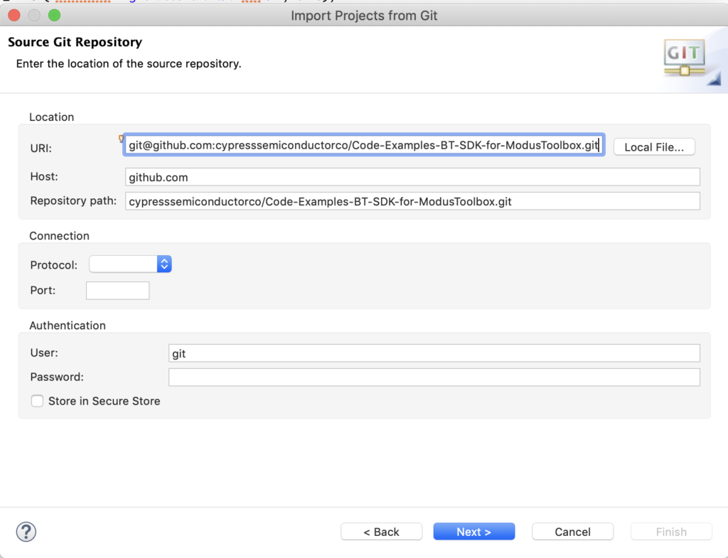
You can find all of this code at my github site. git@github.com:iotexpert/WS2812-MTB.git

Mouser Bluetooth Mesh: L7 Modifying the Dimmable Light Code to Add Another Light Element

How To Design With Bluetooth Mesh


You can "git" a workspace will all of these files at https://github.com/iotexpert/MouserVTWBluetoothMesh or git@github.com:iotexpert/MouserVTWBluetoothMesh.git

Summary

In this project I will create a Bluetooth Mesh Node that has two Light Lightness Server elements, one to control the red LED and one to control the Green LED.  The purpose is to show an example adding elements to a node.

I will start with the BLE_Mesh_LightDimmable and then modify it to add the ability to control the Green LED as well.

To implement this lesson I will follow these steps:

  1. Make New Application with BLE_Mesh_LightDimmable Template
  2. Program it to make sure that things are still working
  3. Modify led_control.h to handle two LEDs
  4. Modify led_control.c to handle two LEDs
  5. Modify light_dimmable.c to update the Bluetooth Mesh Configuration
  6. Test

Make New Project with BLE_Mesh_LightDimmable Template

Use File->New->ModusToobox IDE Application

Pick the “CYBT-213043-MESH”

Choose “BLE_Mesh_LightDimmable” and name your project “VTW_RedGreen”

Click “Finish”

Program it to make sure that things are still working by clicking “Launches -> VTW_RedGreen Build + Program”

After it is downloaded you can see that it boots.

Press “Start Scan”.  After a while you will see that it found the device.

Now press “Provision and configure”

Modify led_control.h

The files led_control.h and .c are used to manage the LED.  I will extend the led_control_set_brightness_level by adding the ability to control two LEDs – a Red and a Green

typedef enum {
RED,
GREEN,
} led_control_t;
void led_control_init(void);
void led_control_set_brighness_level(led_control_t whichLED, uint8_t brightness_level);

Modify led_control.c

Now I need to hook up a PWM to the Green LED.  I will use PWM1 (notice that I also change the PWM_CHANNEL to _RED and _GREEN)

#define PWM_CHANNEL_RED           PWM0
#define PWM_CHANNEL_GREEN         PWM1

The led_control_init function is used to setup the hardware.  Specifically to configure the two PWMs to be attached to the correct pins.

void led_control_init(void)
{
pwm_config_t pwm_config;
/* configure PWM */
wiced_hal_gpio_select_function(WICED_GPIO_PIN_LED_2, WICED_PWM0);
wiced_hal_gpio_select_function(WICED_GPIO_PIN_LED_3, WICED_PWM1);
wiced_hal_aclk_enable(PWM_INP_CLK_IN_HZ, ACLK1, ACLK_FREQ_24_MHZ);
wiced_hal_pwm_get_params(PWM_INP_CLK_IN_HZ, 0, PWM_FREQ_IN_HZ, &pwm_config);
wiced_hal_pwm_start(PWM_CHANNEL_RED, PMU_CLK, pwm_config.toggle_count, pwm_config.init_count, 1);
wiced_hal_pwm_start(PWM_CHANNEL_GREEN, PMU_CLK, pwm_config.toggle_count, pwm_config.init_count, 1);
}

Finally, I modify the …set_brightness… function to handle Red and Green.

void led_control_set_brighness_level(led_control_t whichLED, uint8_t brightness_level)
{
pwm_config_t pwm_config;
WICED_BT_TRACE("set brightness:%d\n", brightness_level);
// ToDo.  For some reason, setting brightness to 100% does not work well on 20719B1 platform. For now just use 99% instead of 100.
if (brightness_level == 100)
brightness_level = 99;
wiced_hal_pwm_get_params(PWM_INP_CLK_IN_HZ, brightness_level, PWM_FREQ_IN_HZ, &pwm_config);
switch(whichLED)
{
case RED:
wiced_hal_pwm_change_values(PWM_CHANNEL_RED, pwm_config.toggle_count, pwm_config.init_count);
break;
case GREEN:
wiced_hal_pwm_change_values(PWM_CHANNEL_GREEN, pwm_config.toggle_count, pwm_config.init_count);
break;
}
}

Modify light_dimmable.c

Now I need to add a new element to the mesh_elements array.  Before I can do that, it need to create new element array called “mesh_element2_models” with the model that I need.  Notice that I also change the original code to have _RED

wiced_bt_mesh_core_config_model_t   mesh_element1_models[] =
{
WICED_BT_MESH_DEVICE,
WICED_BT_MESH_MODEL_USER_PROPERTY_SERVER,
WICED_BT_MESH_MODEL_LIGHT_LIGHTNESS_SERVER,
};
#define MESH_APP_NUM_MODELS_RED  (sizeof(mesh_element1_models) / sizeof(wiced_bt_mesh_core_config_model_t))
wiced_bt_mesh_core_config_property_t mesh_element1_properties[] =
{
{
.id          = WICED_BT_MESH_PROPERTY_DEVICE_FIRMWARE_REVISION,
.type        = WICED_BT_MESH_PROPERTY_TYPE_USER,
.user_access = WICED_BT_MESH_PROPERTY_ID_READABLE,
.max_len     = WICED_BT_MESH_PROPERTY_LEN_DEVICE_FIRMWARE_REVISION,
.value       = mesh_prop_fw_version
},
};
#define MESH_APP_NUM_PROPERTIES (sizeof(mesh_element1_properties) / sizeof(wiced_bt_mesh_core_config_property_t))
wiced_bt_mesh_core_config_model_t   mesh_element2_models[] =
{
WICED_BT_MESH_MODEL_LIGHT_LIGHTNESS_SERVER,
};
#define MESH_APP_NUM_MODELS_GREEN  (sizeof(mesh_element2_models) / sizeof(wiced_bt_mesh_core_config_model_t))
#define MESH_LIGHT_LIGHTNESS_SERVER_ELEMENT_INDEX_RED   0
#define MESH_LIGHT_LIGHTNESS_SERVER_ELEMENT_INDEX_GREEN   1
wiced_bt_mesh_core_config_element_t mesh_elements[] =
{
{
.location = MESH_ELEM_LOC_MAIN,                                 // location description as defined in the GATT Bluetooth Namespace Descriptors section of the Bluetooth SIG Assigned Numbers
.default_transition_time = MESH_DEFAULT_TRANSITION_TIME_IN_MS,  // Default transition time for models of the element in milliseconds
.onpowerup_state = WICED_BT_MESH_ON_POWER_UP_STATE_RESTORE,     // Default element behavior on power up
.default_level = 0,                                             // Default value of the variable controlled on this element (for example power, lightness, temperature, hue...)
.range_min = 1,                                                 // Minimum value of the variable controlled on this element (for example power, lightness, temperature, hue...)
.range_max = 0xffff,                                            // Maximum value of the variable controlled on this element (for example power, lightness, temperature, hue...)
.move_rollover = 0,                                             // If true when level gets to range_max during move operation, it switches to min, otherwise move stops.
.properties_num = MESH_APP_NUM_PROPERTIES,                      // Number of properties in the array models
.properties = mesh_element1_properties,                         // Array of properties in the element.
.sensors_num = 0,                                               // Number of sensors in the sensor array
.sensors = NULL,                                                // Array of sensors of that element
.models_num = MESH_APP_NUM_MODELS_RED,                          // Number of models in the array models
.models = mesh_element1_models,                                 // Array of models located in that element. Model data is defined by structure wiced_bt_mesh_core_config_model_t
},
{
.location = MESH_ELEM_LOC_MAIN,                                 // location description as defined in the GATT Bluetooth Namespace Descriptors section of the Bluetooth SIG Assigned Numbers
.default_transition_time = MESH_DEFAULT_TRANSITION_TIME_IN_MS,  // Default transition time for models of the element in milliseconds
.onpowerup_state = WICED_BT_MESH_ON_POWER_UP_STATE_RESTORE,     // Default element behavior on power up
.default_level = 0,                                             // Default value of the variable controlled on this element (for example power, lightness, temperature, hue...)
.range_min = 1,                                                 // Minimum value of the variable controlled on this element (for example power, lightness, temperature, hue...)
.range_max = 0xffff,                                            // Maximum value of the variable controlled on this element (for example power, lightness, temperature, hue...)
.move_rollover = 0,                                             // If true when level gets to range_max during move operation, it switches to min, otherwise move stops.
.properties_num = 0,                                            // Number of properties in the array models
.properties = NULL,                                             // Array of properties in the element.
.sensors_num = 0,                                               // Number of sensors in the sensor array
.sensors = NULL,                                                // Array of sensors of that element
.models_num = MESH_APP_NUM_MODELS_GREEN,                              // Number of models in the array models
.models = mesh_element2_models,                                 // Array of models located in that element. Model data is defined by structure wiced_bt_mesh_core_config_model_t
},
};

In the mesh_app_init function you need to initialize the new light lightness server model. We will use the same message handler for both light lightness server models.

    wiced_bt_mesh_model_light_lightness_server_init(MESH_LIGHT_LIGHTNESS_SERVER_ELEMENT_INDEX_GREEN, mesh_app_message_handler, is_provisioned);

Search and replace all of the “led_control_set_brighness_level(attention_brightness);” to be “led_control_set_brighness_level(RED,attention_brightness);”

The last step is to update the mesh_app_process_set_level callback to handle the two cases.

/*
* Command from the level client is received to set the new level
*/
void mesh_app_process_set_level(uint8_t element_idx, wiced_bt_mesh_light_lightness_status_t *p_status)
{
WICED_BT_TRACE("mesh light srv set level element:%d present actual:%d linear:%d remaining_time:%d\n",
element_idx, p_status->lightness_actual_present, p_status->lightness_linear_present, p_status->remaining_time);
last_known_brightness = (uint8_t)((uint32_t)p_status->lightness_actual_present * 100 / 65535);
if(element_idx == MESH_LIGHT_LIGHTNESS_SERVER_ELEMENT_INDEX_RED)
led_control_set_brighness_level(RED,last_known_brightness);
if(element_idx == MESH_LIGHT_LIGHTNESS_SERVER_ELEMENT_INDEX_GREEN)
led_control_set_brighness_level(GREEN,last_known_brightness);
// If we were alerting user, stop it.
wiced_stop_timer(&attention_timer);
}

Test

Do a “Node Reset” to remove the old node from the network.  It doesn’t really matter… but I find it less confusing to have it gone.

Program the kit using the launch “VTW_RedGreen Build + Program”

Press “Scan Unprovisioned”

Press “Provision and configure”.  It takes a minute.  When it is done you will see “…done” in the trace window.

Now I can “Control” the two LEDs.  Notice that the address of the first one is 0002 and the second is 0003.

When I do “Set” I can turn on the Green LED.

Mouser Bluetooth Mesh: L6 The Dimmable Light Code

How To Design With Bluetooth Mesh


You can "git" a workspace will all of these files at https://github.com/iotexpert/MouserVTWBluetoothMesh or git@github.com:iotexpert/MouserVTWBluetoothMesh.git

Summary

This is a programming class.  So let’s take a closer look at the Light Dimmable Project.  It is not very hard.  The project is broken up into three main files

  1. led_control.h – which is the public interface to control the LED.
  2. led_control.c – the actual functions to control the LED.
  3. light_dimmable.c – the user application part of the Bluetooth Mesh.

We will dig through these files one at a time.

led_control.h

This file is the public API for controlling the LED.  There are two functions, the first “led_control_init” which must setup the hardware for the LED.  And a function to set the brightness level.  OK that is simple enough.

#ifndef __LED_CONTROL__H
#define __LED_CONTROL__H
#ifdef __cplusplus
extern "C" {
#endif
void led_control_init(void);
void led_control_set_brighness_level(uint8_t brightness_level);
#ifdef __cplusplus
}
#endif
#endif

led_control.c

The two functions in this file are led_control_init which just sets up a PWM to control the LED.  We are using the CYW20819A1.  The wiced_had_gpio_select_function just tells the pin to connect the pin mux to PWM0.

void led_control_init(void)
{
pwm_config_t pwm_config;
/* configure PWM */
#ifdef CYW20719B1
wiced_hal_pwm_configure_pin(led_pin, PWM_CHANNEL);
#endif
#ifdef CYW20819A1
wiced_hal_gpio_select_function(WICED_GPIO_PIN_LED_2, WICED_PWM0);
#endif
wiced_hal_aclk_enable(PWM_INP_CLK_IN_HZ, ACLK1, ACLK_FREQ_24_MHZ);
wiced_hal_pwm_get_params(PWM_INP_CLK_IN_HZ, 0, PWM_FREQ_IN_HZ, &pwm_config);
wiced_hal_pwm_start(PWM_CHANNEL, PMU_CLK, pwm_config.toggle_count, pwm_config.init_count, 1);
}

You can see the API documentation by clicking Help->ModusToolbox API Reference–>WICED API Reference

I look down through the documentation until I find the wiced_hal_gpio_select_function

The led_control_set_brighness_level takes an input level from 0-100 and picks out the right PWM duty cycle.

void led_control_set_brighness_level(uint8_t brightness_level)
{
pwm_config_t pwm_config;
WICED_BT_TRACE("set brightness:%d\n", brightness_level);
// ToDo.  For some reason, setting brightness to 100% does not work well on 20719B1 platform. For now just use 99% instead of 100.
if (brightness_level == 100)
brightness_level = 99;
wiced_hal_pwm_get_params(PWM_INP_CLK_IN_HZ, brightness_level, PWM_FREQ_IN_HZ, &pwm_config);
wiced_hal_pwm_change_values(PWM_CHANNEL, pwm_config.toggle_count, pwm_config.init_count);
}

light_dimmable.c

There are 6 sections of the Bluetooth Mesh User Application firmware.

  1. Mesh Element/Model
  2. Mesh Core Configuration
  3. Mesh Application Callbacks
  4. mesh_app_init
  5. Attention Handler (a new concept)
  6. Light Server Handler

light_dimmable.c – Mesh Element/Model

This project will have one element, which holds three models including a property server (which has one property)

wiced_bt_mesh_core_config_model_t   mesh_element1_models[] =
{
WICED_BT_MESH_DEVICE,
WICED_BT_MESH_MODEL_USER_PROPERTY_SERVER,
WICED_BT_MESH_MODEL_LIGHT_LIGHTNESS_SERVER,
};
#define MESH_APP_NUM_MODELS  (sizeof(mesh_element1_models) / sizeof(wiced_bt_mesh_core_config_model_t))
wiced_bt_mesh_core_config_property_t mesh_element1_properties[] =
{
{
.id          = WICED_BT_MESH_PROPERTY_DEVICE_FIRMWARE_REVISION,
.type        = WICED_BT_MESH_PROPERTY_TYPE_USER,
.user_access = WICED_BT_MESH_PROPERTY_ID_READABLE,
.max_len     = WICED_BT_MESH_PROPERTY_LEN_DEVICE_FIRMWARE_REVISION,
.value       = mesh_prop_fw_version
},
};
#define MESH_APP_NUM_PROPERTIES (sizeof(mesh_element1_properties) / sizeof(wiced_bt_mesh_core_config_property_t))
#define MESH_LIGHT_LIGHTNESS_SERVER_ELEMENT_INDEX   0
wiced_bt_mesh_core_config_element_t mesh_elements[] =
{
{
.location = MESH_ELEM_LOC_MAIN,                                 // location description as defined in the GATT Bluetooth Namespace Descriptors section of the Bluetooth SIG Assigned Numbers
.default_transition_time = MESH_DEFAULT_TRANSITION_TIME_IN_MS,  // Default transition time for models of the element in milliseconds
.onpowerup_state = WICED_BT_MESH_ON_POWER_UP_STATE_RESTORE,     // Default element behavior on power up
.default_level = 0,                                             // Default value of the variable controlled on this element (for example power, lightness, temperature, hue...)
.range_min = 1,                                                 // Minimum value of the variable controlled on this element (for example power, lightness, temperature, hue...)
.range_max = 0xffff,                                            // Maximum value of the variable controlled on this element (for example power, lightness, temperature, hue...)
.move_rollover = 0,                                             // If true when level gets to range_max during move operation, it switches to min, otherwise move stops.
.properties_num = MESH_APP_NUM_PROPERTIES,                      // Number of properties in the array models
.properties = mesh_element1_properties,                         // Array of properties in the element.
.sensors_num = 0,                                               // Number of sensors in the sensor array
.sensors = NULL,                                                // Array of sensors of that element
.models_num = MESH_APP_NUM_MODELS,                              // Number of models in the array models
.models = mesh_element1_models,                                 // Array of models located in that element. Model data is defined by structure wiced_bt_mesh_core_config_model_t
},
};

light_dimmable.c – Mesh Core Config

This configuration structure is read by the Bluetooth Mesh stack automatically.  It just tells the stack how to behave.

wiced_bt_mesh_core_config_t  mesh_config =
{
.company_id         = MESH_COMPANY_ID_CYPRESS,                  // Company identifier assigned by the Bluetooth SIG
.product_id         = MESH_PID,                                 // Vendor-assigned product identifier
.vendor_id          = MESH_VID,                                 // Vendor-assigned product version identifier
.replay_cache_size  = MESH_CACHE_REPLAY_SIZE,                   // Number of replay protection entries, i.e. maximum number of mesh devices that can send application messages to this device.
.features           = WICED_BT_MESH_CORE_FEATURE_BIT_FRIEND | WICED_BT_MESH_CORE_FEATURE_BIT_RELAY | WICED_BT_MESH_CORE_FEATURE_BIT_GATT_PROXY_SERVER,   // In Friend mode support friend, relay
.friend_cfg         =                                           // Configuration of the Friend Feature(Receive Window in Ms, messages cache)
{
.receive_window        = 200,                               // Receive Window value in milliseconds supported by the Friend node.
.cache_buf_len         = 300,                               // Length of the buffer for the cache
.max_lpn_num           = 4                                  // Max number of Low Power Nodes with established friendship. Must be > 0 if Friend feature is supported. 
},
.low_power          =                                           // Configuration of the Low Power Feature
{
.rssi_factor           = 0,                                 // contribution of the RSSI measured by the Friend node used in Friend Offer Delay calculations.
.receive_window_factor = 0,                                 // contribution of the supported Receive Window used in Friend Offer Delay calculations.
.min_cache_size_log    = 0,                                 // minimum number of messages that the Friend node can store in its Friend Cache.
.receive_delay         = 0,                                 // Receive delay in 1 ms units to be requested by the Low Power node.
.poll_timeout          = 0                                  // Poll timeout in 100ms units to be requested by the Low Power node.
},
.gatt_client_only          = WICED_FALSE,                       // Can connect to mesh over GATT or ADV
.elements_num  = (uint8_t)(sizeof(mesh_elements) / sizeof(mesh_elements[0])),   // number of elements on this device
.elements      = mesh_elements                                  // Array of elements for this device
};

light_dimmable.c – Mesh Application Callbacks

The Bluetooth Mesh stack  interacts with your application via callbacks.  This structure tells the stack when you are interested in being called.

/*
* Mesh application library will call into application functions if provided by the application.
*/
wiced_bt_mesh_app_func_table_t wiced_bt_mesh_app_func_table =
{
mesh_app_init,          // application initialization
NULL,                   // Default SDK platform button processing
NULL,                   // GATT connection status
mesh_app_attention,     // attention processing
NULL,                   // notify period set
NULL,                   // WICED HCI command
NULL,                   // LPN sleep
NULL                    // factory reset
};

light_dimmable.c – mesh_app_init

This function set’s up things after the stack starts.  Specifically it configures data for the property server. It also sets up the Scan Response packet.  Finally it turns on the servers for the Property and Light Lightness Servers and registers a callback function when messages are received for the light lightness server model.

/******************************************************
*               Function Definitions
******************************************************/
void mesh_app_init(wiced_bool_t is_provisioned)
{
#if 0
extern uint8_t wiced_bt_mesh_model_trace_enabled;
wiced_bt_mesh_model_trace_enabled = WICED_TRUE;
#endif
wiced_bt_cfg_settings.device_name = (uint8_t *)"Dimmable Light";
wiced_bt_cfg_settings.gatt_cfg.appearance = APPEARANCE_LIGHT_CEILING;
mesh_prop_fw_version[0] = 0x30 + (WICED_SDK_MAJOR_VER / 10);
mesh_prop_fw_version[1] = 0x30 + (WICED_SDK_MAJOR_VER % 10);
mesh_prop_fw_version[2] = 0x30 + (WICED_SDK_MINOR_VER / 10);
mesh_prop_fw_version[3] = 0x30 + (WICED_SDK_MINOR_VER % 10);
mesh_prop_fw_version[4] = 0x30 + (WICED_SDK_REV_NUMBER / 10);
mesh_prop_fw_version[5] = 0x30 + (WICED_SDK_REV_NUMBER % 10);
mesh_prop_fw_version[6] = 0x30 + (WICED_SDK_BUILD_NUMBER / 10);
mesh_prop_fw_version[7] = 0x30 + (WICED_SDK_BUILD_NUMBER % 10);
// Adv Data is fixed. Spec allows to put URI, Name, Appearance and Tx Power in the Scan Response Data.
if (!is_provisioned)
{
wiced_bt_ble_advert_elem_t  adv_elem[3];
uint8_t                     buf[2];
uint8_t                     num_elem = 0;
adv_elem[num_elem].advert_type = BTM_BLE_ADVERT_TYPE_NAME_COMPLETE;
adv_elem[num_elem].len         = (uint16_t)strlen((const char*)wiced_bt_cfg_settings.device_name);
adv_elem[num_elem].p_data      = wiced_bt_cfg_settings.device_name;
num_elem++;
adv_elem[num_elem].advert_type = BTM_BLE_ADVERT_TYPE_APPEARANCE;
adv_elem[num_elem].len         = 2;
buf[0]                         = (uint8_t)wiced_bt_cfg_settings.gatt_cfg.appearance;
buf[1]                         = (uint8_t)(wiced_bt_cfg_settings.gatt_cfg.appearance >> 8);
adv_elem[num_elem].p_data      = buf;
num_elem++;
wiced_bt_mesh_set_raw_scan_response_data(num_elem, adv_elem);
}
led_control_init();
wiced_init_timer(&attention_timer, attention_timer_cb, 0, WICED_SECONDS_PERIODIC_TIMER);
// Initialize Light Lightness Server and register a callback which will be executed when it is time to change the brightness of the bulb
wiced_bt_mesh_model_light_lightness_server_init(MESH_LIGHT_LIGHTNESS_SERVER_ELEMENT_INDEX, mesh_app_message_handler, is_provisioned);
// Initialize the Property Server.  We do not need to be notified when Property is set, because our only property is readonly
wiced_bt_mesh_model_property_server_init(MESH_LIGHT_LIGHTNESS_SERVER_ELEMENT_INDEX, NULL, is_provisioned);
}

light_dimmable.c – Attention

There are situations where the stack might want to get the user’s attention.   In the callback we setup the stack to call mesh_app_attention when it wants the user’s attention.  The parameter is how long the stack wants to alert the user.   This function starts a timer to blink the RED LED. Once the attention time has expired, the timer stops.

*
* Mesh library requests to alert user for "time" seconds.
*/
void mesh_app_attention(uint8_t element_idx, uint8_t time)
{
WICED_BT_TRACE("dimmable light attention:%d sec\n", time);
// If time is zero, stop alerting and restore the last known brightness
if (time == 0)
{
wiced_stop_timer(&attention_timer);
led_control_set_brighness_level(last_known_brightness);
return;
}
wiced_start_timer(&attention_timer, 1);
attention_time = time;
attention_brightness = (last_known_brightness != 0) ? 0 : 100;
led_control_set_brighness_level(attention_brightness);
}
/*
* Attention timer callback is executed every second while user needs to be alerted.
* Just switch brightness between 0 and 100%
*/
void attention_timer_cb(TIMER_PARAM_TYPE arg)
{
WICED_BT_TRACE("dimmable light attention timeout:%d\n", attention_time);
if (--attention_time == 0)
{
wiced_stop_timer(&attention_timer);
led_control_set_brighness_level(last_known_brightness);
return;
}
attention_brightness = (attention_brightness == 0) ? 100 : 0;
led_control_set_brighness_level(attention_brightness);
}

light_dimmable.c – Light Server Handler

When the Node receives a message that has been published to it to change the Light Lightness value, this function is called.  Basically it just calls the hardware API to change the LED brightness.

/*
* Process event received from the models library.
*/
void mesh_app_message_handler(uint8_t element_idx, uint16_t event, void *p_data)
{
switch (event)
{
case WICED_BT_MESH_LIGHT_LIGHTNESS_SET:
mesh_app_process_set_level(element_idx, (wiced_bt_mesh_light_lightness_status_t *)p_data);
break;
default:
WICED_BT_TRACE("dimmable light unknown msg:%d\n", event);
break;
}
}
/*
* Command from the level client is received to set the new level
*/
void mesh_app_process_set_level(uint8_t element_idx, wiced_bt_mesh_light_lightness_status_t *p_status)
{
WICED_BT_TRACE("mesh light srv set level element:%d present actual:%d linear:%d remaining_time:%d\n",
element_idx, p_status->lightness_actual_present, p_status->lightness_linear_present, p_status->remaining_time);
last_known_brightness = (uint8_t)((uint32_t)p_status->lightness_actual_present * 100 / 65535);
led_control_set_brighness_level(last_known_brightness);
// If we were alerting user, stop it.
wiced_stop_timer(&attention_timer);
}


Mouser Bluetooth Mesh: L5 Bluetooth Mesh Fundamentals

How To Design With Bluetooth Mesh


You can "git" a workspace will all of these files at https://github.com/iotexpert/MouserVTWBluetoothMesh or git@github.com:iotexpert/MouserVTWBluetoothMesh.git

Summary

This lesson walks you through the fundamentals of Bluetooth Mesh Networking.  There is actually quite a bit going on from a detail standpoint to make Bluetooth Mesh work as documented in the 713 pages of Bluetooth Mesh specifications:

However, Cypress has abstracted a significant amount of this complexity into our stack so as to ease your journey.

Specifically in this lesson we will talk about:

  1. Topology
  2. Elements
  3. Addressing
  4. Messaging
  5. Subscribe & Publish
  6. Models
  7. State
  8. Complexity
  9. Security
  10. Provisioning & Configuration
  11. Bluetooth Mesh Stack

Bluetooth Mesh Topology

Let’s start by examining a prototypical Bluetooth Mesh network:


Standard Node
The standard node functionality involves sending and receiving mesh messages. Every node in the network must be able to act as a standard node.
Relay Node
Relay nodes can receive a message for the network and then retransmit it to other devices in range. This is the method by which mesh networks can cover larger distances than the range of any single device. For a network to operate, every node must be within range of at least one relay so that its messages can be forwarded on to nodes that it cannot directly communicate with.
It is common for all except low power nodes to implement a relay feature in order to maximize the possible paths through a mesh network.
Relay nodes keep a cache of messages to prevent messages from cycling.  Each mesh message also has a TTL (time to live) to prevent cycling.
GATT Proxy Node
Many existing BLE devices support traditional BLE GATT communication but not mesh communication. Most smartphones and tablets fall into this category. Since you may want to interact with a mesh network from one of those devices, the GATT proxy was created. A GATT proxy node has both a mesh interface and a GATT interface. The GATT interface is used to communicate with BLE devices that don’t possess a mesh stack and then relay those messages to/from the mesh network. That is, the GATT proxy acts as a bridge between the mesh network and the traditional BLE GATT device.
Friend and Low Power Nodes
Friend and Low Power Nodes are used to optimize power consumption for constrained devices. Devices that are power constrained (e.g. a battery powered device) are designated as low power nodes. Every low power node in the network must be associated with exactly one friend node. Friend nodes are devices which are not power constrained (e.g. a device plugged into AC power) that support 1 or more low power nodes depending on its capabilities (e.g. available RAM).
When a low power node is added to a mesh network it broadcasts a request for a friend. Each friend in range that can handle a new low power node replies and the low power node selects the best friend based on how many messages the friend can store; the RSSI and the timing accuracy.
Once the relationship is established, the friend node will receive and store messages for any low power nodes that it is associated with. The low power node will periodically ask the friend node for any messages that the friend has stored for it. In this way, the low power node does not need to listen continuously for mesh packets. Instead, it can be in a low power mode most of the time and can wake up only periodically for a very short time.
For example, consider a battery powered mesh connected thermostat. It will measure the actual temperature and may publish a mesh message with the temperature once per minute. This can be done with very low power consumption since the device can be sleeping all the time except for a short period each minute to send the value. However, it must also be possible to change the set point of the thermostat. In this case, instead of sending messages, the thermostat must be listening for messages. If it listens constantly for messages the power consumption will be unacceptably high, but if it only listens occasionally for messages it will likely miss messages. By making the thermostat a low power node we get the best of both worlds – it can send messages once a minute and receive any stored messages regarding the set point from its friend node. No messages are missed even though the thermostat is awake only a very small percentage of the time.

Bluetooth Mesh Elements

An Element is just a “Thing” in the network.  For instance a light bulb or a light switch or a temperature sensor.  A physical node can be built up of multiple elements.  Think of a ceiling fan that also has a light bulb.

Each Element in the network will have an address and be uniquely addressable.  This means that a Node may have multiple Bluetooth Mesh addresses, but it will have only one Bluetooth MAC address.

Bluetooth Mesh Addressing

Mesh messages have a source address and a destination address. Both addresses are 16-bit values. There are three types of addresses defined for messages. They are:
1. Unicast
2. Group
3. Virtual

Address Type Address Range Number of Addresses
Unassigned 0b0000000000000000 1
Unicast 0b0xxxxxxxxxxxxxxx 32767
Group 0b11xxxxxxxxxxxxxx 16384
Virtual 0b10xxxxxxxxxxxxxx 16384 hash values

Unicast
A unicast address is used to communicate with a single element in a single node. Each element in a network must have a unicast address that is unique to that network. During provisioning, the primary element in a node is assigned a unique unicast address and each additional element in the node uses the next address.
The source address in any message must be a unicast address. That is, the message must specify the specific element that message was sent by. Group and Virtual addresses are not allowed as the source address.

Group
As the name implies, a group address is used to communicate with one or more elements. Group addresses are either defined by the Bluetooth SIG (known as fixed group addresses) or are assigned dynamically for a given mesh network. There are 16K total group addresses available. The SIG has reserved space for 256 of them to be fixed while the rest can be dynamically chosen by the network.
Of the 256 group addresses that the SIG has reserved for fixed addresses, currently only 4 of them are assigned specific purposes. The rest are reserved for future use. They are:

Fixed Group Address Name
0b1111111100000000 – 0b1111111111111011 Reserved
0b1111111111111100 all-proxies
0b1111111111111101 all-friends
0b1111111111111110 all-relays
0b1111111111111111 all-nodes

Other group addresses can be assigned for any logical group in the network. For example, room names such as kitchen, bedroom or living room could be identified as group names to control multiple elements at once. As another example, you can have one switch turn on/off multiple bulbs at the same time with a single message to a group address.

Virtual
A virtual address is assigned to one or more elements across one or more nodes. A virtual address takes the form of a 128-bit UUID that any element can be assigned to, like a label. This 128-bit address is used in calculating the message integrity check.
The 14 LSBs of the virtual address are set to a hash of the label UUID such that each hash represents many label UUIDs. When an access message is received for a virtual address with a matching hash, each corresponding label UUID is compared as part of the authentication to see if there is a matching element.
This may be used by a manufacturer to allow mesh networks including those devices to send messages to all similar devices at one time.

Bluetooth Mesh Messaging

The Bluetooth Mesh communication happens using BLE Advertising packets. There are two classes of messages in the Bluetooth Mesh, Control and Access.  By and large the control messages are used for network control, and you never see them as they are handled by the stack.  The Access messages are ones that matter to us as application developers.

We all know that the BLE advertising  packet is only 31 bytes long.  This makes things difficult as most of the packet is used up by network protocol overhead leaving only a few bytes for the actual message.  The good news is that the stack handles splitting up your payload into as many as 32 packets (called segmented) and getting them re-sequenced automatically.

I’m not very good at limits … but this is what you have to live with in BLE Mesh:

Message Type Max Payload Size (Octets)
Unsegmented Control or Access 11
Segmented Control 256
Segmented Access 376 or 380

Acknowledged vs. Unacknowledged
As the name suggests, acknowledged messages require a response from the node that it is addressed to. The response confirms that the message was received and it may also return data back to the sender (e.g. in response to a GET). If a sender does not receive the expected response from a message it may resend it. Messages must be idempotent so that a message received more than once is no different than if it had only been received once.

GET, SET, STATUS
All access messages are of the three broad types of GET, SET, and STATUS.
GET messages request a state value from one or more nodes. A GET message is always acknowledged.
SET messages are used to change the value of a state. A SET message can be either acknowledged or unacknowledged.
STATUS messages are sent in response to a GET, and acknowledged SET, or may also be sent by a node independently, for example, periodically using a timer. A STATUS message is always unacknowledged. Therefore, if a node sends a GET message but never receives a STATUS return message, it may resend the GET message.

BLE Mesh Publishing

From the BLE Mesh Spec “All communication within a mesh network is accomplished by sending messages. Messages operate on states. For each state, there is a defined set of messages that a server supports and a client may use to request a value of a state or to change a state. A server may also transmit unsolicited messages carrying information about states and/or changing states.”

The BLE Mesh Application communication scheme is based on the Publish/Subscribe & Client/Server paradigm and are embedded automatically into Access messages by the stack.  An Element may publish messages (either to a group or a unicast address).  And an Element may subscribe to messages from one or more groups.

Models

An Element is not very interesting without a mechanism to interact with it.  A Model is exactly that, specifically it is the Bluetooth SIG defined behavior and data/state of an Element.  Each Element in your Node will have one or more Models that are attached to it that you can think of as Servers which hold, send and receive data.

Models fall into three categories. Servers, Clients and Control (hybrid Server/Control)

Server:  Contains data and sends it out in response to Client GET requests or can update the data based on Client SET requests or may send Status based on changes in the Element.

Clients: Send GET requests to Servers or Send SET requests to Servers.

Control: A Hybrid Model that acts both as a Client and a Server.

Here is an example picture from the AN227069 – Getting Started with Bluetooth Mesh

To make this system work the Bluetooth SIG has also defined the standard behavior for a bunch of different models including:

States

From the Bluetooth Spec “A state is a value representing a condition of an element.”  States are associated with a particular server model. That is, the spec defines the states that apply to each server model and how they behave.

Complexity

There is quite a bit more going on in the Bluetooth Mesh specifications including the abilities to handle:

  • Scenes (e.g. go in a room and have all the lights, sound, hvac go to the right levels)
  • State binding – Multiple states are bound together such that when one changes the others change (e.g. you turn the volume so low that it becomes off)
  • State transition times (e.g. Fade the lights up or down over a set time period)
  • Alerts (e.g. notify the user with a blinking light)

Security

There are three levels of security in a Bluetooth Mesh network and access is governed by three keys.

NetKey
All nodes in a mesh network must possess the network key. In fact, possession of the NetKey is what makes a node a member of a given mesh network. The NetKey allows a node to decrypt and authenticate messages at the network Layer. The mesh packet header and address are encrypted and authenticated with the network key. This allows a node to perform relay functions, but it does NOT allow the relay node to decrypt the application data that is stored in a message.
AppKey
The mesh packet payload is encrypted and authenticated with the application key. Therefore, data for a specific application can only be decrypted by nodes that have the AppKey for that application. The AppKeys are used by the upper transport layer to decrypt and authenticate messages before passing them to the access layer.
The existence of AppKeys allows multiple applications to share a mesh network (and therefore gain all the benefits of having more nodes such as increased reliability and range) without each node having access to all messages.
For example, consider a mesh network that has lights, HVAC, and home security devices on it. The light fixtures and light switches would share an AppKey for lighting; the thermostats, furnace, and air conditioner would share an AppKey for HVAC; the door locks and alarm system would share an AppKey for home security. In this way, home security messages can only be decrypted by devices that are part of the home security system, etc.
DevKey
Each device has its own unique device key known only to itself and the provisioner device. This key is used for secure communication during configuration.

Provisioning and Configuration

When a node turns on for the first time it barely knows its own name.  It definitely does not know any of the security keys, its addresses (unicast or group) or any of its model configuration information.  So what does it do?  Simple – it starts to send out a BLE Advertising packet in the format of a BLE Mesh Beacon.  Then it waits for a provisioning device to make a BLE GATT connection to provision the node with the network information.  The provisioning process assigns the netkey and the unicast address of the primary  element.

After the device is provisioned it will be able to hear and decode BLE Mesh packets.  But, it won’t know much else to do until the Elements have been configured.  So, the next step for the provisioning application is to send the rest of the configuration information. e.g. group subscriptions, application keys etc.

Bluetooth Mesh Stack

Mouser Bluetooth Mesh: L4 Integrating the Modus Toolbox Code Examples

How To Design With Bluetooth Mesh


You can "git" a workspace will all of these files at https://github.com/iotexpert/MouserVTWBluetoothMesh or git@github.com:iotexpert/MouserVTWBluetoothMesh.git

Summary

In this lesson I will show you how to find and use code examples.  I’ll then provision a motion sensor into my Bluetooth Mesh network and test.  Here are the steps:

  1. How to Find the Code Examples
  2. How to Import the Code Examples
  3. Explore the Code Examples
  4. How to Use a Code Example
  5. Provision the Motion Sensor Into the Network
  6. Test the Motion Sensor

How to Find the Code Examples

In the ModusToolbox Quick Panel pick “Search Online for Code Examples”

You will find yourself in a web browser on the cypressemiconductorco GitHub site.

Click on the link “Bluetooth SDK Examples”

You can look around on the website at the examples.  Or …

How to Import the Code Examples

Click the “Clone or download” button.  This will give you this window which has the SSH or HTTPS address of the site.

Copy the location of the github repo “git@github.com:cypresssemiconductorco/Code-Examples-BT-SDK-for-ModusToolbox.git”.  Then go back to the Workspace Explorer.  Right click and select “Import…”

Choose Git–>Projects from Git

Select “Clone URI” (so you can get the examples from the Internet)

Paste in the URI (which you copied from the web browser) Then press Next–>

Pick out the master branch.

You will now need to tell Eclipse where you want it to save the repository on your local machine.  I let it select the default location and press Next –>

To make things easy, you can then import that directory full of goodness into your Workspace.  An excellent developer I know says that Code is all of the documentation you need.  Which means that it is nice to be able to browse the code in a good editor.

Explore the Code Examples

Now you should have the folder “Code-Examples-BT-20819A1-1.0-for-ModusToolbox” inside of your Workspace.

If you double click the “BT-SDK-1.2-Code-Examples.pdf” you will get a description of them all

You can walk through them using the Workspace Explorer.  Notice that we created examples for many of the Bluetooth Mesh Models.

Example Peer Apps

We had a problem with Peer Apps in the SDK1.2 release and this was fixed by adding the Peer Apps to the Example Projects.

How to use a Code Example

To create a project from one of the code examples, start by choosing “File->New->ModusToolbox IDE Application”

Pick the correct development kit “CYBT-213043-MESH”

Select “Import”

Navigate to the file “modus.mk” of the example you want.  This will be in the directory on your computer where you cloned the GitHub repository.

After doing the Import you will have that example as a Starter Application.  Notice that they have an asterisks beside the name.  Type the name of your application if you want to change it.  In this case I pick “VTW_Mesh_SensorMotion”.  Then press “Next->”

Click “Finish”

Now you will have the application in the Workspace.

You can now press “VTW_Mesh_SensorMotion Build + Program”

And you will end up with this in your console after sweet Success!!!

Provision the Motion Sensor into the Network

I now have a board programmed with the Motion Sensor Application.  Seems like that it will be a good idea to provision it into the network and see if it is doing anything.  Press “Scan Unprovisioned”.

Once I see my device, I’ll stop scanning and then press “Provision and configure”.  After a minute our tool will tell you that it is done!

Test the Motion Sensor

You can request the state of the sensor by clicking “Control” and then picking the motion sensor.  Now press the “Get” button for the sensor and you will see that the sensor is graced with my presence.

Each time I click “Get” you can see the transaction happening on the development kit.

Mouser Bluetooth Mesh: L3 Making a Light Switch Using the Example Code

How To Design With Bluetooth Mesh


You can "git" a workspace will all of these files at https://github.com/iotexpert/MouserVTWBluetoothMesh or git@github.com:iotexpert/MouserVTWBluetoothMesh.git

Summary

In the first several lessons I showed you how to build a BLE Mesh Network using the Cypress Android App and the Windows Application.  I don’t know about you, but even though I live twenty years back in time in Kentucky I still have light switches.  In this lesson Ill show you how to add a light switch to your network.  And then we will have a good look a the code because we have run enough demo projects.

Given that I have a working network from the last lesson I will just add the switch to that network.  Meaning, I will use the Mesh Client to provision in the new switch.

For this exercise we will:

  1. Create the VTW_MeshOnOffSwitch Project
  2. Provision and Configure the Switch
  3. Firmware Architecture
  4. Examine the Code

Create the VTW_MeshOnOffSwitch Project

Start a new project with File–>New–>ModusToolbox IDE Application

Pick out the CYBT-213043-MESH hardware.

I will use the BLE_Mesh_OnOffSwitch starter application.  Notice that I named it “VTW_Mesh_OnOffSwitch”

Now press Finish to create the application in your workspace.

Now your Project Explorer should look like this.  Notice that in the quick panel there are the launches for this application.

So, press “VTW_MeshOnOffSwitch Build + Program”

Provision and Configure the Switch

Go back to the Mesh Client application.  Just as before you can add the Switch to the network by scanning for unprovisioned BLE Mesh Nodes.  When the node shows up, give it a name of SW1 and then press “Provision and configure”

After a while, your trace window will indicate success via the ever informative “done” message.

If you have a serial terminal attached to the development kit you will see what happens during the provision/configuration process.

Now test the button on your new Light Switch and notice that both LEDs turn on (both Dimmable and L2).  You can configure the Switch to control only L2 if you want.  On the “Use Device” drop down pick “SW1 (0004)” then select control “ONOFF” and pick the switch “L2”.

After applying the change you can see that switch only controls L2.  You can then switch it to “Dimmable” to control the other LED.

Firmware Architecture

Examine the Code

A Cypress Bluetooth Mesh project has several basic sections  Specifically you must configure:

  1. Elements & Models
  2. Mesh Config
  3. Application Function Pointers
  4. mesh_app_init

Plus for the switch application, you will need to configure the button management code (what happens when the button is pushed).

    Elements and Models

    The “Element” is a fundamental unit of thingness in a BLE Mesh.  For instance in the projects we have looked at, the LEDs are represented by an Element, and the switch is represented by another element.  Each element will have one or more models that represent the functionality of the element.  For instance, in a switch you will have a “WICED_BT_MESH_MODEL_ONOFF_CLIENT”.   If you look at on_off_switch.c you will see that we first define an array of models.  Then we define an array of elements.  The array mesh_element1_models will be associated with the the first element.

    wiced_bt_mesh_core_config_model_t   mesh_element1_models[] =
    {
    WICED_BT_MESH_DEVICE,
    WICED_BT_MESH_MODEL_ONOFF_CLIENT,
    };
    #define MESH_APP_NUM_MODELS  (sizeof(mesh_element1_models) / sizeof(wiced_bt_mesh_core_config_model_t))
    #define ONOFF_SWITCH_ELEMENT_INDEX   0
    wiced_bt_mesh_core_config_element_t mesh_elements[] =
    {
    {
    .location = MESH_ELEM_LOC_MAIN,                                 // location description as defined in the GATT Bluetooth Namespace Descriptors section of the Bluetooth SIG Assigned Numbers
    .default_transition_time = MESH_DEFAULT_TRANSITION_TIME_IN_MS,  // Default transition time for models of the element in milliseconds
    .onpowerup_state = WICED_BT_MESH_ON_POWER_UP_STATE_RESTORE,     // Default element behavior on power up
    .default_level = 0,                                             // Default value of the variable controlled on this element (for example power, lightness, temperature, hue...)
    .range_min = 1,                                                 // Minimum value of the variable controlled on this element (for example power, lightness, temperature, hue...)
    .range_max = 0xffff,                                            // Maximum value of the variable controlled on this element (for example power, lightness, temperature, hue...)
    .move_rollover = 0,                                             // If true when level gets to range_max during move operation, it switches to min, otherwise move stops.
    .properties_num = 0,                                            // Number of properties in the array models
    .properties = NULL,                                             // Array of properties in the element.
    .sensors_num = 0,                                               // Number of sensors in the sensor array
    .sensors = NULL,                                                // Array of sensors of that element
    .models_num = MESH_APP_NUM_MODELS,                              // Number of models in the array models
    .models = mesh_element1_models,                                 // Array of models located in that element. Model data is defined by structure wiced_bt_mesh_core_config_model_t
    },
    };
    

    Mesh Config

    The mesh config structure handles the basic setup for the Cypress Bluetooth Mesh.  This structure is loaded in by the stack when it starts.

    wiced_bt_mesh_core_config_t  mesh_config =
    {
    .company_id         = MESH_COMPANY_ID_CYPRESS,                  // Company identifier assigned by the Bluetooth SIG
    .product_id         = MESH_PID,                                 // Vendor-assigned product identifier
    .vendor_id          = MESH_VID,                                 // Vendor-assigned product version identifier
    .firmware_id        = MESH_FWID,                                // Vendor-assigned firmware version identifier
    .replay_cache_size  = MESH_CACHE_REPLAY_SIZE,                   // Number of replay protection entries, i.e. maximum number of mesh devices that can send application messages to this device.
    #if defined(LOW_POWER_NODE) && (LOW_POWER_NODE == 1)
    .features           = WICED_BT_MESH_CORE_FEATURE_BIT_LOW_POWER, // A bit field indicating the device features. In Low Power mode no Relay, no Proxy and no Friend
    .friend_cfg         =                                           // Empty Configuration of the Friend Feature
    {
    .receive_window = 0,                                        // Receive Window value in milliseconds supported by the Friend node.
    .cache_buf_len  = 0,                                        // Length of the buffer for the cache
    .max_lpn_num    = 0                                         // Max number of Low Power Nodes with established friendship. Must be > 0 if Friend feature is supported. 
    },
    .low_power          =                                           // Configuration of the Low Power Feature
    {
    .rssi_factor           = 2,                                 // contribution of the RSSI measured by the Friend node used in Friend Offer Delay calculations.
    .receive_window_factor = 2,                                 // contribution of the supported Receive Window used in Friend Offer Delay calculations.
    .min_cache_size_log    = 3,                                 // minimum number of messages that the Friend node can store in its Friend Cache.
    .receive_delay         = 100,                               // Receive delay in 1ms units to be requested by the Low Power node.
    .poll_timeout          = 36000                              // Poll timeout in 100ms units to be requested by the Low Power node.
    },
    #else
    .features           = 0,                                        // no, support for proxy, friend, or relay
    .friend_cfg         =                                           // Empty Configuration of the Friend Feature
    {
    .receive_window        = 0,                                 // Receive Window value in milliseconds supported by the Friend node.
    .cache_buf_len         = 0,                                 // Length of the buffer for the cache
    .max_lpn_num           = 0                                  // Max number of Low Power Nodes with established friendship. Must be > 0 if Friend feature is supported. 
    },
    .low_power          =                                           // Configuration of the Low Power Feature
    {
    .rssi_factor           = 0,                                 // contribution of the RSSI measured by the Friend node used in Friend Offer Delay calculations.
    .receive_window_factor = 0,                                 // contribution of the supported Receive Window used in Friend Offer Delay calculations.
    .min_cache_size_log    = 0,                                 // minimum number of messages that the Friend node can store in its Friend Cache.
    .receive_delay         = 0,                                 // Receive delay in 1 ms units to be requested by the Low Power node.
    .poll_timeout          = 0                                  // Poll timeout in 100ms units to be requested by the Low Power node.
    },
    #endif
    .gatt_client_only          = WICED_FALSE,                       // Can connect to mesh over GATT or ADV
    .elements_num  = (uint8_t)(sizeof(mesh_elements) / sizeof(mesh_elements[0])),   // number of elements on this device
    .elements      = mesh_elements                                  // Array of elements for this device
    };
    

    Application Function Pointers

    The Bluetooth Mesh stack interacts with your program via functions that it runs when something is happening.  You can either accept the default behavior, or you can write your own function.

    /*
    * Mesh application library will call into application functions if provided by the application.
    */
    wiced_bt_mesh_app_func_table_t wiced_bt_mesh_app_func_table =
    {
    mesh_app_init,          // application initialization
    mesh_app_hardware_init, // hardware initialization
    NULL,                   // GATT connection status
    NULL,                   // attention processing
    NULL,                   // notify period set
    NULL,                   // WICED HCI command
    NULL,                   // LPN sleep
    NULL                    // factory reset
    };

    mesh_app_init

    The function mesh_app_init is called by the stack when the stack starts.  It is your opportunity to get things going.   In the “if” we setup information which makes it easier to see what is happening when you provision by adding that information to the scan response packet.

    The last thing we do in mesh_app_init function is initialize the onoff client model. This should be done for any models that your device uses. The model initialization functions can accept the name of a function that we want the stack to call when it receives messages from the network for that model. In this case, we don’t need to do anything in our firmware for onoff client messages, so we specify NULL.

    /******************************************************
    *               Function Definitions
    ******************************************************/
    void mesh_app_init(wiced_bool_t is_provisioned)
    {
    #if 0
    extern uint8_t wiced_bt_mesh_model_trace_enabled;
    wiced_bt_mesh_model_trace_enabled = WICED_TRUE;
    #endif
    wiced_bt_cfg_settings.device_name = (uint8_t *)"Switch";
    wiced_bt_cfg_settings.gatt_cfg.appearance = APPEARANCE_CONTROL_DEVICE_SLIDER;
    #if defined(LOW_POWER_NODE) && (LOW_POWER_NODE == 1)
    WICED_BT_TRACE("LPN Switch init provisioned:%d\n", is_provisioned);
    #else
    WICED_BT_TRACE("Switch init provisioned:%d\n", is_provisioned);
    #endif
    // Adv Data is fixed. Spec allows to put URI, Name, Appearance and Tx Power in the Scan Response Data.
    if (!is_provisioned)
    {
    wiced_bt_ble_advert_elem_t  adv_elem[3];
    uint8_t                     buf[2];
    uint8_t                     num_elem = 0;
    adv_elem[num_elem].advert_type = BTM_BLE_ADVERT_TYPE_NAME_COMPLETE;
    adv_elem[num_elem].len         = (uint16_t)strlen((const char*)wiced_bt_cfg_settings.device_name);
    adv_elem[num_elem].p_data      = wiced_bt_cfg_settings.device_name;
    num_elem++;
    adv_elem[num_elem].advert_type = BTM_BLE_ADVERT_TYPE_APPEARANCE;
    adv_elem[num_elem].len         = 2;
    buf[0]                         = (uint8_t)wiced_bt_cfg_settings.gatt_cfg.appearance;
    buf[1]                         = (uint8_t)(wiced_bt_cfg_settings.gatt_cfg.appearance >> 8);
    adv_elem[num_elem].p_data      = buf;
    num_elem++;
    wiced_bt_mesh_set_raw_scan_response_data(num_elem, adv_elem);
    }
    // This application does not check result of the transmission or status event from the
    // target device.  Initialize OnOff client library not registering the callback.
    wiced_bt_mesh_model_onoff_client_init(ONOFF_SWITCH_ELEMENT_INDEX, NULL, is_provisioned);
    }
    

    Button Management Code

    Now you just need to setup the button hardware in the mesh_app_hardware_init function to generate an interrupt when the button is pressed or released..

    void mesh_app_hardware_init(void)
    {
    /* Configure buttons available on the platform */
    #if defined(CYW20706A2)
    wiced_hal_gpio_configure_pin(WICED_GPIO_BUTTON, WICED_GPIO_BUTTON_SETTINGS(GPIO_EN_INT_BOTH_EDGE), WICED_GPIO_BUTTON_DEFAULT_STATE);
    wiced_hal_gpio_register_pin_for_interrupt(WICED_GPIO_BUTTON, button_interrupt_handler, NULL);
    #elif (defined(CYW20735B0) || defined(CYW20719B0) || defined(CYW20721B0))
    wiced_hal_gpio_register_pin_for_interrupt(WICED_GPIO_PIN_BUTTON, button_interrupt_handler, NULL);
    wiced_hal_gpio_configure_pin(WICED_GPIO_PIN_BUTTON, WICED_GPIO_BUTTON_SETTINGS, GPIO_PIN_OUTPUT_LOW);
    #else
    wiced_platform_register_button_callback(WICED_PLATFORM_BUTTON_1, button_interrupt_handler, NULL, GPIO_EN_INT_BOTH_EDGE);
    button_previous_value = platform_button[WICED_PLATFORM_BUTTON_1].default_state;
    #endif
    }

    The interrupt handler will call the function wiced_bt_mesh_model_onoff_client_set to publish the button pressed message.

    /*
    * Process interrupts from the button.
    */
    void button_interrupt_handler(void* user_data, uint8_t pin)
    {
    uint32_t value = wiced_hal_gpio_get_pin_input_status(pin);
    uint32_t current_time = wiced_bt_mesh_core_get_tick_count();
    uint32_t button_pushed_duration;
    if (value == button_previous_value)
    {
    WICED_BT_TRACE("interrupt_handler: duplicate pin:%d value:%d current_time:%d\n", pin, value, current_time);
    return;
    }
    button_previous_value = value;
    WICED_BT_TRACE("interrupt_handler: pin:%d value:%d current_time:%d\n", pin, value, current_time);
    if (value == platform_button[WICED_PLATFORM_BUTTON_1].button_pressed_value)
    {
    button_pushed_time = current_time;
    return;
    }
    // button is released
    button_pushed_duration = current_time - button_pushed_time;
    if (button_pushed_duration < 15000)
    {
    process_button_push(ONOFF_SWITCH_ELEMENT_INDEX);
    }
    else
    {
    // More than 15 seconds means factory reset
    mesh_application_factory_reset();
    }
    }
    void process_button_push(uint8_t element_idx)
    {
    static uint8_t onoff = 0;
    wiced_bt_mesh_onoff_set_data_t set_data;
    onoff ^= 1;
    set_data.onoff           = onoff;
    set_data.transition_time = WICED_BT_MESH_TRANSITION_TIME_DEFAULT;
    set_data.delay           = 0;
    wiced_bt_mesh_model_onoff_client_set(element_idx, &set_data);
    }


    Mouser Bluetooth Mesh: L2B Building a Mesh Network Using the Mesh Client

    How To Design With Bluetooth Mesh


    You can "git" a workspace will all of these files at https://github.com/iotexpert/MouserVTWBluetoothMesh or git@github.com:iotexpert/MouserVTWBluetoothMesh.git

    Summary

    In this lesson I will show you how to use the Windows Application called “Mesh Client” to control your Bluetooth Mesh network.  The Mesh Client program attaches to the Bluetooth adaptor in your computer and lets you control Bluetooth Mesh networks (genius of a marketing name).  This includes provisioning, configuring, operation, etc.  This lesson will mirror the previous one in that I will setup two dimmable lights but this time I will control them via PC based software instead of the Android app.

    For this exercise I will take you through the following steps:

    1. Reset the Two Kits by Reprogramming
    2. Run the Mesh Client
    3. Create a New Bluetooth Mesh Network
    4. Provision your L1 Dimmable Light to the Network
    5. Control the L1 Dimmable Light
    6. Add the other Dimmable Light to the Network & Test

    Reset the Two Kits by Reprogramming

    Click on the “VTW_Mesh_LightDimmable” project.  Then select “VTW_Mesh_LightDimmable Build + Program”.  Do this to both of your boards so that we can start fresh.

    Run the Mesh Client

    The Mesh Client application can be found in your ModusToolbox installation directory.  Here is the path:

    Edit: There is a bug in this release.  You need to get the MeshClient from the code example … Lesson 4

    When you run the Mesh Client it will look like this:

    Create a New Network

    Before it will do anything, you need to create a new network by giving it a name such as “Net2” and pressing “Create”.  This will populate all of the configuration files required to control the network.

    After the network is created, press the “Open” button.

    After the network configuration files load you will see a trace window like this:

    Provision your L1 Dimmable Light to the Network

    Now you have a network with no nodes.  Press “Scan Unprovisioned” to find an unprovisioned device, which are just BLE devices that are advertising as mesh beacons.

    After a bit, the scanner will find your “Dimmable Light”. You will see the device show up in “Provision UUID” with a name.   You can click Stop Scanning so that it doesn’t keep searching for other devices. Right here, I would recommend you change the device name.  Unfortunately I forgot when I captured these screens.  Oh well.  I hope when I do this live I won’t forget.  Now press “Provision and configure”.  After a some time that process will complete.

    While the provision and configuration process is going on you will see the console of the Dimmable light reacting.

    Control the L1 Dimmable Light

    Now that you have a provisioned node you can use the Mesh Client to control it.  Start by selecting which Node to control in the drop down dialog box.  In this case I chose “Dimmable light” which makes sense as it is the only device in my network.

    Now select “On” and “Set” which will turn on the LED.

    Add the other Dimmable Light to the Network & Test

    Unplug the Dimmable Light and plug it into something other than your computer.  Plug in the other unprovisioned board.  Back in the Mesh Client application press “Scan Unprovisioned”  When it comes back having found the new board,  give it a name “L2” and then press “Provision and configure”.  When I do this live during the workshop I will name the first board “L1” and the second “L2”.  But I’m not going to recapture these screen shots.

    Once L2 is provisioned into the network.  I can control it the same way I did with “L1”.  Select “L2” (and notice that I called the first light “Dimmable Light” rather than giving it a sensible name.

    Now select “On” and then press “Set”

    Finally, test and make sure that the first Dimmable Light is still working by turning it off:

    Mouser Bluetooth Mesh: L2A Using the CYBT-213043-MESH & Building a Mesh Network Using the Mesh Lighting App

    How To Design With Bluetooth Mesh


    You can "git" a workspace will all of these files at https://github.com/iotexpert/MouserVTWBluetoothMesh or git@github.com:iotexpert/MouserVTWBluetoothMesh.git

    Summary

    In this lesson I will walk you through the process of creating your first Bluetooth Mesh Network.  It will be a simple network with two Dimmable Light nodes which we will control using an Android Application called Mesh Lighting.

    In this exercise I will:

    1. Show you the CYBT-213043-MESH development kit
    2. Create a Dimmable Light Bulb Project and Program (two boards)
    3. Create a Mesh Network using MeshLighting Android Application
    4. Add another Dimmable Light to the Mesh
    5. Create Groups (a.k.a. Rooms)

    CYBT-213043-MESH

    Here is a picture of one of the development boards.  It has

    • A CYBT-213043-02 module with a PCB antenna.  The module contains a CYW20819
    • A two channel UART to USB device used for programming and debug printing
    • Three buttons (Reset, Recover and User)
    • An Ambient Light Sensor
    • An RGB LED
    • A thermistor
    • A PIR motion sensor

    Create a Dimmable Light Bulb Project and Program (two boards)

    Start this process by programming two of the boards with the Dimmable Light firmware.  To create this firmware start with File–>New–>Modustoolbox IDE Application

    Choose the CY214043-MESH development kit

    Then pick “BLE_Mesh_LightDimmable” and give it a name “VTW_Mesh_LightDimmable”

    Now press finish to make the project.

    Modus Toolbox provides a Launches window on a “quick panel” right below the workspace explorer.  Pick “VTW_Mesh_LightDimmable Build + Program”

    The compiler will run and make an executable.  Then it will program the flash of the CYW20819.

    On a Serial Console you should see the Application Bootup (notice that the baud rate is 921600). Remember there are 2 UART channels on each kit – one primarily used for programming and one used for debug messages. Make sure to connect to the second channel called the peripheral UART or PUART.

    Create a Mesh Network using MeshLight Android Application

    We provide the Android Application called “WICED Mesh Lighting App” and all of the source code as part of the SDK distribution in Modus Toolbox.  You can find it here:

    Start the process on your Android phone by running the “WICED Mesh Lighting App”

    Once the App starts, your screen should look like this:

    Press the three dots icon and select “Create Network”

    Give it a name.  In this case I chose “test1”

    Click on “ALL”

    Then press “Add Device”.  Your screen will search for an Unprovisioned Mesh Device.  When it finds one it will bring up the Name of the device along with the UUID.  I give the device the name “l1” and I attach that name to the “Dimmable Light….”.  After you get that done press OK.

    After you press OK the App will provision and configure your Dimmable Light.  After that is done, your screen will look like this.

    The green bar along the bottom of the screen indicates that your phone is connected to the network – if it is red, you can click on “Connect to Network”. You can now control the LED using the little switch icon on the right.  In this picture I have the L1 turned on.

    Add another Dimmable Light to the Mesh

    One Dimmable Light, this is not much of a mesh.  To fix that I program another development kit.  Then I click on all and “Add Device”  After a bit you can add the next kit to your network.  Notice I call this one “l2”

    After the provisioning and configuring your screen will look like this.  Once again you can turn the lights on individually or as a group.

    Create Groups (A.K.A. Rooms)

    It is common for the home automation system to have “Rooms”.  In the world of Bluetooth Mesh these are called “Groups”  To create a group start on the main screen and click the “+” to create a new room

    On the New Room screen click the pencil icon.

    Then type the name of the room.  In this case “r1”

    Now do the same thing to make “r2”

    Back in the “All Screen” you can click on the individual Dimmable Lights to move them around.  Start by moving l1 by clicking on it.

    Click on the “Move to Group” button.

    And assign l1 to r1

    Go back.  Then click on l2.

    And move it to “r2”

    Now you have this.  Three groups.  ALL, r1, and r2.  You can turn everything in those groups on by pressing the switch.  In the screen capture below I turned on “r2”

    One more interesting thing to do is to add l1 and l2 to the All group.

    Start on the main screen and click “r1”.

    Then click “l1”.

    Press “Add to other Group” and select “ALL”

    Go back and press on “r2”, select “l2” and then press “l2” and “Add to other Group”.

    Now you can control the “All” group, “r1” or “r2”.