Goals for fixing the PCB Layout using Eagle
In the last Pinball post I talked about the 1.0 version of the Eagle PCB not working. You might notice that the version number on this post is 1.2. It seems strange to skip a version number. Well, it turns out that I didn’t skip a version number in fact, I did the most ridiculous thing possible, I made exactly the same error twice in a row on the PCB layout. That is, I flipped a chip footprint. Enough about that.
In this post I am going to talk about the new printed circuit board. As I updated the PCB design for this version of the board I had the following objectives
- Fix the flipped footprint
- Put a 1″ LCD screen on the board
- Move the whole system to 3.3v and simplify the power routing
- Provide a jumper selectable 5v/3.3v source for the motors
- Fix the USB footprint to a USB plug that can be purchased
- Make the silkscreen more readable (and fix the errors)
- Fix the ground plane grid on the CapSense Buttons
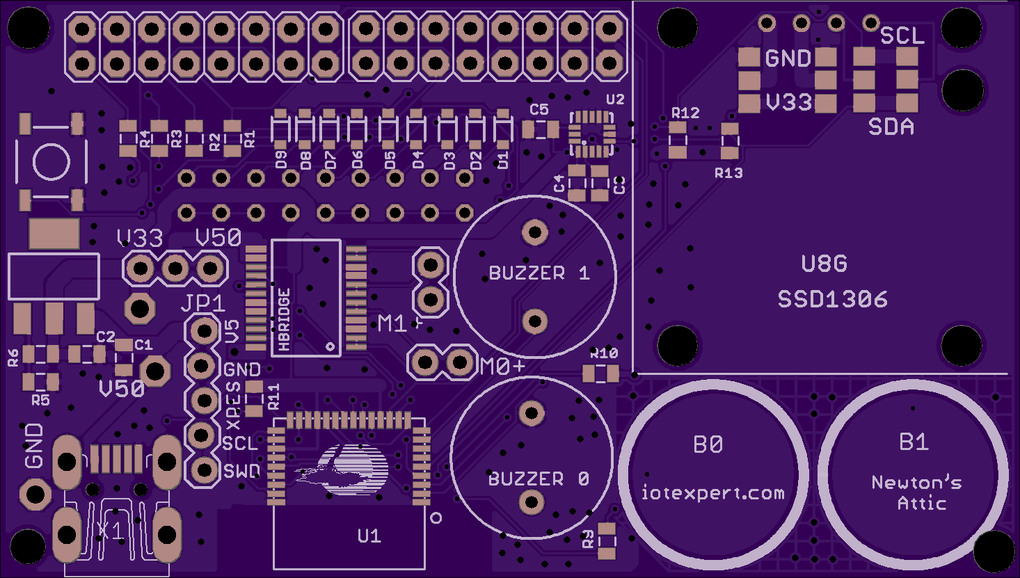
Here is the OSH park rendering of the new PCB layout.
Fix the flipped footprint
I would have bet money that I fixed the Eagle library to have the correct foot print when I did PCB 1.1. However, after I renumbered the pins in the package editor, I did not unhook and then rehook them in the library editor. The result was a flipped footprint, again. What is particularly frustrating is that I didn’t recheck it on the PCB. I now have added that to my PCB checklist.
Put a 1″ LCD screen on the board
On one of our WICED WiFi development kits, the IoT team put a really cool 1″ OLED LCD screen.
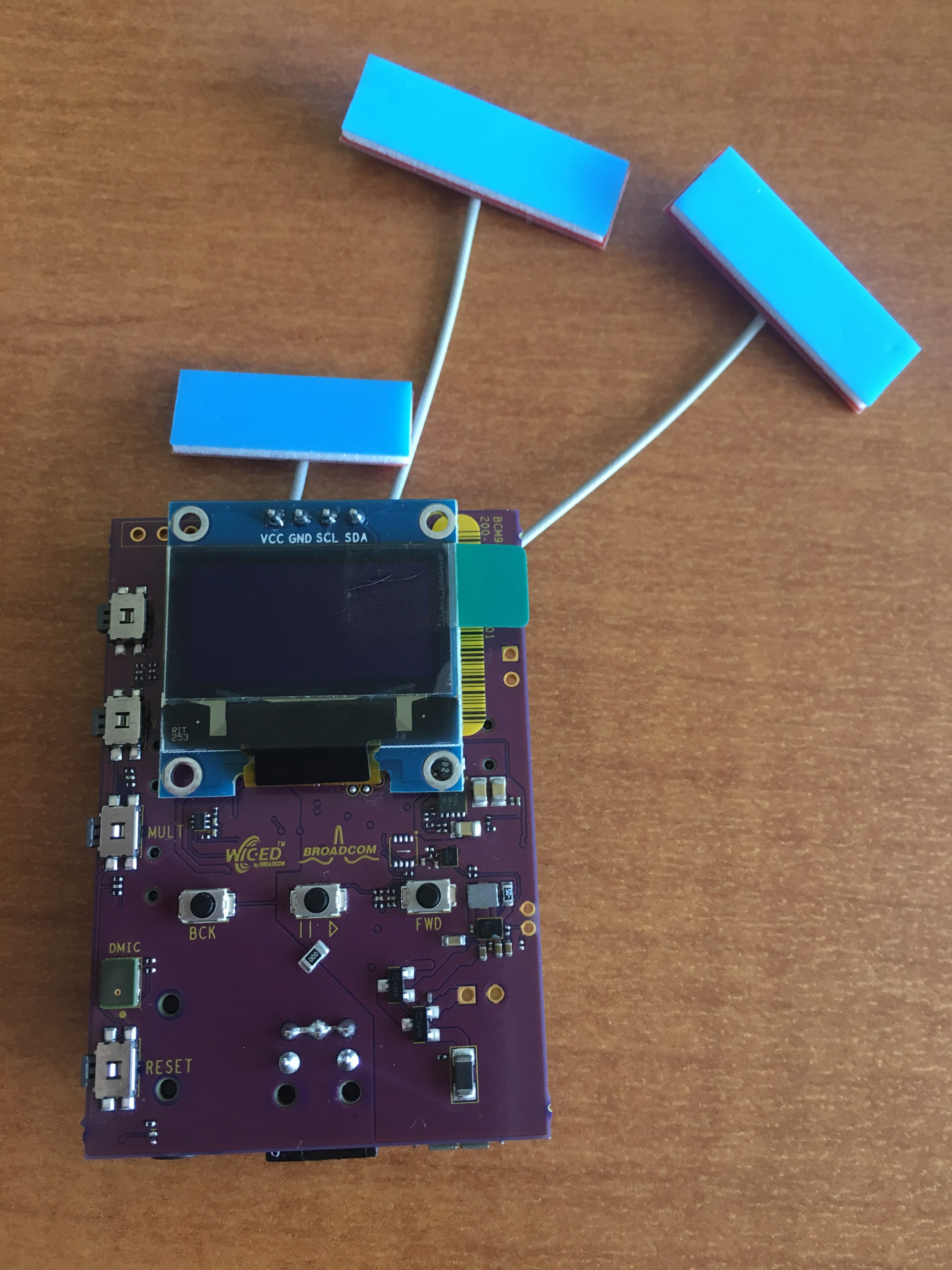
After I looked around a little bit, I found that the little screen was very available for $3-ish on eBay. My original plan was to use a bigger screen with an external connector. But these aren’t as cool and they cost $8. See what I am saying?
In the upper right hand part of the PCB, I extended it a little bit and put on the footprint. The only hitch is that it appears sometimes the pins are “VCC/GND” and sometimes the pins are “GND/VCC”. In order to handle this, I setup four 0-Ohm resistors to allow me to switch the pins.
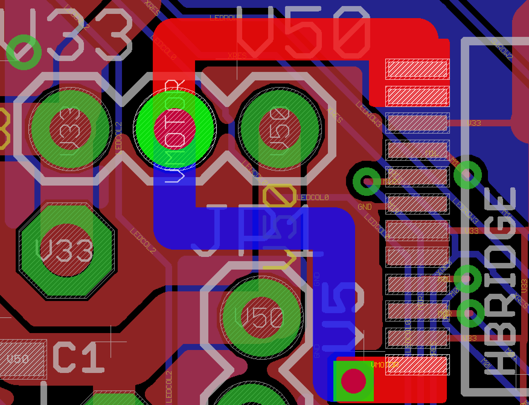
Move the whole system to 3.3v and simplify the power routing
There was no reason to run the system on 5V other than giving a little bit of extra power to the motors. So, to simplify things I moved the PSoC to 3.3V (which it will happily do). That allowed me to remove the level translator that I was using for the accelerometer. By doing this, I could move all of the 5V power to the far left of the PCB, and not route it all over the place. Here is a screen shot of the PCB layout. You can see that the power comes in from the USB connector, then goes straight to three places
- The 3.3v Regulator
- The Mini-Prog-3 Connector
- The Motor Power Selector
Provide a programmable 5v source for the motors
I setup the motor power to be either 3.3v or 5.0v based on the selection of a jumper. The jumper is a 3-position header on 100 mil spacing.
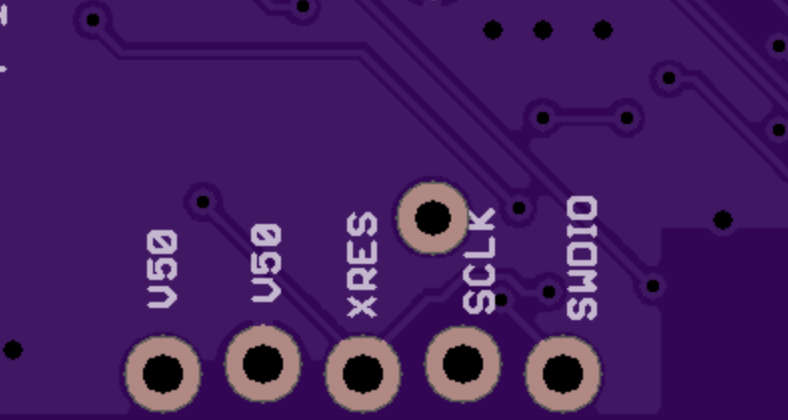
Fix the USB footprint to a USB plug that can be purchased
In the first version of the Pinball PCB layout I used a USB footprint that I found on the internet. But, it turns out that footprint was not available. In fact, I had to search and search for those parts. I finally found a scrap shop in Poland that had a few of them available. That was a bad idea. Here is the new footprint:
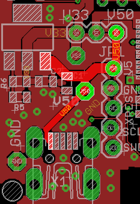
Make the silkscreen more readable (and fix the errors)
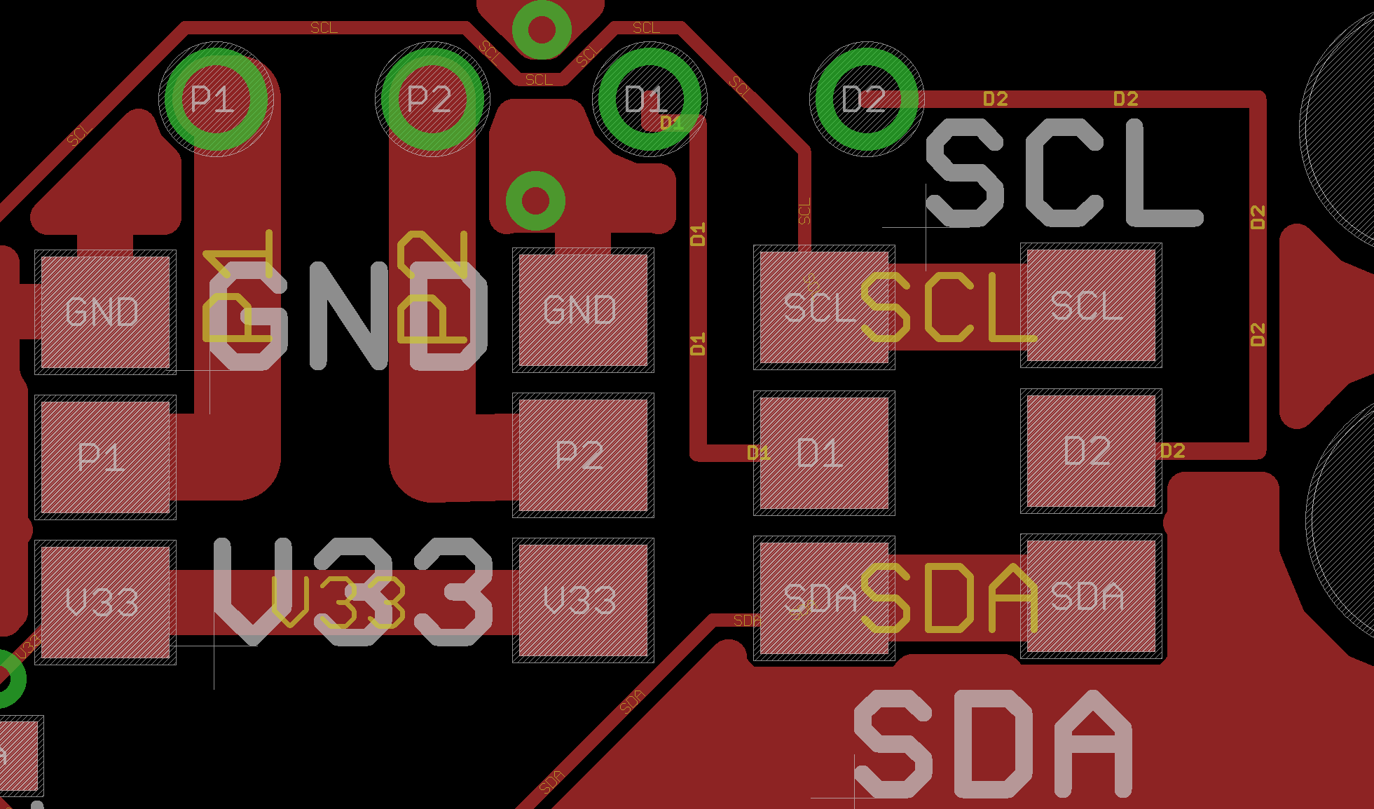
My eyes really don’t like any silkscreen that is less than 30mils tall. There are some people who can see a smaller font, but I am just not one of them. I really prefer 40mil tall letters to occur in my PCB layout. I have updated the checklist with a chart of what is legible and illegible. In addition I had a few errors like the one below (there aren’t two V50 pins next to each other, one is supposed to be ground.)
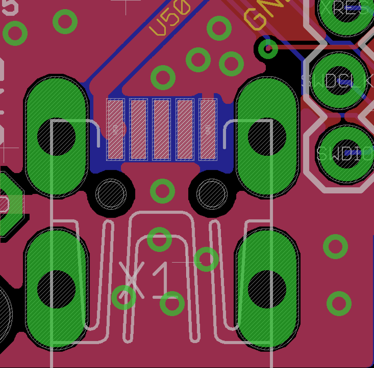
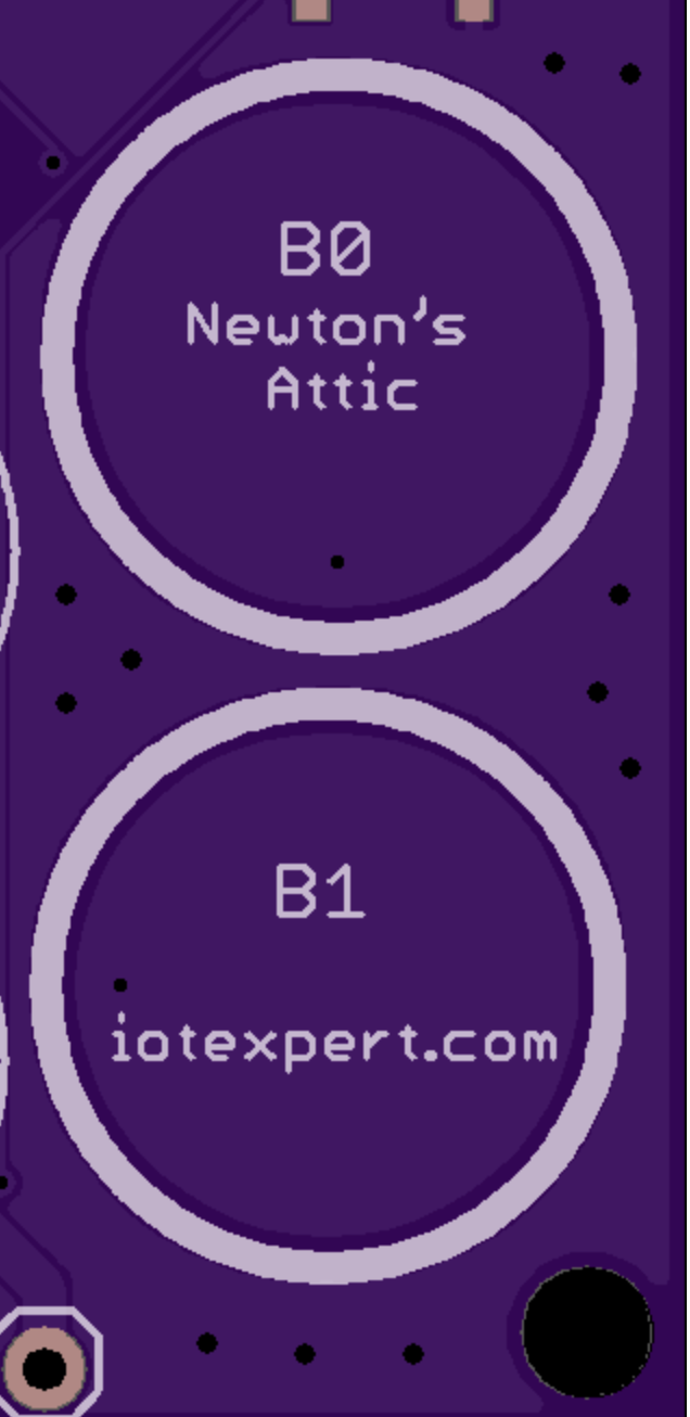
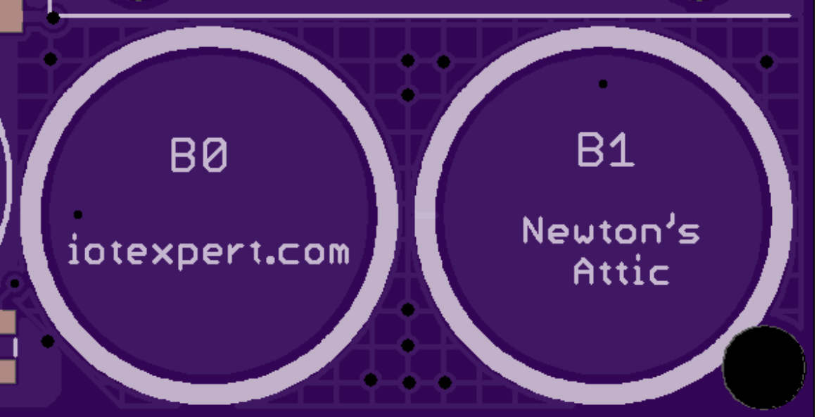
Fix the ground plane grid on the CapSense Buttons
To get the best CapSense performance you should not use a solid ground plane in your PCB layout (like the one below). You should use a cross hatched ground (like the picture at the bottom). You can read about this in the Cypress application note or in my design guidelines.
You can find all of the source code and files at the IOTEXPERT site on github.
Index
Description
Pinball: Newton's Attic Pinball
An introduction to the project and the goals
Pinball: Lotsa Blinking LEDs
Everyone needs a bunch of LEDs on their Pinball Machine
Pinball: Matrix LEDs (Part 1)
Saving PSoC pins by using a matrix scheme
Pinball: Matrix LEDs (Part 2)
Solving some problems with the matrix
Pinball: Matrix LEDs Component
How to turn the Matrix LED into a component
Pinball: A Switch Matrix
Implementing a bunch of switches
Pinball: Switch Matrix Component (Part 1)
The switch matrix component implementation
Pinball: Switch Matrix Component (Part 2)
The firmware for matrix component
Pinball: Switch Matrix Component (Part 3)
Test firmware for the matrix component
Pinball: The Music Player (Part 1)
The schematic and symbol for a Music Player component
Pinball: The Music Player (Part 2)
The Public API for the Music Player component
Pinball: The Music Player (Part 3)
The firmware to make the sweet sweet music
Pinball: The Music Player (Part 4)
The test program for the music player
Pinball: The Motors + HBridge
Using an Bridge to control DC Motors
Pinball: The Eagle Schematic
All of the circuits into an Eagle schematic
Pinball: The Printed Circuit Board 1.0
The first Eagle PCB layout of the printed circuit board
Pinball: The PCB Version 1.0 Fail
Problems with the first version of the Eagle PCB layout
Pinball: PCB Layout 1.2 Updates using Eagle
Fixing the errors on the first two versions of the Eagle PCB
Pinball: Assemble and Reflow the 1.2 PCB
Assembling the Eagle PCB
Pinball: Testing the Eagle PCB
Firmware to test the newly built Pinball printed circuit board
Pinball: Debugging the Motor Driver
Fixing the motor driver PSoC project
Pinball: Hot-Air Reworking the Accelerometer Solder
Using a Hot-Air Rework tool to reflow a QFN
Pinball: Debugging the LM317 Power Supply- A Tale of Getting Lucky
Debugging the LM317/LM117 power supply
No comment yet, add your voice below!