AnyCloud – Wireless Connection Manager (Part 2)

Summary

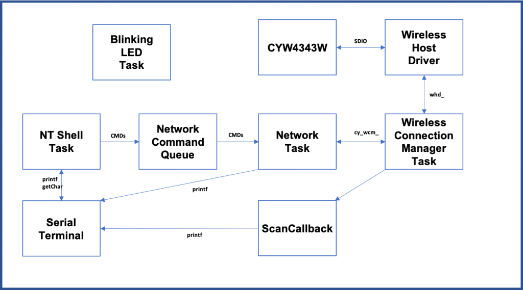
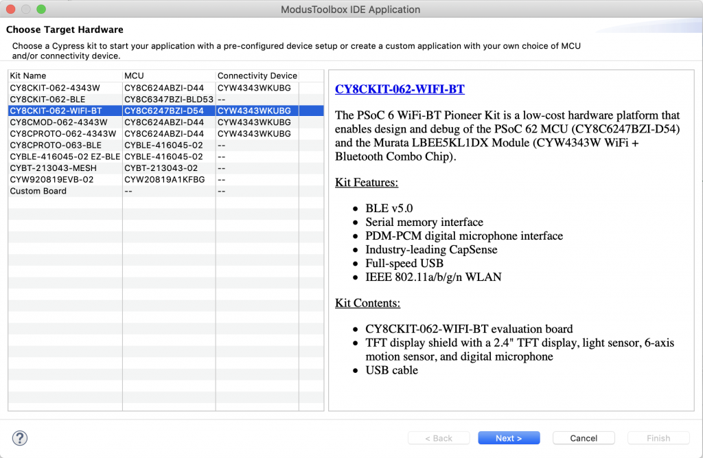
Part 2 of the discussion of using the Infineon (Cypress) PSoC 6 with a CYW4343W and the AnyCloud Connection Manager with Modus Toolbox.  The AnyCloud Connection Manager is an RTOS thread that lets you manage a connection to a WiFi network.  It knows how to scan for networks, attach, detach etc. and was recently released for use with PSoC6 and 43xxx WiFi combos.

The Story

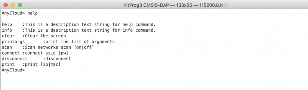
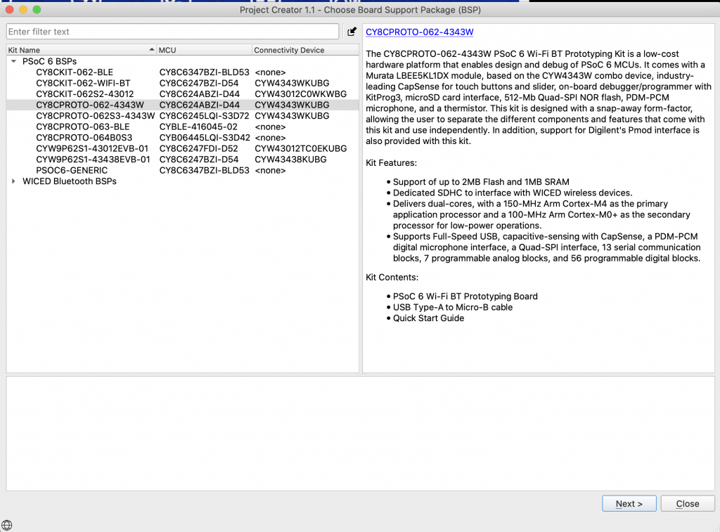
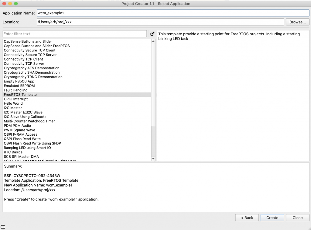
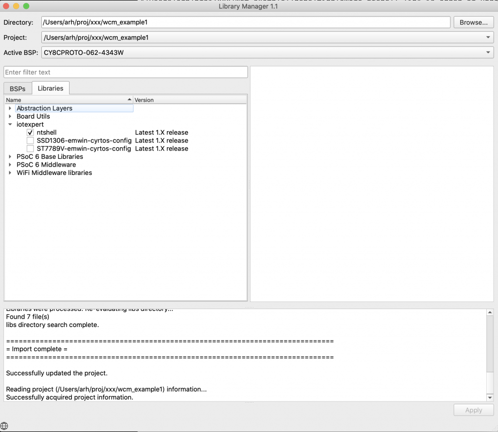
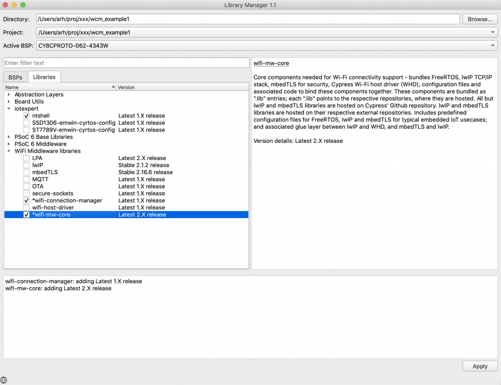
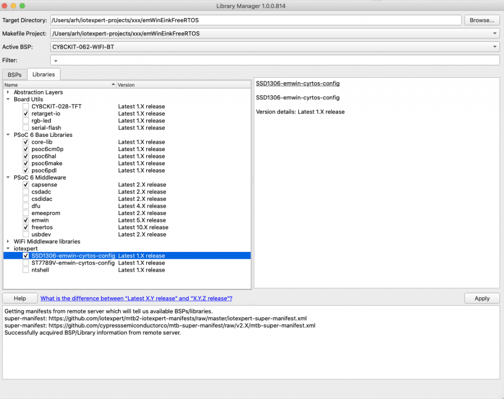
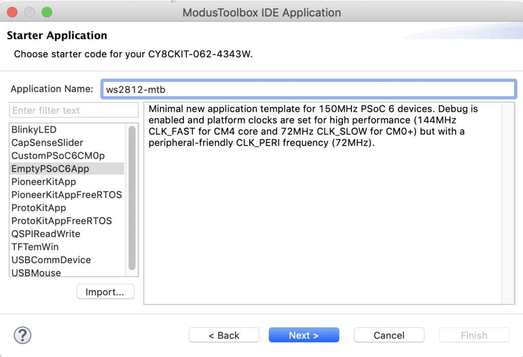
In the last article I walked you through creating a project using the wireless connection manager (WCM) which is one of the libraries that is part of the Infineon/Cypress AnyCloud SDK.  I introduced the wifi-mw-core, wifi-connection-manager and ntshell libraries.  In this article I will update the program to include commands to

  • connect (to an Access Point)
  • disconnect (from an Access Point)
  • print (mac address and ip address)

Add the Connect

I want to add a command that will let me issue a command line like

  • connect SSID (if it doesn’t have a passphrase)
  • connect SSID passphrase

In order to connect to an Access Point you need to call the WCM API, cy_wcm_connect_ap.  Here is the function prototype:

cy_rslt_t cy_wcm_connect_ap(const cy_wcm_connect_params_t *connect_params, cy_wcm_ip_address_t *ip_addr)

This function requires that you give it two arguments

  1. A pointer for a place to store the IP address (that comes from the DHCP server)
  2. A pointer to a structure of connection parameters.  That structure is as follows:
typedef struct
{
    cy_wcm_ap_credentials_t  ap_credentials;       /**< Access point credentials */
    cy_wcm_mac_t             BSSID;                /**< Specifies the MAC address of Access Point (optional) */
    cy_wcm_ip_setting_t      *static_ip_settings;  /**< Specifies the static IP settings of the device (optional) */
    cy_wcm_wifi_band_t       band;                 /**< Specifies the Radio band to be connected (optional) */
} cy_wcm_connect_params_t;

Typically you would setup the “ap_credentials” part of the structure (unless you happen to know the MAC address of the AP you want to connect to).  Those credentials include the SSID and password as well as the security (WPA2 PSK etc…)

typedef struct
{
    cy_wcm_ssid_t        SSID;                /**< SSID of the Wi-Fi network to join, SSID should be a null terminated string. */
    cy_wcm_passphrase_t  password;            /**< Password needed to join the AP, password should be a null terminated string. */
    cy_wcm_security_t    security;            /**< Wi-Fi Security. @see cy_wcm_security_t. */
} cy_wcm_ap_credentials_t;

Security is an enumeration of possible security types.

typedef enum
{
WHD_SECURITY_OPEN             = 0,                                                                 /**< Open security                                         */
WHD_SECURITY_WEP_PSK          = WEP_ENABLED,                                                       /**< WEP PSK Security with open authentication             */
WHD_SECURITY_WEP_SHARED       = (WEP_ENABLED | SHARED_ENABLED),                                    /**< WEP PSK Security with shared authentication           */
WHD_SECURITY_WPA_TKIP_PSK     = (WPA_SECURITY | TKIP_ENABLED),                                     /**< WPA PSK Security with TKIP                            */
WHD_SECURITY_WPA_AES_PSK      = (WPA_SECURITY | AES_ENABLED),                                      /**< WPA PSK Security with AES                             */
WHD_SECURITY_WPA_MIXED_PSK    = (WPA_SECURITY | AES_ENABLED | TKIP_ENABLED),                       /**< WPA PSK Security with AES & TKIP                      */
WHD_SECURITY_WPA2_AES_PSK     = (WPA2_SECURITY | AES_ENABLED),                                     /**< WPA2 PSK Security with AES                            */
WHD_SECURITY_WPA2_TKIP_PSK    = (WPA2_SECURITY | TKIP_ENABLED),                                    /**< WPA2 PSK Security with TKIP                           */
WHD_SECURITY_WPA2_MIXED_PSK   = (WPA2_SECURITY | AES_ENABLED | TKIP_ENABLED),                      /**< WPA2 PSK Security with AES & TKIP                     */
WHD_SECURITY_WPA2_FBT_PSK     = (WPA2_SECURITY | AES_ENABLED | FBT_ENABLED),                       /**< WPA2 FBT PSK Security with AES & TKIP */
WHD_SECURITY_WPA3_SAE         = (WPA3_SECURITY | AES_ENABLED),                                     /**< WPA3 Security with AES */
WHD_SECURITY_WPA3_WPA2_PSK    = (WPA3_SECURITY | WPA2_SECURITY | AES_ENABLED),                     /**< WPA3 WPA2 PSK Security with AES */
WHD_SECURITY_WPA_TKIP_ENT     = (ENTERPRISE_ENABLED | WPA_SECURITY | TKIP_ENABLED),                /**< WPA Enterprise Security with TKIP                     */
WHD_SECURITY_WPA_AES_ENT      = (ENTERPRISE_ENABLED | WPA_SECURITY | AES_ENABLED),                 /**< WPA Enterprise Security with AES                      */
WHD_SECURITY_WPA_MIXED_ENT    = (ENTERPRISE_ENABLED | WPA_SECURITY | AES_ENABLED | TKIP_ENABLED),  /**< WPA Enterprise Security with AES & TKIP               */
WHD_SECURITY_WPA2_TKIP_ENT    = (ENTERPRISE_ENABLED | WPA2_SECURITY | TKIP_ENABLED),               /**< WPA2 Enterprise Security with TKIP                    */
WHD_SECURITY_WPA2_AES_ENT     = (ENTERPRISE_ENABLED | WPA2_SECURITY | AES_ENABLED),                /**< WPA2 Enterprise Security with AES                     */
WHD_SECURITY_WPA2_MIXED_ENT   = (ENTERPRISE_ENABLED | WPA2_SECURITY | AES_ENABLED | TKIP_ENABLED), /**< WPA2 Enterprise Security with AES & TKIP              */
WHD_SECURITY_WPA2_FBT_ENT     = (ENTERPRISE_ENABLED | WPA2_SECURITY | AES_ENABLED | FBT_ENABLED),  /**< WPA2 Enterprise Security with AES & FBT               */
WHD_SECURITY_IBSS_OPEN        = (IBSS_ENABLED),                                                    /**< Open security on IBSS ad-hoc network                  */
WHD_SECURITY_WPS_SECURE       = AES_ENABLED,                                                       /**< WPS with AES security                                 */
WHD_SECURITY_UNKNOWN          = -1,                                                                /**< May be returned by scan function if security is unknown. Do not pass this to the join function! */
WHD_SECURITY_FORCE_32_BIT     = 0x7fffffff                                                         /**< Exists only to force whd_security_t type to 32 bits */
} whd_security_t;

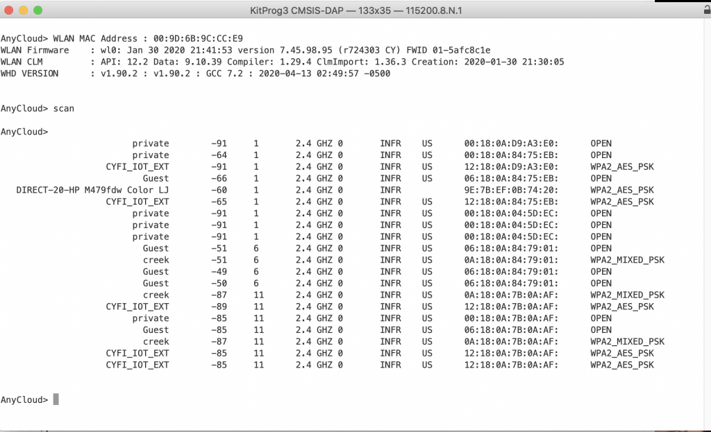
Having to know the security of the AP is a total pain in the neck.  Where do you find the security from?  It turns out that when an AP beacons, the security of that SSID is one of the things that is broadcast.  What this means is that my program will need to

  1. When the connect command is called it should scan for the SSID that is part of the connect command & wait
  2. When the scan finds that SSID it will put the security type into the correct datastructure
  3. Then call the connect.

The way that I will do this is to

  1. Build a filter (that looks only for the user specified SSID)
  2. Provides a pointer for a place to store the security type.

I use the cy_wcm_scan function to do this.  Here is the function prototype:

cy_rslt_t cy_wcm_start_scan(cy_wcm_scan_result_callback_t callback, void *user_data, cy_wcm_scan_filter_t *scan_filter)

The scan filter is just a structure that specified

  1. A mode (which type of filter you want)
  2. The specific thing that you are looking for.
typedef struct
{
cy_wcm_scan_filter_type_t      mode;        /**< Scan filter mode */
union
{
cy_wcm_ssid_t              SSID;        /**< Service Set Identification */
cy_wcm_mac_t               BSSID;       /**< MAC address of Access Point */
cy_wcm_wifi_band_t         band;        /**< Radio band */
cy_wcm_scan_rssi_range_t   rssi_range;  /**< RSSI range */
} param;                                    /**< Scan filter mode specific paramter */
} cy_wcm_scan_filter_t;

The mode is simply an enumeration of the types of filters:

typedef enum
{
CY_WCM_SCAN_FILTER_TYPE_SSID = 0,   /**< Denotes SSID based scan filtering */
CY_WCM_SCAN_FILTER_TYPE_MAC,        /**< Denotes MAC  based scan filtering */
CY_WCM_SCAN_FILTER_TYPE_BAND,       /**< Denotes BAND based scan filtering */
CY_WCM_SCAN_FILTER_TYPE_RSSI,       /**< Denotes RSSI based scan filtering */
}cy_wcm_scan_filter_type_t;

What I want to do is start the scan and then wait for a semaphore.  To do this I will create a semaphore variable at the top of the netTask.c

SemaphoreHandle_t scanApSempahore = NULL;

Inside of the switch I will

  1. Create a connection parameters structure (line 226-227)
  2. setup the scan filter (line 231-232)
  3. create the semaphore (line 235)
  4. run the scan (line 236)
  5. wait for the semaphore to be set or timeout (line 239) notice that I hardcoded it to 10 seconds
				cy_wcm_connect_params_t connect_params;
memset(&connect_params, 0, sizeof(cy_wcm_connect_params_t));
// setup scan filter - In order to connect to an SSID you need to know the security type
// To find the security I scan for JUST that SSID which will tell me the security type
scanFilter.mode = CY_WCM_SCAN_FILTER_TYPE_SSID;
strcpy((char *)scanFilter.param.SSID,(char *)msg.val0);
// The scan callback will either 1) unlock the semaphore or 2) timeout (meaning it didnt find it)
scanApSempahore = xSemaphoreCreateBinary();
cy_wcm_start_scan(findApCallback,&connect_params.ap_credentials.security,&scanFilter);
// The semaphore will return pdFALSE if it TIMES out or pdTrue IF it got unlocked by the scan
if(xSemaphoreTake( scanApSempahore, pdMS_TO_TICKS(10000)) == pdTRUE)

In the scan callback I will check to see if I have real data (in other words the scan is not complete).  In the setup above I made the user data be a pointer to the place to store the security.  On line 54 I will store the security type that came back from the scan in the place pointed to by the user data pointer.  Then I will stop the scan and give the semaphore.

// This callback is used to find a specific SSID and then store the security type into the user data
// When I want to connect it will scan with a "filter" and the user data will be a pointer to the
// place to store the security
void findApCallback( cy_wcm_scan_result_t *result_ptr, void *user_data, cy_wcm_scan_status_t status )
{
if(status == CY_WCM_SCAN_INCOMPLETE)
{
whd_security_t *mySecurity = (whd_security_t *)user_data;
*mySecurity = result_ptr->security;
cy_wcm_stop_scan();
xSemaphoreGive(scanApSempahore);
}
}

Now back in the switch statement you can actually connect because you know the security type (line 244)  The else clause on line 253 handles the case where the timeout of the semaphore occurred, meaning that the scan didn’t find the AP.

				// The semaphore will return pdFALSE if it TIMES out or pdTrue IF it got unlocked by the scan
if(xSemaphoreTake( scanApSempahore, pdMS_TO_TICKS(10000)) == pdTRUE)
{
strcpy((char *)connect_params.ap_credentials.SSID,(char *)msg.val0);
strcpy((char *)connect_params.ap_credentials.password,(char *)msg.val1);
result = cy_wcm_connect_ap(&connect_params,&ip_addr);
if(result == CY_RSLT_SUCCESS)
printf("Connect Succeeded SSID=%s\n",(char *)msg.val0);
else
{
printf("Connect to %s failed\n",(char *)msg.val0);
}	
}
else
{
printf("Scan semaphore failed - couldnt find AP\n");
}
free((void *)msg.val0); // Free the SSID and PW that was passed by the caller
free((void *)msg.val1);
}
break;

With all of the connection work done, you can add the scan command to “usrcmd.c”.  It just looks at the number of arguments (either 2 or 3), then sets up the message to send to the network task, the queues the message.

static int usrcmd_connect(int argc, char **argv)
{
networkQueueMsg_t msg;
if(argc == 2)
{
msg.val0 = (uint32_t)malloc(strlen(argv[1])+1);
msg.val1 = (uint32_t)malloc(sizeof(""));
strcpy((char *)msg.val0,argv[1]);
strcpy((char *)msg.val1,"");
msg.cmd = net_connect;
xQueueSend(networkQueue,(const void *)&msg,portMAX_DELAY);
}
if(argc == 3)
{
msg.val0 = (uint32_t)malloc(strlen(argv[1])+1);
msg.val1 = (uint32_t)malloc(strlen(argv[2])+1);
strcpy((char *)msg.val0,argv[1]);
strcpy((char *)msg.val1,argv[2]);
msg.cmd = net_connect;
xQueueSend(networkQueue,(const void *)&msg,portMAX_DELAY);
}
return 0;
}

Add the Disconnect Command

The disconnect command is trivial.  Just call the disconnect api.

			case net_disconnect:
cy_wcm_disconnect_ap();
break;

Which you also need to add to the usercmd.c

static int usrcmd_disconnect(int argc, char **argv)
{
networkQueueMsg_t msg;
msg.cmd = net_disconnect;
xQueueSend(networkQueue,(const void *)&msg,portMAX_DELAY);
return 0;
}

Add the Print Command

The print command will have two optional parameters, IP (to print the current IP address) and MAC (to print our MAC address).  The first command is print ip.

			case net_printip:
result = cy_wcm_get_ip_addr(CY_WCM_INTERFACE_TYPE_STA,&ip_addr,1);
if(result == CY_RSLT_SUCCESS)
{
printf("IP Address=");
printIp(&ip_addr);
printf("\n");
}
else if(result == CY_RSLT_WCM_NETWORK_DOWN)
printf("Network disconnected\n");
else 
printf("IP Address call return unknown %d\n",(int)result);
break;

The MAC address command is also simple:

			case net_printmac:
result = cy_wcm_get_mac_addr(CY_WCM_INTERFACE_TYPE_STA,&mac_addr,1);
if(result == CY_RSLT_SUCCESS)
{
printf("MAC Address =");
printMac(mac_addr);
printf("\n");
}
else
printf("MAC Address = Unknown\n");
break;
}

And you need to add the print command to usrcmd.c

static int usrcmd_print(int argc, char **argv)
{
networkQueueMsg_t msg;
if(argc == 2 && strcmp(argv[1],"ip")==0)
{
msg.cmd = net_printip;
xQueueSend(networkQueue,(const void *)&msg,portMAX_DELAY);
}
if(argc == 2 && strcmp(argv[1],"mac")==0)
{
msg.cmd = net_printmac;
xQueueSend(networkQueue,(const void *)&msg,portMAX_DELAY);
}
return 0;
}

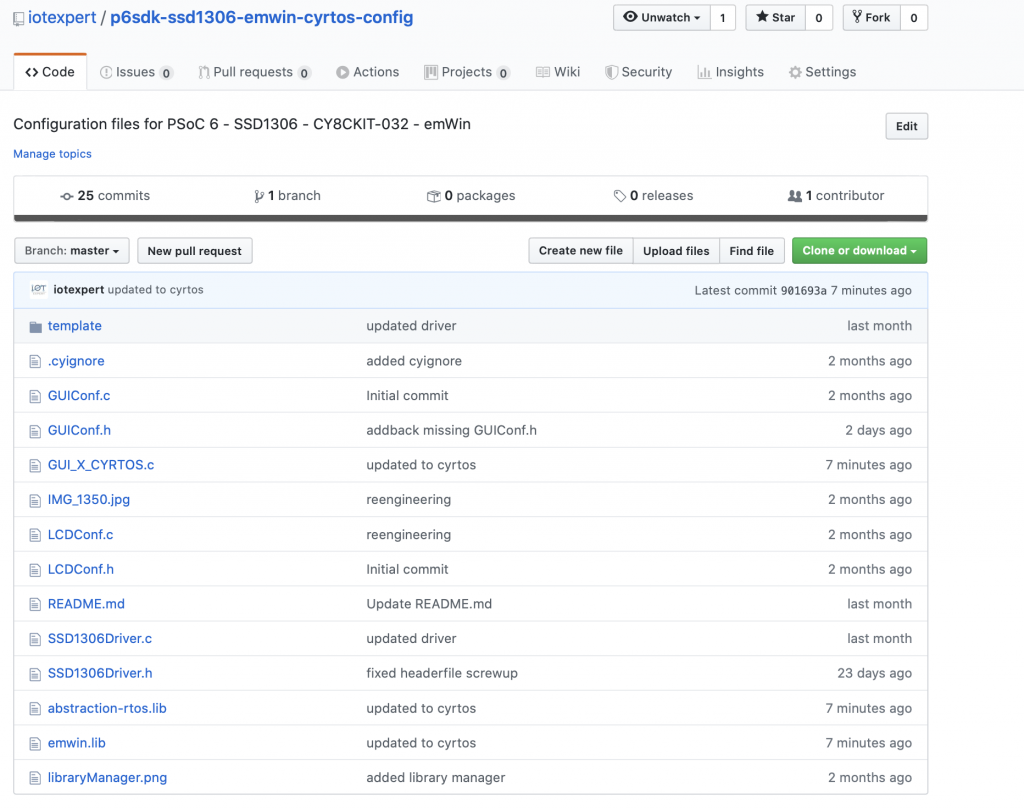
All of this code is available on github at

  • git@github.com:iotexpert/wcm_example
  • https://github.com/iotexpert/wcm_example

AnyCloud – Wireless Connection Manager (Part 1)

Summary

A discussion of using the Infineon (Cypress) PSoC 6 with a CYW4343W and the AnyCloud Connection Manager with Modus Toolbox.  The AnyCloud Connection Manager is an RTOS thread that lets you manage a connection to a WiFi network.  It knows how to scan for networks, attach, detach etc. and was recently released for use with PSoC6 and 43xxx WiFi combos.

The Story

In the WICED WiFI SDK there is an example program called “test.console” which allows you to use a UART command line to do networking “stuff”.  With the release of the new AnyCloud SDK I decided that I should rebuild some of that program using the PSoC and WiFi.  Basically a set of commands like “scan” to interact with the Radio World!  In the picture you below you can see that I use the command “scan” to list out the networks at my house.

You can also use the command “help” to list out the commands.

Architecture

My implementation will have three tasks

  1. A Blinking LED Task (which doesn’t interact with any other tasks)
  2. The NT Shell – which will send commands to the network queue.
  3. The Network Task which will receive commands from the NT Shell task and trigger the Wireless Connection Manager to do something
  4. The Wireless Connection Manager which will interact with the WiFI Radio via the Wireless Host driver.

Make the Basic Project

To build this project start by creating a new project.  The development board that I had plugged into my computer when I began this project is a CY8CPROTO-062-4343W so this is the one I will select.

In the new project creator pick the “CY8CPROTO-062-4343W”

I created a FreeRTOS template project that does all of the right stuff.  I wrote an article about how to use the IoT Expert Manifestt here, and until you add the IoT Manifest to your setup you will not get the FreeRTOS Template project.

After the new project work is done you should see

Add the nt-shell, which comes from my IoT Expert library (read about how to add the IoT Expert library here).

I have been on a kick of using Visual Studio code.  So, run “make vscode” to setup the project for Visual Studio Code.

In the finder, copy the template files from nt-shell into your project.

You can also do it with the command line.

Edit main.c to include the configuration.

#include "ntshell.h"
#include "psoc6_ntshell_port.h"

Update the main.c to have the ntShellThread

// Global variable with a handle to the shell
ntshell_t ntshell;
void ntShellTask()
{
printf("Started ntshell\n");
setvbuf(stdin, NULL, _IONBF, 0);
ntshell_init(
&ntshell,
ntshell_read,
ntshell_write,
ntshell_callback,
(void *)&ntshell);
ntshell_set_prompt(&ntshell, "AnyCloud> ");
vtsend_erase_display(&ntshell.vtsend);
ntshell_execute(&ntshell);
}

And start the ntshell task.

    xTaskCreate(ntShellTask, "nt shell task", configMINIMAL_STACK_SIZE*2,0 /* args */ ,4 /* priority */, 0);

When you want to add a command to the shell you need to do three things

  1. Add a function prototype for the command
  2. Add the command to the command list
  3. Write the function
static int usrcmd_help(int argc, char **argv);
static int usrcmd_info(int argc, char **argv);
static int usrcmd_clear(int argc, char **argv);
static int usrcmd_printargs(int argc, char **argv);
static const cmd_table_t cmdlist[] = {
{ "help", "This is a description text string for help command.", usrcmd_help },
{ "info", "This is a description text string for info command.", usrcmd_info },
{ "clear", "Clear the screen", usrcmd_clear },
{ "printargs","print the list of arguments", usrcmd_printargs},
};

Here is an example of of the printargs command.  The shell will call your function with a ARGC=number of arguments and ARGV[] an array of the pointers to the actual arguments.

static int usrcmd_printargs(int argc, char **argv)
{
printf("ARGC = %d\n",argc);
for(int i =0;i<argc;i++)
{
printf("argv[%d] = %s\n",i,argv[i]);
}
return 0;
}

Build and test your program.

Turn on the Connection Manager and Core Middleware Library

Now, add the wifi-mw-core library & Connection Manager using the library manager.  You can start it with “make modlibs”.  These two libraries are in the “WiFi Middleware” category.

Copy the FreeRTOSConfig.h from the libs/wifi-mw-core/configs directory into your project (so you can modify it)

Update the Makefile to include the WiFi components (line 71) and the MBED TLS configuration (line 86)

COMPONENTS=FREERTOS PSOC6HAL LWIP MBEDTLS 4343W
# Like COMPONENTS, but disable optional code that was enabled by default.
DISABLE_COMPONENTS=
# By default the build system automatically looks in the Makefile's directory
# tree for source code and builds it. The SOURCES variable can be used to
# manually add source code to the build process from a location not searched
# by default, or otherwise not found by the build system.
SOURCES=
# Like SOURCES, but for include directories. Value should be paths to
# directories (without a leading -I).
INCLUDES=
# Add additional defines to the build process (without a leading -D).
DEFINES=MBEDTLS_USER_CONFIG_FILE='"configs/mbedtls_user_config.h"' CYBSP_WIFI_CAPABLE

Create networkTask.h/.c & Start the Task in main.c

Now let’s create the networkTask.  This task will control all of the networking functions in the system.  The first file, networkTask.h, is the public interface.  It declares a Queue where you can push messages (line 5) an enumeration of the messages (lines 7-14), a definition of the message data (lines 17-22) and finally the network task declaration (line 24).

#pragma once
#include "FreeRTOS.h"
#include "queue.h"
extern QueueHandle_t networkQueue;
typedef enum {
net_scan,
net_connect,
net_disconnect,
net_printip,
net_printmac,
} networkCmd_t;
typedef struct {
networkCmd_t cmd;
uint32_t val0;
uint32_t val1;
} networkQueueMsg_t;
void networkTask(void *arg);

Ill go ahead and modify main.c to start the yet to be written network task.  You need to include the header file for the task and define a handle for the task.

#include "networkTask.h"
TaskHandle_t networkTaskHandle;

Finally in main function, start the task.

    xTaskCreate(networkTask, "networkTask", configMINIMAL_STACK_SIZE*8,0 /* args */ ,4/* priority */, &networkTaskHandle);

Create the file networkTask.c.  Make a bunch of includes.

#include <stdio.h>
#include <stdlib.h>
#include "FreeRTOS.h"
#include "task.h"
#include "cy_wcm.h"
#include "cy_wcm_error.h"
#include "whd_types.h"
#include "queue.h"
#include "semphr.h"
#include "networkTask.h"

Now let’s define the actual task function.  This function will

  1. Call the wcm_init function to make a WiFi Station (lines 201-203)
  2. Tell the task that you would like to be called back when things happen (line 205)
  3. Initialize the Queue to receive command messages from other tasks.
  4. Make an infinite loop to receive the commands and process the messages.  Notice that I dont do anything with the message for now.  Ill add the code later.
// The networkTask will:
// - startup the wireless connection manager
// - sit waiting on the rtos queue... getting messages from other tasks
// - and do ( net_scan, net_connect, net_disconnect, net_printip, net_printmac,)
void networkTask(void *arg)
{
cy_rslt_t result;
cy_wcm_config_t config;
cy_wcm_scan_filter_t scanFilter;
memset(&config, 0, sizeof(cy_wcm_config_t));
config.interface = CY_WCM_INTERFACE_TYPE_STA;
cy_wcm_init	(&config);
cy_wcm_register_event_callback(	wcmCallback	);
networkQueue = xQueueCreate( 5, sizeof(networkQueueMsg_t));
while(1)
{
networkQueueMsg_t msg;
xQueueReceive(networkQueue,(void *)&msg,portMAX_DELAY);  // Wait for commands from other tasks
switch(msg.cmd)
{
case net_scan: // 0=stop scan !0=start scan
break;
case net_connect:
break;
case net_disconnect:
break;
case net_printip:
break;
case net_printmac:
break;
}
}
}

Create Utilities for Printing out the IP and MAC Address

It the network task I want to be able to print out IP address (both IPV4 and IPV6).  I also want to be able to print out 6-byte MAC address.  In the Cypress drivers, an IP address is a structure that holds either a IPV4 or and IPV6 address.  It then contains the 4 or 6 bytes of the address.  Here is the type definition.

/**
* IP Address Structure
*/
typedef struct
{
cy_wcm_ip_version_t version;  /**< IP version */
union
{
uint32_t v4;     /**< IPv4 address bytes */
uint32_t v6[4];  /**< IPv6 address bytes */
} ip;                /**< IP address bytes */
} cy_wcm_ip_address_t;

The IP v ersion is just an enumeration.

/**
* IP Version
*/
typedef enum
{
CY_WCM_IP_VER_V4 = 4,      /**< Denotes IPv4 version */
CY_WCM_IP_VER_V6 = 6       /**< Denotes IPv6 version */
} cy_wcm_ip_version_t;

To print an address, figure out which version you are working on.  Then dump the raw bytes.  Notice in the IPV4 case it is encoded into a uint32_t as 4 continuous bytes.

void printIp(cy_wcm_ip_address_t *ipad)
{
if(ip_addr.version == CY_WCM_IP_VER_V4)
{
printf("%d.%d.%d.%d",(int)ipad->ip.v4>>0&0xFF,(int)ipad->ip.v4>>8&0xFF,(int)ipad->ip.v4>>16&0xFF,(int)ipad->ip.v4>>24&0xFF);
}
else if (ip_addr.version == CY_WCM_IP_VER_V6)
{
for(int i=0;i<4;i++)
{
printf("%0X:",(unsigned int)ip_addr.ip.v6[i]);
}
}
else
{
printf("IP ERROR %d",ipad->version);
}			
}

A MAC address is just an array of uint8_t of length CY_WCM_MAC_ADDR_LEN  (which we pound defined to 6)

typedef uint8_t cy_wcm_mac_t[CY_WCM_MAC_ADDR_LEN];                   /**< Unique 6-byte MAC address */

So, the print is just a loop. (probably should have done something slightly better so I dont end up with the trailing : – oh well)

void printMac(cy_wcm_mac_t mac)
{
for(int i=0;i<CY_WCM_MAC_ADDR_LEN;i++)
{
uint8_t val = mac[i];
printf("%02X:",val);
}
}

Add the Scan Command

For the scan I want to print out the:

  1. SSID
  2. RSSI (in dBM)
  3. Channel
  4. Band
  5. Speed
  6. Type of Ap
  7. Country Code
  8. MAC address of the Access Point (AKA BSSID)
  9. Type of Security

In order to have the WCM run a scan you need to call the function cy_wcm_start_scan.  What this will do is tell the 4343W to scan all the channels on the 2.4GHZ band and listen for access point beacons.  This function has three arguments

  1. A function pointer to call back when you find an AP
  2. A user settable data pointer
  3. A filter (which can limit to an SSID, BSSID or RSSI)
cy_rslt_t cy_wcm_start_scan(cy_wcm_scan_result_callback_t callback, void *user_data, cy_wcm_scan_filter_t *scan_filter)

Here is my version of the scanCallback which I put in the networkTask.c file.

// This function is called back when the user asks for an overall scan.
// It just prints out the information about the networks that it hears about
void scanCallback( cy_wcm_scan_result_t *result_ptr, void *user_data, cy_wcm_scan_status_t status )

The result_ptr is a pointer to a structure that contains the data for the found access point.

/**
* Structure for storing scan results
*/
typedef struct
{
cy_wcm_ssid_t                SSID;             /**< Service Set Identification (i.e. Name of Access Point)                    */
cy_wcm_mac_t                 BSSID;            /**< Basic Service Set Identification (i.e. MAC address of Access Point)       */
int16_t                      signal_strength;  /**< Receive Signal Strength Indication in dBm. <-90=Very poor, >-30=Excellent */
uint32_t                     max_data_rate;    /**< Maximum data rate in kilobits/s                                           */
cy_wcm_bss_type_t            bss_type;         /**< Network type                                                              */
cy_wcm_security_t            security;         /**< Security type                                                             */
uint8_t                      channel;          /**< Radio channel that the AP beacon was received on                          */
cy_wcm_wifi_band_t           band;             /**< Radio band                                                                */
uint8_t                      ccode[2];         /**< Two letter ISO country code from AP                                       */
uint8_t                      flags;            /**< flags                                                                     */
uint8_t                      *ie_ptr;          /**< Pointer to received Beacon/Probe Response IE(Information Element)         */
uint32_t                     ie_len;           /**< Length of IE(Information Element)                                         */
} cy_wcm_scan_result_t;

The other parameter to the callback is the status.  The status will either be CY_WCM_SCAN_COMPLETE or CY_WCM_SCAN_INCOMPLETE.  The first thing that to do is see if this callback is the one that tells me that the scan is complete, if so I just return (and don’t print anything)

	if(status == CY_WCM_SCAN_COMPLETE)
return;

Then I print out the raw SSID, Signal Strength and Channel.

	printf("%32s\t%d\t%d\t",result_ptr->SSID,result_ptr->signal_strength,result_ptr->channel);

Next I figure out what channel we are talking about.  The 4343W is single band 2.4GHZ, however, other Cypress chips have dual band.

	switch(result_ptr->band)
{
case CY_WCM_WIFI_BAND_ANY:
printf("ANY");
break;
case CY_WCM_WIFI_BAND_5GHZ:
printf("5.0 GHZ");
break;
case CY_WCM_WIFI_BAND_2_4GHZ:
printf("2.4 GHZ");
break;
}

Then I printout the maximum data rate, which is 0 for all of my test cases.  I have no idea why.

	printf("%d",(int)result_ptr->max_data_rate);

Then I printout what type of AP we are talking about.

	switch(result_ptr->bss_type)
{
case CY_WCM_BSS_TYPE_INFRASTRUCTURE:
printf("INFR");
break; 	
case CY_WCM_BSS_TYPE_ADHOC: 
printf("ADHOC");
break;	
case CY_WCM__BSS_TYPE_ANY: 	
printf("ANY");
break;
case CY_WCM_BSS_TYPE_MESH:
printf("MESG");
break;
case CY_WCM_BSS_TYPE_UNKNOWN: 
printf("UNKWN");
break;
}

Then the country code.

	printf("%c%c",result_ptr->ccode[0],result_ptr->ccode[1]);

Then the Basic Service Set ID of the AP, which is also known as the MAC address of the AP.

	printMac(result_ptr->BSSID);

Then the security type.

	switch(result_ptr->security)
{
case CY_WCM_SECURITY_OPEN:
printf("OPEN");
break;
case CY_WCM_SECURITY_WEP_PSK:
printf("WEP_PSK");
break;
case CY_WCM_SECURITY_WEP_SHARED:
printf("WEP_SHARED");
break;
case CY_WCM_SECURITY_WPA_TKIP_PSK:
printf("WPA_TKIP_PSK");
break;
case CY_WCM_SECURITY_WPA_AES_PSK:
printf("WPA_AES_PSK");
break;
case CY_WCM_SECURITY_WPA_MIXED_PSK:
printf("WPA_MIXED_PSK");
break;
case CY_WCM_SECURITY_WPA2_AES_PSK:
printf("WPA2_AES_PSK");
break;
case CY_WCM_SECURITY_WPA2_TKIP_PSK:
printf("WPA2_TKIP_PSK");
break;
case CY_WCM_SECURITY_WPA2_MIXED_PSK:
printf("WPA2_MIXED_PSK");
break;
case CY_WCM_SECURITY_WPA2_FBT_PSK:
printf("WPA2_FBT_PSK");
break;
case CY_WCM_SECURITY_WPA3_SAE:
printf("WPA3_SAE");
break;
case CY_WCM_SECURITY_WPA3_WPA2_PSK:
printf("WPA3_WPA2_PSK");
break;
case CY_WCM_SECURITY_IBSS_OPEN:
printf("IBSS_OPEN");
break;
case CY_WCM_SECURITY_WPS_SECURE:
printf("WPS_SECURE");
break;
case CY_WCM_SECURITY_UNKNOWN:
printf("UNKNOWN");
break;
case CY_WCM_SECURITY_FORCE_32_BIT:
printf("FORCE_32_BIT");
break;
}

With a complete scanCallback function I can now update the networkTask to deal with the queued commands of net_scan type.  This simply either stops or starts the scan based on the message parameter.

			case net_scan: // 0=stop scan !0=start scan
if(msg.val0 == 0)
cy_wcm_stop_scan();
else
{
printf("\n");
result = cy_wcm_start_scan(scanCallback,0,0);
if(result != CY_RSLT_SUCCESS)
printf("Scan error\n");
}
break;

The last things to do is to add the scan command to the usrcmd.c

static int usrcmd_scan(int argc, char **argv)
{
static int state=0;
if(argc==1)
{
state = (state ==0)?1:0;
}
else if(argc == 2)
{
if(strcmp(argv[1],"on") == 0)
{
state=1;
} 
else if(strcmp(argv[1],"off") == 0)
{
state = 0;
}
else
{
printf("usage: scan [on|off]\n");
return 0;
}
}
else
{
printf("usage scan: [on|off]\n");
return 0;
}
networkQueueMsg_t msg;
msg.cmd = net_scan;
msg.val0 = state;
xQueueSend(networkQueue,(const void *)&msg,portMAX_DELAY);
return 0;
}

OK.  Let it rip.  You should be able to run network scans.  In the next Article I will add a connect and disconnect commands.

You can find all of this example code at https://github.com/iotexpert/wcm_example

PSoC 6 & FreeRTOS Tickless

Summary

This article walks you through the steps to add DeepSleep Tickless mode to your PSoC 6 FreeRTOS project.  It includes an example project that demonstrates the use of the Cypress HAL and DeepSleep to acheive power savings.

This article is part of the "PSoC 6 Low Power Techniques" Series which covers a range of tools you have to lower the power of your system.  The following articles are (or will be) available:

Articles
PSoC 6 Low Power
PSoC 6 & Using the MCWDT as a Deep Sleep Timer
PSoC 6 Deep Sleep Wakeup Time
PSoC 6 & FreeRTOS Tickless
Managing the PSoC 6 Clock Frequency
Using the PSoC 6 LDO and SIMO Buck Regulators for Low Power
Using the PSoC 6 Always on Backup Domain
PSoC 6 Turning off block of RAM

The following resources are available

The Story

I recently taught the Modus Toolbox-101 class to a group of Cypress Field Applications Engineers.  In that class we have a chapter called “PSoC 6 Low Power” which shows you how to use the Low Power Assistant to improve your system power.  This chapter was built around the ARM MBED OS Software Development Kit inside of Modus Toolbox.  Every time I show people the low power assistant I am blown away by how easy it is to do.  Cypress is currently working on a major upgrade to our FreeRTOS implementation, but I thought that in advance of that I would take some of the steps myself.  Specifically, using FreeRTOS Tickless Mode.

What is Tickless mode?  In order to understand this you should understand that FreeRTOS runs a scheduler – and its not just FreeRTOS but every RTOS.  The scheduler is responsible for pausing, starting, stopping etc. the tasks based on your configuration (i.e. priorities).  The scheduler task needs to run on a regular basis, like every 1ms, or the system will fall apart.  This is done for you automatically by hooking up a system tick interrupt which interrupts whatever user task is happening and running the scheduler.

The next thing that you need to know is that RTOSs have a task called “idle” which runs when all of the real tasks are blocked either by a delay, semaphore, queue etc.  All this idle task does is burn CPU cycles until the next SysTick interrupt.  The idle task is implemented with something like while(1);  This isn’t really very constructive because the CPU is active, the clocks are active, etc. and this whole thing typically burns mA’s of current (at least on a PSoC 6).

So, what should you do?  The answer is that instead of “idling” you should put the CPU to Sleep, preferably DeepSleep.  But where should you do that?  The perfect place is in the idle task.  If you setup the idle task to just put the CPU to Sleep/DeepSleep then you save power.

But if the CPU is asleep how do you wakeup and when?  There are two answers to those questions:

  1. If nothing is pending, there are no timers running, you should go to sleep and wait for an interrupt (from an MCU peripheral … like a pin)
  2. If you know that everything is blocked, but a task is supposed to wakeup at some specified time, then you should go to sleep until that time.

But how do you set a wakeup time?  Simple.  Use the PSoC 6 MCWDT as a DeepSleep Low Power Timer.

In this article I will show you how to setup the FreeRTOS configuration files plus the HAL lptimer to achieve goal.  The sections are:

  • PSoC Configurator
  • FreeRTOSConfig.h
  • LowPower.c
  • A Demo Program

PSoC 6 Configurator

If you look at the PSoC 6 device configurator you will find a section called “RTOS”.  This was put by the Low Power Assistant team to enable stuff for MBEDOS.  However, it can/could/will be used for FreeRTOS as well.   All this configuration does is create a section of #defines which can then be used to setup your low power code.

The first parameter is “System Idle Power Mode” which can be set as “Active, CPU Sleep or System Deep Sleep”.

The second parameter is “Deep Sleep Latency” which is an integer which can set the minimum sleep time.  In other words if you are going to sleep less than this number, don’t bother.

When you configure these parameters, it will create the following #defines in the cycfg_system.h

The first three are used because the c-preprocessor can only evaluate integer expressions.  These defines enable you to do compares with the power mode in your code.  The “CY_CFG_PWR_SYS_IDLE_MODE” it set to whatever you specified in the configurator.  Here is a clip from the cycfg_system.h

#define CY_CFG_PWR_MODE_ACTIVE 0x04UL
#define CY_CFG_PWR_MODE_SLEEP 0x08UL
#define CY_CFG_PWR_MODE_DEEPSLEEP 0x10UL
#define CY_CFG_PWR_SYS_IDLE_MODE CY_CFG_PWR_MODE_DEEPSLEEP
#define CY_CFG_PWR_DEEPSLEEP_LATENCY 8UL

FreeRTOSConfig.h

So now what?  Lets use those defines to get FreeRTOS going.  The first thing you need to do is tell FreeRTOS that you want to use TICKLESS IDLE by setting the #define configUSE_TICKLESS_IDLE.  There are three possible settings:

  • 0 or undefined – no tickless idle
  • 1 – use the built-in port (which we did’t supply)
  • 2 – use a application developer supplied low power configuration (this is what we are going to do)

I add this block of code to my FreeRTOSConfig.h.  It says:

63: If the user has selected Sleep or DeepSleep

64: Give me access to the vApplicationSleep function (which I will write)

65: Tell FreeRTOS to call the vApplicationSleep function in the idle task

66: And tell FreeRTOS that I want to use MY OWN implementation of Tickless

69-71: If the user has specified a minimum time, then tell FreeRTOS to use that minimum.

#if CY_CFG_PWR_SYS_IDLE_MODE == CY_CFG_PWR_MODE_SLEEP || CY_CFG_PWR_SYS_IDLE_MODE == CY_CFG_PWR_MODE_DEEPSLEEP
extern void vApplicationSleep( uint32_t xExpectedIdleTime );
#define portSUPPRESS_TICKS_AND_SLEEP( xIdleTime ) vApplicationSleep( xIdleTime )
#define configUSE_TICKLESS_IDLE  2
#endif
#if CY_CFG_PWR_DEEPSLEEP_LATENCY>0
#define configEXPECTED_IDLE_TIME_BEFORE_SLEEP CY_CFG_PWR_DEEPSLEEP_LATENCY
#endif

LowPower.c

Now I need to implement the function “vApplicationSleep” which will look at the state of affairs and “do the needful”.  I decided to put all of the low power stuff a file called “lowPower.c”.   It goes like this:

24-25: Create a low power timer (if I haven’t already)

27-28: Disable the SysTick and disable the ARM global interrupts

31: Ask the RTOS if we REALLY want to go to sleep, which could have changed if there was an interrupt or a task became active before the interrupts were disabled

32: Reset the timer to 0 (so that we can get a maximum delay)

34: If we are really going to go to sleep (in other words we shouldn’t abort)

Remember from above there are two Sleep/DeepSleep cases:

  1. There are no tasks waiting
  2. There is a task waiting

36-40: If there is a task waiting then setup the timer to wakeup in that amount of time

42: Remember when you went to sleep, so you can fix the system timer after you wake backup

43-46: Sleep or DeepSleep (depending on what the user said in the configurator)

48: Or bail if the developer didn’t turn on this code

51: When you wake up find out what time it is

54: Fix the tick count in the RTOS based on how long you slept

56: Disable the lptimer interrupt

61-62: Enable the interrupts and turn the SysTick back on.

#include "FreeRTOS.h"
#include "task.h"
#include "cyhal.h"
#include "cybsp.h"
static inline uint32_t msToTicks(uint32_t ms)
{
uint64_t val = (CY_SYSCLK_WCO_FREQ*(uint64_t)ms/1000);
val = (val>UINT32_MAX)?UINT32_MAX:val;
return (uint32_t)val;
}
static inline uint32_t ticksToMs(uint32_t ticks)
{
return (ticks * 1000) / CY_SYSCLK_WCO_FREQ;
}
/* Define the function that is called by portSUPPRESS_TICKS_AND_SLEEP(). */
void vApplicationSleep( TickType_t xExpectedIdleTime )
{
static cyhal_lptimer_t myTimer={0};
unsigned long ulLowPowerTimeBeforeSleep, ulLowPowerTimeAfterSleep;
if(myTimer.base == 0)
cyhal_lptimer_init(&myTimer);
Cy_SysTick_Disable();
uint8_t interruptState = Cy_SysLib_EnterCriticalSection();
/* Ensure it is still ok to enter the sleep mode. */
eSleepModeStatus eSleepStatus = eTaskConfirmSleepModeStatus();
cyhal_lptimer_reload(&myTimer);
if( eSleepStatus != eAbortSleep )
{
if( eSleepStatus != eNoTasksWaitingTimeout )
{
cyhal_lptimer_set_delay	(&myTimer,msToTicks(xExpectedIdleTime));
cyhal_lptimer_enable_event (&myTimer, CYHAL_LPTIMER_COMPARE_MATCH, 7, true);
}
/* Enter the low power state. */
ulLowPowerTimeBeforeSleep = cyhal_lptimer_read(&myTimer);
#if CY_CFG_PWR_SYS_IDLE_MODE == CY_CFG_PWR_MODE_DEEPSLEEP
cyhal_system_deepsleep();
#elif CY_CFG_PWR_SYS_IDLE_MODE == CY_CFG_PWR_MODE_SLEEP
cyhal_system_sleep();
#else
goto exitPoint;
#endif
// How long did it sleep
ulLowPowerTimeAfterSleep = cyhal_lptimer_read(&myTimer);
/* Correct the kernels tick count to account for the time the microcontroller spent in its low power state. */
vTaskStepTick( ticksToMs(ulLowPowerTimeAfterSleep - ulLowPowerTimeBeforeSleep));
}
cyhal_lptimer_enable_event (&myTimer, CYHAL_LPTIMER_COMPARE_MATCH, 4, false);
#if !(CY_CFG_PWR_SYS_IDLE_MODE == CY_CFG_PWR_MODE_DEEPSLEEP || CY_CFG_PWR_SYS_IDLE_MODE == CY_CFG_PWR_MODE_SLEEP)
exitPoint:
#endif
Cy_SysLib_ExitCriticalSection(interruptState);
Cy_SysTick_Enable();
}

A Demo Program

The last thing to wrap this up is to build an example demo program.  This one will do two things

  1. Blink the LED 3 times using an RTOS Delay
  2. When the USER button is pressed it will wakeup and do it again.

This will demonstrate that you can do both DeepSleep modes.

  1. DeepSleep between LED toggles (i.e. while it it waiting for the vTaskDelay)
  2. DeepSleep indefinitely until the Switch is pressed

Start this example with a main that sets up the Switch, then starts the blinking task

int main(void)
{
uxTopUsedPriority = configMAX_PRIORITIES - 1 ; // enable OpenOCD Thread Debugging
cybsp_init() ;
cyhal_gpio_init(CYBSP_SW2,CYHAL_GPIO_DIR_INPUT,CYHAL_GPIO_DRIVE_PULLUP,1);
cyhal_gpio_enable_event(CYBSP_SW2, CYHAL_GPIO_IRQ_FALL, 7, true);
cyhal_gpio_register_callback(CYBSP_SW2, buttonEvent, 0);
__enable_irq();
// Stack size in WORDs Idle task = priority 0
xTaskCreate(blinkTask, "blinkTask", configMINIMAL_STACK_SIZE,0 /* args */ ,2 /* priority */, &blinkTaskHandle);
vTaskStartScheduler();
}

The event handler sets a semaphore when the button is pressed.

void buttonEvent(void *callback_arg, cyhal_gpio_event_t event)
{
BaseType_t xHigherPriorityTaskWoken;
xHigherPriorityTaskWoken = pdFALSE;
xSemaphoreGiveFromISR( xSemaphore, &xHigherPriorityTaskWoken );
portYIELD_FROM_ISR( xHigherPriorityTaskWoken );
}

The blinking LED task, initializes the LED and the sempahore.

Then blinks until the count is 0, waits for the semaphore, then resets the count back to 6 (aka 3 blinks)

void blinkTask(void *arg)
{
cyhal_gpio_init(CYBSP_USER_LED,CYHAL_GPIO_DIR_OUTPUT,CYHAL_GPIO_DRIVE_STRONG,0);
int count=BLINK_COUNT;
xSemaphore = xSemaphoreCreateBinary(  );
for(;;)
{
while(count--)
{
cyhal_gpio_toggle(CYBSP_USER_LED);
vTaskDelay(1000);
}
xSemaphoreTake( xSemaphore,0xFFFFFFFF );
count = BLINK_COUNT;
}
}


PSoC 6 Deep Sleep Wakeup Timer

Summary

In this article I build several different programs to measure the DeepSleep to Active wakeup time of the PSoC 6 which ranges from 15uS to 120uS.  I will discuss the data sheet max of 25uS and the useful limit of about 60uS.  I will include an analysis of the system issues that will influence your wakeup time.

This article is part of the "PSoC 6 Low Power Techniques" Series which covers a range of tools you have to lower the power of your system.  The following articles are (or will be) available:

Articles
PSoC 6 Low Power
PSoC 6 & Using the MCWDT as a Deep Sleep Timer
PSoC 6 Deep Sleep Wakeup Time
PSoC 6 & FreeRTOS Tickless
Managing the PSoC 6 Clock Frequency
Using the PSoC 6 LDO and SIMO Buck Regulators for Low Power
Using the PSoC 6 Always on Backup Domain
PSoC 6 Turning off block of RAM

The following resources are available

The Story

As I was working on implementing the FreeRTOS tickless mode I noticed (incorrectly) that the wakeup time from DeepSleep was around 5ms.  When I saw this number I thought “wow, that is a long time”, then I looked at the data sheet and discovered that it was really “25 uS Guaranteed by design”.  Given that Cypress is very careful about our data sheet numbers I thought “wow… 25uS is a long way from 5ms.  Did we really make that bad an error in the data sheet?”

I decided to dig in to figure out what was really happening.  The real answer is that the wakeup time isn’t anywhere near 5ms. That turned out to be an IoT Expert Alan bug (shhhh don’t tell anyone), but it did turn into an interesting investigation of the PSoC 6 chip.

In order to measure the wakeup time I needed a way to measure between a wakeup trigger and the system being awake.  The best way seemed to use a pin to trigger the wakeup and pin to indicate the system being awake. Then measure using an oscilloscope.  In the PSoC 6, in order to wakeup the system you need to send an interrupt to the Wakeup Interrupt Controller, here is a picture from the TRM.  These interrupts also serve as interrupts for the ARM Cores.

The basic flow of all of these examples is:

  1. Enable interrupts on the input pin which is attached to SW2 aka P04 or Arduino D0
  2. Write a 0 to the P50/D0 output pin
  3. DeepSleep
  4. Write a 1 to the P50/D0 output pin
  5. Go back to 2

Here is a picture of my CY8CKIT-062-WiFi-BT development kit.  Notice that I soldered a wire to the Switch (SW2) which is connected to P04.  The green switch wire is barely attached because I didn’t want to delaminate the switch from the board.  The yellow wire is attached to P50/D0.

What follows is a discussion of 7 different configurations.  As much as possible I try to use the Cypress Hardware Abstraction Layer (HAL) but as I dig, I get down to writing registers directly.

  1. Basic Pin Event and HAL Write
  2. Register Custom ISR Instead of HAL ISR
  3. Disable ARM Interrupts (no ISR)
  4. Write the Output Pin Register Directly (no HAL)
  5. Try Different Clock Frequencies
  6. Modify the Cypress PDL Function Cy_SysPm_EnterDeepSleep
  7. Write the ARM DeepSleep Register Directly and Call __WIFI

Basic Pin Event and HAL Write

I started with this very simple example.  The steps are:

  • Use the HAL to enable two output pins (one attached to the LED) and one attached to the Oscilliscope.
  • Use the HAL to configure the Switch as an input and then enable interrupts on that switch.

Go into the main loop and:

  • Write the LED to On (aka 0) to indicate DeepSleep
  • Write the D0 to 0
  • DeepSleep
  • Write the D0 to 1
  • Write the LED to Off (to indicate Active)
  • Do a little delay… then do it all over again
int main(void)
{
/* Initialize the device and board peripherals */
cybsp_init();
cyhal_gpio_init(CYBSP_D0,CYHAL_GPIO_DIR_OUTPUT,CYHAL_GPIO_DRIVE_STRONG,0);
cyhal_gpio_init(CYBSP_SW2,CYHAL_GPIO_DIR_INPUT,CYHAL_GPIO_DRIVE_PULLUP,1);
cyhal_gpio_init(CYBSP_USER_LED,CYHAL_GPIO_DIR_OUTPUT,CYHAL_GPIO_DRIVE_STRONG,1);
cyhal_gpio_enable_event(CYBSP_SW2, CYHAL_GPIO_IRQ_FALL, 4, true);
__enable_irq();
while(1)
{
cyhal_gpio_write(CYBSP_USER_LED,0);
cyhal_gpio_write(CYBSP_D0,0);
cyhal_system_deepsleep();
cyhal_gpio_write(CYBSP_D0,1);
cyhal_gpio_write(CYBSP_USER_LED,1);
CyDelay(2000);
}
}

When I measure this on the Oscilloscope I get 57uS

Register Custom ISR Instead of HAL ISR

Well, 57uS is definitely more than 25uS (though it is way way less than 5ms).  I wondered why isn’t it meeting spec.  And I thought, maybe it is burning time in the HAL pin interrupt service routine.  So, I decided to attach my own ISR.

First there is an interrupt service routine function called “buttonHandler” which toggles the D0 pin to 1, then clears the port interrupt.

In the main function instead of enabling the event, I setup the interrupt directly by:

  • Configuring the Port for interrupts
  • Setting the edge to falling (because there is a resistive pullup on the switch)
  • Loading my own ISR
  • Enabling the interrupt

Then in the main loop I remove the D0 pin write to 1.

#include "cybsp.h"
#include "cyhal.h"
#include "cycfg.h"
void buttonHandler()
{
cyhal_gpio_write(CYBSP_D0,1);
Cy_GPIO_ClearInterrupt(GPIO_PRT0,4);
}
int main(void)
{
/* Initialize the device and board peripherals */
cybsp_init();
cyhal_gpio_init(CYBSP_D0,CYHAL_GPIO_DIR_OUTPUT,CYHAL_GPIO_DRIVE_STRONG,0);
cyhal_gpio_init(CYBSP_SW2,CYHAL_GPIO_DIR_INPUT,CYHAL_GPIO_DRIVE_PULLUP,1);
cyhal_gpio_init(CYBSP_USER_LED,CYHAL_GPIO_DIR_OUTPUT,CYHAL_GPIO_DRIVE_STRONG,1);
Cy_GPIO_SetInterruptMask(GPIO_PRT0,4,1);
Cy_GPIO_SetInterruptEdge(GPIO_PRT0,4,CY_GPIO_INTR_FALLING);
Cy_SysInt_SetVector(ioss_interrupts_gpio_0_IRQn, buttonHandler);
NVIC_EnableIRQ(ioss_interrupts_gpio_0_IRQn);
__enable_irq();
while(1)
{
cyhal_gpio_write(CYBSP_USER_LED,0);
cyhal_gpio_write(CYBSP_D0,0);
cyhal_system_deepsleep();
cyhal_gpio_write(CYBSP_USER_LED,1);
CyDelay(2000);
}
}

When I measure this, I find that it is 54uS instead of 57uS (notice I left the cursors from the previous measurement)

Disable ARM Interrupts (no ISR)

Then I think maybe the problem is the jump to the ISR.  Inside the ARM there are two enable controls over interrupts

  1. In the NVIC
  2. A global ARM interrupt control

So, I use the cyhal_gpio_enable_event to enable the NVIC.  Then I use the CMSIS function __disable_irq to turn off the ARM interrupts.

int main(void)
{
/* Initialize the device and board peripherals */
cybsp_init();
cyhal_gpio_init(CYBSP_D0,CYHAL_GPIO_DIR_OUTPUT,CYHAL_GPIO_DRIVE_STRONG,0);
cyhal_gpio_init(CYBSP_SW2,CYHAL_GPIO_DIR_INPUT,CYHAL_GPIO_DRIVE_PULLUP,1);
cyhal_gpio_init(CYBSP_USER_LED,CYHAL_GPIO_DIR_OUTPUT,CYHAL_GPIO_DRIVE_STRONG,1);
cyhal_gpio_enable_event(CYBSP_SW2, CYHAL_GPIO_IRQ_FALL, 4, true);
__disable_irq();
while(1)
{
cyhal_gpio_write(CYBSP_USER_LED,0);
cyhal_gpio_write(CYBSP_D0,0);
cyhal_system_deepsleep();
cyhal_gpio_write(CYBSP_D0,1);
cyhal_gpio_write(CYBSP_USER_LED,1);
CyDelay(2000);
}
}

Now it is 53uS or basically the same as before.  So this doesn’t explain the missing 30uS (or whatever is required to get blow the data sheet spec)

Write the Output Pin Register Directly (no HAL)

Then I think to myself, maybe the HAL functions are slow.  Look at the pin write function:

cyhal_gpio_write(CYBSP_D0,0);

When you look at the function you see that it is really a MACRO for an inline call to the PDL function

__STATIC_INLINE void cyhal_gpio_write_internal(cyhal_gpio_t pin, bool value)
{
Cy_GPIO_Write(CYHAL_GET_PORTADDR(pin), CYHAL_GET_PIN(pin), value);
}
#define cyhal_gpio_write(pin, value) cyhal_gpio_write_internal(pin, value)

The inline PDL function turns a pin number into a Port, Pin combination with a call to some other PDL functions.

#define CYHAL_GET_PORTADDR(pin)    (Cy_GPIO_PortToAddr(CYHAL_GET_PORT(pin)))  /**< Macro to get the port address from pin */

Those functions basically lookup the bit mask and base address of the Port,Pin.  Plus they have some error checking.

__STATIC_INLINE GPIO_PRT_Type* Cy_GPIO_PortToAddr(uint32_t portNum)
{
GPIO_PRT_Type* portBase;
if(portNum < (uint32_t)IOSS_GPIO_GPIO_PORT_NR)
{
portBase = (GPIO_PRT_Type *)(CY_GPIO_BASE + (GPIO_PRT_SECTION_SIZE * portNum));
}
else
{
/* Error: Return default base address */
portBase = (GPIO_PRT_Type *)(CY_GPIO_BASE);
}
return (portBase);
}

Then they call this macro:

GPIO_PRT_OUT_SET(GPIO_PRT5) = 0x01;

Which is just a direct register write.

(((GPIO_PRT_V1_Type*)(base))->OUT_SET)

So I change over my program to write directly to the port register and is make ZERO difference.  On the range where I can see the pulse between the interrupt and the pin write, the difference is too small to register.

Try Different Clock Frequencies

The next thing that I wonder is if the CPU frequency matters.  On my board there are three possible sources of CM4 clock.

  • The 8MHz IMO
  • The FLL (also known as CLK_PATH0)
  • The PLL (also known as CLK_PATH1)

To try the different possibilities, I start by selecting CLK_PATH1 (the PLL) as the source clock for CLK_HF0

Then configure the PLL to 100 MHz

Then I tell the “PATH_MUX1” to use the IMO

Then I start running tests.  Here is the table of results for a bunch of different combinations.

Freq PLL FLL IMO
8 MHz - - 119 uS
12.5 MHz 102 uS - -
25 MHz 73uS 102 uS -
50 MHz 60uS 102 uS -
100 MHz 53uS 102 uS -
150 MHz 53 uS - -

OK.  The “wakeup” time seems to depend on the clock source and frequency.  First, notice that if you use the PLL that it typically takes 16uS to lock … and it could take as much as 35uS.  That explains part of the difference.

The FLL consistently takes 7.uS to lock.  In fact that is the main reason it exists on this chip.

We know that the FLL and PLL explain some of the difference in the startup time.  But where is the rest?

Modify the Cypress PDL Function Cy_SysPm_EnterDeepSleep

The answer is that there are a bunch of things that happen AFTER the chip wakes up inside of the Cy_SysPm_EnterDeepSleep.  These things are part of the house keeping that it takes to make everything really work.

First, look at the cyhal_system_deepsleep() function, which is really just a #define for the PDL DeepSleep function.

#define cyhal_system_deepsleep()                Cy_SysPm_CpuEnterDeepSleep(CY_SYSPM_WAIT_FOR_INTERRUPT)

If you dig through that function you will find yourself down in another function named “EnterDeepSleepRam.  If you look on line 2965 you will find that the code sets the bit in the ARM System Control Register which tells it to DeepSleep.  Then on line 2969 it executes the ARM assembly language instruction “WFI” also known as Wait For interrupt.  The WFI puts the CPU to sleep, or deep sleep depending on bit in the SCR register.  On lines 2970, 2993 and 3030 you can see that I instrumented the code to toggle the D0 GPIO so I can measure time.

/*******************************************************************************
* Function Name: EnterDeepSleepRam
****************************************************************************//**
*
* The internal function that prepares the system for Deep Sleep and 
* restores the system after a wakeup from Deep Sleep.
*
* \param waitFor
* Selects wait for action. See \ref cy_en_syspm_waitfor_t.
*
* \return
* - true - System Deep Sleep was occurred. 
* - false - System Deep Sleep was not occurred.
*
*******************************************************************************/
#if defined (__ICCARM__)
#pragma diag_suppress=Ta023
__ramfunc
#else
CY_SECTION(".cy_ramfunc") CY_NOINLINE
#endif
static void EnterDeepSleepRam(cy_en_syspm_waitfor_t waitFor)
{
/* Store the address of the Deep Sleep indicator into the RAM */
volatile uint32_t *delayDoneFlag = &FLASHC_BIST_DATA_0;
#if (CY_CPU_CORTEX_M4)
/* Store the address of the CM4 power status register */
volatile uint32_t *cpussCm4PwrCtlAddr = &CPUSS_CM4_PWR_CTL;
/* Repeat the WFI/WFE instruction if a wake up was not intended. 
*  Cypress ID #272909
*/
do
{
#endif /* (CY_CPU_CORTEX_M4) */
/* The CPU enters Deep Sleep mode upon execution of WFI/WFE */
SCB_SCR |= SCB_SCR_SLEEPDEEP_Msk;
if(waitFor != CY_SYSPM_WAIT_FOR_EVENT)
{
__WFI();
GPIO_PRT_OUT_SET(GPIO_PRT5) = 0x01;
}
else
{
__WFE();
#if (CY_CPU_CORTEX_M4)
/* Call the WFE instruction twice to clear the Event register 
*  of the CM4 CPU. Cypress ID #279077
*/
if(wasEventSent)
{
__WFE();
}
wasEventSent = true;
#endif /* (CY_CPU_CORTEX_M4) */
}
#if (CY_CPU_CORTEX_M4)
} while (_FLD2VAL(CPUSS_CM4_PWR_CTL_PWR_MODE, (*cpussCm4PwrCtlAddr)) == CM4_PWR_STS_RETAINED);
#endif /* (CY_CPU_CORTEX_M4) */
GPIO_PRT_OUT_CLR(GPIO_PRT5) = 0x01;
/* Set 10 uS delay only under condition that the FLASHC_BIST_DATA[0] is 
*  cleared. Cypress ID #288510
*/
if (*delayDoneFlag == NEED_DELAY)
{
uint32_t ddftSlowCtl;
uint32_t clkOutputSlow;
uint32_t ddftFastCtl;
/* Save timer configuration */
ddftSlowCtl   = SRSS_TST_DDFT_SLOW_CTL_REG;
clkOutputSlow = SRSS_CLK_OUTPUT_SLOW;
ddftFastCtl   = SRSS_TST_DDFT_FAST_CTL_REG;
/* Configure the counter to be sourced by IMO */
SRSS_TST_DDFT_SLOW_CTL_REG = SRSS_TST_DDFT_SLOW_CTL_MASK;
SRSS_CLK_OUTPUT_SLOW       = CLK_OUTPUT_SLOW_MASK;
SRSS_TST_DDFT_FAST_CTL_REG = TST_DDFT_FAST_CTL_MASK;
/* Load the down-counter to count the 10 us */
SRSS_CLK_CAL_CNT1 = IMO_10US_DELAY;
while (0U == (SRSS_CLK_CAL_CNT1 & SRSS_CLK_CAL_CNT1_CAL_COUNTER_DONE_Msk))
{
/* Wait until the counter stops counting */
}
/* Indicate that delay was done */
*delayDoneFlag = DELAY_DONE;
/* Restore timer configuration */
SRSS_TST_DDFT_SLOW_CTL_REG = ddftSlowCtl;
SRSS_CLK_OUTPUT_SLOW       = clkOutputSlow;
SRSS_TST_DDFT_FAST_CTL_REG = ddftFastCtl;
}
GPIO_PRT_OUT_SET(GPIO_PRT5) = 0x01;
}
#if defined (__ICCARM__)

Here is the SCR register documentation where you can see the bit “SLEEPDEEP” bit[2]

And later in the documentation the Wait For Interrupt (WFI) instruction.

When I ran the code I got:

  • From the falling edge of the to the rising edge is 17.12uS (deep sleep to first instruction on line 2970)
  • From the rising to falling edge is 6.25uS (line 2970 to line 2993)
  • From the falling to riding edge is 30uS (line 2993 to 3030)
  • From the rising to falling edge is 3.5uS (line 3030 to the first line in the main function)

Here is the scope trace.

What does it all mean?  There are basically three things going on from the Wakeup until the application developer has control.

  1. Cypress implementation of work arounds for chip issues
  2. Synchronization between the two MCUs in the PSoC 6
  3. Unwinding the DeepSleep preparations (user callbacks)

Write the ARM DeepSleep Register Directly and Call __WIFI

So this gives us a hint.  We could implement just the DeepSleep instructions.  If you did, the code would look like this:

#include "cybsp.h"
#include "cyhal.h"
#include "cycfg.h"
int main(void)
{
/* Initialize the device and board peripherals */
cybsp_init();
cyhal_gpio_init(CYBSP_D0,CYHAL_GPIO_DIR_OUTPUT,CYHAL_GPIO_DRIVE_STRONG,0);
cyhal_gpio_init(CYBSP_SW2,CYHAL_GPIO_DIR_INPUT,CYHAL_GPIO_DRIVE_PULLUP,1);
cyhal_gpio_init(CYBSP_USER_LED,CYHAL_GPIO_DIR_OUTPUT,CYHAL_GPIO_DRIVE_STRONG,1);
cyhal_gpio_enable_event(CYBSP_SW2, CYHAL_GPIO_IRQ_FALL, 4, true);
__disable_irq();
while(1)
{
cyhal_gpio_write(CYBSP_D0,0);
SCB_SCR |= SCB_SCR_SLEEPDEEP_Msk;
__WFI();
GPIO_PRT_OUT_SET(GPIO_PRT5) = 0x01;
Cy_GPIO_ClearInterrupt(GPIO_PRT0,4);
NVIC_ClearPendingIRQ	(	ioss_interrupts_gpio_0_IRQn	)	;
cyhal_gpio_write(CYBSP_USER_LED,0);
CyDelay(2000);
cyhal_gpio_write(CYBSP_USER_LED,1);
}
}

Well there it is 12uS.  That is for sure below the data sheet limit of 25uS.

But is it a good idea?  No, almost certainly not.  If you don’t call the Cypress functions you will

  1. Not be protected from the dual core interactions
  2. Not call our functions to work around silicon bugs
  3. Potentially not manage the clocks correctly

So unless you have some really compelling reason you should just use the Cypress functions and accept the 50ish uS to get back to Active.

PSoC 6 & Using the MCWDT as a Deep Sleep Timer

Summary

This article walks you through the steps to use the PSoC 6 MultiCounter Watch Dog Timer (MCWDT) as a DeepSleep Timer.  This includes using the Cypress HAL (lptimer), PDL as well as the configurators to achieve this goal.

This article is part of the "PSoC 6 Low Power Techniques" Series which covers a range of tools you have to lower the power of your system.  The following articles are (or will be) available:

Articles
PSoC 6 Low Power
PSoC 6 & Using the MCWDT as a Deep Sleep Timer
PSoC 6 Deep Sleep Wakeup Time
PSoC 6 & FreeRTOS Tickless
Managing the PSoC 6 Clock Frequency
Using the PSoC 6 LDO and SIMO Buck Regulators for Low Power
Using the PSoC 6 Always on Backup Domain
PSoC 6 Turning off block of RAM

The following resources are available

The Story

If you want to build a low power PSoC 6 project you need a method to wake up the chip from DeepSleep.  This is particularly true of projects that use an RTOS in Tickless mode where you need a mechanism to go to DeepSleep and wakeup at a specific time.  Why DeepSleep?  Because it burns way-way less power than the active modes.  Way less means something like 3 orders of magnitude less. 

In this article I will

  • Describe the MultiCounter Watch Dog Timer (MCWDT)
  • Configure the MCWDT using the PSoC 6 Configurator
  • Configure the MCWDT using PDL
  • Configure the MCWDT using the HAL – AKA the lptimer
  • Show the LP Timer Deep Sleep Current vs. Active Current
  • Measure the Sleep Time & Show Interactions with DeepSleep and rest of the PSoC6

The Multi Counter Watch Dog Timer (MWCDT)

Inside of the PSoC 6 there are two blocks that have some variant of the name Watch Dog Timer.  Specifically the:

  • Multi Counter Watch Dog Timer (MCWDT)
  • Watch Dog Timer (WDT)

Here is a screenshot from the PSoC 6 block diagram.

As I was working on this article I spoke with the original architect of the PSoC 6 and he told me that you should use the WDT as a WDT (but that it could be used as a periodic timer) and you should use the MCWDT as a periodic timer (but that it could be used as a WDT).  This is a pretty common example of the Cypress design aesthetic of maximizing flexibility.

Bottom line:  You should use the MCWDT as a deep sleep timer.

What is the MCWDT?  It is actually three counters which can be used individually or cascaded.  The counters each up count to a specific match value (aka period) and reset or they optionally count continuously.  And each counter can generate an interrupt when the period is reached.  The one “weird” thing is that counter 2 doesn’t have a match value, it has a match BIT position meaning it will match every 2,4,8,16…  times depending on the bit position.

The counters are clocked by one of the 32kHz clocks in the PSoC 6 called “LFCLK” which can either be the WCO, the ILO or the PILO.  This means that each “count” is 1/32768 = 30uS-ish

This means you can have

  • 2×16-bit counters and 1×32 bit
  • 2×32-bit counters
  • 1×16-bit and 1×48-bit counter
  • 1×64-bit counter

Here is a picture of the block diagram from the TRM.

PSoC 6 Configurator

For the first project I will use the PSoC 6 Configurators to setup the PDL configuration structures.   I will make a project that will blink an LED at 1Hz.  To do this I will configure counter 0 to turn 30.5uS into milliseconds and counter 1 to count 500 milliseconds.  When counter 1 hits 500 it will toggle the LED.

Start by making a new project:

Give it a name and choose the Empty PSoC6 App as a template

From the quick panel choose “Device Configurator (new configuration)”

Then click on Peripherals –> System and enable Multi-Counter Watchdog Timer (MCWDT) 0.

Notice that you can configure it to count up to the max then rollover (also known as Free running) or you can have it reset the counters back to 0 when it hits the match value (also known as Clear on match)

And when it his the end what do you want it to do?  Interrupt, Watchdog reset, 3xWatchdog reset or nothing?

Here is the configuration we want for this example:

When you hit “save” the configurator will update the files in “libs->TARGET_CY8CKIT-062-WiFi-BT->COMPONENT_BSP_DESIGN_MODUS->GeneratedSource”.  Specifically cycfg_peripherals.h/.c.

In the cycfg_peripherals.h it makes an #define alias called “mycounter_” which is sets you up for the MCWDT0

And in the cycfg_peripherals.c it sets up the configuration structure

Now you can write this simple program in main.c

  • Lines 5-9 provide an ISR that toggles the LED and clears the MCWDT interrupt.  Notice that I assumed the interrupt was counter 1
  • Lines 18-27 setup interrupts for the MCWDT0
  • Lines 30-36 use the PDL configuration structure form the PSoC 6 configurator to setup the MCWDT

The main loop just goes into DeepSleep to save power.

#include "cybsp.h"
#include "cyhal.h"
#include <stdio.h>
void mcwdtISR()
{
Cy_MCWDT_ClearInterrupt	(mycounter_HW,CY_MCWDT_CTR1);
cyhal_gpio_toggle(CYBSP_USER_LED1);
}
int main(void)
{
cybsp_init() ;
cyhal_gpio_init(CYBSP_USER_LED1,CYHAL_GPIO_DIR_OUTPUT,CYHAL_GPIO_DRIVE_STRONG,1);
cy_stc_sysint_t intrCfg =
{
.intrSrc = mycounter_IRQ,
.intrPriority = 4UL
};
Cy_SysInt_Init(&intrCfg, mcwdtISR);
NVIC_EnableIRQ(mycounter_IRQ);
__enable_irq();
Cy_MCWDT_Unlock(mycounter_HW);
Cy_MCWDT_Disable(mycounter_HW, CY_MCWDT_CTR0 | CY_MCWDT_CTR1, 100);
Cy_MCWDT_Init(mycounter_HW,&mycounter_config);
Cy_MCWDT_SetInterruptMask(	MCWDT_STRUCT0,	CY_MCWDT_CTR1	);
Cy_MCWDT_Enable(mycounter_HW, CY_MCWDT_CTR0 | CY_MCWDT_CTR1 , 100);
for(;;)
{
Cy_SysPm_DeepSleep(CY_SYSPM_WAIT_FOR_INTERRUPT);
}
}

Basic HAL LP Timer

Obviously you can do all of the PDL stuff… but we also provide a higher level abstraction called the “LPTIMER”  which does all of the configuration for you.   To demonstrate this I create the same program except using the HAL.  This program will use the LPTIMER and an event to blink the LED at 1hz (toggle every 500ms).

The main.c has:

  • Lines 9-12 a simple function to turn milliseconds into ticks of the MCWDT (remember it is clocked with 32KHz)
  • Lines 14-18 is the event handler function which is called when the LPTIMER expires.  All it does is toggle the LED and reset the timer to MSDELAY
  • Lines 26-29 setup the LPTimer, enable the interrupt event, register the callback function and then set the timer

The main loop just goes to DeepSleep.

#include "cy_pdl.h"
#include "cyhal.h"
#include "cybsp.h"
#define MSDELAY 500
cyhal_lptimer_t myTimer;
static inline uint32_t msToTicks(uint32_t ms)
{
return (uint32_t)(CY_SYSCLK_WCO_FREQ*(ms/1000));
}
void lptimer_event(void *callback_arg, cyhal_lptimer_event_t event)
{
cyhal_gpio_toggle(CYBSP_LED8);
cyhal_lptimer_set_delay(&myTimer, msToTicks(MSDELAY));
}
int main(void)
{
cybsp_init() ;
cyhal_gpio_init(CYBSP_LED8,CYHAL_GPIO_DIR_OUTPUT,CYHAL_GPIO_DRIVE_STRONG,1);
cyhal_lptimer_init(&myTimer);
cyhal_lptimer_enable_event (&myTimer, CYHAL_LPTIMER_COMPARE_MATCH, 4, true);
cyhal_lptimer_register_callback(&myTimer, lptimer_event, 0);
cyhal_lptimer_set_delay(&myTimer, msToTicks(MSDELAY));
__enable_irq();
for(;;)
{
cyhal_system_deepsleep();
}
}

LP Timer Deep Sleep Current vs. Active Current

For the next project I will use the LPTIMER to demonstrate the DeepSleep current versus the Active Current.  This project:

  • Will use LED8 to indicate DeepSleep and LED9 to indicate Active
  • Go to DeepSleep for 2 seconds (so you can read the power)
  • Wait in a busy-wait loop for 2 seconds
  • Loop again

The main.c has:

  • Lines 8-12 a simple function to turn milliseconds into ticks of the MCWDT (remember it is clocked with 32KHz)
  • Lines 17-18 Setup the two LEDs to indicate the power state
  • Lines 20-21 initialize the low power timer.  Notice that you can enable the event (which will wakeup the chip) but you don’t have to provide an event handler.  The LPTIMER ISR will handle clearing the interrupts for you
  • Lines 27-29 will setup the LPTIMER delay, turn on LED8 and off LED9 and go to DeepSleep
  • Lines 31-32 will turn off LED8 and on LED9 then go into a busy wait loop.

Notice that I did two three things weren’t aren’t awesome:

  1. I hardcoded the 0/1 for the LED state (they are active low)… this is too bad since the BSP actually provides CYBSP_LED_STATE_ON
  2. I put two LED set on the same line (two statements on the same line is super dangerous)
  3. No comments (yes Hassane will make commentary on this)
#include "cyhal.h"
#include "cybsp.h"
cyhal_lptimer_t myTimer;
#define MSDELAY 2000
static inline uint32_t msToTicks(uint32_t ms)
{
return (uint32_t)(CY_SYSCLK_WCO_FREQ*(ms/1000));
}
int main(void)
{
cybsp_init() ;
cyhal_gpio_init(CYBSP_LED8,CYHAL_GPIO_DIR_OUTPUT,CYHAL_GPIO_DRIVE_STRONG,1);
cyhal_gpio_init(CYBSP_LED9,CYHAL_GPIO_DIR_OUTPUT,CYHAL_GPIO_DRIVE_STRONG,1);
cyhal_lptimer_init(&myTimer);
cyhal_lptimer_enable_event (&myTimer, CYHAL_LPTIMER_COMPARE_MATCH, 4, true);
__enable_irq();
for(;;)
{
cyhal_lptimer_set_delay(&myTimer,msToTicks(MSDELAY));
cyhal_gpio_write(CYBSP_LED8,0);	cyhal_gpio_write(CYBSP_LED9,1);
cyhal_system_deepsleep();
cyhal_gpio_write(CYBSP_LED8,1);	cyhal_gpio_write(CYBSP_LED9,0);
Cy_SysLib_Delay(MSDELAY);
}
}

On the back of my development kit I setup the multimeter to be in series with the PSoC 6 power.  Notice that I keep from loosing the jumper by attaching it to only 1 of the pins.

When I measure the power I get Active power of about 10mA

And DeepSleep power of 15uA… that’s cool almost 1000x difference.

The one things that took me a LONG time to figure out is that I was having problems with the PSoC 6 resetting.  My multimeter has a bunch of different ranges for current measurement.  Each of these different ranges have a different shunt-resistor to increase the accuracy of the meter.  The interesting part is that the meter actually uses a mechanical relay to switch between the ranges.  You can hear it clicking between the ranges.  It turns out that sometime the relay switching took long enough that the PSoC6 would loose power and reset.

Measure the Sleep Time?

The next thing that I was curious about was how long it actually slept.  So I created a new project which would print out the counter values before and after the sleeps using printf which was added to my project with “Retarget I/O”.  You can do this in the library manager.

Once the library is added to your project you can enable it by adding the

#include "cy_retarget_io.h"

And

cy_retarget_io_init(CYBSP_DEBUG_UART_TX, CYBSP_DEBUG_UART_RX, CY_RETARGET_IO_BAUDRATE);

In this project I add prints to look at the sleep time… on lines 42 & 48

#include "cy_pdl.h"
#include "cyhal.h"
#include "cybsp.h"
#include "cy_retarget_io.h"
cyhal_lptimer_t myTimer;
#define MSDELAY 2000
static inline uint32_t msToTicks(uint32_t ms)
{
return (uint32_t)(CY_SYSCLK_WCO_FREQ*(ms/1000));
}
int main(void)
{
uint32_t sleepTime=0,wakeTime=0,totalTime=0;
cybsp_init() ;
cy_retarget_io_init(CYBSP_DEBUG_UART_TX, CYBSP_DEBUG_UART_RX, CY_RETARGET_IO_BAUDRATE);
printf("Started Project\n");
cyhal_gpio_init(CYBSP_LED8,CYHAL_GPIO_DIR_OUTPUT,CYHAL_GPIO_DRIVE_STRONG,1);
cyhal_gpio_init(CYBSP_LED9,CYHAL_GPIO_DIR_OUTPUT,CYHAL_GPIO_DRIVE_STRONG,1);
cyhal_lptimer_init(&myTimer);
cyhal_lptimer_enable_event (&myTimer, CYHAL_LPTIMER_COMPARE_MATCH, 4, true);
__enable_irq();
for(;;)
{
cyhal_lptimer_set_delay(&myTimer,msToTicks(MSDELAY));
cyhal_gpio_write(CYBSP_LED8,0);	cyhal_gpio_write(CYBSP_LED9,1);
sleepTime = cyhal_lptimer_read(&myTimer);
cyhal_system_deepsleep();
wakeTime = cyhal_lptimer_read(&myTimer);
printf("Deep Sleep Time = %ld Wake=%ld Sleep=%ld\n",wakeTime-sleepTime,wakeTime,sleepTime);
cyhal_gpio_write(CYBSP_LED8,1);	cyhal_gpio_write(CYBSP_LED9,0);
sleepTime = cyhal_lptimer_read(&myTimer);
Cy_SysLib_Delay(MSDELAY);
wakeTime = cyhal_lptimer_read(&myTimer);
totalTime = (wakeTime<sleepTime)?wakeTime+UINT32_MAX-sleepTime:wakeTime-sleepTime;
printf("Sleep Time = %ld %ld %ld\n",totalTime,wakeTime,sleepTime);
}
}

I immediately see that something is wrong.  Now my project never DeepSleeps.  But why?

In order to figure this out I add the code to look at the return code from the cyhal_deep_sleep function.

		cy_rslt_t failedCode = cyhal_system_deepsleep();
wakeTime = cyhal_lptimer_read(&myTimer);
printf("Deep Sleep Time = %ld Wake=%ld Sleep=%ld\n",wakeTime-sleepTime,wakeTime,sleepTime);
uint8_t type = CY_RSLT_GET_TYPE(failedCode);
uint16_t module_id = CY_RSLT_GET_MODULE(failedCode);
uint16_t error_code = CY_RSLT_GET_CODE(failedCode);
printf("Type = %02X Module=%02X Code=%02X\n",type,module_id,error_code);

When I run this you see that I am getting error code 0xFF.  But where is that coming from?

Now is a good time to examine the lower power callbacks.  When you initialize the UART in the HAL it will add a low power callback.  The low power call back is called in one of four situations:

When you look a the hal uart initialization function in cy


cy_rslt_t cyhal_uart_init(cyhal_uart_t *obj, cyhal_gpio_t tx, cyhal_gpio_t rx, const cyhal_clock_divider_t *clk, const cyhal_uart_cfg_t *cfg)
{
CY_ASSERT(NULL != obj);

On line 278 it sets up the callback function “cyhal_uart_pm_callback”

        obj->pm_params.base = obj->base;
obj->pm_params.context = obj;
obj->pm_callback.callback = &cyhal_uart_pm_callback;
obj->pm_callback.type = CY_SYSPM_DEEPSLEEP;
obj->pm_callback.skipMode = 0;
obj->pm_callback.callbackParams = &(obj->pm_params);
obj->pm_callback.prevItm = NULL;
obj->pm_callback.nextItm = NULL;
if (!Cy_SysPm_RegisterCallback(&(obj->pm_callback)))
result = CYHAL_UART_RSLT_ERR_PM_CALLBACK;

Then when you look in cy_hal_uart.c you see that the function will call the function Cy_SCB_UART_DeepSleepCallback (line 103)

static cy_en_syspm_status_t cyhal_uart_pm_callback(cy_stc_syspm_callback_params_t *params, cy_en_syspm_callback_mode_t mode)
{
cyhal_uart_t *obj = params->context;
cy_stc_syspm_callback_params_t pdl_params = { .base = obj->base, .context = &(obj->context) };
cy_en_syspm_status_t rslt = Cy_SCB_UART_DeepSleepCallback(&pdl_params, mode);
GPIO_PRT_Type *txport = obj->pin_tx != NC ? CYHAL_GET_PORTADDR(obj->pin_tx) : NULL,
*rtsport = obj->pin_rts != NC ? CYHAL_GET_PORTADDR(obj->pin_rts) : NULL;
uint8_t txpin = (uint8_t)CYHAL_GET_PIN(obj->pin_tx), rtspin = (uint8_t)CYHAL_GET_PIN(obj->pin_rts);
switch (mode)
{
case CY_SYSPM_CHECK_READY:
if (rslt == CY_SYSPM_SUCCESS)
{
if (NULL != txport)
{
obj->saved_tx_hsiom = Cy_GPIO_GetHSIOM(txport, txpin);
Cy_GPIO_Set(txport, txpin);
Cy_GPIO_SetHSIOM(txport, txpin, HSIOM_SEL_GPIO);
}
if (NULL != rtsport)
{
obj->saved_rts_hsiom = Cy_GPIO_GetHSIOM(rtsport, rtspin);
Cy_GPIO_Set(rtsport, rtspin);
Cy_GPIO_SetHSIOM(rtsport, rtspin, HSIOM_SEL_GPIO);
}
}
break;
case CY_SYSPM_CHECK_FAIL: // fallthrough
case CY_SYSPM_AFTER_TRANSITION:
if (NULL != txport)
{
Cy_GPIO_SetHSIOM(txport, txpin, obj->saved_tx_hsiom);
}
if (NULL != rtsport)
{
Cy_GPIO_SetHSIOM(rtsport, rtspin, obj->saved_rts_hsiom);
}
break;
default:
break;
}
return rslt;
}

And in the PDL file cy_scb_uart.c you can see that this function will fail if there is data currently being transmitted (line 315)

cy_en_syspm_status_t Cy_SCB_UART_DeepSleepCallback(cy_stc_syspm_callback_params_t *callbackParams, cy_en_syspm_callback_mode_t mode)
{
cy_en_syspm_status_t retStatus = CY_SYSPM_FAIL;
CySCB_Type *locBase = (CySCB_Type *) callbackParams->base;
cy_stc_scb_uart_context_t *locContext = (cy_stc_scb_uart_context_t *) callbackParams->context;
switch(mode)
{
case CY_SYSPM_CHECK_READY:
{
/* Check whether the High-level API is not busy executing the transmit
* or receive operation.
*/
if ((0UL == (CY_SCB_UART_TRANSMIT_ACTIVE & Cy_SCB_UART_GetTransmitStatus(locBase, locContext))) &&
(0UL == (CY_SCB_UART_RECEIVE_ACTIVE  & Cy_SCB_UART_GetReceiveStatus (locBase, locContext))))
{
/* If all data elements are transmitted from the TX FIFO and
* shifter and the RX FIFO is empty: the UART is ready to enter
* Deep Sleep mode.
*/
if (Cy_SCB_UART_IsTxComplete(locBase))
{
if (0UL == Cy_SCB_UART_GetNumInRxFifo(locBase))
{
/* Disable the UART. The transmitter stops driving the
* lines and the receiver stops receiving data until
* the UART is enabled.
* This happens when the device failed to enter Deep
* Sleep or it is awaken from Deep Sleep mode.
*/
Cy_SCB_UART_Disable(locBase, locContext);
retStatus = CY_SYSPM_SUCCESS;
}
}
}
}
break;
case CY_SYSPM_CHECK_FAIL:
{
/* The other driver is not ready for Deep Sleep mode. Restore the
* Active mode configuration.
*/
/* Enable the UART to operate */
Cy_SCB_UART_Enable(locBase);
retStatus = CY_SYSPM_SUCCESS;
}
break;
case CY_SYSPM_BEFORE_TRANSITION:
/* Do noting: the UART is not capable of waking up from
* Deep Sleep mode.
*/
break;
case CY_SYSPM_AFTER_TRANSITION:
{
/* Enable the UART to operate */
Cy_SCB_UART_Enable(locBase);
retStatus = CY_SYSPM_SUCCESS;
}
break;
default:
break;
}
return (retStatus);
}

But, where does the error code come from?  When you click on it, you find yourself on this enumeration:

typedef enum
{
CY_SYSPM_SUCCESS         = 0x0U,                                         /**< Successful. */
CY_SYSPM_BAD_PARAM       = CY_SYSPM_ID | CY_PDL_STATUS_ERROR | 0x01U,    /**< One or more invalid parameters. */
CY_SYSPM_TIMEOUT         = CY_SYSPM_ID | CY_PDL_STATUS_ERROR | 0x02U,    /**< A time-out occurred. */
CY_SYSPM_INVALID_STATE   = CY_SYSPM_ID | CY_PDL_STATUS_ERROR | 0x03U,    /**< The operation is not setup or is in an
improper state. */
CY_SYSPM_CANCELED        = CY_SYSPM_ID | CY_PDL_STATUS_ERROR | 0x04U,    /**< Operation canceled. */
CY_SYSPM_SYSCALL_PENDING = CY_SYSPM_ID | CY_PDL_STATUS_ERROR | 0x05U,    /**< Canceled due syscall operation pending. */
CY_SYSPM_FAIL            = CY_SYSPM_ID | CY_PDL_STATUS_ERROR | 0xFFU     /**< Unknown failure. */
} cy_en_syspm_status_t;

And when you look at CY_SYSPM_ID your find:

/** SysPm driver identifier */
#define CY_SYSPM_ID                      (CY_PDL_DRV_ID(0x10U))

OK… so the reason in our project that it doesn’t go into deep sleep is that the printf from earlier has not finished.  To fix this you update your project to keep trying until the DeepSleep call succeeds (on lines 43-45)

	for(;;)
{
cyhal_lptimer_set_delay(&myTimer,msToTicks(MSDELAY));
cyhal_gpio_write(CYBSP_LED8,0);	cyhal_gpio_write(CYBSP_LED9,1);
sleepTime = cyhal_lptimer_read(&myTimer);
cy_rslt_t failedCode;
do {
failedCode = cyhal_system_deepsleep();
} while(failedCode != CY_SYSPM_SUCCESS);
wakeTime = cyhal_lptimer_read(&myTimer);
printf("Deep Sleep Time = %ld Wake=%ld Sleep=%ld\n",wakeTime-sleepTime,wakeTime,sleepTime);
cyhal_gpio_write(CYBSP_LED8,1);	cyhal_gpio_write(CYBSP_LED9,0);
sleepTime = cyhal_lptimer_read(&myTimer);
Cy_SysLib_Delay(MSDELAY);
wakeTime = cyhal_lptimer_read(&myTimer);
totalTime = (wakeTime<sleepTime)?wakeTime+UINT32_MAX-sleepTime:wakeTime-sleepTime;
printf("Sleep Time = %ld %ld %ld\n",totalTime,wakeTime,sleepTime);
}

Now this makes a lot more sense


ModusToolbox 2.0 – Libraries an Example for emWin & Super Manifests

Summary

In this article I will walk you through creating a library for ModusToolbox 2.0 that will glue the Cypress RTOS Abstraction layer, emWin, the SSD1306 and the PSoC 6 together.  In the end, the library will become available in the Modus Toolbox Library Manager by creating a Super Manifest file.

NOTE:  This blog was originally written about the Modus Toolbox 2.0 library scheme.  With the release of Modus Toolbox 2.2 this scheme was changed and this blog is now obsolete! Instead, you can use the Infineon display-oled-ssd1306 library.

The Story

I like using the Segger emWin graphics library.  And, I have always hated getting the “glue” into my project that makes the library work.  The glue includes the configuration files for emWin plus the hardware driver functions to talk to the SSD1306 screen.  I have always thought that it would be really nice to have a simple library scheme – yes I know that there are lots of schemes out there but I wanted one that was neatly integrated into our tools.  Well, with ModusToolbox 2.0 my wish was granted.

In ModusToolbox 2.0 if you create a file called “someLibraryName.lib” that contains a URL to a GitHub (or Git) repository, the make system will know how to bring that library into your project.  The make target “getlibs” does exactly that.  And, once it is on your computer in your project the Modus Toolbox make system will know how to include it as part of your project.

For this article I will create a library called “p6sdk-ssd1306-emWin-freerots-config” which will contain:

Files Purpose
GUIConf.h Configures emWins abilities, fonts etc.
GUIConf.c Defines & Assigns RAM for the GUI,initializes the font
GUI_X_CYRTOS.c Makes a connection between emWin and Cypress RTOS abstraction for things like timing, semaphore etc.
LCDConf.h A blank file
LCDConf.c Functions to configure screen,connect the emWin APIs to the I2C write functions, configures the display driver
SSD1306Driver.h Functions prototypes to initialize the I2C and read/write the I2C
SSD1306Driver.c Initialize the SSD1305 driver, write commands, write data, write datastream functions which are called by the LCDConf.c functions
template A directory (which is not compiled) that contains template c files for use as an example

SSD1306 Driver

In order to glue the hardware to the emWin library you need to provide functions that

  1. Initialize the driver – (Tell it what I2C hardware and I2C address the display is connected to)
  2. Write data/command bytes and streams
  3. Read data streams (which it actually never does)

The SSD1306Driver.h provides a public interface for these functions which are used in the LCDConf.c file.

#ifndef SSD1306_DRIVER_H
#define SSD1306_DRIVER_H
#include "cyhal.h"
void SSD1306DriverInit(cyhal_i2c_t *obj,uint8_t oledAddress);
void          SSD1306_WriteCommandByte(unsigned char c);
void          SSD1306_WriteDataByte(unsigned char c);
void          SSD1306_WriteDataStream(unsigned char * pData, int NumBytes);
void          SSD1306_ReadDataStream(unsigned char * pData, int NumBytes);
#endif

The first part of SSD1306Driver.c makes a pointer to and Cypress HAL I2C object.  In the initialization code, it connects the provided I2C object and the static pointer.  The purpose of this is to allow the application developer to use the I2C for other devices on the bus, in other words the I2C bus is shared.  On most of my screens the I2C address is 0x3C,  so I let the user not provide an I2C address.  Probably in hindsight I should have just made them always provide an I2C address.

#include "SSD1306Driver.h"
#include "GUI.h"
#include "cyhal.h"
#include "cybsp.h"
#include <stdlib.h>
/*********************************************************************
*
*       Defines: Configuration
*
**********************************************************************
Needs to be adapted to custom hardware.
*/
/* I2C port to communicate with the OLED display controller */
static cyhal_i2c_t *I2C=0;
/* I2C slave address, Command and Data byte prefixes for the display controller */
#define OLED_CONTROL_BYTE_CMD       (0x00)
#define OLED_CONTROL_BYTE_DATA      (0x40)
static uint8_t OLED_I2C_ADDRESS     =    (0x3C);
void SSD1306DriverInit(cyhal_i2c_t *obj,uint8_t oledAddress)
{
CY_ASSERT(obj);
I2C=obj;
if(oledAddress)
OLED_I2C_ADDRESS = oledAddress;
}

In order for emWin to update a display it needs to be able to write data to the display via “commands” and “data” writes.  However, it doesn’t know anything about the fact that these displays are typically attached via I2C.  The function SSD1306_WriteCommandByte uses the Cypress HAL master write API to send a command byte to the display.  This function is called by emWin via the configuration in LCDConf.c

void SSD1306_WriteCommandByte(unsigned char c)
{
uint8_t buff[2];
/* The first byte of the buffer tells the display that the following byte
is a command */
buff[0] = OLED_CONTROL_BYTE_CMD;
buff[1] = (char)c;
/* Write the buffer to display controller */
cyhal_i2c_master_write(I2C, OLED_I2C_ADDRESS, buff, 2, 0, true);
}

And the write data byte function works exactly the same way as the write command byte, except it send a different first byte.

void SSD1306_WriteDataByte(unsigned char c)
{
uint8_t buff[2];
/* First byte of the buffer tells the display controller that the following byte
is a data byte */
buff[0] = OLED_CONTROL_BYTE_DATA;
buff[1] = c;
/* Write the buffer to display controller */
cyhal_i2c_master_write(I2C, OLED_I2C_ADDRESS, buff, 2, 0, true);
}

emWin Configuration Files

I have written extensively about how to configure emWin and specifically how to setup the files for the SSD1306.  You can see the articles here.  So, I am not going to describe those files in detail except to say that the ones that you need are GUIConf.h/.c, LCDConf.h/.c and GUI_X_CYRTOS.c.  The only changes from the previous configurations of LCDConf.c is to hookup the APIs we defined in the previous section.

    PortAPI.pfWrite8_A0  = SSD1306_WriteCommandByte;
PortAPI.pfWrite8_A1  = SSD1306_WriteDataByte;
PortAPI.pfWriteM8_A1 = SSD1306_WriteDataStream;

GitHub

I checked in all of these files into GitHub at git@github.com:iotexpert/p6sdk-ssd1306-emwin-cyrtos-config.git  Now they can be used as a Modus Toolbox library.

Test Library

Lets build a test project.  Start by creating  new project.  Notice that I am not using the built in project creator, but a standalone project creator which does not require Eclipse.  This is automatically installed for you as part of the Modus Toolbox installation (so, if you are one of the legions of people who don’t like Eclipse you don’t have to use it).  Run it from the start menu.

For this demo I will use the CY8CKIT-062-WiFi-Bt kit… but this works on all of of our PSoC 6 kits with Arduino headers.

I start using the IoT Expert FreeRTOS template.   And I store the project in the directory “~/iotexpert-projects/xxx”.  A long time ago I started using directories named “xxx” to mean that I can “rm -rf xxx” and I never store anything that matters in those files/directories.  Give the project a name then press next.

Now you have everything setup.  So click “Create”

And our software will do its thing.

Now if I look in the directory, I will have a complete project.

Now lets manually add the .lib for the p6sdk-ssd1306-emWin-cyrtos-config.  You can use whatever editor you want, but it’s emacs for me.

Enter the URL for the library.  Then put a “/”.  Then a branch.

Now that the file is updated you can run “make getlibs” which will search for all of the “.lib” files.  Then make sure those libraries are part of your project.

After the make getlibs is run you can see that the p6sdk-ssd1306-emWin-cyrtos-config directory is in your libs directory, with all of the stuff you need.

The next step is to edit your main.  I like to use vscode.  If you run  “make vscode” our build system will create a vscode project for you.  You can start vscode by running “code .”

Before the emWin library work you will need to add the EMWIN_OSNTS and FREERTOS components to your Makefile.

COMPONENTS=EMWIN_OSNTS FREERTOS

Here is what it looks like in vscode

Now, write the your main.c code to display a little message.

#include "cybsp.h"
#include "GUI.h"
#include "SSD1306Driver.h"
int main(void)
{
/* Set up the device based on configurator selections */
cybsp_init();
cyhal_i2c_t I2C;
/* Configuration to initialize the I2C block */
static cyhal_i2c_cfg_t i2c_config = {
.is_slave = false,
.frequencyhal_hz = 400000
};
cyhal_i2c_init(&I2C, CYBSP_I2C_SDA, CYBSP_I2C_SCL, NULL);
cyhal_i2c_configure(&I2C, &i2c_config);
SSD1306DriverInit(&I2C,0x3C);
GUI_Init();
GUI_SetColor(GUI_WHITE);
GUI_SetBkColor(GUI_BLACK);
GUI_SetFont(GUI_FONT_8_ASCII);
GUI_SetTextAlign(GUI_TA_CENTER);
GUI_DispStringAt("Hello World", GUI_GetScreenSizeX()/2,GUI_GetScreenSizeY()/2 - GUI_GetFontSizeY()/2);
}

You can build your project by running “Build” from vscode or your can built it on the command line with “make build”

After building you should have output like this:

You can program by Pressing selecting or by pressing F5 or selecting “Run->Start Debugging”

Now you can press the play button and you are off to the races

Or on the command line you can program with “make program”

OK.  Looks like the library works!

Updating the IoT Expert MTB2 Manifests

I showed you how to manually add a library to your project.  But what if you want to have the library you built show up in the Library manager?  In the picture below you can see that is exactly what I did by adding a new category called “iotexpert”

To make this work you need a “Super Manifest” which is just a XML file that contains URLs references to your custom Application Templates manifest file(s), Middleware manifests file(s), and BSP manifest file(s). A “manifest” file is just an XML file with a list of URLs to Git Repos and some meta data.

In words you need:

  1. A file in your home directory called ~/.modustoolbox/manifest.loc which contains a URL for your cusom super manifest file
  2. A super manifest file that optionally contains a references to your application templates manifest file(s)
  3. And/Or contains a reference to your middleware manifest file(s)
  4. And/Or contains a reference to your board support manifest(s)

I start by creating the manifest.loc file to refer to a specific file on GitHub. “https://github.com/iotexpert/mtb2-iotexpert-manifests/raw/master/iotexpert-super-manifest.xml”.  Notice that it is stored in “.modustoolbo” which is a directory that starts with a “.” which is a PITA on Windows.  The only way I know how to edit/create this is by using the “modus shell” (which we provided as part of the Modus Toolbox installation.  Here is a screenshot from my Mac.  Notice that I use the GitHub URL mechanism to get to the “raw” file.

In my SuperManifest file I create references to the

  • board-manifest-list (of which I have none)
  • app-manifest-list which links to my application template manifest
  • middleware-manifest which links to my middleware manifest file

Notice that both of these files are on the same GitHub repository.

<super-manifest>
<board-manifest-list>
</board-manifest-list>
<app-manifest-list>
<app-manifest>
<uri>https://github.com/iotexpert/mtb2-iotexpert-manifests/raw/master/iotexpert-app-manifest.xml</uri>
</app-manifest>
</app-manifest-list>
<board-manifest-list>
</board-manifest-list>
<middleware-manifest-list>
<middleware-manifest>
<uri>https://github.com/iotexpert/mtb2-iotexpert-manifests/raw/master/iotexpert-mw-manifest.xml</uri>
</middleware-manifest>
</middleware-manifest-list>
</super-manifest>

Then if you look at the actual middleware manifest you will see that I have two (currently) middleware repositories

  • (The NTSHell) https://github.com/iotexpert/middleware-ntshell
  • (The SSD1306 Middleware in this article) https://github.com/iotexpert/p6sdk-ssd1306-emWin-cyrtos-config

The rest of the XML is meta data which specifies how the middleware is presented by the library manager.

<middleware>
<middleware>
<name>ntshell</name>
<id>ntshell</id>
<uri>https://github.com/iotexpert/middleware-ntshell</uri>
<desc>NT Shell</desc>
<category>iotexpert</category>
<req_capabilities>psoc6</req_capabilities>
<versions>
<version>
<num>Latest 1.X release</num>
<commit>master</commit>
<desc>Latest 1.X release</desc>
</version>
</versions>
</middleware>
<middleware>
<name>SSD1306-emwin-cyrtos-config</name>
<id>SSD1306-emwin-cyrtos-config</id>
<uri>https://github.com/iotexpert/p6sdk-ssd1306-emwin-cyrtos-config</uri>
<desc>SSD1306-emwin-cyrtos-config</desc>
<category>iotexpert</category>
<req_capabilities>psoc6</req_capabilities>
<versions>
<version>
<num>Latest 1.X release</num>
<commit>master</commit>
<desc>Latest 1.X release</desc>
</version>
</versions>
</middleware>
</middleware>

You can see that my GitHub repository contains

  1. iotexpert-super-manifest.xml  – amazingly enough the super manifest
  2. iotexpert-mw-manifest.xml – my middleware manifest file
  3. iotexpert-app-manifest.xml – my application template manifest file

Now if you look at the bottom of the library manager you will see that when it starts up it read the Cypress Super Manifest file, as well as the IoT Expert Super Manifest.

To be clear.  If you add my “manifest.loc” file to your ~/.modustoolbox directory you will access to all of my libraries.

I2C Detect with PSoC 6

Summary

In this article I explain how to use a PSoC 6 SCB to implement I2C Detect.

Recently,  I wrote about using the Raspberry PI I2C bus master to talk to a PSoC 4 I2C Slave.  In that project I used a program on the Raspberry Pi called “I2CDetect” which probes the I2C bus and prints out devices that are attached.  Here is what the output looks like:

pi@iotexpertpi:~/pyGetData $ i2cdetect -y 1
0  1  2  3  4  5  6  7  8  9  a  b  c  d  e  f
00:          -- -- -- -- -- 08 -- -- -- -- -- -- -- 
10: -- -- -- -- -- -- -- -- -- -- -- -- -- -- -- -- 
20: -- -- -- -- -- -- -- -- -- -- -- -- -- -- -- -- 
30: -- -- -- -- -- -- -- -- -- -- -- -- -- -- -- -- 
40: -- -- -- -- -- -- -- -- -- -- -- -- -- -- -- -- 
50: -- -- -- -- -- -- -- -- -- -- -- -- -- -- -- -- 
60: -- -- -- -- -- -- -- -- -- -- -- -- -- -- -- -- 
70: -- -- -- -- -- -- -- --                         
pi@iotexpertpi:~/pyGetData $ 

You can do this same thing by using the bridge control panel (which comes as part of PSoC Creator).  I have used this program a bunch of times on this blog and you can search for all of those here.

But how does it work?  Simple, it uses the I2C bus master to iterate through all of the addresses 0-0x7F and

  • Send a start
  • Send the address
  • Send a write
  • If you get ACK print out the address
  • If you get a NAK print out —
  • Send a stop

You can easily do this using the PSoC 6 (or 4) Serial Communication Block.  Here is an implementation in Modus Toolbox 1.1 where I

  1. Create the project and configure the middleware
  2. Implement probe
  3. Implement the main loop
  4. Test

Create the Project, Configure the Hardware and Middleware

Start by creating a new project.  In this case I have a CY8CKIT_062_WIFI_BT.  But this will work on any PSoC6s.

I just start with the empty project.

Click Finish to make the project.

Double click on the “design.modus” or click “Configure Device” from the quick panel.

Here is the design.modus

When the configurator starts you need to enable the SCB that is connected to the Kitprog bridge.  You can figure this out by looking on the back of your development kit where there is a little table.  In the picture below you can see that the UART is connected to P5.0 and P5.1

Which SCB is P5.0/P5.1 connected to?  The answer is SCB5.  But how do you figure that out?  Click on the Pins table.  Then select P5[0] and then Digital In/Out and you can see that the SCB 5 UART RX is attached to that pin.

Cancel that and go to SCB 5.  Enable it.  Select the UART personality.  Give it the name “STDIO”.  Pick a clock divider (in this case I picked 1… but it doesn’t matter as the configurator will pick the right divide value).  Then pick the Rx/Tx to be P5[0] and P5[1]

Next you need to turn on the I2C Master.  On my board the SCB bus that I want to use is connected to P6[0] P6[1].  The bus I want is the standard Arduino I2C pins.  I can see that from the back of the development kit (just like above).  These pins are connected to SCB3 (which I figured out just like I did with the UART).

Enable SCB3. Select the I2C personality.  Give it the name I2CBUS. Select Master. Make it 400kbs.  Assign a clock divider (in this case 0).  Assign the SCL and SDA pins to P6[0] and P6[1]

Hit save.

For this example I want to be able to use printf.  So I right click on the “Select Middleware” from the quick panel.

Then I add “Retarget I/O”.

Once that is done you will have “stdio_user.h” and “stdio_user.c” in your Source directory:

In order to turn on printf you need to modify stdio_user.h so that it uses the right SCB for printing.  But what is that SCB?  Simple we called it “STDIO” in the configurator.  Here is the change you need to make:

#include "cy_device_headers.h"
#include "cycfg.h"
/* Must remain uncommented to use this utility */
#define IO_STDOUT_ENABLE
#define IO_STDIN_ENABLE
#define IO_STDOUT_UART      STDIO_HW
#define IO_STDIN_UART       STDIO_HW

Edit main.c.  Add a function called “probe” which will

  1. Print a header (line 15-19)
  2. Iterate through all of the addresses (line 22)
  3. If you have hit the end of a line setup the next line (lines 24-25)
  4. Send a start and write (line 27)
  5. If you get a CY_SCB_SUCCESS then print the address (line 30)
  6. Otherwise print a “–” (line 34)
// Print the probe table
void probe()
{
uint32_t rval;
// Setup the screen and print the header
printf("\n\n   ");
for(unsigned int i=0;i<0x10;i++)
{
printf("%02X ",i);
}
// Iterate through the address starting at 0x00
for(uint32_t i2caddress=0;i2caddress<0x80;i2caddress++)
{
if(i2caddress % 0x10 == 0 )
printf("\n%02X ",(unsigned int)i2caddress);
rval = Cy_SCB_I2C_MasterSendStart(I2CBUS_HW,i2caddress,CY_SCB_I2C_WRITE_XFER,10,&I2CBUS_context);
if(rval == CY_SCB_I2C_SUCCESS ) // If you get ACK then print the address
{
printf("%02X ",(unsigned int)i2caddress);
}
else //  Otherwise print a --
{
printf("-- ");
}
Cy_SCB_I2C_MasterSendStop(I2CBUS_HW,0,&I2CBUS_context);
}
printf("\n");
}

For all of this to work you need to have two context global variables which are used by PDL to save state.

cy_stc_scb_uart_context_t STDIO_context;
cy_stc_scb_i2c_context_t I2CBUS_context;

Create a main function to:

  • initialize the two SCBs 45-50
  • The API call setvbuf on line 47 just turns off buffering on stdin so that every character will come directly to getc
  • print the header (line 54-56)
  • the clear screen line just send the VT100 escape sequence to clear the screen and go home.  Almost all terminal programs are essentially VT100 emulators.
  • run the probe one time (line 57)
  • go into an infinite loop looking for key presses (line 59-61)
  • if they press ‘p’ then call the probe function (line 64)
  • if they press ‘?’ then printout help (line 69)
int main(void)
{
/* Set up the device based on configurator selections */
init_cycfg_all();
Cy_SCB_UART_Init(STDIO_HW,&STDIO_config,&STDIO_context);
Cy_SCB_UART_Enable(STDIO_HW);
setvbuf( stdin, NULL, _IONBF, 0 ); // Turn off stdin buffering
Cy_SCB_I2C_Init(I2CBUS_HW,&I2CBUS_config,&I2CBUS_context);
Cy_SCB_I2C_Enable(I2CBUS_HW);
__enable_irq();
printf("\033[2J\033[H"); // clear the screen
printf("I2C Detect\n");
printf("Press p for probe, ? for help\n");
probe(); // Do an initial probe
while(1)
{
char c = getchar();
switch(c)
{
case 'p':
probe();
break;
case '?':
printf("------------------\n");
printf("Command\n");
printf("p\tProbe\n");
printf("?\tHelp\n");
break;
}
}
}

Once I program this I get a nice output.  Notice that these are all 7-bit addresses.

If I connect a logic analyzer you can see the bus behavior.  Start with a bunch of 0 – nak, 1-nak ….

until finally it hits 3C when it get an ACK

Here is the whole program

#include "cy_device_headers.h"
#include "cycfg.h"
#include <stdio.h>
cy_stc_scb_uart_context_t STDIO_context;
cy_stc_scb_i2c_context_t I2CBUS_context;
// Print the probe table
void probe()
{
uint32_t rval;
// Setup the screen and print the header
printf("\n\n   ");
for(unsigned int i=0;i<0x10;i++)
{
printf("%02X ",i);
}
// Iterate through the address starting at 0x00
for(uint32_t i2caddress=0;i2caddress<0x80;i2caddress++)
{
if(i2caddress % 0x10 == 0 )
printf("\n%02X ",(unsigned int)i2caddress);
rval = Cy_SCB_I2C_MasterSendStart(I2CBUS_HW,i2caddress,CY_SCB_I2C_WRITE_XFER,10,&I2CBUS_context);
if(rval == CY_SCB_I2C_SUCCESS ) // If you get ACK then print the address
{
printf("%02X ",(unsigned int)i2caddress);
}
else //  Otherwise print a --
{
printf("-- ");
}
Cy_SCB_I2C_MasterSendStop(I2CBUS_HW,0,&I2CBUS_context);
}
printf("\n");
}
int main(void)
{
/* Set up the device based on configurator selections */
init_cycfg_all();
Cy_SCB_UART_Init(STDIO_HW,&STDIO_config,&STDIO_context);
Cy_SCB_UART_Enable(STDIO_HW);
setvbuf( stdin, NULL, _IONBF, 0 ); // Turn off stdin buffering
Cy_SCB_I2C_Init(I2CBUS_HW,&I2CBUS_config,&I2CBUS_context);
Cy_SCB_I2C_Enable(I2CBUS_HW);
__enable_irq();
printf("\033[2J\033[H"); // clear the screen
printf("I2C Detect\n");
printf("Press p for probe, ? for help\n");
probe(); // Do an initial probe
while(1)
{
char c = getchar();
switch(c)
{
case 'p':
probe();
break;
case '?':
printf("------------------\n");
printf("Command\n");
printf("p\tProbe\n");
printf("?\tHelp\n");
break;
}
}
}


PSoC 6 BLE Events

Edit: It turns out that I wrote this article in February of 2018 and never published it.  But it has good stuff… so here it is.

Summary

Over the last several weeks I have been spending time working with the PSoC 6 BLE.  Specifically the BLE part of the system.  Last weekend I found myself having problems with my design and I was really struggling to figure them out.  I realized that I “knew” what was happening with the BLE callbacks… but that I didn’t really “KNOW!”.  So I decided to build a simple project to show what events were happening and why.

In this article I will show/tell you how (to):

  1. The BLE is supposed to work
  2. The PSoC 6 BLE example project
  3. Write the firmware
  4. Test the system

You can “git” this workspace at git@github.com:iotexpert/PSoC-6-BLE-Events.git or GitHub.

How the PSoC 6 BLE is supposed to work

Honestly, the first time I started looking at the BLE (in my case it was the PSoC 4 BLE), it felt overwhelming.  But, it is actually pretty simple.  You, the firmware developer, send commands to the BLE stack using the Cypress PDL BLE middleware API.  Then, when “something” happens, the BLE stack sends you back an “event” in the callback.  That “something” can either be an acknowledgement that your API call has done something, or, it can be that something has happened on the radio side (e.g. you have been connected to by a client).  When you write a PSoC 6 BLE program you need to provide an event handler function (so that the BLE stack can send you events).  The function prototype for that handler is:

void CyBle_AppCallback( uint32 eventCode, void *eventParam )

This function has two arguments.

  1. An integer that is an eventCode (which you can put into the switch).  All of the event codes will look like “CYBLE_EVT_”
  2. A void pointer, that you will cast into a specific pointer based on the event code.

Your event handler code will then be a big switch statement, where you will look at the events, and do something (or not).

void CyBle_AppCallback( uint32 eventCode, void *eventParam )
{
switch( eventCode )
{
/* Generic events */
case CYBLE_EVT_STACK_ON:
/* CyBle_GappStartAdvertisement( CYBLE_ADVERTISING_FAST ); */
break;

When you look in the PDL BLE Middleware documentation you can see the APIs and what events happen based on your API calls.  For example Cy_BLE_GAPP_StartAdvertisement tell the PSoC BLE Stack to start advertising.  You can see that it will generate 4 possible events i.e. CY_BLE_EVT_GAPP_START_STOP

When you click on the event in the documentation it will tell you the meaning of the event, and what the eventParameter means (i.e. what you should cast it to in order to figure out the data passed to you)

Build the project

To build the project, first make a new PSoC 63 BLE project.  Then edit the schematic to have a BLE and a UART.

PSoC 6 BLE Events Schematic

Assign the UART pins to the KitProg UART bridge pins (aka P50/P51)

PSoC 6 BLE Events Pin Assignment

Configure the BLE to be a GAP Peripheral.

PSoC 6 BLE Events Configuration

Add a custom service to the project by loading the LED Service.  It doesn’t really matter what service you add for this project.  I just picked this one because I am using it for another project.  You could have just as easily picked one of the pre-existing definitions or made your own.

PSoC 6 BLE Events Configuration

This is what the LED Service looks like.

PSoC 6 BLE Events - LED Service

Configure the GAP settings.  Specifically name your device – in this case I named mine “mytest”

PSoC 6 BLE Events GAP Configuration

Edit the advertising packet to include the name and the service.

PSoC 6 BLE Events Advertising Configuration

Write the Firmware

Remember the main event in this example project is the BLE Event Handler.  I created this event handler with the events that I normally used (i.e. CY_BLE_EVT_STACK_ON) and then kept adding events until I had them all defined.  The way that I knew an event was missing from the “switch” was by the default case printing out the event number.

void customEventHandler(uint32_t event, void *eventParameter)
{
/* Take an action based on the current event */
switch (event)
{
/* This event is received when the BLE stack is Started */
case CY_BLE_EVT_STACK_ON:
printf("CY_BLE_EVT_STACK_ON\r\n");
Cy_BLE_GAPP_StartAdvertisement(CY_BLE_ADVERTISING_FAST, CY_BLE_PERIPHERAL_CONFIGURATION_0_INDEX);
break;
case CY_BLE_EVT_GAP_DEVICE_DISCONNECTED:
printf("CY_BLE_EVT_GAP_DEVICE_DISCONNECTED: bdHandle=%x, reason=%x, status=%x\r\n-------------\r\n",
(unsigned int)(*(cy_stc_ble_gap_disconnect_param_t *)eventParameter).bdHandle,
(unsigned int)(*(cy_stc_ble_gap_disconnect_param_t *)eventParameter).reason,
(unsigned int)(*(cy_stc_ble_gap_disconnect_param_t *)eventParameter).status);
Cy_BLE_GAPP_StartAdvertisement(CY_BLE_ADVERTISING_FAST, CY_BLE_PERIPHERAL_CONFIGURATION_0_INDEX);
break;
case CY_BLE_EVT_GATT_CONNECT_IND:
printf("CY_BLE_EVT_GATT_CONNECT_IND bdHandle=%x\r\n",((cy_stc_ble_conn_handle_t *)eventParameter)->bdHandle);
break;
case CY_BLE_EVT_GAP_ENHANCE_CONN_COMPLETE:
printf("CY_BLE_EVT_GAP_ENHANCE_CONN_COMPLETE\r\n");
break;
case CY_BLE_EVT_TIMEOUT:
printf("CY_BLE_EVT_TIMEOUT\r\n");
break;
case CY_BLE_EVT_GATTS_READ_CHAR_VAL_ACCESS_REQ:
printf("CY_BLE_EVT_GATTS_READ_CHAR_VAL_ACCESS_REQ\r\n");
break;
case CY_BLE_EVT_GATTS_XCNHG_MTU_REQ:
printf("CY_BLE_EVT_GATTS_XCNHG_MTU_REQ\r\n");
break;
case CY_BLE_EVT_SET_DEVICE_ADDR_COMPLETE:
printf("CY_BLE_EVT_SET_DEVICE_ADDR_COMPLETE\r\n");
break;
case CY_BLE_EVT_LE_SET_EVENT_MASK_COMPLETE:
printf("CY_BLE_EVT_LE_SET_EVENT_MASK_COMPLETE\r\n");
break;
case CY_BLE_EVT_SET_TX_PWR_COMPLETE:
printf("CY_BLE_EVT_SET_TX_PWR_COMPLETE\r\n");
break;
case CY_BLE_EVT_GATT_DISCONNECT_IND:
printf("CY_BLE_EVT_GATT_DISCONNECT_IND\r\n");
break;
case CY_BLE_EVT_GAPP_ADVERTISEMENT_START_STOP:
printf("CY_BLE_EVT_GAPP_ADVERTISEMENT_START_STOP = ");
if(Cy_BLE_GetAdvertisementState() == CY_BLE_ADV_STATE_STOPPED)
printf("CY_BLE_ADV_STATE_STOPPED");
if(Cy_BLE_GetAdvertisementState() == CY_BLE_ADV_STATE_ADV_INITIATED)
printf("CY_BLE_ADV_STATE_ADV_INITIATED");
if(Cy_BLE_GetAdvertisementState() == CY_BLE_ADV_STATE_ADVERTISING)
printf("CY_BLE_ADV_STATE_ADVERTISING");
if(Cy_BLE_GetAdvertisementState() == CY_BLE_ADV_STATE_STOP_INITIATED)
printf("CY_BLE_ADV_STATE_STOP_INITIATED");
printf("\r\n");
break;
case CY_BLE_EVT_GATTS_INDICATION_ENABLED:
printf("CY_BLE_EVT_GATTS_INDICATION_ENABLED\r\n");
break;
case CY_BLE_EVT_GAP_DEVICE_CONNECTED:
printf("CY_BLE_EVT_GAP_DEVICE_CONNECTED\r\n");
break;
default:
printf("Unknown Event = %X\n",(unsigned int)event);
break;
}
}

Now you need a task to run the BLE.  It just runs the Cy_BLE_ProcessEvents each time an event needs to be handled.

void bleTask(void *arg)
{
(void)arg;
printf("\033[2J\033[H"); // Clear Screen
printf("Started BLE Task\r\n");
#ifdef USE_RTOS
bleSemaphore = xSemaphoreCreateCounting(2^32-1,0);
printf("Using RTOS\r\n");
#else
printf("Bare Metal\r\n");
#endif
printf("Cy_SysLib_GetDeviceRevision() %X \r\n", Cy_SysLib_GetDeviceRevision());
Cy_BLE_Start(customEventHandler);
#ifdef USE_RTOS
Cy_BLE_IPC_RegisterAppHostCallback(bleInterruptNotify);
//Cy_BLE_RegisterInterruptCallback(2^32-1,bleInterruptNotify);
while(Cy_BLE_GetState() != CY_BLE_STATE_ON)
{
Cy_BLE_ProcessEvents();
}
#endif
for(;;)
{
#ifdef USE_RTOS
xSemaphoreTake(bleSemaphore,portMAX_DELAY);
#endif
Cy_BLE_ProcessEvents();         
}
}
int main(void)
{
__enable_irq(); /* Enable global interrupts. */
UART_1_Start();
printf("Started Project\r\n");
#ifndef USE_RTOS
bleTask(0);
#endif
xTaskCreate(bleTask,"bleTask",4*1024,0,1,0);
vTaskStartScheduler();
}

Test the System

Finally program the CY8CKIT-062-BLE and attach with it to CySmart or LightBlue.  There are three phases

  1. The stack turns on and starts advertising (CY_BLE_EVT_STACK_ON –> CY_BLE_EVT_GAPP_ADVERTISMENT)
  2. A connection is made and eventually disconnected (CY_BLE_EVT_CONNECT_IND –> CY_BLE_EVT_GAP_DEVICE_DISCONNECTED
  3. You start advertising again CY_BLE_EVT_GAPP_ADVERTISEMENT_START_STOP

PSoC 6 BLE Events


PSoC 6, DMA & WS2812 LEDs – Modus Toolbox

Summary

One of my favorite readers, who also happens to be my bosses, bosses boss sent me an email the other day asking about the WS2812 LEDs.  So, I sent him a link to my previous article about PSOC 6 and DMA and WS2812.  He said, “That’s cool and everything… but do you have it in Modus Toolbox”.  Well, you wish is my command.

In the original article I wrote directly on the bare metal.  Which is something that I don’t really like, so in this article I will port the original code to use FreeRTOS.  In addition, in the original article I used a CY8CPROTO-062-4343W.  But, look what I found in the mail the other day.  YES! Ronak sent me a prototype of the new Cypress development kit.  Sweet.  Here is a picture.  It has a P6 and a CYW43012 (low power Bluetooth and WiFi).

For this article I will follow these steps:

  1. Make a new project
  2. Add middleware
  3. Configure the retarget i/o, the red LED & Test the configuration
  4. Explain the 2812 Task Architecture
  5. Create ws2812.h
  6. Create ws2812.c
  7. Update main.c to use the public interface of ws2812.h
  8. Rewire to use a level shifter

Finally, I will discuss some other ideas that I have for the project.

Make a New Project

In the quick panel select “New Application”.

Pick out the “CY8CKIT-062-4343W” which has the same PSoC.  In fact any of the CY8C624ABZI-D44 kits will work.

Use the “EmptyPSoC6App” starter project and give it the name “ws2812-mtb”

Select “Finish”

Add the Middleware

For this project I want to use several pieces of middleware.  To add them, right click on the project and select “ModusToolbox Middleware Selector”

Pick out FreeRTOS, Capsense, and Retarget I/O

Press OK, which will bring all of the right libraries into your project.

Configure the retarget i/o, the red LED & Test the configuration

Before I get too far down the road I like to test and make sure that the basic stuff is working.  So, I start by configuring the hardware I need for Retarget I/O and the blinking LED.  To do the hardware configuration, select “Configure Device” from the quick panel.

On this board the Red LED is connected to P1[1].  Here is a picture of the very nice label on the back. (notice the engineering sample sticker)

Go to the pins tab, turn on P1[1], give it the name “red” and select the strong drive mode.

To use the Retarget I/O you need a UART.  Go to the Peripheral tab and turn on “Serial Communication Block (SCB) 5”  Tell it to use P5[0] and P5[1] and the 0th 8-bit clock divider.  Then press save.

Open up studio_user.h and setup the standard i/o to use the correct SCB which we made an alias to called UART_STDIO_HW.  You need to add the include “cycfg.h” so that it can find the alias configuration file.

#include "cy_device_headers.h"
#include "cycfg.h"
/* Must remain uncommented to use this utility */
#define IO_STDOUT_ENABLE
#define IO_STDIN_ENABLE
#define IO_STDOUT_UART      UART_STDIO_HW
#define IO_STDIN_UART       UART_STDIO_HW

and then edit main.c.

  1. Add the include for stdio.h (line 31)
  2. Add the include for FreeRTOS.h (line 32)
  3. Add the include for the task.h (line 33)
  4. Make a context for the UART SCB (line 35)
  5. Write the function for the blinking LED task (line 37-45)
  6. Initialize the SCB as a UART and enable it (lines 53-54)
  7. Print a test message (line 58)
  8. Create the task (line 60)
  9. Start the scheduler (line 61)
#include "cy_device_headers.h"
#include "cycfg.h"
#include <stdio.h>
#include "FreeRTOS.h"
#include "task.h"
cy_stc_scb_uart_context_t UART_STDIO_context;
void ledTask(void *arg)
{
(void)arg;
while(1)
{
Cy_GPIO_Inv(red_PORT,red_PIN);
vTaskDelay(1000);
}
}
int main(void)
{
/* Set up the device based on configurator selections */
init_cycfg_all();
Cy_SCB_UART_Init(UART_STDIO_HW,&UART_STDIO_config,&UART_STDIO_context);
Cy_SCB_UART_Enable(UART_STDIO_HW);
__enable_irq();
printf("Hello world\n");
xTaskCreate(ledTask,"LED Task",100,0,5,0);
vTaskStartScheduler();
}

Once you program it you should have a blinking LED + a serial terminal that says “Hello world”

Now that you having a working test jig we will turn ourselves to fixing up the ws2812 driver.

Configure the SPI and DMA

As I discussed in the previous article the I use the SPI to drive the sequence of 110 (for 1’s) or 100 (for 0’s) out to the string of WS2812B LEDs.  The only difference is that this time I will use  SCB0 and P0[2].  Why?  I wanted to save all of the pins on the Arduino  headers for the display.  This lead me to the row of pins on the outside of the header labeled IO0->IO7

Then I looked at the schematic and found:

OK I know what the pins are, but how do I know which SCB to attach to?  I started up the device configurator, then went through each of the pins, enabled them, then looked at what the digital inout was attached to by clicking on the dropdown menu.   In the picture below you can see that P0[2] is connected to SCB0 SPI.mosi.

Now I know SCB0. You can read about how I chose the SPI configurations values in the previous article, but for today choose:

  • SCB=SCB0
  • master
  • cpha=1 cpol=1
  • oversample=4
  • clk = clk1
  • MOSI = P0[2]
  • Tx trigger = DMA0 Channel 16

The next step is to turn on the DMA block DMA Datawire 0: Channel 16.  I am going to copy the configuration files from the PSoC Creator project, so all I need is the alias for the block

WS2812 Task Architecture

In the original article I have one flat main.c file (actually main_cm4.c)  But, when I look back, I should have used an RTOS (bad Alan).  Basically, I am going to copy the original main_cm4.c and hack it up into a new architecture.  My program will have a task called ws2812Task which will manage the LEDs.  The task will “sit” on a queue that is waiting for the rest of the system to send command messages.  Those messages are in the following format:

typedef enum {
ws2812_cmd_update,            /* no arguments */
ws2812_cmd_autoUpdate,        /* data is a binary true for autoupdate false for no update  */
ws2812_cmd_setRGB,            /* data is pixel number + rgb                                */
ws2812_cmd_setRange,          /* data is 0xFF00 bits for start and 0x00FF bits for y + rgb */
ws2812_cmd_initMixColorRGB,   /* no arguments, turns led string to rgbrgbrgb...                */
}ws2812_cmd_t;
typedef struct {
ws2812_cmd_t cmd;
uint32_t data;
uint8_t red;
uint8_t green;
uint8_t blue;
} ws2812_msg_t;

In addition I will create some public functions which will setup a message and submit it into the queue.  The last piece of the puzzle is that I will have a software timer which will run every 30ms to update the LEDs (if the timer is running)

Create ws2812.h

The public interface to my ws2812Task will reside in a new file called “ws2812.h”.  It is pretty simple

  • Define the number of LEDs
  • Define the enumerated list of legal commands
  • Define the Queue structure ws2812_msg_t (lines
  • 5 helper functions which create a command message and submit it into the queue (lines 15-19)
  • the function prototype for the ws2812Task (line 19)
/*
* ws2812.h
*
*  Created on: Jun 15, 2019
*      Author: arh
*/
#ifndef WS2812_H_
#define WS2812_H_
#include "stdbool.h"
#include "FreeRTOS.h"
#include "queue.h"
#define ws2812_NUM_PIXELS (144)
extern QueueHandle_t ws2812QueueHandle;
typedef enum {
ws2812_cmd_update,            /* no arguments */
ws2812_cmd_autoUpdate,        /* data is a binary true for autoupdate false for no update  */
ws2812_cmd_setRGB,            /* data is pixel number + rgb                                */
ws2812_cmd_setRange,          /* data is 0xFF00 bits for start and 0x00FF bits for y + rgb */
ws2812_cmd_initMixColorRGB,   /* no arguments, turns string to rgbrgbrgb...                */
}ws2812_cmd_t;
typedef struct {
ws2812_cmd_t cmd;
uint32_t data;
uint8_t red;
uint8_t green;
uint8_t blue;
} ws2812_msg_t;
extern QueueHandle_t ws2812QueueHandle;
void ws2812_update(void);
void ws2812_autoUpdate(bool option);
void ws2812_setRGB(int led,uint8_t red, uint8_t green, uint8_t blue);
void ws2812_setRange(int start, int end, uint8_t red,uint8_t green ,uint8_t blue);
void ws2812_initMixColorRGB(void);
void ws2812Task(void *arg);
#endif /* WS2812_H_ */

Create ws2812.c

To build the ws2812.c I start by opening the main_cm4.c from the original project and copying it into the ws2812.c.  At the top I add the includes for ws2812.h and the includes for FreeRTOS.  Next I declare the handle for the Queue and the Timer.  I wanted to have a variable which kept track of the autoUpdate timer being turned on, so I declare a bool.  The rest of the code is from the original program.

#include "ws2812.h"
#include "FreeRTOS.h"
#include "queue.h"
#include "timers.h"
QueueHandle_t ws2812QueueHandle;
TimerHandle_t ws2812TimerHandle;
bool wsAutoUpdateState = false;
#define WS_ZOFFSET (1)
#define WS_ONE3  (0b110<<24)
#define WS_ZERO3 (0b100<<24)
#define WS_SPI_BIT_PER_BIT (3)
#define WS_COLOR_PER_PIXEL (3)
#define WS_BYTES_PER_PIXEL (WS_SPI_BIT_PER_BIT * WS_COLOR_PER_PIXEL)
static uint8_t WS_frameBuffer[ws2812_NUM_PIXELS*WS_BYTES_PER_PIXEL+WS_ZOFFSET];

Next I build the 5 helper functions.  These functions all have exactly the same form,

  • declare a ws2812_msg_t
  • fill it up
  • send it to the queue

Notice that I wait 0 time to try to add to the queue.  What that means is if the queue is full the message will get tossed away.

// These functions are helpers to create the message to send to the ws2812 task.
void ws2812_update(void)
{
ws2812_msg_t msg;
msg.cmd = ws2812_cmd_update;
xQueueSend(ws2812QueueHandle,&msg,0);
}
void ws2812_autoUpdate(bool option)
{
ws2812_msg_t msg;
msg.cmd = ws2812_cmd_autoUpdate;
msg.data = option;
xQueueSend(ws2812QueueHandle,&msg,0);
}
void ws2812_setRGB(int led,uint8_t red, uint8_t green, uint8_t blue)
{
ws2812_msg_t msg;
msg.cmd = ws2812_cmd_setRGB;
msg.red = red;
msg.blue = blue;
msg.green = green;
msg.data = led;
xQueueSend(ws2812QueueHandle,&msg,0);
}
void ws2812_setRange(int start, int end, uint8_t red,uint8_t green ,uint8_t blue)
{
ws2812_msg_t msg;
msg.cmd = ws2812_cmd_setRange;
msg.red = red;
msg.blue = blue;
msg.green = green;
msg.data = start << 16 | end;
xQueueSend(ws2812QueueHandle,&msg,0);
}
void ws2812_initMixColorRGB(void)
{
ws2812_msg_t msg;
msg.cmd = ws2812_cmd_initMixColorRGB;
xQueueSend(ws2812QueueHandle,&msg,0);
}

The next block of code is largely unchanged from the original program, except where I fixed some small differences between the PSoC Creator generated code and the ModusToolbox generated code.

// Function WS_DMAConfiguration
// This function sets up the DMA and the descriptors
#define WS_NUM_DESCRIPTORS (sizeof(WS_frameBuffer) / 256 + 1)
static cy_stc_dma_descriptor_t WSDescriptors[WS_NUM_DESCRIPTORS];
static void WS_DMAConfigure(void)
{
// I copies this structure from the PSoC Creator Component configuration
// in generated source
const cy_stc_dma_descriptor_config_t WS_DMA_Descriptors_config =
{
.retrigger       = CY_DMA_RETRIG_IM,
.interruptType   = CY_DMA_DESCR_CHAIN,
.triggerOutType  = CY_DMA_1ELEMENT,
.channelState    = CY_DMA_CHANNEL_ENABLED,
.triggerInType   = CY_DMA_1ELEMENT,
.dataSize        = CY_DMA_BYTE,
.srcTransferSize = CY_DMA_TRANSFER_SIZE_DATA,
.dstTransferSize = CY_DMA_TRANSFER_SIZE_WORD,
.descriptorType  = CY_DMA_1D_TRANSFER,
.srcAddress      = NULL,
.dstAddress      = NULL,
.srcXincrement   = 1L,
.dstXincrement   = 0L,
.xCount          = 256UL,
.srcYincrement   = 0L,
.dstYincrement   = 0L,
.yCount          = 1UL,
.nextDescriptor  = 0
};
for(unsigned int i=0;i<WS_NUM_DESCRIPTORS;i++)
{
Cy_DMA_Descriptor_Init(&WSDescriptors[i], &WS_DMA_Descriptors_config);
Cy_DMA_Descriptor_SetSrcAddress(&WSDescriptors[i], (uint8_t *)&WS_frameBuffer[i*256]);
Cy_DMA_Descriptor_SetDstAddress(&WSDescriptors[i], (void *)&WS_SPI_HW->TX_FIFO_WR);
Cy_DMA_Descriptor_SetXloopDataCount(&WSDescriptors[i],256); // the last
Cy_DMA_Descriptor_SetNextDescriptor(&WSDescriptors[i],&WSDescriptors[i+1]);
}
// The last one needs a bit of change
Cy_DMA_Descriptor_SetXloopDataCount(&WSDescriptors[WS_NUM_DESCRIPTORS-1],sizeof(WS_frameBuffer)-256*(WS_NUM_DESCRIPTORS-1)); // the last
Cy_DMA_Descriptor_SetNextDescriptor(&WSDescriptors[WS_NUM_DESCRIPTORS-1],0);
Cy_DMA_Descriptor_SetChannelState(&WSDescriptors[WS_NUM_DESCRIPTORS-1],CY_DMA_CHANNEL_DISABLED);
Cy_DMA_Enable(WS_DMA_HW);
}
// Function: WS_DMATrigger
// This function sets up the channel... then enables it to dump the frameBuffer to pixels
void WS_DMATrigger()
{
cy_stc_dma_channel_config_t channelConfig;
channelConfig.descriptor  = &WSDescriptors[0];
channelConfig.preemptable = false;
channelConfig.priority    = 3;
channelConfig.enable      = false;
Cy_DMA_Channel_Init(WS_DMA_HW, WS_DMA_CHANNEL, &channelConfig);
Cy_DMA_Channel_Enable(WS_DMA_HW,WS_DMA_CHANNEL);
}

The next block of code is just a function which the autoupdate timer can call to trigger the DMA to update the stripe of LEDs.

// This function is called by the software timer which is used to autoupdate the LEDs
// It checks to make sure that the DMA is done... if not it doesnt do anything
void ws2812CallbackFunction( TimerHandle_t xTimer )
{
if((Cy_DMA_Channel_GetStatus(WS_DMA_HW,WS_DMA_CHANNEL) & CY_DMA_INTR_CAUSE_COMPLETION))
{
WS_DMATrigger();
}
}

From lines 156-372 I use the original functions to implement the frame buffer for WS2812 (you can read about that in the original article).  I am not including these functions here.

The final block of code is the actual task which manages the ws2812 led string.  On lines 379->395 it sets up the SPI, DMA, Queue and Timer.   Then it goes into the infinite loop waiting for command messages.  The message loop just looks at the command, the calls the correct helper function.

void ws2812Task(void *arg)
{
ws2812_msg_t msg;
cy_stc_scb_spi_context_t WS_SPI_context;
vTaskDelay(100);
printf("Starting ws2812 task\n");
WS_runTest();
WS_frameBuffer[0] = 0x00;
WS_setRange(0,ws2812_NUM_PIXELS-1,0,0,0); // Initialize everything OFF
Cy_SCB_SPI_Init(WS_SPI_HW, &WS_SPI_config, &WS_SPI_context);
Cy_SCB_SPI_Enable(WS_SPI_HW);
WS_DMAConfigure();
// This queue handles messages from the keyboard
ws2812QueueHandle = xQueueCreate( 10,sizeof(ws2812_msg_t));
// This timer calls the update function every 30ms if it is turned on.
ws2812TimerHandle = xTimerCreate("ws2812 timer",pdMS_TO_TICKS(30),pdTRUE,0,ws2812CallbackFunction );
while(1)
{
xQueueReceive(ws2812QueueHandle,&msg,0xFFFFFFFF);
switch(msg.cmd)
{
case ws2812_cmd_update:
if(!wsAutoUpdateState)
{
WS_DMATrigger();
}
break;
case ws2812_cmd_autoUpdate:
if(wsAutoUpdateState && msg.data == false)
{
xTimerStop(ws2812TimerHandle,0);
}
else if(!wsAutoUpdateState && msg.data == true)
{
xTimerStart(ws2812TimerHandle,0);
}
wsAutoUpdateState = msg.data;
break;
case ws2812_cmd_setRGB:
WS_setRGB( msg.data,msg.red,msg.green ,msg.blue);
break;
case ws2812_cmd_setRange:
WS_setRange(msg.data>>16 & 0xFFFF, msg.data&0xFFFF, msg.red,msg.green ,msg.blue);
break;
case ws2812_cmd_initMixColorRGB:
WS_initMixColorRGB();
break;
}
}
}

Update main.c to use the Public Interface of ws2812.h

Initially when I did this, I just updated main.c.  But, after thinking about it a little bit I decided that it was better to create a uartTask.h and uartTask.c to make the keyboard processing a bit more self contained.  Starting with the public interface to uartTask.h.  This file simply declares the function prototype for the uartTask.

/*
* uartTask.h
*
*  Created on: Jun 16, 2019
*      Author: arh
*/
#ifndef SOURCE_UARTTASK_H_
#define SOURCE_UARTTASK_H_
void uartTask(void *arg);
#endif /* SOURCE_UARTTASK_H_ */

I do not like to poll!  Ever!  That is the point of an RTOS.  Don’t poll if you can at all get away from it.  To avoid polling I set up the SCB UART to give an interrupt when it receives a character.  In the ISR I then turn off the interrupts and increment a semaphore.  In the main body of the task I “sit” on the semaphore and wait for it to be incremented.  Once it is incremented, I read and process characters until there are no more.  Then turn the interrupts back on.

The uartTask.c has three sections

  • The header where I do all of the includes and define the semaphore
  • The ISR where I turn off the interrupts and set the semaphore
  • The main task.

First, the beginning of the file just does the normal includes.  It also declares a context for the UART and it declares a handle for the semaphore.

/*
* uartTask.c
*
*  Created on: Jun 16, 2019
*      Author: arh
*/
#include <stdio.h>
#include "ws2812.h"
#include "FreeRTOS.h"
#include "task.h"
#include "semphr.h"
#include "cy_device_headers.h"
#include "cycfg.h"
#include "cy_pdl.h"
cy_stc_scb_uart_context_t UART_STDIO_context;
SemaphoreHandle_t UART_STDIO_SemaphoreHandle;

The ISR simply turns off the interrupt mask so that no interrupts happen until the Rx fifo is clear (line 24).  Then clears the interrupt source (meaning tells the SCB to turn off the interrupt) so that it doesn’t just re-pend the interrupt (line 25).  Then it increments the semaphore and does the normal FreeRTOS context switch if needed.

void UART_Isr(void)
{
// Disable & clear the interrupt
Cy_SCB_SetRxInterruptMask(UART_STDIO_HW,0);
Cy_SCB_ClearRxInterrupt(UART_STDIO_HW, CY_SCB_RX_INTR_NOT_EMPTY);
static BaseType_t xHigherPriorityTaskWoken;
xHigherPriorityTaskWoken = pdFALSE;
xSemaphoreGiveFromISR( UART_STDIO_SemaphoreHandle, &xHigherPriorityTaskWoken );
portYIELD_FROM_ISR( xHigherPriorityTaskWoken );
}

The uartTask function has several parts

  • Initialize the semaphore (line 36)
  • Initialize the SCB and Interrupt (lines 38-49)
  • Waits for the semaphore to be set (line 55)
  • Loops until the Rx FIFO is empty (line 57)
  • Reads a character and does correct operation with a giant switch (59-127)
  • When all the characters are done being read (aka the Rx FIFO is empty) turn back on the interrupt (line 129)
void uartTask(void *arg)
{
UART_STDIO_SemaphoreHandle = xSemaphoreCreateCounting( 0xFFFF,0); // Semaphore counts unprocessed key presses
Cy_SCB_UART_Init(UART_STDIO_HW,&UART_STDIO_config,&UART_STDIO_context);
cy_stc_sysint_t uartIntrConfig =
{
.intrSrc      = UART_STDIO_IRQ,
.intrPriority = 7,
};
(void) Cy_SysInt_Init(&uartIntrConfig, &UART_Isr);
NVIC_EnableIRQ(UART_STDIO_IRQ);
Cy_SCB_SetRxInterruptMask(UART_STDIO_HW,CY_SCB_RX_INTR_NOT_EMPTY);
setvbuf( stdin, NULL, _IONBF, 0 ); // Turn off Input buffering on STDIO
Cy_SCB_UART_Enable(UART_STDIO_HW);
printf("Starting UART Task\n");
for(;;)
{
xSemaphoreTake( UART_STDIO_SemaphoreHandle, 0xFFFFFFFF); // Wait for a semaphore
while(Cy_SCB_UART_GetNumInRxFifo(UART_STDIO_HW))
{
char c=getchar();
switch(c)
{
case 'u':
printf("Enable auto DMA updating\n");
ws2812_autoUpdate(true);
break;
case 'U':
printf("Disable auto DMA updating\n");
ws2812_autoUpdate(false);
break;
case 't':
printf("Update LEDs\n");
ws2812_update();
break;
case 'r':
ws2812_setRGB(0,0xFF,0,0);
printf("Set LED0 Red\n");
break;
case 'g':
ws2812_setRGB(0,0,0xFF,0);
printf("Set LED0 Green\n");
break;
case 'O':
ws2812_setRange(0,ws2812_NUM_PIXELS-1,0,0,0);
printf("Turn off all LEDs\n");
break;
case 'o':
ws2812_setRange(0,ws2812_NUM_PIXELS-1,0xFF,0xFF,0xFF);
printf("Turn on all LEDs\n");
break;
case 'b':
ws2812_setRGB(0,0,0,0xFF);
printf("Set LED0 Blue\n");
break;
case 'R':
ws2812_setRange(0,ws2812_NUM_PIXELS-1,0x80,0,0);
printf("Turn on all LEDs RED\n");
break;
case 'G':
ws2812_setRange(0,ws2812_NUM_PIXELS-1,0,0x80,0);
printf("Turn on all LEDs Green\n");
break;
case 'B':
ws2812_setRange(0,ws2812_NUM_PIXELS-1,0,0,0x80);
printf("Turn on all LEDs Blue\n");
break;
case 'a':
ws2812_initMixColorRGB();
printf("Turn on all LEDs RGB Pattern\n");
break;
case '?':
printf("u\tEnable Auto Update of LEDs\n");
printf("U\tDisable Auto Update of LEDs\n");
printf("t\tTrigger the DMA\n");
printf("r\tSet the first pixel Red\n");
printf("g\tSet the first pixel Green\n");
printf("b\tSet the first pixel Blue\n");
printf("O\tTurn off all of the pixels\n");
printf("o\tSet the pixels to white full on\n");
printf("R\tSet all of the pixels to Red\n");
printf("G\tSet all of the pixels to Green\n");
printf("B\tSet all of the pixels to Blue\n");
printf("a\tSet pixels to repeating RGBRGB\n");
printf("?\tHelp\n");
break;
}
}
// turn the rx fifo interrupt back on
Cy_SCB_SetRxInterruptMask(UART_STDIO_HW,CY_SCB_RX_INTR_NOT_EMPTY); // Turn on interrupts for Rx buffer
}
}

Rewire to Use a Level Shifter

At the end of the previous article I said “I’m Lucky it Works. The last thing to observe in all of this is that I am driving the LED string with a 5V wall wart. And according to the datasheet VIH is 0x7 * VDD = 3.5V … and I am driving it with a PSoC 6 with 3.3V. Oh well.”  This time I am not so lucky.  I am not totally sure why (probably because I used a different power supply) but it doesn’t work.  So I put my lab assistant to work putting together a level shifter that I got from SparkFun.  For those of you long time readers, you will say, “Hey that isn’t Nicholas”.  Well, it is my other lab assistant, Anna.  And she is just as good at soldering!

Now when I try it, everything works!

What is next?

As I was working on the project, I thought of several things that I would like to add to the project including:

  • A random color / blinking mode
  • A CapSense button and slider
  • The TFT display
  • Ability to handle multiple strips of LEDs

But for now, all that stuff is for another day.

You can find all of this code at my github site. git@github.com:iotexpert/WS2812-MTB.git

CY8CKIT-028-EPD: How Does The Driver Work?

Summary

Before I finish this series there are two more issues which I would like to address.  First, I want to walk you through the schematic and show you how things are connected.  And second, I want to talk about the “Update Scheme”.  Unfortunately, there are a couple of other things that I would like to dig into, but for now this article will be the last.  But, I will leave a few links at the end of the article which will give you a hint about other things that I might be interested in.

Electrical Interface

If you follow back through the previous articles you will notice that there are several different pins.  Here is the pin assignment from PSoC Creator.

But what do they do?  If you look at the list you will see that four of them are to control the SPI interface to the G2 display driver. (miso, mosi, sclk, CY_EINK_Ssel).  The rest of them Ill go one by one through.

First is the pin called “CY_EINK_DispEn”.  This pin really should have been called “DISP_PWR_EN” so that it matched the actual shield schematic.  This is a digital output pin which is connected to a Vishay sip32401a 1.1 V to 5.5 V, Slew Rate Controlled Load Switch.  Simply a power switch for the display.  Notice in the schematic that there is a 100K pulldown resistor connected to the enable which means that by default the power is off to the display.  Also notice that R3 is a “No Load” pullup resistor.  You could remove R4 and load R3 to make the power on by default… which I don’t think that you would actually ever do as if you are using an EPD you probably care about power.

The next pin is called “CY_EINK_DispIoEn”.  This is a digital output pin which is connected to “DISP_IO_EN_L” on the shield.  This is simply the I/O enable of a Fairchild FXMA108BQX level shifter.  This allows the PSoC to run at lower voltages (e.g. 1.8v) than the 3.3v required by the EPD G2 driver chip.  This would also enable a chip to run at a higher voltage (e.g. 5V) if you were using a 5V capable PSoC (e.g. all of the PSoC 4s).  The schematic uses the same pullup/down scheme that was used on the power switch above.

The next pin is called “CY_EINK_Discharge” and is a digital output from the PSoC.  Notice that when the PSoC drives this pin high that it will enable two power transistors and will short “VGH” and “VDH” to ground.

If you read the “E-paper Display COG Driver Interface Timing for 1.44”,1.9”,2”,2.6” and 2.7” EPD with G2 COG and Aurora Mb Film” document you will see this note:

And a bit later on in the documented you will see this logic diagram.

According to the data sheet, Vgh is driven to >12v and Vdh>8v by a charge pump while talking to the screen.  What I don’t understand is why the note says to drive “Vdd and Vcc” to ground when their schematic says Vdh and Vgh.  I am assuming that the note is an error and the schematic is correct, but Ill send them a note and ask. [edit: I got a quick response from an excellent FAE at Pervasive… with this answer]

“No, the expression of Note 1 about Vcc/Vdd, it means the power off command set. You can also refer to Power off sequence in section 6 on page 34 of 4P018-00 as follows”

The last digital I/O pin is called “CY_EINK_Border”.  This pin is connected to the note “EPD_BRDR_CTRL” on this little circuit on the shield.

If you look in the documentation you will see this note:

And when you look at the timing diagram you see this which shows that after you have update the frame, that you need to do a low, high, low of the border to make it white again.

This transition is handled for you by the function “Pv_EINK_HardwarePowerOff” function… which I chopped out a little bit of to show the border control.

pv_eink_status_t Pv_EINK_HardwarePowerOff(void)
{
.....
/* After E-INK updates, the border color may degrade to a gray level that is not
as white as the active area. Toggle the Border pin to avoid this phenomenon. */
CY_EINK_Delay(PV_EINK_DUMMY_LINE_DELAY);
CY_EINK_BorderLow;
CY_EINK_Delay(PV_EINK_BOARDER_DELAY);
CY_EINK_BorderHigh;
...
turn of the G2    
....
/* Detach SPI and disable the load switch connected to E-INK display's Vcc */
Cy_EINK_DetachSPI();
CY_EINK_TurnOffVcc;
/* Return the pins to their default (OFF) values*/
CY_EINK_BorderLow;
CY_EINK_Delay(PV_EINK_CS_OFF_DELAY);
CY_EINK_CsLow;
CY_EINK_RstLow;
CY_EINK_DischargeHigh;
CY_EINK_Delay(PV_EINK_DETACH_DELAY);
CY_EINK_DischargeLow;
/* If all operations were completed successfully, send the corresponding flag */
return(PV_EINK_RES_OK);
}

Update Scheme

If you look at the original picture that I posted,  you can see that “Hassane…” text.  But if you look closely you can see a “ghost image” of the Cypress logo in the background.  Why is this?

It turns out that Pervasive has three schemes for updating the screen they are called

  1. Four stage
  2. Two stage
  3. Partial

The four stage update actually writes four complete images on the screen as below (here is the picture from the Pervasive document)

The purpose of this four stage update is to reduce the ghost images which remain from the previous updates.  Remember that the cool part about these screens is that there are crystals that flip from white to black and back… and once they are flipped you do not need to maintain power to keep them flipped.  The bad news is that they really want to stay flipped which causes Ghosting.

So why can you see the old image of the Cypress logo?  Simple,  when the four-stage update happened, I had just programmed the kit which means that my program had no idea what was on the screen from before.  This made stage 1 not work correctly because it had to assume all white.

The next question is what is the problem with the four-stage update?  Well it takes a while (like about 2 seconds) on the 2.7″ screen.  And because it writes 4 times it also consumes more power.  Pervasive also says that you can do a two-stage update with just stage 1 and stage 4 from above.  In my case this cuts the time in about half.

Finally you can also do a “partial” update.  I tried this and it didn’t work very well for my demo application which massively changes the screen from screen to screen.  But, it does seem to work pretty well for a series of updates to the same reigon (like this counter).  Here is a video I made showing Partial, Two and Four stage updates.   In addition our API lets you turn the power on/off for the G2 Driver – called “power cycle”.  I used that as a variable as well.

Terms of Art

EPD – Electrophoretic Display

eTC – external timing control

iTC – internal timing control

G2 COG – Display Controller Chip… Chip on Glass

FPL – Front Plane Laminate (of which Aurora ma and mb are two types)

Aurora ma – Wide Temperature film

Aurora mb – Low power

E2271CS021 – Aurora mb 2.71″ EPD Panel – on CY8CKIT-028-EPD

E2271BS021 – Aurora ma 2.71″ EPD Panel

References

mbed add http://os.mbed.com/users/dreschpe/code/EaEpaper/

http://www.pervasivedisplays.com/kits/ext2_kit

https://www.nayuki.io/page/pervasive-displays-epaper-panel-hardware-driver

https://github.com/nayuki/Pervasive-Displays-epaper-driver

https://github.com/repaper/gratis

https://github.com/aerialist/repaper_companion

https://www.paulschow.com/2017/02/pervasive-displays-epd-extension-kit.html

https://embeddedcomputing.weebly.com/pervasive-displays-e-paper-epd-extension-kit-gen-2.html

CY8CKIT-028-EPD Better Timing

Summary

In the first article of this series I talked about how to make the CY8CKIT-028-EPD EINK Shield work with PSoC 6 and Modus Toolbox 1.1. In the second article I improved the interface and talked about the PSoC 6 clocking system.  In this article I want to address the timing system in the EINK firmware.  You might recall that I used one of the Timer-Counter-Pulse-Width-Modulator blocks a.k.a the TCPWM inside of the PSoC 6 as a Timer for updating the EINK Screen.  Using this timer was a bit of a waste as the CM4 already has a timer built into the device called the SysTick timer.  Moreover, the SysTick timer is connected to the FreeRTOS timing system which provides you APIs to talk to it.  For this article I will talk about:

  • ARM SysTick
  • Cypress PDL and SysTick
  • FreeRTOS and SysTick
  • Make a new project & copy the files
  • Use the FreeRTOS timing system to measure the speed increase of the updated SPI
  • Remove the hardware timer & replace with the RTOS timer.

ARM SysTick

The ARM Cortex-M MCUs have an option to include a 24-bit timer called SysTick.  As best I can tell, every MCU maker always chooses to have the SysTick option built in.   Certainly the PSoC 4 and PSoC 6 family all have it built in.   But how do you talk to it?  Well, my buddy Reinhard Keil decided that it was silly for everyone to create a different method for interacting with standard ARM peripherals so he created the Cortex Microcontroller Software Interface Standard (CMSIS)

CMSIS defines two things that you need to do to make the SysTick timer work.  First, you need to create a function called EXACTLY “SysTick_Handler”.  This function gets loaded into the vector table of your program as the interrupt handler for the SysTick interrupt.  As such the function prototype is “void SysTick_Handler(void)”.  The second thing that you need to do is initialize how often the timer should be called.  You do this with the CMSIS call:

SysTick_Config(SystemCoreClock/1000);

It is interesting to note that the symbol SystemCoreClock is also defined by CMSIS as the frequency of the clock.  So the above call would setup the SysTick to be called every 1Ms (that is why there is a divide by 1000).

Here is an example I created starting with the BlinkyLED example project.  After I created the project, I added the kitprog uart (which is SCB5) and I added the Retarget I/O middleware.

#include "cy_pdl.h"
#include "cycfg.h"
#include <stdio.h>
volatile uint32_t count;
void SysTick_Handler(void)
{
count += 1;
}
cy_stc_scb_uart_context_t kitprog_context;
int main(void)
{
Cy_SCB_UART_Init(kitprog_HW,&kitprog_config,&kitprog_context);
Cy_SCB_UART_Enable(kitprog_HW);
/* Set up internal routing, pins, and clock-to-peripheral connections */
init_cycfg_all();
SysTick_Config(SystemCoreClock/1000);
/* enable interrupts */
__enable_irq();
for (;;)
{
printf("Test count=%d\n",(int)count);
Cy_GPIO_Inv(LED_RED_PORT, LED_RED_PIN); /* toggle the pin */
Cy_SysLib_Delay(1000/*msec*/);
}
}

Don’t forget to setup the standard i/o by modifying stdio_user.h

#include "cycfg.h"
/* Must remain uncommented to use this utility */
#define IO_STDOUT_ENABLE
#define IO_STDIN_ENABLE
#define IO_STDOUT_UART      kitprog_HW
#define IO_STDIN_UART       kitprog_HW

When you run the program above you should get something like this:

One interesting question is HOW does the function SysTick_Handler get into the vector table?  Well if you run an eclipse search (type ctrl-h)

You will find it in an assembly language file called “startup_psoc6_01_cm4.s”

Double click on the file and you can see the Vector table.

__Vectors:
.long    __StackTop            /* Top of Stack */
.long    Reset_Handler         /* Reset Handler */
.long    CY_NMI_HANLDER_ADDR   /* NMI Handler */
.long    HardFault_Handler     /* Hard Fault Handler */
.long    MemManage_Handler     /* MPU Fault Handler */
.long    BusFault_Handler      /* Bus Fault Handler */
.long    UsageFault_Handler    /* Usage Fault Handler */
.long    0                     /* Reserved */
.long    SVC_Handler           /* SVCall Handler */
.long    DebugMon_Handler      /* Debug Monitor Handler */
.long    0                     /* Reserved */
.long    PendSV_Handler        /* PendSV Handler */
.long    SysTick_Handler       /* SysTick Handler */

But how do the _Vectors get into the right place?  Well? run the search again and you will find that the linker script (which Cypress created) for your project has the definition.

When you look in the linker script you can see that it is installed at the top of the flash

    {
. = ALIGN(4);
__Vectors = . ;
KEEP(*(.vectors))
. = ALIGN(4);
__Vectors_End = .;
__Vectors_Size = __Vectors_End - __Vectors;
__end__ = .;
. = ALIGN(4);
*(.text*)
KEEP(*(.init))
KEEP(*(.fini))
/* .ctors */
*crtbegin.o(.ctors)
*crtbegin?.o(.ctors)
*(EXCLUDE_FILE(*crtend?.o *crtend.o) .ctors)
*(SORT(.ctors.*))
*(.ctors)
/* .dtors */
*crtbegin.o(.dtors)
*crtbegin?.o(.dtors)
*(EXCLUDE_FILE(*crtend?.o *crtend.o) .dtors)
*(SORT(.dtors.*))
*(.dtors)
/* Read-only code (constants). */
*(.rodata .rodata.* .constdata .constdata.* .conststring .conststring.*)
KEEP(*(.eh_frame*))
} > flash

And the CM4 flash is defined to start at 0x100002000

MEMORY
{
/* The ram and flash regions control RAM and flash memory allocation for the CM4 core.
* You can change the memory allocation by editing the 'ram' and 'flash' regions.
* Note that 2 KB of RAM (at the end of the RAM section) are reserved for system use.
* Using this memory region for other purposes will lead to unexpected behavior.
* Your changes must be aligned with the corresponding memory regions for CM0+ core in 'xx_cm0plus.ld',
* where 'xx' is the device group; for example, 'cy8c6xx7_cm0plus.ld'.
*/
ram               (rwx)   : ORIGIN = 0x08002000, LENGTH = 0x45800
flash             (rx)    : ORIGIN = 0x10002000, LENGTH = 0xFE000
/* This is a 32K flash region used for EEPROM emulation. This region can also be used as the general purpose flash.
* You can assign sections to this memory region for only one of the cores.
* Note some middleware (e.g. BLE, Emulated EEPROM) can place their data into this memory region.
* Therefore, repurposing this memory region will prevent such middleware from operation.
*/
em_eeprom         (rx)    : ORIGIN = 0x14000000, LENGTH = 0x8000       /*  32 KB */
/* The following regions define device specific memory regions and must not be changed. */
sflash_user_data  (rx)    : ORIGIN = 0x16000800, LENGTH = 0x800        /* Supervisory flash: User data */
sflash_nar        (rx)    : ORIGIN = 0x16001A00, LENGTH = 0x200        /* Supervisory flash: Normal Access Restrictions (NAR) */
sflash_public_key (rx)    : ORIGIN = 0x16005A00, LENGTH = 0xC00        /* Supervisory flash: Public Key */
sflash_toc_2      (rx)    : ORIGIN = 0x16007C00, LENGTH = 0x200        /* Supervisory flash: Table of Content # 2 */
sflash_rtoc_2     (rx)    : ORIGIN = 0x16007E00, LENGTH = 0x200        /* Supervisory flash: Table of Content # 2 Copy */
xip               (rx)    : ORIGIN = 0x18000000, LENGTH = 0x8000000    /* 128 MB */
efuse             (r)     : ORIGIN = 0x90700000, LENGTH = 0x100000     /*   1 MB */
}

And when you look at the linker MAP file which is in your project Debug/BlinkyLED_mainapp.map you will see that the vectors end up in the right place.

.text           0x0000000010002000     0x5de4
0x0000000010002000                . = ALIGN (0x4)
0x0000000010002000                __Vectors = .

Cypress SysTick

Now if you happen to be reading the PDL documentation on Saturday afternoon you might notice that there is a section of the documentation called “SysTick”.  And when you click it you will find this:

And you might ask yourself “What the hell.. those aren’t CMSIS functions?”  Well in typical Cypress fashion we created an extension to SystTick.  It does two basic things

  1. Lets you pick different clock sources for the SysTick timer
  2. Lets you setup multiple callbacks to make it easier to trigger multiple functions in your system

For this example I modified the previous project by commenting out the CMSIS calls.  And I use the Cy_SysTick calls.

#include "cy_pdl.h"
#include "cycfg.h"
#include <stdio.h>
volatile uint32_t count;
cy_stc_scb_uart_context_t kitprog_context;
#if 0
void SysTick_Handler(void)
{
count += 1;
}
#endif
void MyHander(void)
{
count += 1;
}
int main(void)
{
Cy_SCB_UART_Init(kitprog_HW,&kitprog_config,&kitprog_context);
Cy_SCB_UART_Enable(kitprog_HW);
/* Set up internal routing, pins, and clock-to-peripheral connections */
init_cycfg_all();
Cy_SysTick_Init ( CY_SYSTICK_CLOCK_SOURCE_CLK_CPU, 100000000/1000); // CPU Freq divide by 1000 makes MS
Cy_SysTick_SetCallback(0,MyHander); // Slot 0
Cy_SysTick_Enable();
//    SysTick_Config(SystemCoreClock/1000);
/* enable interrupts */
__enable_irq();
for (;;)
{
printf("Test count=%d\n",(int)count);
Cy_GPIO_Inv(LED_RED_PORT, LED_RED_PIN); /* toggle the pin */
Cy_SysLib_Delay(1000/*msec*/);
}
}

When you look at this program you might ask where I got the “100000000/1000″…. and if Hassane is reading he will ask WHY DIDN’T YOU COMMENT IT.   The answer to the first question is that it is the CPU Frequency divided by 1000 to get a millisecond timer.

As to the second question… the answer is … “I just did” 🙂

There is probably some MACRO for those values… but I just don’t know what they are… and I suppose that I should go look… but…

And finally the “// slot 0”  means that it uses the first of 5 slots… in other words places where you can store a callback.

FreeRTOS usage of SysTick

The FreeRTOS by default uses the SysTick timer to cause the scheduler to run.  And it does this by using the CMSIS interface… well because everyone needs to do their own thing, it actually lets you define the function.  Here is a clip out of FreeRTOSConfig.h where it defines the actual function name as xPortSysTickHandler.

/* Definitions that map the FreeRTOS port interrupt handlers to their CMSIS
standard names - or at least those used in the unmodified vector table. */
#define vPortSVCHandler     SVC_Handler
#define xPortPendSVHandler  PendSV_Handler
#define xPortSysTickHandler SysTick_Handler

And when you look around (using find) you will find it in the file port.c.

void xPortSysTickHandler( void )
{
/* The SysTick runs at the lowest interrupt priority, so when this interrupt
executes all interrupts must be unmasked.  There is therefore no need to
save and then restore the interrupt mask value as its value is already
known. */
portDISABLE_INTERRUPTS();
{
/* Increment the RTOS tick. */
if( xTaskIncrementTick() != pdFALSE )
{
/* A context switch is required.  Context switching is performed in
the PendSV interrupt.  Pend the PendSV interrupt. */
portNVIC_INT_CTRL_REG = portNVIC_PENDSVSET_BIT;
}
}
portENABLE_INTERRUPTS();
}

And if you look in vTaskStartScheduler you will find that it calls the function vPortSetupTimerInterrupt where it sets up interrupt manually.

/*
* Setup the systick timer to generate the tick interrupts at the required
* frequency.
*/
__attribute__(( weak )) void vPortSetupTimerInterrupt( void )
{
/* Calculate the constants required to configure the tick interrupt. */
#if( configUSE_TICKLESS_IDLE == 1 )
{
ulTimerCountsForOneTick = ( configSYSTICK_CLOCK_HZ / configTICK_RATE_HZ );
xMaximumPossibleSuppressedTicks = portMAX_24_BIT_NUMBER / ulTimerCountsForOneTick;
ulStoppedTimerCompensation = portMISSED_COUNTS_FACTOR / ( configCPU_CLOCK_HZ / configSYSTICK_CLOCK_HZ );
}
#endif /* configUSE_TICKLESS_IDLE */
/* Stop and clear the SysTick. */
portNVIC_SYSTICK_CTRL_REG = 0UL;
portNVIC_SYSTICK_CURRENT_VALUE_REG = 0UL;
/* Configure SysTick to interrupt at the requested rate. */
portNVIC_SYSTICK_LOAD_REG = ( configSYSTICK_CLOCK_HZ / configTICK_RATE_HZ ) - 1UL;
portNVIC_SYSTICK_CTRL_REG = ( portNVIC_SYSTICK_CLK_BIT | portNVIC_SYSTICK_INT_BIT | portNVIC_SYSTICK_ENABLE_BIT );
}

And what is really cool is that when you look in FreeRTOSConfig.h you can see that it uses the CMSIS macro “SystemCoreClock” and that it is configured to have a 1MS callback.

#define configCPU_CLOCK_HZ                      SystemCoreClock
#define configTICK_RATE_HZ                      1000u

So, why did I look at all of that?  Well simple, each time that the SysTick interrupt is called, the FreeRTOS adds 1 to a count…. which you can get access to by calling “xTaskGetTickCount”.  Nice.

I think that is enough background… so let’s:

Make a New Project

I want to start by creating a copy of the project from the previous article (so that alls yall can see the progression of code changes).  In the previous article I walked you step-by-step through creating and copying a project.  Here is a summary of the step you need to take.  If you want to see the details please look at the last article.

  1. Make a new project
  2. Copy design.modus
  3. Add the middleware (FreeRTOS, Segger Core OS NoTouch & Soft FP,Segger BitPlains, Retarget I/O)
  4. Copy all of the files from the source directory
  5. Update the Include paths with the “eInk Library” and “emWin_Config”

After making all of these changes I will have a project in my workspace called “EHKEinkTiming”.  I would recommend before you go further that you build and program to make sure that everything is still working.

Measure the SPI Speed Increase

All of the action to dump the frame buffer onto the EINK display happens in the function UpdateDisplay in the file eInkTask.c.  In the code below you can see that I ask FreeRTOS what the count is before I dump the display, then what the count is after it is done.

void UpdateDisplay(cy_eink_update_t updateMethod, bool powerCycle)
{
/* Copy the EmWin display buffer to imageBuffer*/
LCD_CopyDisplayBuffer(imageBuffer, CY_EINK_FRAME_SIZE);
uint32_t startCount = xTaskGetTickCount();
/* Update the EInk display */
Cy_EINK_ShowFrame(imageBufferCache, imageBuffer, updateMethod, powerCycle);
uint32_t endCount = xTaskGetTickCount();
printf("Update Display Time = %d\n",(int)(endCount - startCount));
/* Copy the EmWin display buffer to the imageBuffer cache*/
LCD_CopyDisplayBuffer(imageBufferCache, CY_EINK_FRAME_SIZE);
}

When I run the updated program I find that it takes about 1.7 seconds to update the screen.

Then I go back and modify the original program (before the SPI fixes) to see how long it takes…

And yes if you can do math, which I’m sure everyone who has read this far can, you will notice that I only sped things up by 65 Milliseconds… which means you need to call bullshit on my original declaration that it was noticeably faster.  Oh well at least I learned a bunch about the clock system.

Remove the HW timer & Update the EINK Driver

OK now that we have the hang of SysTick, it is clear that we don’t need the hardware timer that we put into the first project, so let’s get it out of there.  Start by running design.modus and removing the timer.  Just click the checkbox on “TCPWM[1]…” to turn it off.  Then press save.

If you hit compile you will find a whole bunch of errors… but they are all in four functions inside of cy_eink_psoc_interface.c.   Specifically

  • Cy_EINK_TimerInit
  • Cy_EINK_GetTimeTick
  • Cy_EINK_TimerStop

To fix them Ill first create a global static variable called “timerCount”

static uint32_t timerCount;

Then update Cy_EINK_TimerInit to just store the current FreeRTOS timer value in my new global variable.

void Cy_EINK_TimerInit(void)
{   
timerCount = xTaskGetTickCount();
}

Next update Cy_EINK_GetTimeTick to return the number of ticks since the timer was initialized.

uint32_t Cy_EINK_GetTimeTick(void)
{
/* Return the current value of time tick */
return(xTaskGetTickCount()-timerCount);
}

Finally, make the TimerStop function do… well… nothing.

void Cy_EINK_TimerStop(void)
{
}

When I build and program… my project is off to the races without the hardware timer.

In the next article Ill have a look at the EINK datasheet and driver to look into how it works.

CY8CKIT-028 Eink Mo-better

Summary

In the last article, I walked you through the process of making the CY8CKIT-028 EINK shield work on the PSoC 6 and Modus Toolbox 1.1.  The article got to be a bit out of control in terms of length so I decided to split it into four pieces.  In this article, the second part, I will make updates to the project to increase the overall speed of updating the display.  This will require a dive into the PSoC 6 clocking system.

This article will contain the following steps/commentary:

  1. Make a new project based on the previous example
  2. Examine the PSOC 6 clocking system
  3. Look at what is required to speed up the SPI & make the changes
  4. Update, program and test the faster clock

Make a new project

I really wish I knew how to copy a Modus Toolbox project, and I suppose that is something I should probably figure out.  But, for this article, Ill create a new project, setup the middleware and copy in the files from the previous project.  Here we go:

First, create a new project for the CY8CKIT-062-BLE


Then copy the “design.modus” from the previous project and paste it into the new project.  You can do with ctrl-c and ctrl-v.  Remember, the design.modus file is just an xml file that contains all of the configuration information for your project.

Next, select middleware for your project including FreeRTOS, Retarget I/O and the two Segger libraries.

Recall from the previous article that you need to remove the incorrectly included path for …Bitplains/config.  To do this right click on the project, select settings, pick paths and symbols then click on the wrong directory path and hit Delete.

Now you need to add the paths for “eInk Library” and the “emWin_Config”.   To do this click the “Add…” button.  In the screen below you can see that I clicked “Is a workspace path” which will make it a relative path (i.e. not hardcoded).  Now click “Workspace…”

Then select the “emWin_Config” folder

Then do the same process again for the eInk Library.

Now your Include path should look something like this:

The next thing to do is copy your c and h files from the previous project.  I just use ctrl-c and ctrl-v


Finally build it and make sure everything is working.

How does the clocking in the PSoC 6 work?

Before we can fix the SPI speed problem we should have a closer look at the PSoC 6 clocking system.  Let’s start this by double clicking the design.modus in order to open up the device configurator.  When you click on the “Platform” you should see a window that looks like this.

On the far left side of the picture you can see the “Input” section.  These are reference sources that will drive all of the clock signals in the chip.  This includes

  • IMO – Internal Main Oscillator which is an 8Mhz 1% precision RC Oscillator (requires no external components)
  • ECO – External Crystal Oscillator which will drive a precision crystal for a more accurate clock.  This is sometimes called the “Megahertz clock”
  • External Clock – a pin that will take a clock signal from outside the chip
  • ILO – Internal Low Speed Oscillator – a 32Khz +- 30% (yes 30%) very low power very slow oscillator for generating wakeup signals etc.
  • WCO – Watch Crystal Oscillator – a very precise circuit for driving a 32Khz watch crystal for very accurate clocks

You can configure each of the “Input” clock sources on the “Input” section of the “System Clock”.  In the picture below you can see that I have enabled all of the clock sources and I’m updating the parameters on the ECO.  In the picture above all of the input sources that are enabled become green.

The next section of the clock tree is the “Paths”.  On the input side of the paths are the “Sources” which are attached to six multiplexors labeled “PATH_MUXn”.  You can use the “Paths” to select which Input source is driving the “Path” (i.e. IMO, ECO etc.).  The outputs of the Paths are used to drive the HF_CLOCKs.  The only trick in the paths is that “Path0” and “Path1” are special.  In Path0 you can either use the Input to drive an FLL or you can just “pass through” the input signal to the output of the path.  And in “Path1” you can either use the Input PATH_MUX1 to drive a PLL or as above, you can just “pass through” the input signal to the output of the path.  Unfortunately this picture does not label “CLK_PATH0” or “CLK_PATH1”, but if they were on the picture, they would be just to the right of the three multiplexors just to the right of the FLL and PLL.

The next interesting section of the the paths is the FLL.  The frequency locked loop can generate a higher frequency signal from a lower frequency input.  In PSoC 6, the range of the FLL is 24 MHz to 100 MHz and is programmable by enabling the FLL with the checkbox, then setting the parameters.  Notice that I set it for a 24 MHz clock.

There is also a PLL in the chip.  This can be configured to run between 12.5 MHz and 150 MHz with the IMO.  If you select a different input source e.g. ECO you will have a different range of frequencies.

Notice that if you disable either the FLL or the PLL that the frequency of CLOCK_Path0 or CLOCK_Path1 will be set by the PATH_MUX0 or 1.  In other words you can pick any of the input sources to drive into CLOCK_PATH0/1

Just to the right of the “PATHs” there are five High Frequency Clocks labeled CLK_HF0 –> CLK_HF4.  Each CLK HF has a multiplexor (which isnt shown) that selects its input from one of the 5 “paths”.  It also has a divider that allows you to divide by 1,2,4,8.  Here is a picture of the selector box for CLK_HF0

The last section of the clocks, that are relevant to this discussion, are “CLK_FAST” which sets the speed of the CPU (unfortunately the CPU clock isn’t shown on the picture… but it is attached to CLK_FAST) and “CLK_PERI” which is the source clock for many of the peripherals in the chip including the SCB/SPI and the SCB/UART.  Each of those clocks also have a configuration box where you can select one more 8-bit divider.  Notice that the source of CLK_FAST and CLK_PERI is always CLK_HF0.  Here is a picture of the selection for CLK_PERI

Now that we know what’s going on with the clock tree, let’s fix the SPI speed.

Fix the SPI speed

You might recall that when I looked at the datasheet for the Pervasive EPD EInk display driver, that I found that the SPI can be run at 20MHz.  Thats good.  And you might also recall that the way that the code example project was configured had the speed set to 8.333MHz, that isn’t so good.  These eInk screens take long enough to update as-is so speeding things up will make a better user experience.

We know that we want 20Mhz clock on the output of the SPI.  And from the previous article we know that the input to the SPI must be a mutliple of the “oversample”.  That means that we need the input clock to the SCB block to be 20,40,60,80,100,120, or 140 MHz.  All right given all of that I think that I’m going to run my system with a base frequency of 100 MHz.  So, fix the SPI to 20 MHz and 5 times oversampling.

Somehow or the other in all of my clicking, I got PATH_MUX1 turned off.  Ill turn it back on and select the IMO as the source.

Next Ill turn on the PLL and set it to 100 Mhz

When I do this I get two errors, one for the UART and one for the SPI

Let’s fix the SPI one first.  To do that click on the little wrench and pick out the “8 bit diver 1 to 1”, which makes sense as we picked the oversampling to make that work.

And then do the same thing to fix the UART

Build, Program and Test

After all of that, build, program and test.  On my development kit it is noticeably faster now.  I suppose that I should figure out how to time it and see exactly what improvement I got, but Ill save that to the next Article.

In the next article Ill address the hardware timer.

CY8CKIT-028-EPD and Modus Toolbox 1.1

Summary

One of my very influential readers is working on a project where he wants to use the CY8CKIT-028-EPD.  But, he wants to use Modus Toolbox 1.1 instead of PSoC Creator and he observed, correctly, that Cypress doesn’t have a MTB code example project for the CY8CKIT-028-EPD.  I knew that we had a working code example in PSoC Creator (CE223727), so I decided to do a port to MTB1.1.  This turned out to be a bit of an adventure which required me to dig out a logic analyzer to solve self inflicted problems.  Here is a picture I took while sorting it out.

There are a few things in the PSoC Creator example code which I didn’t really like, so, for the final solution, I would like it to be

  • In Modus Toolbox 1.1
  • Using FreeRTOS
  • Using the Segger emWin graphics library
  • Getting the best response time
  • Using DMA to drive the display

For this article I will go through these steps:

  1. Build CE223727 EmWin_Eink_Display in PSoC Creator
  2. Explain the PSoC Creator Project
  3. Create a new MTB Project & add the FreeRTOS, Segger emWin and stdio middleware
  4. Configure the device for the correct pins, clocks and peripherals
  5. Setup FreeRTOS and Standard I/O
  6. Copy the driver files into the MTB project from the PSoC Creator workspace
  7. Port the drivers and eInkTask to work in MTB
  8. Program and Test
  9. (Part 2) Update the driver to remove the hardware timer
  10. (Part 2) Update the example to remove polled switch and use a semaphore
  11. (Part 2) Update the driver to use DMA
  12. (Part 2) Explain how the EINK EPD Display Works

If you lack patience and you just want a working project, you can download it from the IoT Expert GitHub site. git@github.com:iotexpert/eink-emwin-mtb1-1.git

First build CE223727 EmWin_Eink_Display in PSoC Creator

Start by finding the code example project for the Eink Display.  In PSoC Creator on the File->Code Example menu you will be able to pick out the code example.

There are a bunch of code examples, so the easiest way to find them is the filter based on “emwin”.  I did this because I knew we had used the Segger emWin Graphics library.  Notice in the picture below there are two emWin examples.  One with a “world” beside it and one without.  The world symbol means that it is on the internet and you will need to download it.  You can do that by clicking the world button.  Probably, you will find that your CE223727 EmWin_EInk_Display will have a world beside it and you will need to download it before you can make the project.

Once you click create project it will ask you about the project.  Just click “next”

Then give your project (and workspace) a name.  I called the workspace “EPDExample” and the project “CE22….”

After all of that is done you will have a schematic (and all of the other stuff required for the project).

When you click the program button it will ask you which MCU target to program (pick either, it doesnt matter)

After a while, your console window should look like this.

And you development kit should do its thing.

Explain the PSoC Creator Project

Now, lets have a look at the project.  Starting on the upper left hand part of the schematic you find that the interface to the EPD is via a SPI.  The SPI slave select is controlled with the Pervasive driver firmware rather than letting the SPI block directly control it.

The SPI is configured to be 16 megabits per second with CPHA=0 and CPOL=0.

I didn’t notice this at first, but in the picture above you can see that the actual speed of the SPI is 8.33 mbs.  That isn’t 16mbs for sure.  But why the gap?  The first thing to know is that in order for the SPI block to work correctly the input clock must be set at the desired datarate times the oversample.  What is oversample?  That is a scheme to get rid of glitchy-ness in the input signal.  In this case it will take 6 input samples to determine if the input is a 1 or a 0.  (median filter I think).  With this configuration the input clock to the SCB needs to be 16mbs * 6 = 96mhz.

But what is the input clock frequency?  If you click on the dwr->clocks you will see this screen which shows that the input clock is 50Mhz (the last line highlighted in blue).  Further more you can see that the source clock for the SCB is “Clk_Peri”.  When you divide 50mhz source clock rate by 6 oversample you will find that the actual bitrate is 8.33kbs.

But where does the 50mhz come from?  Well, the clock system is driven by the “IMO”.  IMO stands for internal main oscillator and it is a trimmed RC oscillator built into the chip. (thanks Tim).  This oscillator runs into an FLL which up converts it to 100MHz.

That signal is then run into the “Clk_Peri” divider which divides it by two to yield a clock of 50MHz.  Which is not all that close to 96MHz… and means that our SPI runs at the wrong speed.

But what does the EPD driver chip actually want?  You can find the documentation for this EPD on the Pervasive website.  That web page also has a link to the Product Specification 2.7″ TFT EPD Panel (E2271CS021) Rev.01 as well as the driver chip COG Driver Interface Timing for small size G2 V231

When you look in the timing document you will find that the actual chip can take up to a 20Mhz input clock.  This means that our code example actually updates the screen at 42% (8.33/20) of what it could.  That gives us a chance to make things faster… which I will do after the port to MTB.

The next sectin of the schematic has a TCPWM that is configured as a timer.  This has an input clock of 2kHz.


And is setup to divide by 2 which will yield a counter that updates every 1ms.  The author of this code example used the TCPWM to time operations inside of the driver (which I will also replace with something better)

Lastly there are some GPIOs that control various control pins on the display.  I don’t really know what all of the pins do, but will sort it out in the next article.

And all of the pins are assigned like this:

Create a new MTB project & Add the Middleware

It is time to start the project in MTB.  Start up Modus Toolbox 1.1 and select File->New->ModusToobox IDE Application    

Then select the CY8CKIT-062-BLE Development Kit.  This kit comes with the CY8CKIT-028-EPD EINK Shield that you can see in the pictures above.

I decide to call my project “EHKEink” and I derive my project from the “EmptyPSoC6App” template.

Once that is done, Let it rip.

And you should end up with a screen that looks like this. On the left in the workspace explorer you see the main app project.  In the middle you see the readme file which explains how this project is configured.

The next step is to add the “Middleware” that we need to make this project work.  You can do this by clicking the select Middleware button from the ModusToolbox quick panel.

For this project we need

  • FreeRTOS
  • Retarget I/O
  • Segger emWin Core, OS, no Touch, Soft FP
  • Segger emWin display driver BitPlains

The middleware selector will bring in all of the drivers you selected into your project.  You can see that it also adds the FreeRTOS configuration file “FreeRTOSConfig.h” as well as “stdio_user.c” etc.  These files endup in the source folder and are for you to edit.

While I was working on this, I found a bug in the emWin middleware, specifically the the configuration files for BitPlains get included twice.  To fix this you need to change the project properties and remove the path to “..components/psoc6mw/emWin/code/drivers/BitPlains/config”.  To do this, select the project in the workspace explorer then right click and select properties.

Then select “C/C++ General –> Paths and Symbols”.  Select the “…BitPlains/config” path and click “Delete”

Configure the device in MTB

Modus Toolbox does not have a “schematic” or a “dwr” like PSoC Creator.  In order to achieve the same functionality we built the “Configurator”.  This tool will let you setup all of the peripherals in your project.  To run it select “Configure Device” in the MTB Quick Panel.

Remember from the PSoC Creator Schematic we need to have:

  • A bunch of pins
  • A SPI
  • A Timer
  • Plus I want a UART to connect to standard I/O.

First, click on the “Pins” tab.  This lets you set all of the configuration information for each of the pins on the chip.  I will go one by one enabling the pins and setting them as digital inputs or output.  I am going to give all of the pins that exact same names that they had in the PSoC Creator Project because I know the author of that project used PDL.  When you give a pin a name in the configurator it will generate #defines or c structures based on the name.  This will make the source code the original PSoC Creator author wrote almost exactly compatible with MTB.

Here is an example of the first output pin which is P0[2] and is named CY_EINK_DispIoEn.  For the output pins you need to do four things.

  1. Enable the checkbox next to the pin name. (in this case P0[2])
  2. Give the pin a name (CY_EINK_DispIoEn)
  3. Set the drive mode (Strong Drive, Input buffer off)
  4. Set the initial state of the pin (High (1))

Now, you need to go one by one turning on all of the output pins (Im not showing you screen shots of all of them)

There are two input pins for this project SW2 P0[4] and CY_EINK_DispBusy P5[3].  For these pins I will:

  1. Enable the pin checkbox
  2. Give the pin a name (in this case SW2)
  3. Resistive Pull-Up, Input buffer on.  Note for P5[3] the pullup resistor is not needed

Now that the digital pins are configured, you can setup the STDIO Uart.  This will be used to send debugging messages to the console Uart which is attached to your computer via a USB<->UART bridge in KitProg 3.

Start by enabling SCB5 and giving it the name “UART”.  Make sure that the baud rate is set to 115200 and the rest to 8n1

Scroll down the window and pick out the RX and TX Pins plus the clock (any of the 8-bit clock dividers will do.  In this case I chose Divider 0)

Now, you need to setup the SPI.  To do this turn on SCB 6, set it to SPI, give it the name “CY_EINK_SPIM”, set it to “Master”, fix the data rate to 1000

Then scroll down to the “Connections” section and assign the pins

The last bit of hardware we need is a timer with a 1000kHz input clock, in other words a millisecond timer.  To do this start by enabling TCPWM[1] 16-bit counter.  Call it “CY_EINK_Timer” which was the same name as the PSoC Creator project.  Then setup

  • As a “Timer Counter”.
  • One shot
  • Up count
  • Period is 65535 (aka the max)
  • And pick “Clock signal” as 16 bit Divider

Given that we want it to count milliseconds and the input has a 128 bit pre-divider… we need for the input clock to be setup to 128khz.  Click on “Peripheral clocks” then select “16 Bit Divider 0”.  Notice that the input frequency is 72Mhz and we need 128Khz… to get this a divider of 562 is required.  72mhz/128khz = 562

Setup FreeRTOS and Standard I/O

The next step is to setup the “plumbing”.  In this projet we are using FreeRTOS and Standard I/O. To configure FreeRTOS just edit the “FreeRTOSConfig.h” and remove the “warning”

#warning This is a template. Modify it according to your project and remove this line. 

Enable mutexes on line 57

#define configUSE_MUTEXES                       1

Make the heap bigger on line 70

#define configTOTAL_HEAP_SIZE                   1024*48

Change the memory scheme to 4 on line 194

#define configHEAP_ALLOCATION_SCHEME                (HEAP_ALLOCATION_TYPE4)

To enable the UART to be used for Standard I/O, edit “stdio_user.h” and add the includes for “cycfg.h”.  Then update the output and input Uart to be “UART_HW” (which is the name you gave it in the configurator)

#include "cycfg.h"
/* Must remain uncommented to use this utility */
#define IO_STDOUT_ENABLE
#define IO_STDIN_ENABLE
#define IO_STDOUT_UART      UART_HW
#define IO_STDIN_UART       UART_HW

Now make a few edits to main.c to

  • Add includes for the configuration, rtos and standard i/o
  • Create a context for the UART
  • Create a blinking LED Task
  • In main start the UART and start the blinking LED task.
#include "cy_device_headers.h"
#include "cycfg.h"
#include "FreeRTOS.h"
#include "task.h"
#include <stdio.h>
cy_stc_scb_uart_context_t UART_context;
void blinkTask(void *arg)
{
(void)arg;
for(;;)
{
vTaskDelay(500);
Cy_GPIO_Inv(LED_RED_PORT,LED_RED_PIN);
printf("blink\n");
}
}
int main(void)
{
init_cycfg_all();
__enable_irq();
Cy_SCB_UART_Init(UART_HW,&UART_config,&UART_context);
Cy_SCB_UART_Enable(UART_HW);
xTaskCreate( blinkTask,"blinkTask", configMINIMAL_STACK_SIZE,  0,  1, 0  );
vTaskStartScheduler();
while(1);// Will never get here
}

As I edited the code I notice that it can’t find “LED_RED” which made me realize that I forgot to add the LED_RED attached to P0[3] in the configuration.  So, I go back and update P0[3] to be LED_RED as strong drive digital output.

Finally just to make sure that it is all working lets program the kit.  When I press “EHKEink Program” form the quickpanel…

I get this message in the console.

But how can that be?  I have my kit plugged in?  In order to program your kit using Modus you need “KitProg3”.  PSoC Creator can program you kit with KitProg3 only if it is in the CMSIS-DAP HID mode.  To switch you development kit to KitProg3, you can use the program “fw-loader” which comes with MTB.  You can see what firmware you have by running “fw-loader –device-list”.  To change to KitProg 2 run “fw-loader –update-kp2” and to update to KitProg3 run “fw-loader –update-kp3”

Now when i program I get both the LED blinking and the console printing blink.

Copy the files into the MTB project

Next, I want to bring over the drivers from the PSoC Creator project.  They reside in folder called “eInk Library” inside of the PSoC Creator project.  You can copy them by navigating to the PSoC Creator workspace, then typing ctrl-c in the File Explorer, then clicking the “Source” directory in your Eclipse WorkSpace explorer and typing ctrl-v

You will also need the four files “GUIConf.c”, “GUIConf.h”, “LCDConf.h” and “LCDConf.c”.  Copy and paste them into the emWin_config directory.

For this project I am going to use the code that existed in “main.c” from the original PSoC Creator project.  But I want it to be a task (and a few other changes).  To facilitate things, I will copy it as well. Then rename it to eInkTask.c.  And finally, the file “Cypress Logo Full Color_png1bpp.c” needs to be copied as well.

After all of those copies you should have your project looking something like this:

Port the Drivers and eInkTask

Now we need to fix all of the driver code.  Big picture you will need to take the following actions.

  • Update the Project settings to include the new folders (emWin_config and emWin Library)
  • Replace the PSoC Creator #include <project.h> with MTB #include “cycfg.h”
  • Update the files to have #include “FreeRTOS.h” and “task.h” where appropriate
  • Replace all of the CyDelay’s with vTaskDelays
  • Fix the old PSoC Creator component calls for the timer with PDL calls

First go to the project settings (remember, click on the project then select properties).  Then pick “C/C++ Build Settings” then “GNU ARM Cross C Compiler” and “includes”  Press the little green “+” to add the new directories

You can select both directories at once.

Next edit  eInkTask.c

Update #include “project.h” to be #include “cycfg.h” on line 59.  Add “FreeRTOS.h” and “task.h” to the includes.

#include "cycfg.h"
#include "GUI.h"
#include "pervasive_eink_hardware_driver.h"
#include "cy_eink_library.h"
#include "LCDConf.h"
#include "FreeRTOS.h"
#include "task.h"
#include <stdio.h>

Find and replace “CyDelay” with “vTaskDelay”

Update the PSoC Creator component call  _Read with the pdl calls Cy_GPIO_Read on line 661

void WaitforSwitchPressAndRelease(void)
{
/* Wait for SW2 to be pressed */
while(Cy_GPIO_Read(SW2_PORT,SW2_PIN) != 0);
/* Wait for SW2 to be released */
while(Cy_GPIO_Read(SW2_PORT,SW2_PIN) == 0);
}

Update the “int main(void)” to be “void eInkTask(void *arg)” on line 687

void eInkTask(void *arg)
{
(void)arg;

Remove ” __enable_irq(); /* Enable global interrupts. */” from the old main on line 695.

In the file cy_eink_psoc_interface.h

Update the #include <project.h> to be #include “cycfg.h” on line 59.

In the file cy_eink_psoc_interface.c

Create a context for the SPIM by adding on line 58:

cy_stc_scb_spi_context_t CY_EINK_SPIM_context;

The three timer functions in this file use the old PSoC Creator component timer interface APIs rather than the PDL interface.  So you will need to change Cy_EINK_TimerInit, Cy_EINK_GetTimeTick and Cy_EINK_TimerStop to use PDL.

Here is Cy_EINK_TimerInit

void Cy_EINK_TimerInit(void)
{   
/* Clear the counter value and the counter variable */
//CY_EINK_Timer_SetCounter(0);
Cy_TCPWM_Counter_Init (CY_EINK_Timer_HW, CY_EINK_Timer_NUM, &CY_EINK_Timer_config);
Cy_TCPWM_Counter_SetCounter	(	CY_EINK_Timer_HW, CY_EINK_Timer_NUM,0);
Cy_TCPWM_Enable_Multiple(	CY_EINK_Timer_HW,CY_EINK_Timer_MASK);
/* Initialize the Timer */
//CY_EINK_Timer_Start();
Cy_TCPWM_TriggerStart	(	CY_EINK_Timer_HW,CY_EINK_Timer_MASK);
}

And Cy_EINK_GetTimeTick

uint32_t Cy_EINK_GetTimeTick(void)
{
/* Variable used to store the time tick */
uint32_t timingCount;
/* Read the current time tick from the E-INK Timer */
//timingCount = CY_EINK_Timer_GetCounter();
timingCount = Cy_TCPWM_Counter_GetCounter	(CY_EINK_Timer_HW, CY_EINK_Timer_NUM);
/* Return the current value of time tick */
return(timingCount);
}

And Cy_EINK_TimerStop

void Cy_EINK_TimerStop(void)
{
/* Stop the E-INK Timer */
//CY_EINK_Timer_Disable();
Cy_TCPWM_Counter_Disable(CY_EINK_Timer_HW, CY_EINK_Timer_NUM);
}

In  the file LCDConf.h change the include to stdint.h and make the type uint8_t instead of uint8

#include  <stdint.h>
void LCD_CopyDisplayBuffer(uint8_t * destination, int count);

In the file LCDConf.c remove the #include “syslib/cy_syslib.h” (I have no idea why it is/was there) and then add “#include <stdint.h>”  On line 219 change “uint8” to be “uint8_t”

void LCD_CopyDisplayBuffer(uint8_t * destination, int count)

In the file cy_eink_fonts.h change the “#include <project.h>” to be

#include <stdint.h>
#include <stdbool.h>

In main.c add an external reference to the eInkTask on line 36 (yes this is really ugly Alan)

extern void eInkTask(void *);

And start the eInkTask on line 58.  Notice that I put in 10K for the stacksize… but I dont actually know how much it takes.

  	xTaskCreate( eInkTask,"eInkTask", 1024*10,  0,  1, 0  );

Program & Test the MTB Project

When you program the development kit you should have

  1. A blinking RED LED
  2. The ability to scroll through a bunch of screens using the SW2 button.

Here is a picture

In the next article I will:

  1. Speed up the SPI
  2. Get rid of the hardware timer
  3. Explain more about the EINK.


MBED OS & PSoC 6 & SSD1306

Summary

As I wrote about in the last article I have been working to get ready for Embedded World 2019 in a week and a bit.  For my demo, I will be handing out remote controls that have a 128×64 monochrome OLED display that is driven by an I2C SSD1306.  This whole board is controlled by a PSoC 6 & a 4343W WiFi / Bluetooth Combo.

This morning I started to port the U8G2 library to MBEDOS… but ran into some problems, so I i decided to see what ports were already out there.  I immediately found a port of the Adafruit_GFX library.  This article talks about using it on my CY8CPROTO_062_4343W board.  As part of this journey I also wanted to be able to draw the Cypress logo on the screen… so I had to figure out how to create a logo in a format that could be drawn on the screen.

I will follow these steps:

  1. Create a new project & add the Adafruit_GFX_library
  2. Create a main.cpp, configure the library and test
  3. Make a Cypress logo using GIMP
  4. Create a function to draw X11 bitmaps & test

Create a new project & add the Adafruit_GFX_library

The first step to get everything going by running

  1. mbed new .
  2. mbed add http://os.mbed.com/users/nkhorman/code/Adafruit_GFX/

The way to figure out how to add the library is by going to the library webpage on the mbedos website.  Then clicking the arrow on “Import into Compiler” where you will see two options, “Import into Compiler” and “Import with mbed CLI”

When you select that option you will get a window that tells you the exact command to run.

I have been using Atom as an editor (and sort of IDE).  When you open the lcd-example directory using Atom you will see your project including

  1. The mbed-os directory with all of the mbed stuff in it.
  2. The Adafruit_GFX library

Create a main.cpp, configure the library and test

The next step is to create a main.cpp.

  1. Setup the I2C.  In order to use the graphics library you need to setup a communication vehicle.  In my case that is an I2C bus that is connected to P6[0] and P6[1] on my development board.  Lines 6-15 create the communication class of I2CPreInit, configure it to 400kbs and connect the I2C master to P6[0]/P6[1]
  2. Line 16 actually setups up the graphics library and get it going.
  3. The main simply prints out some information about the display on lines 22-23
  4. Line 24 causes the current frame buffer to be displayed (more on this in a second)
  5. The main loop blinks the LED and prints a counter on the top of the screen.
#include "mbed.h"
#include "Adafruit_SSD1306.h"
DigitalOut myled(LED1);
class I2CPreInit : public I2C
{
public:
I2CPreInit(PinName sda, PinName scl) : I2C(sda, scl)
{
frequency(400000);
start();
};
};
I2CPreInit gI2C(P6_1,P6_0);
Adafruit_SSD1306_I2c gOled2(gI2C,P0_2,0x78,64,128);
int main()
{   uint16_t x=0;
printf("Started\n");
printf("%ux%u OLED Display\r\n", gOled2.width(), gOled2.height());
printf("Rotation = %u\n",gOled2.getRotation());
gOled2.display();
while(1)
{
x += 1;
myled = !myled;
gOled2.printf("%u\r",x);
gOled2.display();
wait(1.0);
}
}

In order to build this thing I run “mbed compile -t GCC_ARM -m CY8CPROTO_062_4343w”.  When I run the project it looks like this:

There are several things to notice about this picture.  First, there is an Adafruit logo on the screen.  Where did this come from?  Simple on line 152 of Adafruit_ssd1306.cpp there is a function called “splash” which is called by the constructor.  The spash function just copies a bitmap into the frame buffer of the Adafruit_SSD1306 object.

void Adafruit_SSD1306::splash(void)
{
#ifndef NO_SPLASH_ADAFRUIT
uint8_t adaFruitLogo[64 * 128 / 8] =
{ 
0x00, 0x00, 0x00, 0x00, 0x00, 0x00, 0x00, 0x00, 0x00, 0x00, 0x00, 0x00, 0x00, 0x00, 0x00, 0x00,

The constructor is in Adafruit_ssd1306.h on line 152

	Adafruit_SSD1306_I2c(I2C &i2c, PinName RST, uint8_t i2cAddress = SSD_I2C_ADDRESS, uint8_t rawHeight = 32, uint8_t rawWidth = 128)
: Adafruit_SSD1306(RST, rawHeight, rawWidth)
, mi2c(i2c)
, mi2cAddress(i2cAddress)
{
begin();
splash();
display();
};

And if you don’t want to have this splash screen you can uncomment the #define NO_SPLASH_ADAFRUIT in the file “Adafruit_GFC_Config.h”

#ifndef _ADAFRUIT_GFX_CONFIG_H_
#define _ADAFRUIT_GFX_CONFIG_H_
// Uncomment this to turn off the builtin splash
#define NO_SPLASH_ADAFRUIT
// Uncomment this to enable all functionality
//#define GFX_WANT_ABSTRACTS
// Uncomment this to enable only runtime font scaling, without all the rest of the Abstracts
//#define GFX_SIZEABLE_TEXT
#endif

The next thing to notice in the picture is that I have lead wires attached to the LCD pins… and those wires are attached to a logic analyzer because I typed the I2C incorrectly and I couldn’t figure out why they didn’t talk.  And finally notice my grandfathers magnifying glass which I use every day.

Make a Cypress logo using GIMP

For my project I am less interested in displaying Adafruits Logo and more interested in displaying Cypress’.  To do this I loaded up the Cypress logo in Gimp.

I then converted it to pure black and white using the “Image->Mode->Indexed…”

Then selected “black and white palette”

Then I scaled the image to 128×40 using the “Image->Scale Image”

Unfortunately it made a bit of a mess of the logo during the scaling process… so I put my son to editing it.

Which looks like this after he was done.  Pretty good eh?

In order to use the image you need a “C program” version of it.  It turns out that there is a format called “X11” or “xbm” which is exactly that (a c-file).  You can read about the format on this website.  To get one of these files, just run “File->Export As”

Then give it a name with a “.xbm” on the end

Make sure and “de-select the X10 format bitmap” (and older version of the xbm format)

When all that is said and done you will find the xbm file with goodness in it.  Here is the top of it.

#define cylogo_width 128
#define cylogo_height 40
static unsigned char cylogo_bits[] = {
0x00, 0x00, 0xff, 0x01, 0x00, 0x00, 0x00, 0x00, 0x00, 0x00, 0x00, 0x00,
0x00, 0x00, 0x00, 0x00, 0x00, 0xe0, 0xff, 0x0f, 0x00, 0x00, 0x00, 0x00,
0x00, 0x00, 0x00, 0x00, 0x00, 0x00, 0x00, 0x00, 0x00, 0xf8, 0xff, 0x3f,
0x00, 0x00, 0x00, 0x00, 0x00, 0x00, 0x00, 0x00, 0x00, 0x00, 0x00, 0x00,
0x00, 0xfe, 0xff, 0xff, 0x00, 0x00, 0x00, 0x00, 0x00, 0x00, 0x00, 0x00,

The format of this file is unsigned 8-bit integers… each bit represents the bit of one pixel… in BIG ENDIAN!!!! format.  In other words this table will be 128×40/8 bytes long.

Create a function to draw X11 bitmaps & test

But how do we use this format?  Well, write a new function in the Adafruit library to draw X11 bitmaps.

First add the new function name to the class on line 168 of “Adafruit_GFX.h”

    virtual void drawX11BitMap(const uint8_t bitmap[],uint16_t bitMapWidth,uint16_t bitMapSize,uint16_t posX,uint16_t posY);

Then add the code.

// Write an X11 formatted bitmap to the screen at posX, posY
void Adafruit_GFX::drawX11BitMap(const uint8_t bitmap[],uint16_t bitMapWidth,uint16_t bitMapSize,uint16_t posX,uint16_t posY)
{
int16_t x1 = posX;
int16_t y1 = posY;
for(unsigned int i=0;i<bitMapSize;i++)
{
uint8_t val = bitmap[i];
for(int j=0;j<8;j++)
{
uint16_t pixColor;
if(val>>j & 0x01)
pixColor = 1;
else
pixColor = 0;
drawPixel(x1,y1, pixColor);
x1 = x1 + 1;
if(x1 == posX + bitMapWidth)
{
x1 = posX;
y1 = y1 + 1;
}
}
}

This may not be the most beautiful code in the world… which I suppose makes it fit right in with some of the other stuff in this driver.  Oh well it works.

Once you have added the function to the library, lets test it to see if it can draw the logo.  First, copy the “cylogo.xbm” into the project and call it “cylogo.h”.  Then modify the “main.cpp” to use it.  Add an include of the “cylogo.h”.  Then on line 26, call the function to draw it at 0,(half way down the screen)

#include "mbed.h"
#include "Adafruit_SSD1306.h"
#include "cylogo.h"
DigitalOut myled(LED1);
class I2CPreInit : public I2C
{
public:
I2CPreInit(PinName sda, PinName scl) : I2C(sda, scl)
{
frequency(400000);
start();
};
};
I2CPreInit gI2C(P6_1,P6_0);
Adafruit_SSD1306_I2c gOled2(gI2C,P0_2,0x78,64,128);
int main()
{   uint16_t x=0;
printf("Started\n");
printf("%ux%u OLED Display\r\n", gOled2.width(), gOled2.height());
printf("Rotation = %u\n",gOled2.getRotation());
gOled2.drawX11BitMap(cylogo_bits,cylogo_width,sizeof(cylogo_bits),0,(64-cylogo_height)/2);
gOled2.display();

When you program this… everything seems to be good.

By the way if it isn’t clear by now, I did a solder in a male header onto the board so that I could attach the I2C wires for the display.

MBEDOS & BLE & PSoC 6 & CYW4343W

Summary

At the Embedded World Show in Germany in a couple of weeks I am going to be showing a crazy demo (more on this later) that uses MBED OS and BLE and WiFi and PSoC 6 and the 4343W.  Given how close things are and how new MBED OS is to me I figure that I had better get going sorting out the BLE interface.   This article and probably the next several are going to show my progress through the learning curve.

It turns out that in MBED OS, instead of using the Cypress BLE Host Stack I will be using the ARM Cordio BLE host stack talking via HCI to the Cypress BLE Controller stack running on the 4343W (a Bluetooth, BLE and WiFi combo chip).  At this point all of my experience with BLE has been with Cypress stacks, either the PSoC 4/6 BLE stack or with the Cypress IoT stacks e.g. the CYW20719.  Lot’s of new learning.  Add in that all of the code is in C++ and it makes for an adventure.

For this article I will show the steps to get an ARM BLE example going on the CY8CPROTO_062_4343W development kit.  This will involve.

  1. Importing the ARM MBEDOS BLE Examples
  2. Modifying them to support the Cypress Targets & Test
  3. Updating an example program in a few places to fix things that I don’t like.

Import ARM MBED OS BLE Examples

The first step is to make a clone of the ARM examples by running “mbed import mbed-os-example-ble”.  This will load a bunch of different example projects (as libraries)

Then, when you look at what you have after all of that mess, you can see 14 example programs with promising names.

When you look in the BLE_LED directory you will find a file “readme.md” which is a markdown formatted file.  You can view this file on the GitHub website for this example here.  The top of this one looks promising:

Modify and Test

I decide that the example called “BLE_LED” looks like a good place to start.  This example is a simple peripheral that advertises it name.  When you connect to it there is a Service with UUID “0xA000” (unfortunately a 16-bit UUID… bad demo code) that Service has one characteristic with UUID 0xA001 (another 16-UUID … that isn’t nice … come on people… haven’t you read the spec?).  When you write a “1” to that characteristic the LED2 is supposed to turn on, and when you write a 0 the LED2 is supposed to turn off.

First, until the Cypress stuff is accepted into the main release, I need to update mbed-os to our targets) with “cd mbed-os ; mbed update master”.  To build this project Ill run “mbed compile -t GCC_ARM -m CY8CPROTO_062_4343W”.  When I program the the development kit, the LED starts blinking and I am able to see it using the GATT browser LightBlue Explorer.

But when I try to write a 1 to the 0xA001 characteristic nothing happens.

So, what gives? The answer is that on line 32 you can see that the authors as assuming that you have two LEDs (my development kit only has one.

        _alive_led(LED2, 1),
_actuated_led(LED1, 0),

And on line 124 you can see a function that inverts the LED

void blink() {
_alive_led = !_alive_led;
}

which is triggered on line 47 to be called every 500ms

    void start() {
_ble.gap().setEventHandler(this);
_ble.init(this, &LEDDemo::on_init_complete);
_event_queue.call_every(2000, this, &LEDDemo::blink);
_event_queue.dispatch_forever();
}

OK.  I am not loving this. I think that I should make some updates to this project.

Update

There are several things that I don’t like about this program or need to be fixed.

  1. Make the user LED2 be LED1 and fix the fact that it is active low.
  2. Change the UUIDs of the Service and Characteristic to be legal 128-bit UUIDs
  3. Make the stdio print out the status of the connection (instead of the blinking LED1)
  4. Make the baud rate of standard i/o be 115200 instead of 9600

First, fix the LED2 to be LED1.  Do this by commenting out all of the _alive_led code and switching the _actuated_led to be LED1.  Also set the state of the LED1 to 1 (meaning off because it is active low)

        //_alive_led(LED1, 1),
_actuated_led(LED1, 1),

The author of the example code has a function called blink which is executed by the event queue every 500ms, comment out that function

/*
void blink() {
_alive_led = !_alive_led;
}
*/

And don’t inject events into the queue to run the blink function

        //_event_queue.call_every(500, this, &LEDDemo::blink);

The LED on my board is active low… so instead of writing the value write the opposite of the value.

            _actuated_led = !*(params->data);

It is illegal in Bluetooth to use 16-bit UUIDs without first registering them with the Bluetooth SIG and having them be “Assigned numbers”.  The author of this example program violated the specification by assigning the LED service UUID of 0xA000 and the LED characteristic UUID of 0xA001.  This is super annoying and I am not willing to be a slob.  To fix this modify ledservice.h to declare the UUIDs as UUID type instead of uint16_ts

    //const static uint16_t LED_SERVICE_UUID              = 0xA000;
//const static uint16_t LED_STATE_CHARACTERISTIC_UUID = 0xA001;
const static UUID LED_SERVICE_UUID;
const static UUID LED_STATE_CHARACTERISTIC_UUID;

Then initialize them in the main.cpp as 128-bit UUIDs using the const char * initializer.

const UUID LEDService::LED_SERVICE_UUID("21c04d09-c884-4af1-96a9-52e4e4ba195b");
const UUID LEDService::LED_STATE_CHARACTERISTIC_UUID("1e500043-6b31-4a3d-b91e-025f92ca9763");

The original code has a blinking LED.  Which I dont really like.  Typically, I like to blink the LED when the device is advertising, and make it be solid when there is a connection.  However, as I only have one LED on my board, and I have allocated it to be the “_actuated_led”, I will use the UART to print out status changes.  To do this, I update the “onDisconnectionComplete” and “onConnectionComplete” events to print out that fact to stdio.

    void onDisconnectionComplete(const ble::DisconnectionCompleteEvent&) {
_ble.gap().startAdvertising(ble::LEGACY_ADVERTISING_HANDLE);
printf("DisconnectionCompleteEvent\n");
}
void onConnectionComplete	(	const ble::ConnectionCompleteEvent & 	event	)
{
printf("onConnectionComplete\n");
}

In order to set the stdio to use 115200 instead of 9600 you can change the default rate of the UART in the mbed_app.json.

  "CY8CPROTO_062_4343W": {
"platform.stdio-baud-rate": 115200,
"platform.default-serial-baud-rate": 115200
},

Here is the final version of main.cpp

/* mbed Microcontroller Library
* Copyright (c) 2006-2013 ARM Limited
*
* Licensed under the Apache License, Version 2.0 (the "License");
* you may not use this file except in compliance with the License.
* You may obtain a copy of the License at
*
*     http://www.apache.org/licenses/LICENSE-2.0
*
* Unless required by applicable law or agreed to in writing, software
* distributed under the License is distributed on an "AS IS" BASIS,
* WITHOUT WARRANTIES OR CONDITIONS OF ANY KIND, either express or implied.
* See the License for the specific language governing permissions and
* limitations under the License.
*/
#include <events/mbed_events.h>
#include <mbed.h>
#include "ble/BLE.h"
#include "LEDService.h"
#include "pretty_printer.h"
const static char DEVICE_NAME[] = "LED";
static EventQueue event_queue(/* event count */ 10 * EVENTS_EVENT_SIZE);
//const UUID::LongUUIDBytes_t testbytes = { 0x21, 0xc0, 0x4d, 0x09, 0xc8, 0x84, 0x4a, 0xf1, 0x96, 0xa9, 0x52, 0xe4, 0xe4, 0xba, 0x19, 0x5b } ;
// {0x1e, 0x50, 0x00, 0x43, 0x6b, 0x31, 0x4a, 0x3d, 0xb9, 0x1e, 0x02, 0x5f, 0x92, 0xca, 0x97, 0x63}
//const UUID LEDService::LED_SERVICE_UUID(testbytes,UUID::MSB);
const UUID LEDService::LED_SERVICE_UUID("21c04d09-c884-4af1-96a9-52e4e4ba195b");
const UUID LEDService::LED_STATE_CHARACTERISTIC_UUID("1e500043-6b31-4a3d-b91e-025f92ca9763");
class LEDDemo : ble::Gap::EventHandler {
public:
LEDDemo(BLE &ble, events::EventQueue &event_queue) :
_ble(ble),
_event_queue(event_queue),
//_alive_led(LED1, 1),
_actuated_led(LED1, 1),
_led_uuid(LEDService::LED_SERVICE_UUID),
_led_service(NULL),
_adv_data_builder(_adv_buffer) { }
~LEDDemo() {
delete _led_service;
}
void start() {
_ble.gap().setEventHandler(this);
_ble.init(this, &LEDDemo::on_init_complete);
//_event_queue.call_every(500, this, &LEDDemo::blink);
_event_queue.dispatch_forever();
}
private:
/** Callback triggered when the ble initialization process has finished */
void on_init_complete(BLE::InitializationCompleteCallbackContext *params) {
if (params->error != BLE_ERROR_NONE) {
printf("Ble initialization failed.");
return;
}
_led_service = new LEDService(_ble, false);
_ble.gattServer().onDataWritten(this, &LEDDemo::on_data_written);
print_mac_address();
start_advertising();
}
void start_advertising() {
/* Create advertising parameters and payload */
ble::AdvertisingParameters adv_parameters(
ble::advertising_type_t::CONNECTABLE_UNDIRECTED,
ble::adv_interval_t(ble::millisecond_t(1000))
);
_adv_data_builder.setFlags();
_adv_data_builder.setLocalServiceList(mbed::make_Span(&_led_uuid, 1));
_adv_data_builder.setName(DEVICE_NAME);
/* Setup advertising */
ble_error_t error = _ble.gap().setAdvertisingParameters(
ble::LEGACY_ADVERTISING_HANDLE,
adv_parameters
);
if (error) {
printf("_ble.gap().setAdvertisingParameters() failed\r\n");
return;
}
error = _ble.gap().setAdvertisingPayload(
ble::LEGACY_ADVERTISING_HANDLE,
_adv_data_builder.getAdvertisingData()
);
if (error) {
printf("_ble.gap().setAdvertisingPayload() failed\r\n");
return;
}
/* Start advertising */
error = _ble.gap().startAdvertising(ble::LEGACY_ADVERTISING_HANDLE);
if (error) {
printf("_ble.gap().startAdvertising() failed\r\n");
return;
}
}
/**
* This callback allows the LEDService to receive updates to the ledState Characteristic.
*
* @param[in] params Information about the characterisitc being updated.
*/
void on_data_written(const GattWriteCallbackParams *params) {
if ((params->handle == _led_service->getValueHandle()) && (params->len == 1)) {
_actuated_led = !*(params->data);
}
}
/*
void blink() {
_alive_led = !_alive_led;
}
*/
private:
/* Event handler */
void onDisconnectionComplete(const ble::DisconnectionCompleteEvent&) {
_ble.gap().startAdvertising(ble::LEGACY_ADVERTISING_HANDLE);
printf("DisconnectionCompleteEvent\n");
}
void onConnectionComplete	(	const ble::ConnectionCompleteEvent & 	event	)
{
printf("onConnectionComplete\n");
}
private:
BLE &_ble;
events::EventQueue &_event_queue;
//DigitalOut _alive_led;
DigitalOut _actuated_led;
UUID _led_uuid;
LEDService *_led_service;
uint8_t _adv_buffer[ble::LEGACY_ADVERTISING_MAX_SIZE];
ble::AdvertisingDataBuilder _adv_data_builder;
};
/** Schedule processing of events from the BLE middleware in the event queue. */
void schedule_ble_events(BLE::OnEventsToProcessCallbackContext *context) {
event_queue.call(Callback<void()>(&context->ble, &BLE::processEvents));
}
int main()
{
printf("Example Bluetooth\n");
BLE &ble = BLE::Instance();
ble.onEventsToProcess(schedule_ble_events);
LEDDemo demo(ble, event_queue);
demo.start();
return 0;
}

And LEDService.h

/* mbed Microcontroller Library
* Copyright (c) 2006-2013 ARM Limited
*
* Licensed under the Apache License, Version 2.0 (the "License");
* you may not use this file except in compliance with the License.
* You may obtain a copy of the License at
*
*     http://www.apache.org/licenses/LICENSE-2.0
*
* Unless required by applicable law or agreed to in writing, software
* distributed under the License is distributed on an "AS IS" BASIS,
* WITHOUT WARRANTIES OR CONDITIONS OF ANY KIND, either express or implied.
* See the License for the specific language governing permissions and
* limitations under the License.
*/
#ifndef __BLE_LED_SERVICE_H__
#define __BLE_LED_SERVICE_H__
class LEDService {
public:
//const static uint16_t LED_SERVICE_UUID              = 0xA000;
//const static uint16_t LED_STATE_CHARACTERISTIC_UUID = 0xA001;
const static UUID LED_SERVICE_UUID;
const static UUID LED_STATE_CHARACTERISTIC_UUID;
LEDService(BLEDevice &_ble, bool initialValueForLEDCharacteristic) :
ble(_ble), ledState(LED_STATE_CHARACTERISTIC_UUID, &initialValueForLEDCharacteristic)
{
GattCharacteristic *charTable[] = {&ledState};
GattService         ledService(LED_SERVICE_UUID, charTable, sizeof(charTable) / sizeof(GattCharacteristic *));
ble.gattServer().addService(ledService);
}
GattAttribute::Handle_t getValueHandle() const
{
return ledState.getValueHandle();
}
private:
BLEDevice                         &ble;
ReadWriteGattCharacteristic<bool> ledState;
};
#endif /* #ifndef __BLE_LED_SERVICE_H__ */