PSoC 6, FreeRTOS & SSD1306 OLED Display

Summary

This week I have been working with my friend Hassane El Khoury on his hobby project which has the SSD1306 in it. [if you want to know more about the project, leave a comment and maybe he will answer the question].  I have been helping him get a number of things going including this display which I have written about before.  This article describes the integration of the SSD1306 OLED Display into his project with the PSoC 6 & FreeRTOS.

Firmware Architecture

Hassane started his career as an Automotive System Designer, then he worked as an Applications Engineer, so he has “mad” skills in this area.  He is building his project with a PSoC 6 and is heavily using FreeRTOS (which is new for him).  He has been distracted with some other thing the last few years, so I have been serving as a consultant on the latest PSoC stuff to smooth the learning curve.  In this case PSoC6, FreeRTOS and the SSD1306 OLED Display.  I have only used the SSD1306 OLED Display with PSoC 4 and WICED, but I ASSUMED (incorrectly assumed… which I will talk about in the next article) that there would be no problems making it work in that environment.

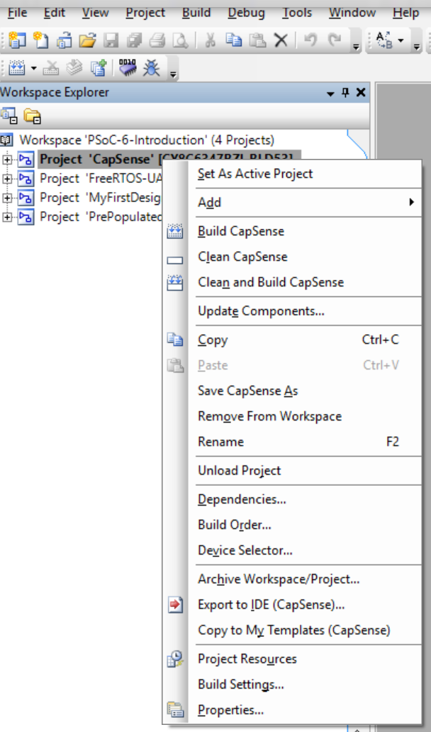
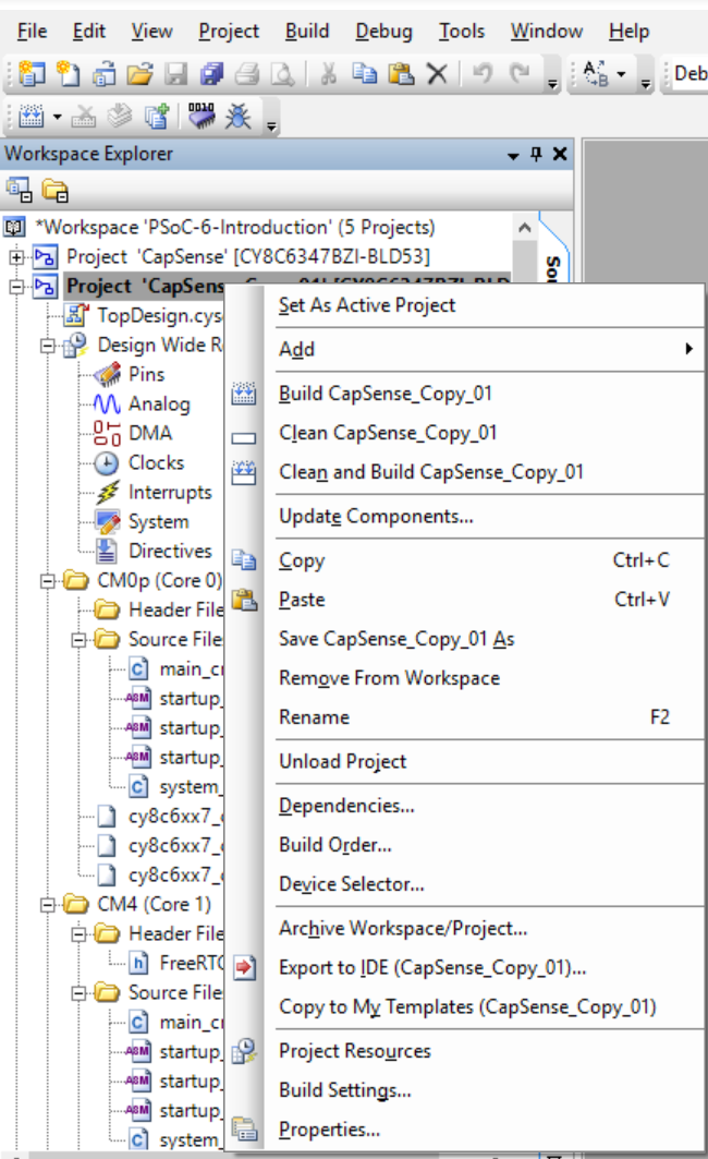
Hassane is all about reuse and he had copied the design of this section of his project from my article on using queues with FreeRTOS.  It looks like this.

  1. There is a task that manages the I2C and talks directly to the SCB hardware and the I2C devices
  2. There is a task that manages the OLED

ssd1306 oled display architecture

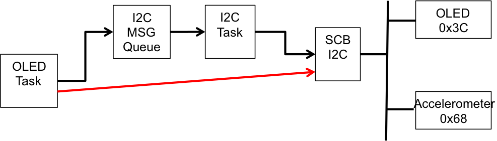
Originally the OLED task was talking directly to the I2C via the SCB (the red line on the picture).  Remember from the article on the U8G2 library, the hardware abstraction layer looks like this.  Basically it

  1. Sends an I2C Start at the start of the U8G2 transaction
  2. Sends an I2C Stop at the end of the tranaction
  3. Send the number of bytes called for.
uint8_t u8x8_I2C_HW(u8x8_t *u8x8, uint8_t msg, uint8_t arg_int, void *arg_ptr)
{
    uint8_t *data;
    switch(msg)
    {
        case U8X8_MSG_BYTE_SEND:            
            data = (uint8_t *)arg_ptr;
            while( arg_int > 0 )
            {
                Cy_SCB_I2C_MasterWriteByte(I2Cm1_HW, *data, I2C_TIMEOUT, &I2Cm1_context);
  	            data++;
	            arg_int--;
            }
        break;
      
        case U8X8_MSG_BYTE_START_TRANSFER:
            Cy_SCB_I2C_MasterSendStart(I2Cm1_HW, u8x8_GetI2CAddress(u8x8)>>1, CY_SCB_I2C_WRITE_XFER, I2C_TIMEOUT, &I2Cm1_context);
         break;
        
        case U8X8_MSG_BYTE_END_TRANSFER:
            Cy_SCB_I2C_MasterSendStop(I2Cm1_HW, I2C_TIMEOUT, &I2Cm1_context);
        break;
    
        default:
            return 0;
    }
    
    return 1;
}

The problem with this design is that it takes over the I2C hardware and requires exclusive control.  Moreover, it leaves you program hung while the transaction is happening.  To solve this problem, there are three options

  1. “Assign” the SCB block to the exclusive use of this task (makes it hard to share with other I2C devices)
  2. Create a mutex for the SCB.  This will work, but it will not allow the task to “queue” transactions and move on
  3. Create a task to manage the SCB with a queue (the option that Hassane chose)

The I2C message queue holds complete transactions.  Each transaction (which he called I2Cm_transaction_t) looks like this:

typedef enum I2Cm_transactionMethod {
    I2CM_READ,
    I2CM_WRITE
} I2Cm_transactionMethod_t;

typedef enum I2Cm_registerAddresType {
    I2CM_NONE, 
    I2CM_BIT8,
    I2CM_BIT16
} i2cm_registerAddressType_t;

typedef struct I2Cm_transaction {
    I2Cm_transactionMethod_t I2Cm_method;        // I2CM_READ or I2CM_WRITE
    uint8_t I2Cm_address;                        // The I2C Address of the slave
    i2cm_registerAddressType_t I2Cm_regType;     // I2CM_8BIT or I2CM_16BIT
    uint16_t I2Cm_register;                      // The register in the slave    
    uint8_t *I2Cm_bytes;                         // A pointer to the data to be written (or a place to save the data)
    uint32_t *I2Cm_bytesProcessed;               // A return value with the number of bytes written
    uint32_t I2Cm_byteNum;                       // How many bytes are in the request
    SemaphoreHandle_t I2Cm_doneSemaphore;        // If you want a semaphore flagging that the transaction is done 
} I2Cm_transaction_t;

In order to fix the the HAL you just sets up a transaction at the start of the task:

   memset(&OLEDtransaction,0,sizeof(OLEDtransaction));
	OLEDtransaction.I2Cm_method = I2CM_WRITE;
	OLEDtransaction.I2Cm_address = OLED_ADDRESS_1;
	OLEDtransaction.I2Cm_regType = I2CM_NONE;
	OLEDtransaction.I2Cm_bytes = buff;
	OLEDtransaction.I2Cm_bytesProcessed = &numProcessed;	
    OLEDtransaction.I2Cm_doneSemaphore = xSemaphoreCreateBinary();

Then queue up the bytes into a buffer, and flush the buffer when the “U8X8_MSG_BYTE_END_TRANSFER” message comes

uint8_t u8x8_I2C_HW(u8x8_t *u8x8, uint8_t msg, uint8_t arg_int, void *arg_ptr)
{
    uint8_t *data;
    switch(msg)
    {
        case U8X8_MSG_BYTE_SEND:        
            data = (uint8_t *)arg_ptr;
            while( arg_int > 0 )
            {
                buff[buffCount] = *data;
                buffCount += 1;
                CY_ASSERT(buffCount < BUFFSIZE);              
  	            data++;
	            arg_int--;
            }
        break;
 
        case U8X8_MSG_BYTE_START_TRANSFER:
            buffCount = 0;
         break;
        
        case U8X8_MSG_BYTE_END_TRANSFER:
	        OLEDtransaction.I2Cm_byteNum = buffCount;
            I2Cm1RunTransaction(&OLEDtransaction);
        break;
    
        default:
        return 0;
    }
    
    return 1;
}

SSD1306 OLED Display

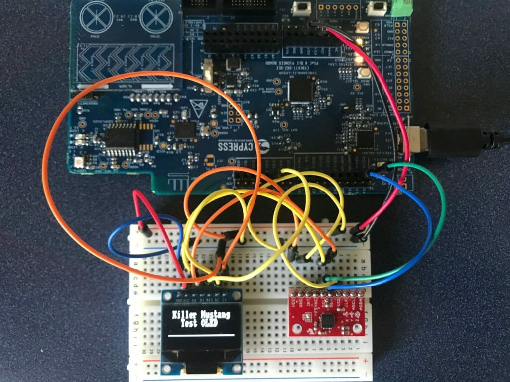
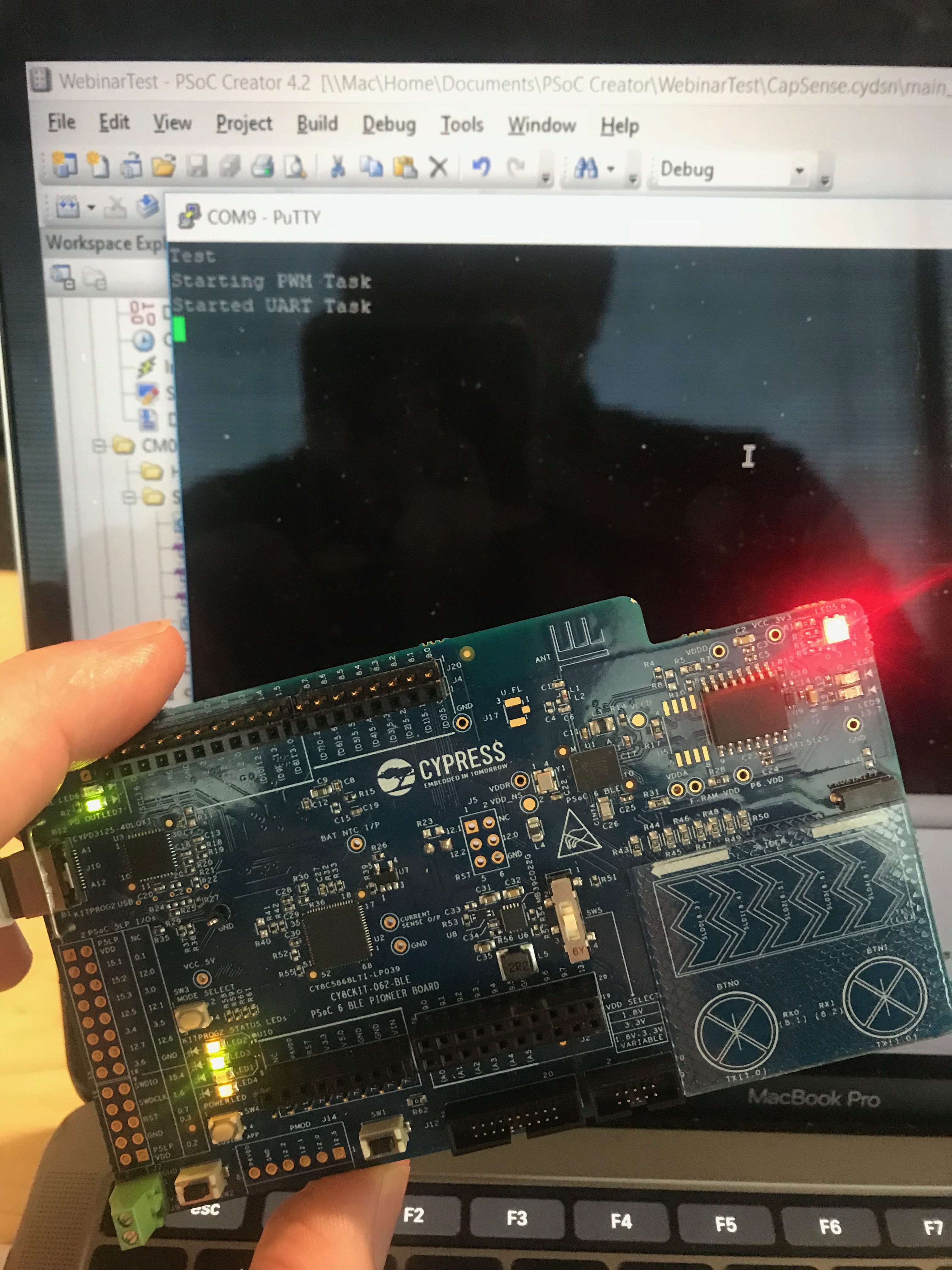
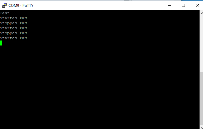
Now, the short block of test code works perfect:

    u8x8_Setup(&MyI2Cu8x8, u8x8_d_ssd1306_128x32_univision, u8x8_cad_ssd13xx_i2c, u8x8_I2C_HW, u8x8_gpio_and_delay_PSoC6);
        
    u8x8_InitDisplay(&MyI2Cu8x8);  
    u8x8_SetPowerSave(&MyI2Cu8x8,0);
    u8x8_ClearDisplay(&MyI2Cu8x8);
    u8x8_SetFont(&MyI2Cu8x8,u8x8_font_amstrad_cpc_extended_f);
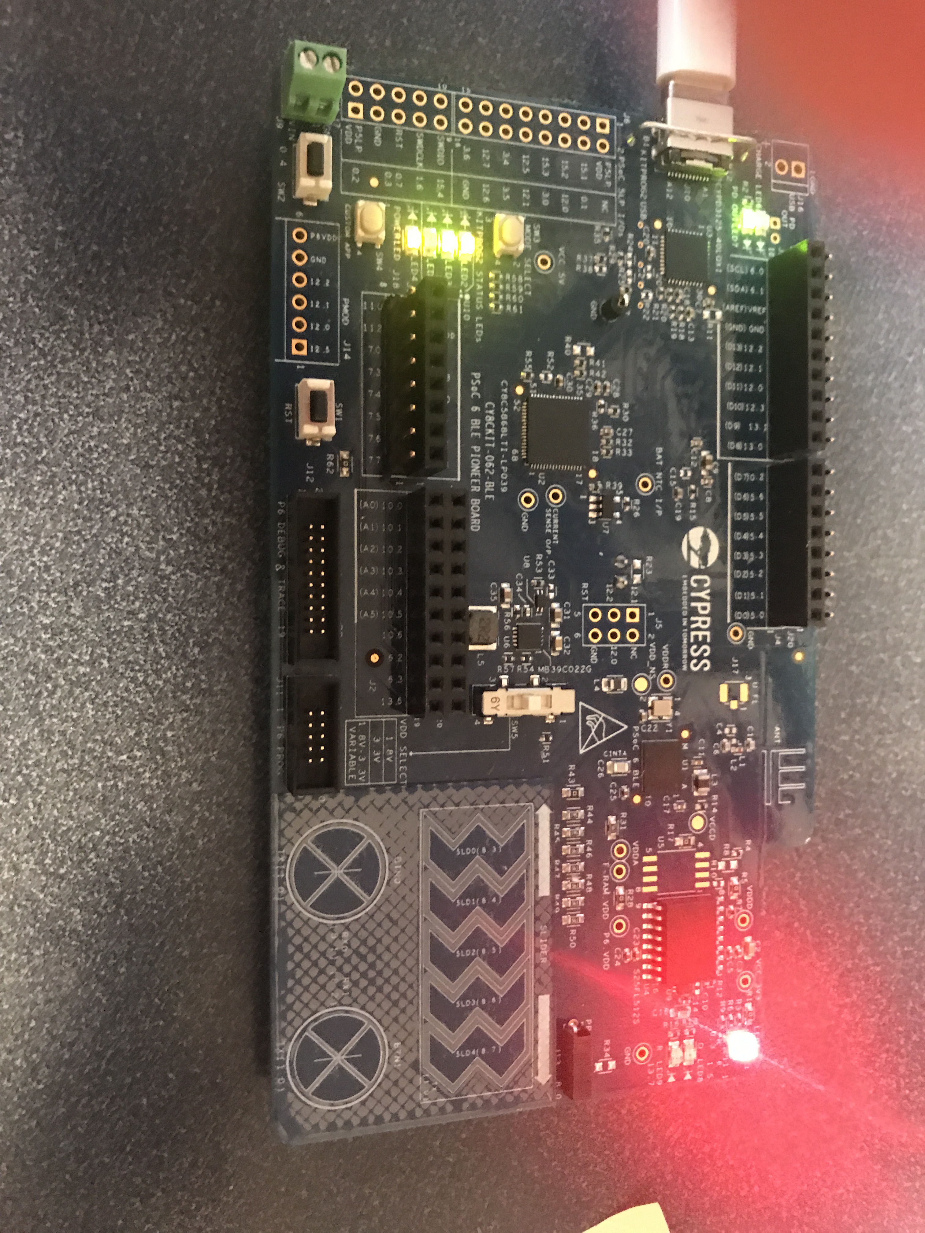
    u8x8_DrawString(&MyI2Cu8x8,0,0," Killer Mustang ");
    u8x8_DrawString(&MyI2Cu8x8,0,1,"   Test OLED    ");
    u8x8_DrawString(&MyI2Cu8x8,0,2,"________________");

And I get a nice output (I wonder what a “Killer Mustang” is?)

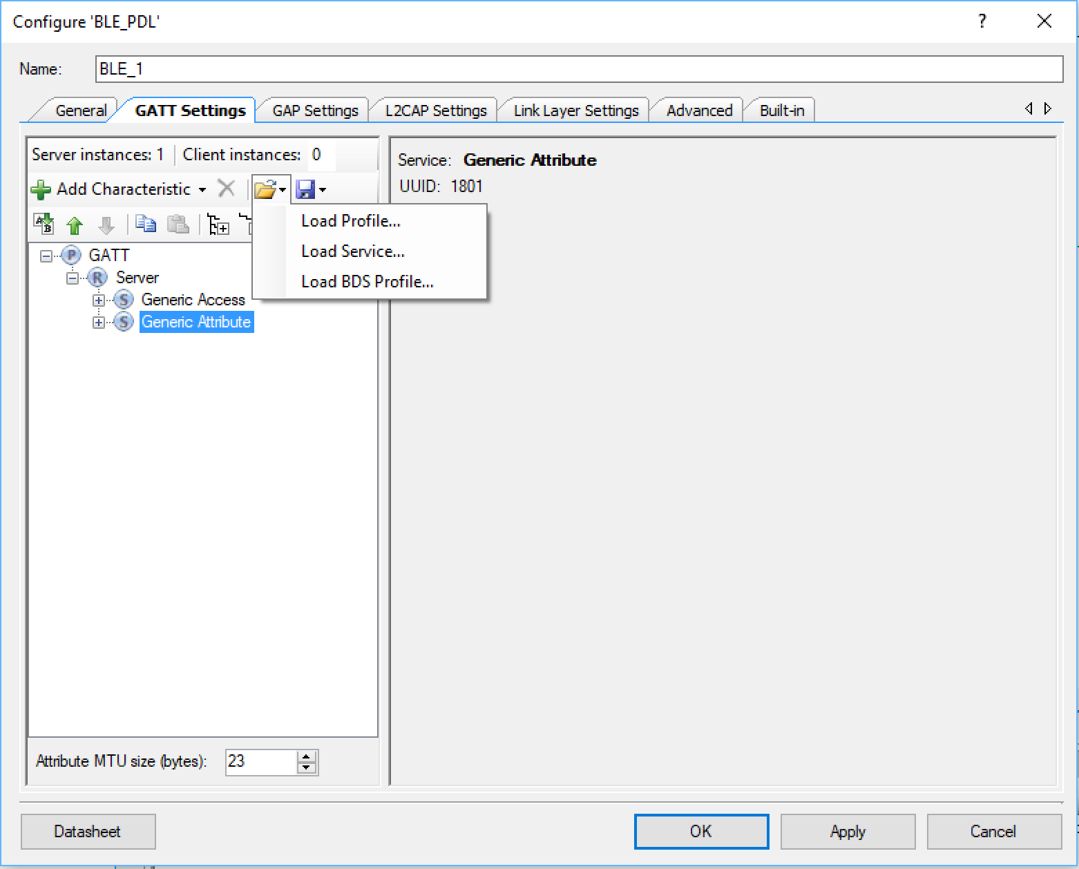
In the next article Ill talk about the SS1306 and a problem that I created for myself.

PSoC 6 Introduction – Behind the Scenes

Summary

As you might have noticed, last week I did a bunch of work creating a live streaming video series about PSoC 6.  You can find the recorded video here.  If you have been living under a bridge you might not know that PSoC 6 is the new Cypress PSoC.  It includes a dual ARM Cortex M4/M0+, a Bluetooth Low Energy 5.0 Radio, CapSense plus all of the other stuff that PSoC is known for.  The chip is super cool and has gotten everybody and their brother excited about the future.

PSoC 6 Introduction

# Title Comment
0 A Two Hour PSoC 6 Class An introduction to the PSoC 6 class with links to all of the documents
1 Resources Links to all of the Cypress PSoC 6 information including videos, application notes etc.
2 Your First Project Learn how to build a PSoC 6 project and program your CY8CKIT-062-BLE development kit
3 FreeRTOS and a Debugging UART Build a project using FreeRTOS including a debug console with the UART
4 CapSense Build a project using the Mutual Cap Buttons and Self Cap Slider
5 Bluetooth Low Energy Build a CapSense project using BLE and CySmart

Since I did the webinar several things have happened

  1. Lesson 4: I fixed an error in the stack size for FreeRTOS
  2. Lesson 5: The PSoC Creator BLE PDL has been upgraded to greatly simplify the notifyCapSense function

All of the projects are available at git@github.com:iotexpert/psoc-6-introduction.git or www.github.com/iotexpert/psoc-6-introduction

You will be seeing a bunch more from me using the CY8CKIT-062-BLE development kits.

PSoC 6 Webinar

Here are some behind the scenes pictures that were taken the day before and the day of the recording session.

In the studio on Wednesday night… why doesnt it work?

Getting Ready for the PSoC 6 Webinar

Yes, Mouser was sponsoring the event… thank you very much!

PSoC 6 and Mouser

Getting things setup the morning of the recording session.

The morning of the PSoC 6 Video Webinar

During the presentation (Im sure whatever I was saying was important)

Talking about PSoC 6

Some video taken from behind the scenes.

The Gospel of PSoC 6

The whole crew.  Thank you very much to Mouser and ON24.

The whole crew for the PSoC 6 Webinar

Lesson 5 – PSoC 6 Introduction: Bluetooth Low Energy

PSoC 6 Introduction

# Title Comment
0 A Two Hour PSoC 6 Class An introduction to the PSoC 6 class with links to all of the documents
1 Resources Links to all of the Cypress PSoC 6 information including videos, application notes etc.
2 Your First Project Learn how to build a PSoC 6 project and program your CY8CKIT-062-BLE development kit
3 FreeRTOS and a Debugging UART Build a project using FreeRTOS including a debug console with the UART
4 CapSense Build a project using the Mutual Cap Buttons and Self Cap Slider
5 Bluetooth Low Energy Build a CapSense project using BLE and CySmart

Since I did the webinar several things have happened

  1. Lesson 4: I fixed an error in the stack size for FreeRTOS
  2. Lesson 5: The PSoC Creator BLE PDL has been upgraded to greatly simplify the notifyCapSense function

All of the projects are available at git@github.com:iotexpert/psoc-6-introduction.git or www.github.com/iotexpert/psoc-6-introduction

Project Description

This project is a PSoC 6 BLE extension of the previous project with CapSense and UART.

The BLE will:

  • Advertise the device with the name “P6Intro” and as having the CapSense Service
  • Will allow one connection (with no security)
  • A BLE CapSense Service with the CapSense Slider characteristic as “notify”
  • When the CapSense slider updates it will send a notification to any connected device

The CapSense will (same as before)

  • BTN0 will set the intensity to 0%
  • BTN1 will set the intensity to 100%
  • CapSense slider will set the intensity (0-100) when touched

The UART will (same as before)

  • UART Key ‘0’ turn the LED to intensity = 0%
  • UART Key ‘1’ turn the LED to intensity = 100%
  • UART Key ‘5’ turn the LED to intensity = 50%
  • UART Key ‘?’ will printout help

How does it work?

This device will act as a GAP Peripheral with a GATT database server with the CapSense Service.  The PSoC 6 BLE component will allow you to split the BLE function onto the CM0+ (Controller) and the CM4 (Host and Profiles).  On the CM4 you will build an event handler which will act each time something happens in the Bluetooth world e.g. a connection, a disconnection, a read or write.

(same as previous project) You can control the intensity of an LED with a pulse width modulator and a high frequency input clock.  If the duty cycle is “small” then the intensity of the LED is low (meaning dim).  If the duty cycle is “big” then the intensity is “high”.  A 0% duty cycle will be off, a 50% duty cycle will be in the middle and 100% duty cycle will be all on.  To make this work I will set the input clock to 1 MHZ and the PWM Period to 100.  The PWM Compare value will then be set between 0 and 100 to represent brightness in percent.

(same as previous project) The Cypress CapSense block has two sensing modes, mutual capacitance and self-capacitance.   The CY8CKIT-062-BLE has two Mutual Capacitance buttons and a 5-Segment Self or Mutual Capacitance Slider.

The project will have four tasks

  • BLE – Will act as a BLE GATT Peripheral that advertises the CapSense Service with the CapSense Slider.  The value of the slider will ‘Notify’
  • UART – Read data from the keyboard and send messages to the PWM Task
  • CapSense – Read finger positions from the slider and buttons and send messages to the PWM Task
  • PWM – Will have an input queue, when a integer message is received it will set the PWM compare value to the integer received (0 >= msg <= 100)

How am I going to do it?

  1. Copy, Paste and Rename the CapSense UART Project
  2. Add and Configure the BLE Component
  3. Fix the Interrupts
  4. Update the main_cm0p. c to run the BLE radio
  5. Add three global variables to main_cm4.c
  6. Create a new task to process the BLE
  7. Create an Event Handler
  8. Make a Function to Send Notifications
  9. Update the capSenseTask to Send Values
  10. Add the bleTask to main function in main_cm4.c
  11. Program and Test

Copy, Paste and Rename the CapSense UART Project

Right click on the PSoC-6-Introdution and Paste

Right click and rename the project to be CapSense_BLE

When is asks you to rename… do it

It should look like this now.

Add and Configure the BLE Component

Go to the Component Catalog and find the Bluetooth Low Energy component and drag/drop it into your design schematic.

Configure the component to be a “Dual Core …” and set the  number of connections to 1.

Add the Capsense service to your server by clicking “Load Service…”

And selecting the “CapSense.service” file.  I created this file to have the right UUIDs and characteristics.

You can now look at the CapSense Slider service and the CapSlider characteristic

Set the name of our peripheral in the “GAP Settings”.  In this case I will call it P6INTRO.

Configure the advertising settings to advertise the name of the device and the CapSense Service.

Fix the Interrupts

Almost all of the interrupt sources in the PSoC 6 can be connected to one or both of the Cortex cores.  I think that you are probably crazy to attach it to both.  In this case the BLE interrupt needs to be connected to the “ARM CM0+”

Update main_cm0p. c to Run the BLE Radio Controller

#include <project.h>
int main(void)
{
    __enable_irq(); /* Enable global interrupts. */
  
   
    Cy_BLE_Start(0);
    
    /* Enable CM4.  CY_CORTEX_M4_APPL_ADDR must be updated if CM4 memory layout is changed. */
    Cy_SysEnableCM4(CY_CORTEX_M4_APPL_ADDR); 
    

    for(;;)
    {
        Cy_BLE_ProcessEvents();
    }
}

Add three global variables to main_cm4.c

The BLE Task will have a queue that the CapSense will use to send out changes in the CapSense Slider.

QueueHandle_t bleQueueHandle;
int connected=0;
int notify=0;

Create a new task to process the BLE

The. task will just start up the BLE processing on the CM4.  Then it will cause the BLE event manager to run.  If a new value of the CapSense slider is set, it will send out a notification using the “notifyCapSense” function

// bleTask handles the BLE connection (or not).. if the user connects and turns on
// notifications then it sends out new values of the CapSense slider
void bleTask(void *arg)
{
    (void)arg;   
    uint32_t msg;
    
    printf("Starting BLE Task\r\n");
    bleQueueHandle = xQueueCreate(1,sizeof(uint32_t));
    Cy_BLE_Start(customEventHandler);
    
    for(;;)
    {
        Cy_BLE_ProcessEvents();
        
        // CapSense task will put CapSense slider values in the bleQueueHandle
        if(xQueueReceive(bleQueueHandle,&msg,0) == pdTRUE)
            notifyCapSense((uint8_t)msg);
       
        taskYIELD();
    }
}

Create an Event Handler

You will need a task to handle the BLE processing on the CM4.  Each time a Bluetooth event occurs you will need to do “something”

// This event handler is called by BLE
void customEventHandler(uint32_t event, void *eventParameter)
{
     cy_stc_ble_gatts_write_cmd_req_param_t   *writeReqParameter;   

    switch (event)
    {
        case CY_BLE_EVT_STACK_ON:
        case CY_BLE_EVT_GAP_DEVICE_DISCONNECTED: // Central disconnects
            Cy_BLE_GAPP_StartAdvertisement(CY_BLE_ADVERTISING_FAST,CY_BLE_PERIPHERAL_CONFIGURATION_0_INDEX);
            connected = 0;
            notify=0;
        break;

        case CY_BLE_EVT_GATT_CONNECT_IND: // A Central connection is made
            connected = 1;
        break;
        
        case CY_BLE_EVT_GATTS_WRITE_REQ:
            writeReqParameter = (cy_stc_ble_gatts_write_cmd_req_param_t *)eventParameter;

            if(CY_BLE_CAPSENSE_CAPSLIDER_CLIENT_CHARACTERISTIC_CONFIGURATION_DESC_HANDLE ==  writeReqParameter->handleValPair.attrHandle)
                notify = writeReqParameter->handleValPair.value.val[0];
              
            Cy_BLE_GATTS_WriteRsp(writeReqParameter->connHandle);
        break;

        default: // Ignore all other events
        break;
    }
}

Make a Function to Send Notifications

// This function is run inside BLE Task and sends notification if you are connected and notifications are on
void notifyCapSense(uint8_t capValue)
{    
    if(!(connected && notify))
        return;
    
    cy_stc_ble_gatts_handle_value_ntf_t v1;
    v1.connHandle = cy_ble_connHandle[0];
    v1.handleValPair.attrHandle = CY_BLE_CAPSENSE_CAPSLIDER_CHAR_HANDLE;
    v1.handleValPair.value.len = 1;
    v1.handleValPair.value.val = &capValue;
    
    Cy_BLE_GATTS_Notification(&v1);
        
}

EDIT!!!!

If you look at the source code at GitHub you will find that I removed the variables “connected” and “notify” and I changed the notifyCapSense function.  This was done because the BLE PDL implementation was greatly improved and simplified. The new function iterates through the connections and sends the notification to all of them.  This was done to handle multiple connections.

// This function is run inside BLE Task and sends notification if you are connected and notifications are on
void notifyCapSense(uint8_t capValue)
{    
   
    unsigned int index;
    
    printf("Sending CapSense %d\r\n",capValue);
   
    cy_stc_ble_gatt_handle_value_pair_t handleValuePair;
    handleValuePair.attrHandle = CY_BLE_CAPSENSE_CAPSLIDER_CHAR_HANDLE;
    handleValuePair.value.val = &capValue;
    handleValuePair.value.len = 1;
    
    Cy_BLE_GATTS_WriteAttributeValueLocal(&handleValuePair);
   
    /* Iterate and send notiication to all the connected devices that are ready to receive notification */
    for(index = 0; index <CY_BLE_CONN_COUNT; index++)
    {     
        Cy_BLE_GATTS_SendNotification(&cy_ble_connHandle[index], &handleValuePair);
    }
        
}

Update the capSenseTask to Send Values

Inside of the capsenseTask you need to send new values of the slider to the BLE task via the Queue.  Meaning the BLE task needs to send out notifications, but it can only do that if the capsenseTask notifies it of changes.

sliderPos=CapSense_GetCentroidPos(CapSense_LINEARSLIDER0_WDGT_ID);
            if(sliderPos<0xFFFF) // If they are touching the slider then send the %
            {
                msg = sliderPos;
                xQueueSend(pwmQueueHandle,&msg,0); // Send message to PWM - change brightness
                xQueueSend(bleQueueHandle,&msg,0); // Send message to BLE
            }

Add the bleTask to main function in main_cm4.c

In the main function you need to start the BLE Task.

xTaskCreate( bleTask, "BLE Task",4096,0,3,0);

Program and Test

To test this project I will run the CySmart iOS App.  First, you can see all of the devices that are advertising

CySmart

Scroll left (or right) to find the “CapSense Slider”

When you see it, Press on the CapSense Slider Icon

Then put your finger on the slider and you should see it change

Here is a picture of the whole system.

PSoC 6 BLE CapSense & CySmart

Lesson 4 – PSoC 6 Introduction: CapSense

PSoC 6 Introduction

# Title Comment
0 A Two Hour PSoC 6 Class An introduction to the PSoC 6 class with links to all of the documents
1 Resources Links to all of the Cypress PSoC 6 information including videos, application notes etc.
2 Your First Project Learn how to build a PSoC 6 project and program your CY8CKIT-062-BLE development kit
3 FreeRTOS and a Debugging UART Build a project using FreeRTOS including a debug console with the UART
4 CapSense Build a project using the Mutual Cap Buttons and Self Cap Slider
5 Bluetooth Low Energy Build a CapSense project using BLE and CySmart

Since I did the webinar several things have happened

  1. Lesson 4: I fixed an error in the stack size for FreeRTOS
  2. Lesson 5: The PSoC Creator BLE PDL has been upgraded to greatly simplify the notifyCapSense function

All of the projects are available at git@github.com:iotexpert/psoc-6-introduction.git or www.github.com/iotexpert/psoc-6-introduction

Project Description

This project is a demonstration of a PSoC 6 running an RTOS using CapSense and the UART to control the intensity of the Red LED with a Pulse Width Modulator (PWM)

The CapSense will:

  • BTN0 will set the intensity to 0%
  • BTN1 will set the intensity to 100%
  • CapSense slider will set the intensity (0-100) when touched

The UART will:

  • UART Key ‘0’ turn the LED to intensity = 0%
  • UART Key ‘1’ turn the LED to intensity = 100%
  • UART Key ‘5’ turn the LED to intensity = 50%
  • UART Key ‘?’ will printout help

How does it work?

You can control the intensity of an LED with a pulse width modulator and a high frequency input clock.  If the duty cycle is “small” then the intensity of the LED is low (meaning dim).  If the duty cycle is “big” then the intensity is “high”.  A 0% duty cycle will be off, a 50% duty cycle will be in the middle and 100% duty cycle will be all on.  To make this work I will set the input clock to 1 MHz and the PWM Period to 100.  The PWM Compare value will then be set between 0 and 100 to represent brightness in percent.

The Cypress CapSense block has two sensing modes, mutual capacitance and self capacitance.   The CY8CKIT-062-BLE has two Mutual Capacitance buttons and a 5 segment Self or Mutual Capacitance Slider.

The project will have three tasks

  • UART – Read data from the keyboard and send messages to the PWM Task
  • CapSense – Read finger positions from the slider and buttons and send messages to the PWM Task
  • PWM – Will have an input queue, when a integer message is received it will set the PWM compare value to the integer received (0 >= msg <= 100)

How am I going to do it?

  1. Create a new project by copy/paste the FreeRTOS-UART Project
  2. Configure Schematic for Higher Frequency Clock and Change PWM Settings
  3. Add a new PWM task and modify the UART
  4. Program and Test
  5. Edit the FreeRTOS.h and make a bigger heap
  6. Add the CapSense Buttons to the Schematic and Set the Pins
  7. Add the capsenseTask
  8. Program and Test
  9. Add the CapSense Slider to the Schematic and Set the Pins
  10. Update the capsenseTask
  11. Program and Test

Create a new Project by Copy/Paste of FreeRTOS-UART Project

Right click on the FreeRTOS-UART Project then select “Copy”

PSoC 6 Create New Project - Copy

Then right click on the Workspace and select “Paste”

PSoC 6 Create New Project - Paste


Right click on “FreeRTOS-UART-Copy01)” and rename it to “CapSense”

PSoC 6 Create New Project - Rename

Click “Rename” (all of these files will be regenerated so it doesn’t really matter)

PSoC 6 Create New Project - Rename

Close all windows by right clicking “Close All But This” on the start tab

PSoC Creator Close All Windows

Configure Schematic for Higher Frequency Clock and Change PWM Settings

If you blink the LED fast enough, you will not be able to see the “Blink” it will just appear to be bright or dim based on the duty cycle.  Start by changing the clock to 1 MHz.

PSoC 6 Update Clock

Double click on the PWM_1

PSoC 6 Update TCPWM

Fix the Period to be 100 and the compare to be 50

PSoC 6 Update TCPWM

The LED on the CY8CKIT-062-BLE is active low which means that when it is 0 the LED is on.  I want the opposite behavior so I can configure the PWM output to be inverted on the advanced tab.  Click the button next to “Invert PWM Output”

PSoC 6 Update TCPWM Advanced

Add a new PWM Task and Modify the UART Task

Next, I will create the pwmTask function.  It will simply wait for someone to send a message to the pwmQueue.  The message is simply a uint32_t that represents the PWM compare value … aka the percent intensity of the LED.  When it gets the value, it will update the hardware.

Edit: In the comments below you can see that Charles asked that I clarify where these functions should go.  When I did this, I put them basically at the top of the file… just under the #includes.   The only thing that really matters is that they need to be put before they are used so that the compiler knows the function prototypes.  If you put them after they are used then you need to make forward declarations.

#include "queue.h"
QueueHandle_t pwmQueueHandle; 

// This task controls the PWM
void pwmTask(void *arg)
{
    (void)arg;
    
    uint32_t msg;
    
    printf("Starting PWM Task\r\n");
    pwmQueueHandle = xQueueCreate(1,sizeof(uint32_t));
   
    while(1)
    {
        xQueueReceive(pwmQueueHandle,&msg,portMAX_DELAY);
        Cy_TCPWM_PWM_SetCompare0(PWM_1_HW,PWM_1_CNT_NUM,msg);
   }
}

In the main function you need to start the pwmTask

xTaskCreate(pwmTask,"PWM Task",configMINIMAL_STACK_SIZE*8,0,3,0);

Next, I will update the uartTask

  • To not getchar’s unless there is something in the RX buffer of the UART (line 13).
  • Create a message aka a uin32_t based on the key pressed and send it with xQueueSend
  • If there was nothing there then taskYIELD to one of the other tasks (line 35)
// uartTask - the function which handles input from the UART
void uartTask(void *arg)
{
    (void)arg;
    
    char c;
    uint32_t msg;

    printf("Started UART Task\r\n");
    setvbuf(stdin,0,_IONBF,0);
	while(1)
	{
		if(Cy_SCB_UART_GetNumInRxFifo(UART_1_HW))
		{
		    c = getchar();
    		switch(c)
	    	{
		    	case '0': // send the stop message
			    	msg = 0;
		    		xQueueSend(pwmQueueHandle,&msg,portMAX_DELAY);               
		    	break;
		    	case '1': // Send the start message
		    		msg = 100;
		    		xQueueSend(pwmQueueHandle,&msg,portMAX_DELAY);
		    	break;
			    case '5':
				    msg = 50;
				    xQueueSend(pwmQueueHandle,&msg,portMAX_DELAY);
			    break;
			    case '?': // Print Help 
				    printf("s - stop PWM\r\nS - start PWM\r\n");
			    break;
		    }
		}
		taskYIELD();
    }
}

Program and Test

PSoC 6 Test PWM

Edit the FreeRTOS.h and make a bigger heap

The CapSense task is going to take more heap space that is currently allocated for FreeRTOS.  To fix this I need to edit the FreeRTOS.h and change the heap size to 48K (which I picked out of the air)

#define configTOTAL_HEAP_SIZE                   (48*1024)

Add the CapSense Buttons to the Schematic and Set the Pins

In order to add CapSense to the design, you find the CapSense component in the Component Catalog. Then you drag it into your schematic.

PSoC 6 Add CapSense Component

The next thing to do is configure the CapSense block.  I start by re-naming it to “CapSense”.  Then I click on the plus and add two “Button”s to the design.

PSoC 6 Add CapSense Buttons

Then I change the configuration to “CSX (Mutual-cap).

PSoC 6 Setup Mutual CapSense

On the CY8CKIT-062-BLE, there is a shared transmit line. This saves 1 pin.  You need to tell the CapSense component that you are using a shared Tx.  To do this click on Advanced -> Widget Details.  Then pick “Button1_tx” and set the Sensor Connection / Ganging to “Button0_Tx”

PSoC 6 Setup CapSense Tx

Once the CapSense is configured you need to Set the Pins.

PSoC 6 Fix Pins

Next you run “Generate Application” which will let PSoC Creator place and route the design plus bring in all of the required drivers.

Add the capsenseTask

Now create a new task function called capsenseTask it will

  • Use 4 variables to hold the previous and current state of the buttons (line 81-84)
  • Start the CapSense Block (line 88)
  • Start CapSense Scanning (line 89)
  • If the CapSense hardware is not busy then you can talk to it. (line 93)
  • Start by turning the raw data into useable information (line 96)
  • Read the state of the buttons (line 98-99)
  • If the button state has changed, then send a message to the PWM Task (line 101-110)
  • Save the state of the buttons (line 111-112)
  • Update the baseline information (line 114)
  • Start Scanning again (line 115)
  • If the CapSense block is busy then yield to the other tasks (line 118)
// capsenseTask
// Read buttons and slider using CapSense and send messages to pwmQueue
void capsenseTask(void *arg)
{
    (void)arg;
    
    uint32_t msg;
    
    int b0prev=0;
    int b1prev=0;
    int b0current=0;
    int b1current=0;
    int sliderPos;
    
    printf("Starting CapSense Task\r\n");
    
    CapSense_Start();
    CapSense_ScanAllWidgets();
        
    for(;;)
    {
        if(!CapSense_IsBusy())
        {
            CapSense_ProcessAllWidgets();
/*
            sliderPos=CapSense_GetCentroidPos(CapSense_LINEARSLIDER0_WDGT_ID);
            if(sliderPos<0xFFFF) // If they are touching the slider then send the %
            {
                msg = sliderPos;
                xQueueSend(pwmQueueHandle,&msg,portMAX_DELAY);
            }
*/
            b0current = CapSense_IsWidgetActive(CapSense_BUTTON0_WDGT_ID);
            b1current = CapSense_IsWidgetActive(CapSense_BUTTON1_WDGT_ID); 
            
            if(b0current && b0prev == 0) // If they pressed btn0
            {
                msg = 0; 
                xQueueSend(pwmQueueHandle,&msg,portMAX_DELAY);
            }
            if( b1current && b1prev == 0) // If they pressed btn0
            {
               msg = 100;
               xQueueSend(pwmQueueHandle,&msg,portMAX_DELAY);  
            }
            b0prev = b0current;
            b1prev = b1current;
               
            CapSense_UpdateAllBaselines();
            CapSense_ScanAllWidgets();
        }
        else
            taskYIELD();
            
    }    
}

And start the capSense task in main.

xTaskCreate( capsenseTask, "CapSense Task",2048*2,0,3,0);

Program and Test

PSoC 6 Test CapSense Buttons

Add the CapSense Slider to the Schematic and Set the Pins

To make the slider work you need to add a LinearSlider widget by pressing the “+” and selecting LinearSlider

PSoC 6 Add CapSense Slider

Once you have added the LinearSlider you need to set the pins for the new CapSense Slider

PSoC 6 Fix CapSense Slider Pins

Update the capsenseTask to Include the Slider

The changes are small to make the LinearSlider work.  You just need to

  1. Read the position of the slider (line 99)
  2. The slider will be 0xFFFF if there is no touch… in which case ignore it (line 100)
  3. If you got a touch, then make that a message and set it to the PWM (line 102-103)
          sliderPos=CapSense_GetCentroidPos(CapSense_LINEARSLIDER0_WDGT_ID);
            if(sliderPos<0xFFFF) // If they are touching the slider then send the %
            {
                msg = sliderPos;
                xQueueSend(pwmQueueHandle,&msg,portMAX_DELAY);
            }

Program and Test

PSoC 6 CapSense Slider

Lesson 3 – PSoC 6 Introduction: FreeRTOS and a Debugging UART

PSoC 6 Introduction

# Title Comment
0 A Two Hour PSoC 6 Class An introduction to the PSoC 6 class with links to all of the documents
1 Resources Links to all of the Cypress PSoC 6 information including videos, application notes etc.
2 Your First Project Learn how to build a PSoC 6 project and program your CY8CKIT-062-BLE development kit
3 FreeRTOS and a Debugging UART Build a project using FreeRTOS including a debug console with the UART
4 CapSense Build a project using the Mutual Cap Buttons and Self Cap Slider
5 Bluetooth Low Energy Build a CapSense project using BLE and CySmart

Since I did the webinar several things have happened

  1. Lesson 4: I fixed an error in the stack size for FreeRTOS
  2. Lesson 5: The PSoC Creator BLE PDL has been upgraded to greatly simplify the notifyCapSense function

All of the projects are available at git@github.com:iotexpert/psoc-6-introduction.git or www.github.com/iotexpert/psoc-6-introduction

Project Description

This project will show you how to build a PSoC 6 project that is running FreeRTOS and printing information to the debugging UART

How does it work?

The PSoC 6 is a very capable, fast dual Coretex-M MCU.  In order to manage your design complexity that can be attacked with this chip, we gave you the ability to use a Real Time Operating System – FreeRTOS.  With a few simple clicks it will startup for you.

The CY8CKIT-062-BLE has a KitProg-2 Debugger/Programmer on board.  In addition to Program/Debug it can also serve as a USB <–> UART bridge which will allow you to open a terminal program on your PC to do Input/Output with a UART in the PSoC 6.

How am I going to do it?

  1. Copy “MyFirstDesign” to Start a New Project
  2. Modify the Build Settings to add Debug Printing and FreeRTOS
  3. Add the UART to the Schematic and Assign the Pins
  4. Create the UART Test Firmware
  5. Program and Test the Debug UART
  6. Modify firmware for FreeRTOS
  7. Program and Test
  8. A Tour of PDL for the TCPWM

Copy “MyFirstDesign” to Start a New Project

Right click on “MyFirstDesign” and select “Copy”

PSoC Creator Copy Project

Then right click on the workspace and select “Paste”

PSoC Creator Copy/Paste

Then right click on “MyFirstDesign_Copy_01” and select rename.  Then type in a reasonable name like “FreeRTOS-UART”

PSoC Creator Copy / Paste

PSoC Creator will ask you about some files.  Just click “Rename”

PSoC Creator Rename

Now you will have three projects in your workspace.  I typically click “Program” which will build the copied project and program the development kit… just to make sure that stuff still works.

PSoC Creator Workspace

Modify the build settings to add debug printing and FreeRTOS

You can build massively complex systems with PSoC 6.  In order to help manage that complexity I like to turn on debug printing so that “printf” works.  I also like to use a Real Time Operating System (FreeRTOS).  PSoC Creator has both of these things built in.  We called the printf functionality “Retarget I/O” because you need to “target” the Input / Output of the printf … aka STDIN and STDOUT to a peripheral in the PSoC.  The best peripheral to use for printf is the UART that is attached to your computer via kitprog2.

To add printf and FreeRTOS to your project you need to: Right click on the project and select “Build Settings…”

PSoC Creator Modify Build Settings

Click on the Peripheral Driver Library and then select “FreeRTOS” and “Memory Management heap_4”.  Then select “Retarget I/O”.  When you build your project this will cause PSoC Creator to add both of these to your project.

PSoC Creator Build Settings FreeRTOS

Select Build->Generate Application and notice that PSoC Creator added a number of files to your project including the FreeRTOS, stdio_user.c/.h and retarget_io

PSoC Creator retarget_io.c

Add the UART to the Schematic and Assign the Pins

In order to printf, getchar and putchar  you need to attach c standard library stdin and stdout to “something”.  The best “something” is the UART that is attached to the KitProg2 which is attached to your computer.  Then you can open a terminal program (like Putty) and read and write to the PSoC.

So, to do this you need to add a UART to your design schematic from the component catalog.  In the picture below I just typed “uart” in the search box.

PSoC Creator Debug UART

What pins on the PSoC 6 BLE is the UART attached to?  Well… if you turn over your CY8CKIT-062-BLE you will find a little map that show that the PSoC 6 BLE UART is attached to the PSoC 5LP UART.  The PSoC 5LP is programmed with the KitProg2 firmware.

PSoC 6 CY8CKIT-062-BLE

To attach those pins in your firmware you just double click on the “Pins” tab in the DWR.  Then you can select “Port” for the UART RX and TX.  Look at the picture below.

PSoC 6 PSoC Creator Pin Settings

Now that I have all of that done, I run “Build->Generate Application” to get all of the new settings into my project.

Create the UART Test Firmware

The next step in making the printf work is to “retarget” it to the UART we just put in the schematic.  Open “stdio_user.h” and add “include <project.h>” (line 130) and change IO_STDOUT_UART and IO_STDIN_UART to be UART_1_HW.  The name “UART_1” on lines 136-137

#include <project.h>
#include "cy_device_headers.h"

/* Must remain uncommented to use this utility */
#define IO_STDOUT_ENABLE
#define IO_STDIN_ENABLE
#define IO_STDOUT_UART      UART_1_HW
#define IO_STDIN_UART       UART_1_HW

Now edit your main_cm4.c to:

  • Turn on the UART with UART_1_Start() on line
  • Then a couple of printfs lines 24-25

Note that “\033[2J\033[H” is just a VT100 escape sequence for clear screen and go home.

#include "project.h"
#include <stdio.h>

int main(void)
{
    __enable_irq(); /* Enable global interrupts. */

    /* Place your initialization/startup code here (e.g. MyInst_Start()) */

    PWM_1_Start();
    UART_1_Start();
    
    printf("3[2J3[H"); // Clear Screen
    printf("Test\r\n");
    
    
    for(;;)
    {
        /* Place your application code here. */
    }
}

Program and Test the Debug UART

You need to figure out which com port that the KitProg2 is attached to.  To do this run the device manager by pressing the “windows” button then typing “device manger”

Device Manager

Click on ports.  Then you can see that the programmer is “KitProg2” and that the UART is attached to COM9 (everyone will have a different number)

Device Manager

Run Putty (or  your favorite terminal program)

Putty

Press the program button on PSoC Creator and you should see your test print

Putty PSoC 6 UART

Modify firmware for FreeRTOS

When I look out the output window from the previous step you can see that there is a warning message from FreeRTOS.  Lets fix that warning (by deleting line 83).  While we are at it, lets change the heap size to 48K (48*1024)

Now lets turn on FreeRTOS. Double click on main_cm4.c to open it in the code editor.

Modify FreeRTOS Firmware

Add the following firmware to your project.

The uartTask is function that FreeRTOS uses to create a Task.  This task will control the uart. (which is amazingly enough why I named it uartTask)

  • The function call “setvbuff” turns of buffering on stdin… which means every character will immediately come through to your program
  • getchar just gets a character from the terminal
  • the ‘s’ and ‘S’ will start and stop the PWM (more to follow)

In main I

  • Create a task for the uartTask (line 56)
  • Start FreeRTOS (line 57)
/* ========================================
 *
 * Copyright YOUR COMPANY, THE YEAR
 * All Rights Reserved
 * UNPUBLISHED, LICENSED SOFTWARE.
 *
 * CONFIDENTIAL AND PROPRIETARY INFORMATION
 * WHICH IS THE PROPERTY OF your company.
 *
 * ========================================
*/
#include "project.h"
#include <stdio.h>
#include "FreeRTOS.h"
#include "task.h"

// uartTask - the function which handles input from the UART
void uartTask(void *arg)
{
    (void)arg;
    char c;
    setvbuf(stdin,0,_IONBF,0);
    while(1)
    {
        c = getchar();
        switch(c)
        {
            case 's': // Stop the PWM
                printf("Stopped PWM\r\n");
                Cy_TCPWM_PWM_Disable(PWM_1_HW,PWM_1_CNT_NUM);
                
            break;
            case 'S': // Start the PWM
                printf("Started PWM\r\n");
                Cy_TCPWM_PWM_Enable(PWM_1_HW,PWM_1_CNT_NUM);
                Cy_TCPWM_TriggerStart(PWM_1_HW, PWM_1_CNT_MASK);
            break;
        }
    }
}


int main(void)
{
    __enable_irq(); /* Enable global interrupts. */

    /* Place your initialization/startup code here (e.g. MyInst_Start()) */

    PWM_1_Start();
    UART_1_Start();
    
    printf("3[2J3[H"); // VT100 Clear Screen
    printf("Test\r\n");
 
    // Mask a FreeRTOS Task called uartTask
    xTaskCreate(uartTask,"UART Task",configMINIMAL_STACK_SIZE,0,3,0);
    vTaskStartScheduler();  // Will never return
    
    for(;;) // It will never get here
    {
    }
}

How did I figure out how to start/stop the PWM?  To find the documentation for “PDL” aka the Peripheral Driver Library, you can right click on the component in the schematic and select “Open PDL Documentation”

PSoC 6 TCPWM

Or you can open “Help –> Documentation –> Peripheral Driver Library”

PSoC Creator Help

In the documentation I can see all kind of functions, including “Cy_TCPWM_PWM_Disable”

PSoC 6 PDL

Program and Test

PSoC 6 FreeRTOS Test

A Tour of PDL for the TCPWM

How did I figure out that the TCPWM_Type *base should be “UART_1_HW”?  ….. well …. You might ask yourself, “What does PWM_1_Start()” do?  It just calls PDL start function.  OK… so what does that do?  To find out you can right click on the “PWM_1_Start” function and select “Go To Definition” which will take you to the source code.

PSoC 6 Tour of PDL

You will end up in a file called “PWM_1.c”.  This file was created for you automatically by PSoC Creator.   This function is really simple.

  • If it has never been initialized then it calls init (lines 15-19)
  • Then it enables the TCPWM (line 22)
  • Then if there not an external pin on the PWM, then it causes a software trigger (line 25)
/*******************************************************************************
* Function Name: PWM_1_Start
****************************************************************************//**
*
*  Calls the PWM_1_Init() when called the first time and enables 
*  the PWM_1. For subsequent calls the configuration is left 
*  unchanged and the component is just enabled.
*
* \globalvars
*  \ref PWM_1_initVar
*
*******************************************************************************/
void PWM_1_Start(void)
{
    if (0U == PWM_1_initVar)
    {
        (void) Cy_TCPWM_PWM_Init(PWM_1_HW, PWM_1_CNT_NUM, &PWM_1_config);

        PWM_1_initVar = 1U;
    }

    Cy_TCPWM_Enable_Multiple(PWM_1_HW, PWM_1_CNT_MASK);
    
    #if (PWM_1_INPUT_DISABLED == 7UL)
        Cy_TCPWM_TriggerStart(PWM_1_HW, PWM_1_CNT_MASK);
    #endif /* (PWM_1_INPUT_DISABLED == 7UL) */    
}

So, you might ask yourself what is “PWM_1_HW”?  Well this is just the base address of the registers for the PWM_1.  Lets follow that.  Right click on it and go to definition.

PSoC 6 PDL

This will take you to PWM_1.h and you will see PWM_1_HW is setup as PWM_1_TCPWM_HW.  What is that?  Well do the right click thing again and find out.

/***************************************
*           API Constants
***************************************/

/**
* \addtogroup group_macros
* @{
*/
/** This is a ptr to the base address of the TCPWM instance */
#define PWM_1_HW                 (PWM_1_TCPWM__HW)

/** This is a ptr to the base address of the TCPWM CNT instance */
#define PWM_1_CNT_HW             (PWM_1_TCPWM__CNT_HW)

/** This is the counter instance number in the selected TCPWM */
#define PWM_1_CNT_NUM            (PWM_1_TCPWM__CNT_IDX)

/** This is the bit field representing the counter instance in the selected TCPWM */
#define PWM_1_CNT_MASK           (1UL << PWM_1_CNT_NUM)
/** @} group_macros */

#define PWM_1_INPUT_MODE_MASK    (0x3U)
#define PWM_1_INPUT_DISABLED     (7U)

PSoC 6 PDL

This will take you to “cyfitter.h” which is the output of the place and route.  It tell you that PWM_1_TCP is really TCPWM0

/* PWM_1_TCPWM */
#define PWM_1_TCPWM__CNT_HW TCPWM0_CNT0
#define PWM_1_TCPWM__CNT_IDX 0u
#define PWM_1_TCPWM__HW TCPWM0
#define PWM_1_TCPWM__IDX 0u


Lesson 2 – PSoC 6 Introduction: Your First Project

PSoC 6 Introduction

# Title Comment
0 A Two Hour PSoC 6 Class An introduction to the PSoC 6 class with links to all of the documents
1 Resources Links to all of the Cypress PSoC 6 information including videos, application notes etc.
2 Your First Project Learn how to build a PSoC 6 project and program your CY8CKIT-062-BLE development kit
3 FreeRTOS and a Debugging UART Build a project using FreeRTOS including a debug console with the UART
4 CapSense Build a project using the Mutual Cap Buttons and Self Cap Slider
5 Bluetooth Low Energy Build a CapSense project using BLE and CySmart

Since I did the webinar several things have happened

  1. Lesson 4: I fixed an error in the stack size for FreeRTOS
  2. Lesson 5: The PSoC Creator BLE PDL has been upgraded to greatly simplify the notifyCapSense function

All of the projects are available at git@github.com:iotexpert/psoc-6-introduction.git or www.github.com/iotexpert/psoc-6-introduction

Project Description

This will be your first PSoC 6 project. You will build a simple blinking LED project that uses an internal clock and a Pulse Width Modulator (PWM) to drive the RED LED on the CY8CKIT-062-BLE.

How does it work?

The PWM will take as input a 1 KHz clock and divide it by 1000 (period=1000) aka 1 Hz with a 50% duty cycle (compare = 500) to create an LED that blinks at 1 Hz.

How am I going to do it?

  1. Start PSoC Creator and tour the Workspace
  2. Make a new PSoC 6 project
  3. Walk through Workspace
  4. Create a schematic including assigning pins
  5. Write the firmware
  6. Program the PSoC 6 BLE

Start PSoC Creator

When you first run PSoC Creator 4.2 you will get a screen that looks like this:

PSoC Creator

If you get a screen that looks like this, just click “No”.  This screen is asking for you to register the Keil Compiler and get a license.  This is only used for PSoC3

PSoC Creator Keil License

On the left is the Workspace Explorer which will contain all of the files & projects in your workspace… more to follow

The Start page has a bunch of clickable links to take you to learning, new projects, etc.  It also has a web browser that shows the stream of posts from the Cypress PSoC Creator blog.

PSoC Creator Start Page

If you loose this screen you can bring it back by going to View –> Other Windows –> Start Page

PSoC Creator - Start Window

If your windows get screwed up you can always Window->Reset Layout

PSoC Creator Reset Layout

The Output window will contain messages from PSoC Creator including errors, compiler output etc… more to follow

Make a New PSoC 6 Project

Start your first project with File –> New –> Project

PSoC Creator New Project

You need to choose to make a Design Project, a Library Project or a Workspace.  I want to make an actual design.  In order to know what chip the design is using I need to pick one of three options:

  1. Which development kit I have (PSoC Creator knows all of the Chips on the development kits)
  2. Which module (e.g. a bluetooth module)
  3. Which device

When you pick device it will let you start by picking the family (e.g. PSoC3/4/5/6) and then which specific device in the family.  The CY8CKIT-062-BLE has a PSoC 6 family PSoC 63 device on it.

PSoC Creator Specify Project Type

If you have previously built a project it will default to that device.

PSoC Creator New Project

If you need to switch just use the pulldown menu

PSoC Creator New PSoC 6 Project

If you have some specific device, you can use the “device selector” which has all of the 50 million options.   The screenshot has a section of the PSoC 6 devices.PSoC Creator Device Selector PSoC 6

An excellent trick is that you can pick the default device by right clicking, then choosing “Select Default Device” and the family.  The default device will almost always be the device with all of the options that is installed on the development kit.

PSoC 6 Device Selector

After the device is selected, you can setup the project to be exported to IAR, Keil, etc… (I am not going to show any of these but application note AN219434 talks about how to do it)

PSoC Creator Export IDEs

We give you the choice of building from a code example.

PSoC Creator Template

If you choose this option it will bring up the code example explorer

PSoC Creator Code Examples

If you click on a code example and the sample code tab in the window you can look and see how the firmware works without making a new project.

PSoC Creator PSoC 6 Code Examples

Or a pre-populated schematic which has a bunch of components that are already configured “normally” (whatever that means).  I tend to never do this, but it does prevent you starting with a blank project.

PSoC Creator PSoC 6 PrePopulated Schematic

Or an empty schematic (this is what I will do for all of the projects in this series)

PSoC Creator Empty Schematic

You need to specify the name of the workspace and the name of your project.

PSoC Creator New Project

Walk through Workspace

Starting with the Workspace Explorer.  PSoC Creator has the notion of a workspace which is a container for MULTIPLE projects.    When you double click any of the rows in the workspace explorer, PSoC Creator will open up that “File” for editing in the proper editor (code, schematic, etc)

Notice that in the picture below there are two projects.  The one in bold is called the “active” project… this is also known as the one that will program or build.  One of the great errors that people make is to edit a project other than the active one… then build and program… and then not understand why nothing is happening.

PSoC 6 Workspace Explorer

When you switch projects you need to right click on the project then select “Set As Active Project”

PSoC Creator Workspace Explorer

In the middle of the screen you will have a multiple tab thing.  Each tab represents one of the open documents.  There are different types of editors.  In the picture below you can see three documents are open.

PSoC Creator Schematic Editor

On the far right are the components that are available to be placed into your project. (more to follow).

PSoC 6 Component Catalog

Create a Schematic Including Assigning Pins

The first thing that I will do is make the blinking LED project.  The Hello World of MCUs.

(1) Place a digital output pin by dragging and dropping it from the component catalog.

PSoC Creator PSoC 6 Digital Output Pin

You can also find the digital output pin by typing into the search box

PSoC Creator Component Catalog

(2) Place a TCPWM

PSoC 6 TCPWM

(3) Place a Clock

PSoC 6 Schematic

(4) Wire the three of them together (press the wire symbol under the pointer symbol) or press “w” on the keyboard.  Then click on the pin boxes.

PSoC 6 Schematic

(5) Configure the pin to be called “RED” by double clicking and change the name

PSoC 6 Digital Output Pin

Now the schematic should look like this:

PSoC 6 Schematic

(6) Configure the clock to 1000 Hz

(7) Configure the TCPWM Period to 1000 and the Compare to 500 (this will divide the input clock by 1000 which will make a nice even blinking 1 Hz LED)

(8) Assign the RED Pin to P0[3]

Here is a picture of that section of the CY8CKIT-062-BLE

Write the Firmware and Program

Click on Build –> Generate Application which will place and route the design and then bring in all of the required Peripheral Driver Library (PDL) functions into your project.  You can see all of the steps that PSoC Creator is executing in the “Output Window”

The next step is to edit the main c file.  There are two in this chip.  One called “main_cmop.c” for the Cortex-Mo Plus and one called “main_cm4.c” for the Cortex-M4

In order for the TCPWM to work you need to turn it on, with the “PWM_1_Start()” function call.  You can do this in “main_cm4.c” which you can edit by double clicking it.


Program the PSoC 6 BLE

You can build and program the design by

  1. Pressing the little chip button (just to the left of the debug bug)
  2. Pressing Ctrl-F5
  3. Selecting Debug->Program

When you click program, PSoC Creator will bring up a window that looks like this.  It shows that there are two ARM MCUs connected to the programmer.  It doesn’t matter which one you select as the programming target because they are both connected to the same Flash (remember it is a shared memory multi processor)

After you click OK, PSoC Creator will compile all of the file and then program the chip

As soon as it is done, you will see a message “Finished Programming” and ” … successfully programed …”  Then you should see the PSoC 6 LED start blinking. (yes that is my finger … sorry)

Lesson 1 – PSoC 6 Introduction: Resources

PSoC 6 Introduction

# Title Comment
0 A Two Hour PSoC 6 Class An introduction to the PSoC 6 class with links to all of the documents
1 Resources Links to all of the Cypress PSoC 6 information including videos, application notes etc.
2 Your First Project Learn how to build a PSoC 6 project and program your CY8CKIT-062-BLE development kit
3 FreeRTOS and a Debugging UART Build a project using FreeRTOS including a debug console with the UART
4 CapSense Build a project using the Mutual Cap Buttons and Self Cap Slider
5 Bluetooth Low Energy Build a CapSense project using BLE and CySmart

Since I did the webinar several things have happened

  1. Lesson 4: I fixed an error in the stack size for FreeRTOS
  2. Lesson 5: The PSoC Creator BLE PDL has been upgraded to greatly simplify the notifyCapSense function

All of the projects are available at git@github.com:iotexpert/psoc-6-introduction.git or www.github.com/iotexpert/psoc-6-introduction

Summary

This is an index with links to all of the PSoC 6 learning resources.  You can click the links to go the website or see screen captures of the resources.

  1. PSoC 6 Product Page
  2. PSoC 6 Documentation
  3. PSoC 6 Community
  4. CY8CKIT-062-BLE Development Kit Web Page
  5. CY8CKIT-062-BLE Development Kit Guide
  6. PSoC 6 Datasheet
  7. PSoC 6 Technical Reference Manuals
  8. Application Notes
  9. Videos
  10. Code Examples
  11. Knowledge Base
  12. PSoC Creator Help Page
  13. PSoC Creator Component Datasheet
  14. Peripheral Driver Library Documentation (Doxygen)

PSoC 6 Product Page

You can find the PSoC 6 Product landing page for PSoC 6 here

PSoC 6 Documentation

On the PSoC 6 Product Landing page there is a documentation tab that has links to all of the current documentation.

Community

Cypress has an active development community and forum.  It can be found here.

Development Kit Web Page

Every Cypress development kit has a web page that contains all of the information about it, including links to the documentation and store.  The CY8CKIT-062-BLE kit page is here.

CY8CKIT-062-BLE Development Kit Guide

PSoC 6 Datasheet

The PSoC 6 Datasheet is available on Cypress.com here.

Technical Reference Manual

Each of the PSoC 6 devices has a lengthy discussion of the Technical Resources.  These documents can be found here

Application Notes

You can get them all on our website… here is a link to the filtered list of PSoC 6 Application Notes.

The best application note is always the “Getting Started”.  In this case it is AN210781 “Getting Started with PSoC 6 MCU with Bluetooth Low Energy (BLE) Connectivity”

Code Examples

You can find all of the PSoC 6 code examples on the web.  In addition they are built into PSoC Creator.

Or in PSoC Creator:

Videos

Cypress has made a bunch of videos that take you step by step through an introduction to PSoC 6.  You can find them on the Cypress training website.

https://www.youtube.com/watch?v=vefexHmf_Us

Knowledge Base

The Cypress technical support team writes “Knowledge Base” articles when there are repeated issues reported by customers.  You can find them here.

PSoC Creator Help Page

There is a bunch of help on the PSoC Creator Help Page.

On the PSoC Creator Help page there are tons of resources including

PSoC Creator Component Datasheet

Every component in PSoC Creator can be right clicked -> datasheet

For example the datasheet for the UART

Peripheral Driver Library Documentation (Doxygen)

All of the APIs in the PDL are documented in a Doxygen generated HTML document.  You can get there from

  • Help -> Peripheral Driver Library (this link is live only when you have a PSoC 6 project open)
  • Right click on a component -> Open PDL Documentation

Lesson 0 – PSoC 6 Introduction: A Two Hour PSoC 6 Class

Summary

This is the top level web page for a two hour class about getting started with PSoC 6.  I was initially a bit worried about how much could be covered in only two hours… then I remembered how awesome PSoC Creator is at getting people going.  Originally, I was planning on writing a lab manual document describing all of the getting started exercises, but upon reflection, I decided to make a series of IoT Expert articles so that the content could be live.

I believe strongly that hands-on is best for real learning, so this class is built as four lab exercises for you to do by following along with my instructions.  I supplement the lab exercises with a survey of the PSoC 6 ecosystem… meaning all of the resources you can use to get help and learn.

You will need a few things for the class:

Todays virtual workshop agenda is as follows:

PSoC 6 Introduction

# Title Comment
0 A Two Hour PSoC 6 Class An introduction to the PSoC 6 class with links to all of the documents
1 Resources Links to all of the Cypress PSoC 6 information including videos, application notes etc.
2 Your First Project Learn how to build a PSoC 6 project and program your CY8CKIT-062-BLE development kit
3 FreeRTOS and a Debugging UART Build a project using FreeRTOS including a debug console with the UART
4 CapSense Build a project using the Mutual Cap Buttons and Self Cap Slider
5 Bluetooth Low Energy Build a CapSense project using BLE and CySmart

Since I did the webinar several things have happened

  1. Lesson 4: I fixed an error in the stack size for FreeRTOS
  2. Lesson 5: The PSoC Creator BLE PDL has been upgraded to greatly simplify the notifyCapSense function

All of the projects are available at git@github.com:iotexpert/psoc-6-introduction.git or www.github.com/iotexpert/psoc-6-introduction

PSoC Creator 4.2

The class is built on PSoC Creator 4.2 which is currently in beta.  Here is a screenshot (of the class workspace) that includes the example projects (which you can download).  It also shows that some of the components are still prototypes.  Don’t worry, Cypress will be releasing production silicon and final development software soon.

PSoC Creator

CY8CKIT-062-BLE

The class is built for the CY8CKIT-062-BLE.  Here is a picture of my development kit taken from the table at Starbucks where I am finishing the material for this class.

CY8CKIT-062-BLE PSoC 6 Development Kit

And here is the nice picture from our website (that the marketing guys made me use)

CY8CKIT-062-BLE

Percepio Tracealyzer – Running on PSoC6

Summary

I have been having an excellent experience with Percepio Tracealyzer on PSoC4, so now, the next question is, “Will it work on PSoC6?”  The answer is yes, but it takes a few gyrations.  In the next two Articles I will show you how to use Tracealyzer on PSoC6 with:

  1. JLINK and Snapshot mode
  2. JLINK and Segger RTT in Streaming Mode
  3. A PSoC6 DMA –> UART Streaming Mode

In order to make these work you need to

  1. Make a new project and integrate the Trace Recorder Library
  2. Modify trcConfig.h
  3. Install the JLINK
  4. Build the project & test

Create a new PSoC6 project & Integrate the Trace Recorder Library

The process of integrating the TraceRecorder library is very similar to PSoC 4.  You need to add the include directories into your project.  Right click the project and pick “Build Settings…”

Click on the “Additional Include Directories”

Then add the two TraceRecorder include directory and the StreamPort include directory.

Next you should copy the configuration header files into your project so that you can edit them.  You can copy-paste them in Windows Explorer from “TraceRecorder/config” into your project

Next add the TraceRecoder .c and .h files into your project by right clicking “Add –>Existing Item..”

You need the .c and .h files from

  • yourproject/{trcConfig.h, trcSnapshotConfig.h, trcStreamingConfig.h}
  • TraceRecorder/*.c
  • TraceRecorder/include/*.h
  • TraceRecorder/streamports/Jlink_RTT/include/*.h
  • TraceRecorder/streamports/Jlink_RTT/*.c


Modify FreeRTOSConfig.h & trcConfig.h

The next step is to modify FreeRTOSConfig.h to include the trace recorder header.   Copy this block of code into the bottom for FreeRTOSConfig.h

#if ( configUSE_TRACE_FACILITY == 1 )
#include "trcRecorder.h"
#endif

Update the FreeRTOSConfig.h to turn on tracing.

#define configUSE_TRACE_FACILITY                1

Then modify trcConfig.h to include the CMSIS Core headers.

/******************************************************************************
 * Include of processor header file
 * 
 * Here you may need to include the header file for your processor. This is 
 * required at least for the ARM Cortex-M port, that uses the ARM CMSIS API.
 * Try that in case of build problems. Otherwise, remove the #error line below.
 *****************************************************************************/
//#error "Trace Recorder: Please include your processor's header file here and remove this line."

#include "cy8c6347bzi_bld53.h"

The first time that I did this, I tried just #include <project.h> but if you do that you will end up with hundreds of errors and hours and hours of trying to figure out what is going on.  It turns out that the FreeRTOS is picky about the order in which files are included.  And when PSoC Creator makes the project.h it assumes that the order of includes doesn’t matter.  I fixed this by just including the “cy8c6347bzi_bld53.h” header which just? has the CMSIS files.

After fixing that mess, I modify the trcConfig to specify that I am using a Cortex-M processor (actually two of them)

/*******************************************************************************
 * Configuration Macro: TRC_CFG_HARDWARE_PORT
 *
 * Specify what hardware port to use (i.e., the "timestamping driver").
 *
 * All ARM Cortex-M MCUs are supported by "TRC_HARDWARE_PORT_ARM_Cortex_M".
 * This port uses the DWT cycle counter for Cortex-M3/M4/M7 devices, which is
 * available on most such devices. In case your device don't have DWT support,
 * you will get an error message opening the trace. In that case, you may 
 * force the recorder to use SysTick timestamping instead, using this define:
 *
 * #define TRC_CFG_ARM_CM_USE_SYSTICK
 *
 * For ARM Cortex-M0/M0+ devices, SysTick mode is used automatically.
 *
 * See trcHardwarePort.h for available ports and information on how to 
 * define your own port, if not already present.
 ******************************************************************************/
//#define TRC_CFG_HARDWARE_PORT TRC_HARDWARE_PORT_NOT_SET
#define TRC_CFG_HARDWARE_PORT TRC_HARDWARE_PORT_ARM_Cortex_M

Ill start the project just using Snapshot mode

/*******************************************************************************
 * Configuration Macro: TRC_CFG_RECORDER_MODE
 *
 * Specify what recording mode to use. Snapshot means that the data is saved in
 * an internal RAM buffer, for later upload. Streaming means that the data is
 * transferred continuously to the host PC. 
 *
 * For more information, see http://percepio.com/2016/10/05/rtos-tracing/
 * and the Tracealyzer User Manual.
 *
 * Values:
 * TRC_RECORDER_MODE_SNAPSHOT
 * TRC_RECORDER_MODE_STREAMING
 ******************************************************************************/
#define TRC_CFG_RECORDER_MODE TRC_RECORDER_MODE_SNAPSHOT
//#define TRC_CFG_RECORDER_MODE TRC_RECORDER_MODE_STREAMING

To start the testing I created a really simple, single task blinked led program in main_cm4.c. The only thing that you have to add is the “vTraceEnable(TRC_START)” to turn on the TraceRecorder.

#include "project.h"

void ledTask(void *arg)
{
    (void)arg;
    while(1)
    {
        Cy_GPIO_Inv(RED_PORT,RED_NUM);
        vTaskDelay(500);
    }
}

int main(void)
{
    __enable_irq(); /* Enable global interrupts. */

    vTraceEnable(TRC_START);
    xTaskCreate(ledTask,"LED Task",configMINIMAL_STACK_SIZE,0,1,0);
    vTaskStartScheduler();
}

Testing Percepio Tracealyzer

To start with I setup snapshot mode.  I wasn’t sure exactly what the memory map was for the new PSoC6.  But I did know that PSoC Creator copied in a linker file (actually 3 linker files) and that if I looked in the file I would find the memory map.

When I opened the GCC linker file “cy8c6xx7_cm4_dual.ld” I found the memory map for the chip.

MEMORY
{
    flash       (rx)    : ORIGIN = 0x10080000, LENGTH = 0x80000
    wflash            (rx)    : ORIGIN = 0x14000000, LENGTH = 0x8000          /*  32 KB */
    sflash_user_data  (rx)    : ORIGIN = 0x16000800, LENGTH = 0x800
    sflash_nar        (rx)    : ORIGIN = 0x16001A00, LENGTH = 0x200
    sflash_public_key (rx)    : ORIGIN = 0x16005A00, LENGTH = 0xC00
    sflash_toc_2      (rx)    : ORIGIN = 0x16007C00, LENGTH = 0x400
    xip               (rx)    : ORIGIN = 0x18000000, LENGTH = 0x8000000       /* 128 MB */
    efuse             (r)     : ORIGIN = 0x90700000, LENGTH = 0x100000        /*   1 MB */
    ram   (rwx) : ORIGIN = 0x08024000, LENGTH = 0x23800
}

To make read the Percepio Tracealyzer snapshot you need to select “JLink -> Read Trace (Snapshot)”.  When you do that, it asks you where the RAM is on that device.  I simply copy from the linker file the start and length of the RAM

After that I get the trace.

The next thing to do is modify the trcConfig.h to switch to streaming mode:

/*******************************************************************************
 * Configuration Macro: TRC_CFG_RECORDER_MODE
 *
 * Specify what recording mode to use. Snapshot means that the data is saved in
 * an internal RAM buffer, for later upload. Streaming means that the data is
 * transferred continuously to the host PC. 
 *
 * For more information, see http://percepio.com/2016/10/05/rtos-tracing/
 * and the Tracealyzer User Manual.
 *
 * Values:
 * TRC_RECORDER_MODE_SNAPSHOT
 * TRC_RECORDER_MODE_STREAMING
 ******************************************************************************/
//#define TRC_CFG_RECORDER_MODE TRC_RECORDER_MODE_SNAPSHOT
#define TRC_CFG_RECORDER_MODE TRC_RECORDER_MODE_STREAMING

After I reprogram my CY8CKIT-062 BLE, then “File->Connect to Target System” I end up with a nice stream of data.

And when I look at the stream it says that things are working just as expected.

Im not sure what its next.  Maybe I will make a DMA/UART version so as not to require the JLKINK.

As always you can find all of these projects on the IotExpert GitHub site or git@github.com:iotexpert/PSoC-Tracelyzer.git

Article Description
Percepio Tracealyzer & PSoC An Introduction to Percepio Tracealyzer on the Cypress PSoC
Percepio Tracealyzer RTT Streamport - PSoC4200M Make the JLINK RTT Library work with Tracealyzer
Percepio Tracealyzer PSoC UART Streamport Creating a UART Streamport
Percepio Tracealyzer - Analyzing the PSoC Tracealyzer Streamport Figure out what is broken in the UART Streamport
Percepio Tracealyzer - Using PSoC DMA to Fix the UART Streamport Implementing PSoC DMA to improve the CPU Utilization
Percepio Tracealyzer - Running on PSoC6 Porting the Percepio Tracealyzer to PSoC6

PSoC 6 FreeRTOS – The First Example

Summary

In the previous article(s) I have been writing about using FreeRTOS on PSoC 4 development kits.  The other day a friend of mine in Kentucky sent me a note asking about PSoC6, so here it is.  PSoC 6.  In this article I will write about the first PSoC 6 FreeRTOS example, obviously, the blinking LED.  In this article I will also get to show off the Type-C connector on the new CY8CKIT-062-BLE Devkit.

Create PSoC 6 FreeRTOS Project

To get this whole thing going, create a new PSoC 6 project in PSoC Creator.  Because the PSoC 6 is still in early release, you will need the secret key to get it going in PSoC6 Creator (which you can find out from the Early Access Program).  But, when you know the key, you will get something that we have all been waiting for, the ability to create a PSoC 6 project.

Once you have a new project (which I already renamed 1-LEDBlink) you can look at it in the Workspace Explorer where you will see the normal PSoC things, Schematic, Pins, Analog, etc.  So far, so good.

Next I click on then TopDesign.sch, then add a digital output pin.  That looks and feels familiar to all of you PSoC people out there.

Next I assign the pin to “P0[3]” on the Pins tab.  Wow, that tiny little CSP has a boatload of pins, and yes this chip can do a bunch of things.

Now for some new stuff.  I want to have FreeRTOS included in my project.  In the PSoC 4 family you need to download it, add paths to your project etc. Read about it here.  Instead of doing that, you can edit the “Build Settings” by right clicking on the project.

Then on the build settings menu, pick Peripheral Driver Library (more on this later).  On the PDL screen you can click to add “FreeRTOS” and you can pick out the memory management scheme (in this case I picked heap_4).

When you generate application, PSoC Creator will copy FreeRTOS into your project generated source, and give you a default FreeRTOSConfig.h (see it in the Header Files for the CM4)

PSoC Creator gives you a pretty generic FreeRTOSConfig.h file, with some of stuff hooked up (like the clock frequency).  This file is copied into your project.  Once that is done, you own it, and all of the changes to it.

#include "cy_device_headers.h"


#define configUSE_PREEMPTION                    1
#define configUSE_PORT_OPTIMISED_TASK_SELECTION 0
#define configUSE_TICKLESS_IDLE                 0
#define configCPU_CLOCK_HZ                      cy_delayFreqHz
#define configTICK_RATE_HZ                      1000u
#define configMAX_PRIORITIES                    7
#define configMINIMAL_STACK_SIZE                128
#define configMAX_TASK_NAME_LEN                 16
#define configUSE_16_BIT_TICKS                  0
#define configIDLE_SHOULD_YIELD                 1
#define configUSE_TASK_NOTIFICATIONS            1
#define configUSE_MUTEXES                       0
#define configUSE_RECURSIVE_MUTEXES             0
#define configUSE_COUNTING_SEMAPHORES           0
#define configQUEUE_REGISTRY_SIZE               10
#define configUSE_QUEUE_SETS                    0
#define configUSE_TIME_SLICING                  0
#define configUSE_NEWLIB_REENTRANT              0
#define configENABLE_BACKWARD_COMPATIBILITY     0
#define configNUM_THREAD_LOCAL_STORAGE_POINTERS 5

/* Memory allocation related definitions. */
#define configSUPPORT_STATIC_ALLOCATION         0
#define configSUPPORT_DYNAMIC_ALLOCATION        1
#define configTOTAL_HEAP_SIZE                   10240

The other thing that Creator does is hookup the necessary interrupt vectors (so that FreeRTOS will run)

/* Definitions that map the FreeRTOS port interrupt handlers to their CMSIS
standard names - or at least those used in the unmodified vector table. */
#define vPortSVCHandler     SVC_Handler
#define xPortPendSVHandler  PendSV_Handler
#define xPortSysTickHandler SysTick_Handler

Now you have a project setup, and template files for everything… including the CM0p.  After the chip turns on and the boot sequence is complete, it jumps to the main in the file main_cm0p.c.  That default version of that file just turns on the CM4.

/* ========================================
 *
 * Copyright YOUR COMPANY, THE YEAR
 * All Rights Reserved
 * UNPUBLISHED, LICENSED SOFTWARE.
 *
 * CONFIDENTIAL AND PROPRIETARY INFORMATION
 * WHICH IS THE PROPERTY OF your company.
 *
 * ========================================
*/
#include "project.h"

int main(void)
{
    __enable_irq(); /* Enable global interrupts. */
    /* Enable CM4.  CY_CORTEX_M4_APPL_ADDR must be updated if CM4 memory layout is changed. */
    Cy_SysEnableCM4(CY_CORTEX_M4_APPL_ADDR); 

    /* Place your initialization/startup code here (e.g. MyInst_Start()) */

    for(;;)
    {
        /* Place your application code here. */
    }
}

/* [] END OF FILE */

Finally, the file main_cm4.c contains your program.

On lines 3-6 I just create a function which locks the MCU if there is a memory allocation failure inside of the FreeRTOS.

Lines 8-17 is a FreeRTOS task to blink the LED.  Notice that the old PSoC 4 functions pin_Write() and pin_Read() are now replaced with PDL versions of those functions.

Lastly, lines 23-24 create the LED task and launch the RTOS.

#include <project.h>

void vApplicationStackOverflowHook(TaskHandle_t *pxTask, signed char *pcTaskName )
{
    while(1);
}

void ledTask(void *arg)
{
    (void)arg;
    
    while(1)
    {
        Cy_GPIO_Write(RED_PORT,RED_NUM,!Cy_GPIO_ReadOut(RED_PORT,RED_NUM));
        vTaskDelay(500);
    }
}

int main(void)
{
    __enable_irq(); /* Enable global interrupts. */

    xTaskCreate( ledTask, "LED Task",400,0,1,0);
    vTaskStartScheduler();

    while(1);
}

Program PSoC 6 FreeRTOS Project

Now that we have firmware.  It is time to program the devkit.  One thing that I think is cool is that the devkit is the first (of ours) to have Type-C on the devkit (I wonder if it is the first in the Industry?).  We provide a Type-A to Type-C cable so you can keep rolling if you haven’t switched over to Type-C, but as I have a new Mac with only Type-C ,I use a Type-C to Type-C cable.PSoC 6 Type-C

When you click program, PSoC Creator brings up the window asking you which core is the debug target.  In this case it doesn’t matter as you are programming a hex file with both the CM0+ and the CM4 code in it (remember they are shared memory).  So, I pick CM4 and let it rip.

Program PSoC 6 FreeRTOS Project

It is alive!  Amazing a dual core CM4/CM0 PSoC 6 FreeRTOS can blink the LED… how cool is that? PSoC6 FreeRTOS Blinking LED

In the next several articles I will be switching back and forth between the PSoC 4 & PSoC 6 FreeRTOS projects.

If you have something you are interested in please leave a comment and maybe I’ll build it for you.

Topic Description
FreeRTOS: A PSoC4 FreeRTOS Port An introduction to making FreeRTOS work on PSoC 4
FreeRTOS PSoC Examples Using multiple tasks in FreeRTOS
FreeRTOS Queue Example Using a queue to communicate between tasks
PSoC 6 FreeRTOS - The First Example Booting FreeRTOS on PSoC 6
FreeRTOS Binary Semaphore An first example of a binary semaphore
FreeRTOS Binary Semaphore (Part 2) Removing polling in the UART Task
FreeRTOS Counting Semaphore An example using a counting semaphore
PSoC FreeRTOS Reading I2C Sensors with a shared I2C Bus
PSoC FreeRTOS Task Notify A light weight scheme to replace Semaphores
PSoC FreeRTOS Task Notification Values A very light weight method to transfer one word of information into a task