Cypress & MBED OS

Summary

This morning I saw something exciting.  When I went to the ARM mbed-os GitHub site I saw the latest accepted merge commit was from vmedcy and it says something interesting.  “Add Cypress PSoC 6 Targets”.  I cannot even begin to describe how gratifying it is to see this commit.

But what does it mean?  Lets look.  I am using a Mac, so I simply install the MBED-CLI using the instructions found on the MBED CLI webpage.

Like all good embedded people, the first thing to do is make sure that the toolchain and everything else works using a simple blinking LED project.  And, the easiest way to do this is to import the ARM example using: “mbed import mbed-os-example-blinky”.

The current release of mbed-os is 5.11.3 which you can see on the Tags page of the mbed-os GitHub site.  Notice in the screenshot above that the commit number for mbed-os is “a8d1d2…”  which means that by default, when you import a project it gives you the “latest” version of mbed-os, which really means the latest official release.

But, I want to use the version that was accepted with the new Cypress stuff (which will become part of the official release starting with mbed-os-5.11.4).  I can do this by running “cd mbed-os” and “mbed update master”.  This will move the git repository to point at the head of the master branch, AKA the latest and greatest.  When I do that I get a version that looks like “32525…”

And when I look at the commit history in GitHub I can see the interesting commit has the same number.

Now to the good stuff.  When I look in the targets directory I see that there is a TARGET_CYPRESS.  Where is see two targets:

  • TARGET_PSOC – the stuff that Cypress created
  • TARGET_PSOC6_FUTURE – a really cool target that Future Electronics created.

When when I look in the Cypress directory I see a bunch of my favorite Cypress PSoC 6 and WICED wireless development Kits.

  • TARGET_CY8CKIT_062_BLE
  • TARGET_CY8CKIT_062_4343W
  • TARGET_CY8CKIT_062_WIFI_BT
  • TARGET_CYW943012P6EVB_01
  • TARGET_CY8CMOD_062_4343W
  • TARGET_CY8CPROTO_062_4343W

I happen to have a CY8CPROTO_062_4343W on my desk at home.  This kit has a bunch of cool stuff on it, but most importantly it a 4343W WiFi Bluetooth Combo chip and a PSoC 6 together.  Finally, A PSoC 6 2M (which is really called CY8C624ABZI-D44) and a WICED 4343W – a Dual Band 802.11n and Bluetooth 5.0 Combo.  Here is a picture from the development kit guide.

Now we have something to program.  Let’s look at the blinking LED example program.  It resides in the file “main.cpp” which is in the root directory of the “mbed-os-example-blinky”

/* mbed Microcontroller Library
 * Copyright (c) 2018 ARM Limited
 * SPDX-License-Identifier: Apache-2.0
 */

#include "mbed.h"
#include "stats_report.h"

DigitalOut led1(LED1);

#define SLEEP_TIME                  500 // (msec)
#define PRINT_AFTER_N_LOOPS         20

// main() runs in its own thread in the OS
int main()
{
    SystemReport sys_state( SLEEP_TIME * PRINT_AFTER_N_LOOPS /* Loop delay time in ms */);

    int count = 0;
    while (true) {
        // Blink LED and wait 0.5 seconds
        led1 = !led1;
        wait_ms(SLEEP_TIME);

        if ((0 == count) || (PRINT_AFTER_N_LOOPS == count)) {
            // Following the main thread wait, report on the current system status
            sys_state.report_state();
            count = 0;
        }
        ++count;
    }
}

This looks simple enough, but I am never a fan of “other” stuff in the blinking LED example.  So Ill trim it down to the most basic.

/* mbed Microcontroller Library
 * Copyright (c) 2018 ARM Limited
 * SPDX-License-Identifier: Apache-2.0
 */

#include "mbed.h"

DigitalOut led1(LED1);

#define SLEEP_TIME                  500 // (msec)

// main() runs in its own thread in the OS
int main()
{
    while (true) {
        // Blink LED and wait 0.5 seconds
        led1 = !led1;
        wait_ms(SLEEP_TIME);
    }
}

All-right, how do I compile this?  Well, run the mbed command line interface with “mbed compile -m CY8CPROTO_062_4343W -t GCC_ARM“… and after a bit of compiling you should end up with a window like this:


Now I have a “hex file”.  How do I program it?  There are three ways.

#1 You can add the “-f” option to the command line and it will “flash” the device after it gets done compiling using PyOCD.  In order to do this your development kit’s KitProg 3 must be in the DAPLink mode.  To get into this mode hold down the KitProg button for 2 seconds and the LED will turn off. (If the LED turns on that means you put the programmer into CMSIS-DAP mode, so hold down the button for 2 seconds again).  At the time of this writing the -f option doesn’t work in the released version of mbed-cli,  but that will be fixed shortly with an update to the program debug system in mbed (hopefully by the time you read this)

#2 Copy the hex file from the BUILD directory onto the Mass Storage device called “DAP Link” using the finder. (drag and drop).  To use this method your KitProg needs to be in DAPLink mode.  (so follow the steps above)

#3 Use the “Cypress Programmer” to program the flash.  You can download it for Windows, Mac or Linux from this link on cypress.com  When I run Cypress Programmer it looks like this:

Open the hex file by pressing the “Open” button and navigating into the BUILD directory to find the hex file called “mbed-os-example-blinky.hex”

Then press “connect” and “program”

Nothing happens on my development kit?  So I press the reset button and now I get a blinking LED.  But why do I have to press reset?   Do you see the “Reset Chip” checkbox at the top of the “Program Settings” window?  That has to be clicked.  Now when you program, the debugger will reset the chip and you will be off to the races.

So, what was going on with the rest of that program that came by default?  If you attach a serial terminal to the devkit you will see that the blinky example program is putting out information about the RTOS.

It turns out the mbed-os is really an os… an operation system.  Actually it is a real time operating system that traces it genealogy to RTX, a product from the old Keil Corporation which was acquired by ARM…. a lot more on this later.

One final note that may cause confusion (I certainly have been confused).  There are four different modes of KitProg 3 (the programmer that is built into most of the Cypress development kits).

Mode LED Change modes
CMSIS-DAP BULK Solid LED Short button press toggles between BULK and HID
CMSIS-DAP HID Breathing LED Short button press toggles between BULK and HID
DAPLink LED Off Hold KitProg button for >2 seconds (gets in and out of this mode)
B00tloader Fast blinking LED hold reset button and plug in kit

In order to program from the command line using “mbed compile -f” you need to be in “DAPLink” mode.  In order to program with Cypress Programmer you need one of the CMSIS-DAP modes.


PSoC 6, DMA & WS2812 LEDs

Summary

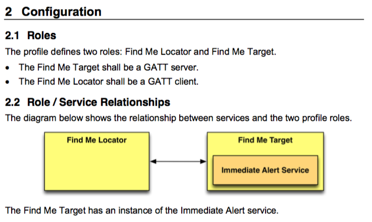
At Electronica last fall my project included two strips of WS2812B LEDs.  These LEDs were controlled by a PSoC 4 UDB component that my friend Mark Hastings built.  Here is a link to his project called FunWithLEDs.  That was cool and everything but I wanted to drive the LEDs from my PSoC 6.  The problem that I have is that there are no UDBs in the PSoC 6-2M and I’m not really a bit-banging kind of guy… so this gave me a chance to use the PSoC 6 DMA.

In this article I will

  1. Show you how the WS2812B LEDs work
  2. Give you a schematic for a PSoC 6 to drive them
  3. Explain how to create and use a frame buffer for the LEDs
  4. Explain the PSoC 6 DMA
  5. Glue it all together in a project
  6. Take you through debugging the code (I made several bugs)
  7. Show you how to calculate and measure the performance
  8. Take you through another layer of debugging
  9. Explain DMA chaining
  10. Automatically send the frameBuffer
  11. Explain why I’m lucky it works

WS2812B

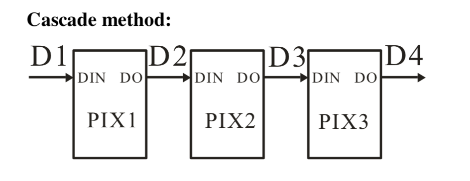
The WS2812B LED strips are an almost arbitrary length (not quite true – more on this later) string of pixels that can be cascaded together via a serial line like this:

If you look on the internet you can purchase these strings in a whole bunch of different configurations e.g. Mouser and Adafruit NeoPixel.

Each pixel actually has three individual LEDs – Red, Green and Blue.  And each LED is attached to an 8-bit PWM, giving you 256 values of intensity – which is also known as 24-bit color because of 3 LEDs times 8-bit color.  Sometimes this is also known as 16 Million Colors.  To set the color of an individual pixel you it send three bytes, one each for Red, Green and Blue.  When the LED receives the reset code it takes the most recent RGB values and turns it on.

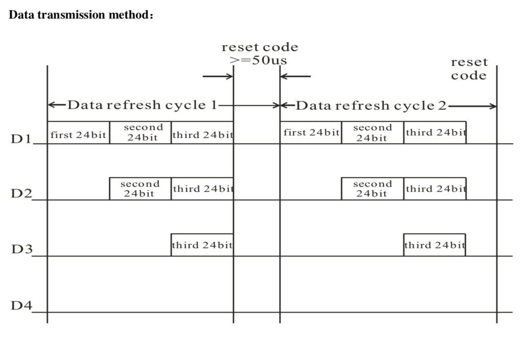
The communication protocol is cool.  When communication starts, a pixel takes its Red, Green and Blue value from the data stream, then passes on the rest of the bytes to the next pixels.  Basically each pixel peels off three bytes, then passes the rest through.  This scheme allows you to have almost any length string of pixels.  In the picture below you can see that the first pixels sees 3×3 bytes.  The second sees 2×3 bytes and the final pixel only sees its three bytes.

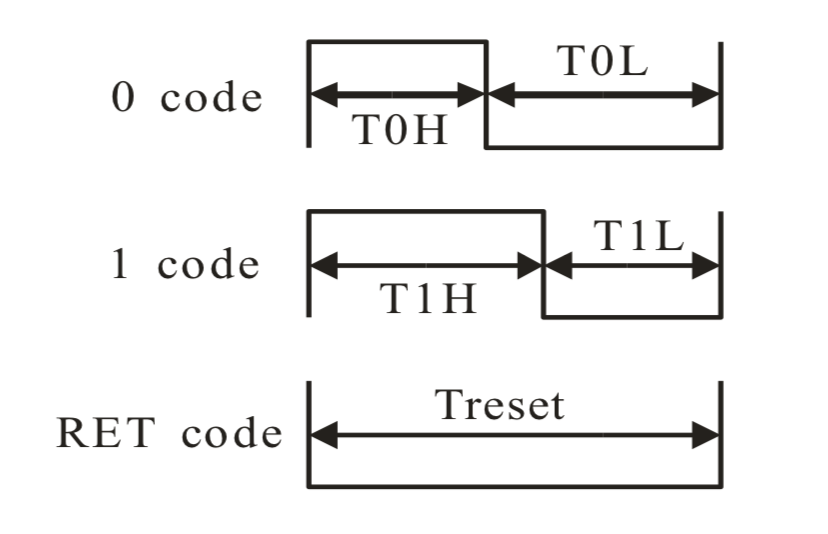
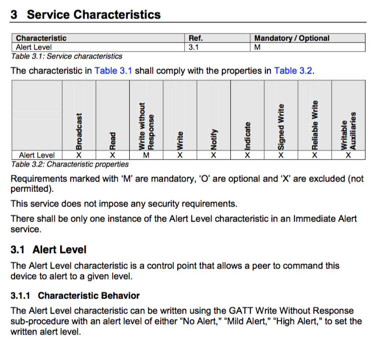
The only thing that is a bit weird in this protocol is that a “bit 1” is actually encoded as a long pulse of 1 followed by a short pulse of 0.  And a “bit 0” is short pulse of 1 followed by a long pulse of 0.  Here is a picture from the datasheet:

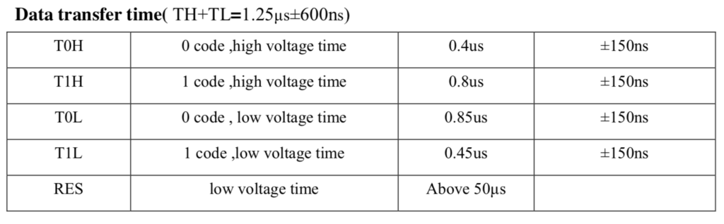
There is tons of blab-blabbing on the internet about how hard the timing is to deal with inside of the driver chip.  Here is the exact requirement:

My guess is that most of the heart ache is a result of people trying to bit-bang the protocol, which causes them to have to create fairly accurate, short timing loops.

But that isn’t what I am going to do.  But, Alan, what are you going to do?  First, observe from the table above that a T1H is double a T0H and a T0L is almost exactly double a T0H.  That means that the fundamental unit of time in this system is 0.4uS.  Which made me think to use the PSoC 6 to drive 0’s and 1’s out to the DI line of the first pixel at a rate of 1/0.4uS = 2.5 MHz using the SPI port.  This will let me encode 1 as 110 and encode 0 as 100.

Schematic

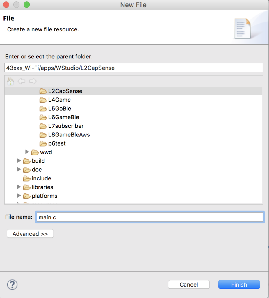
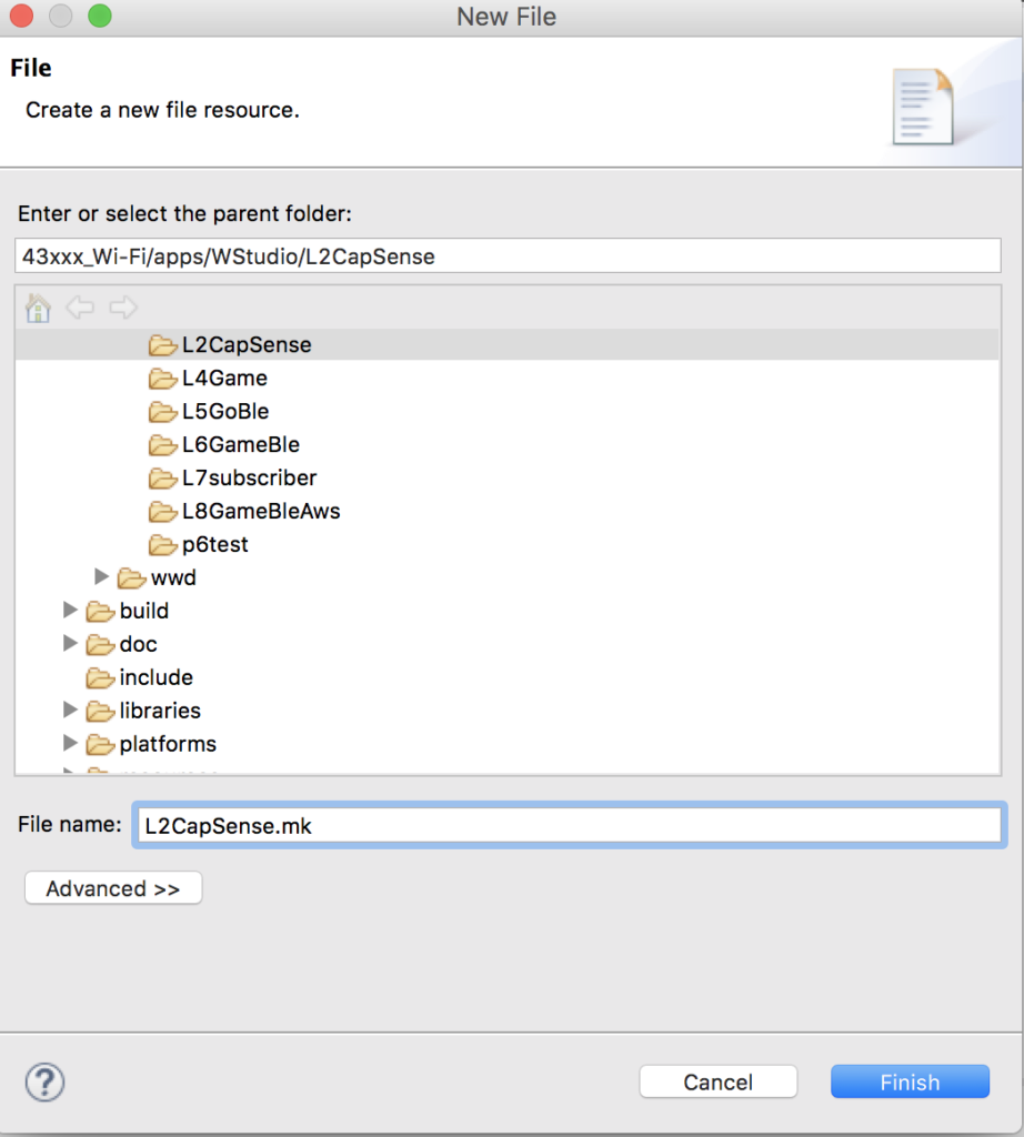
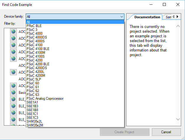
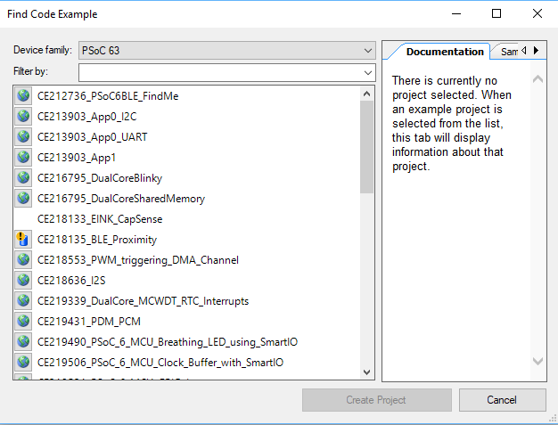
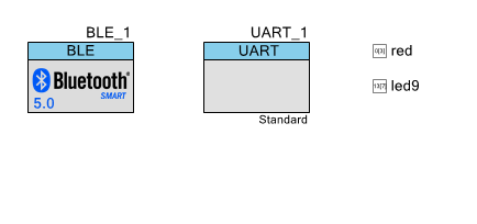
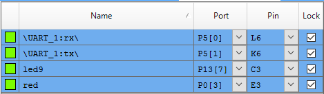
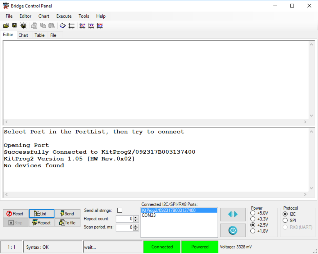
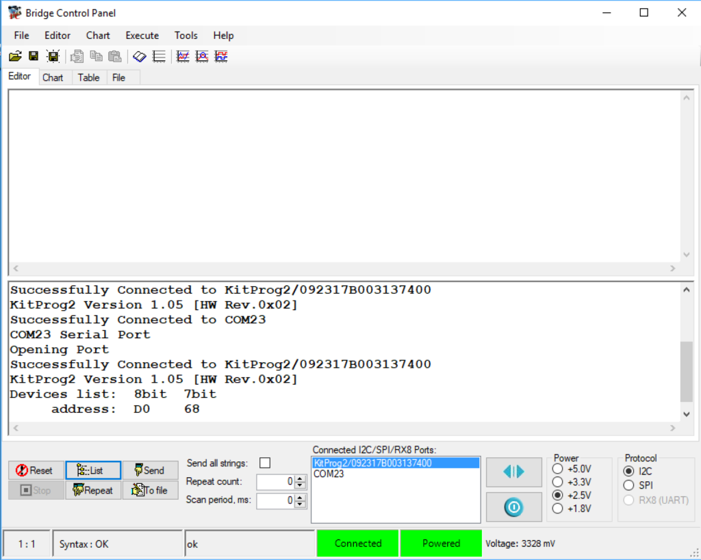
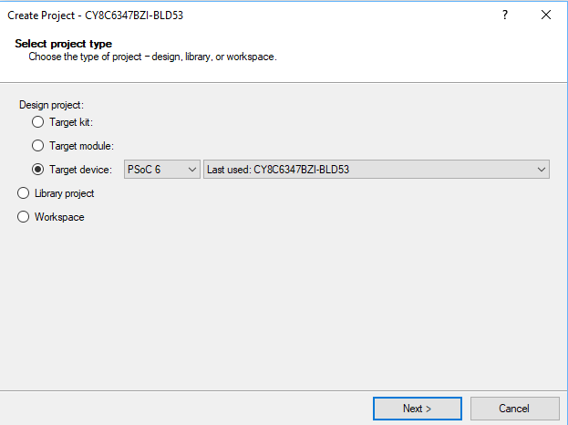
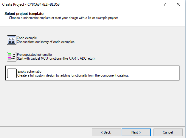
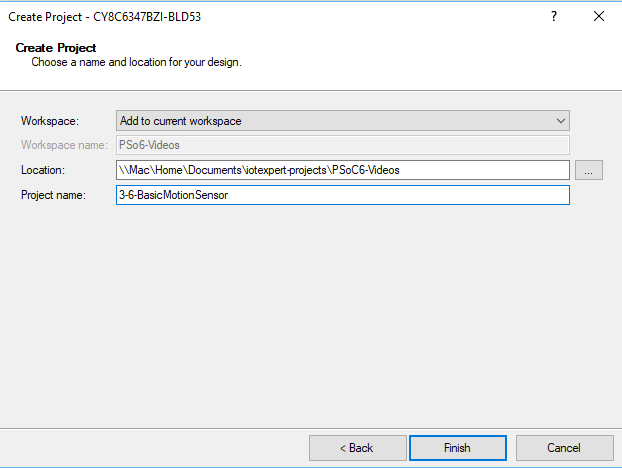
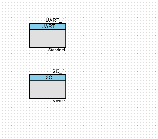
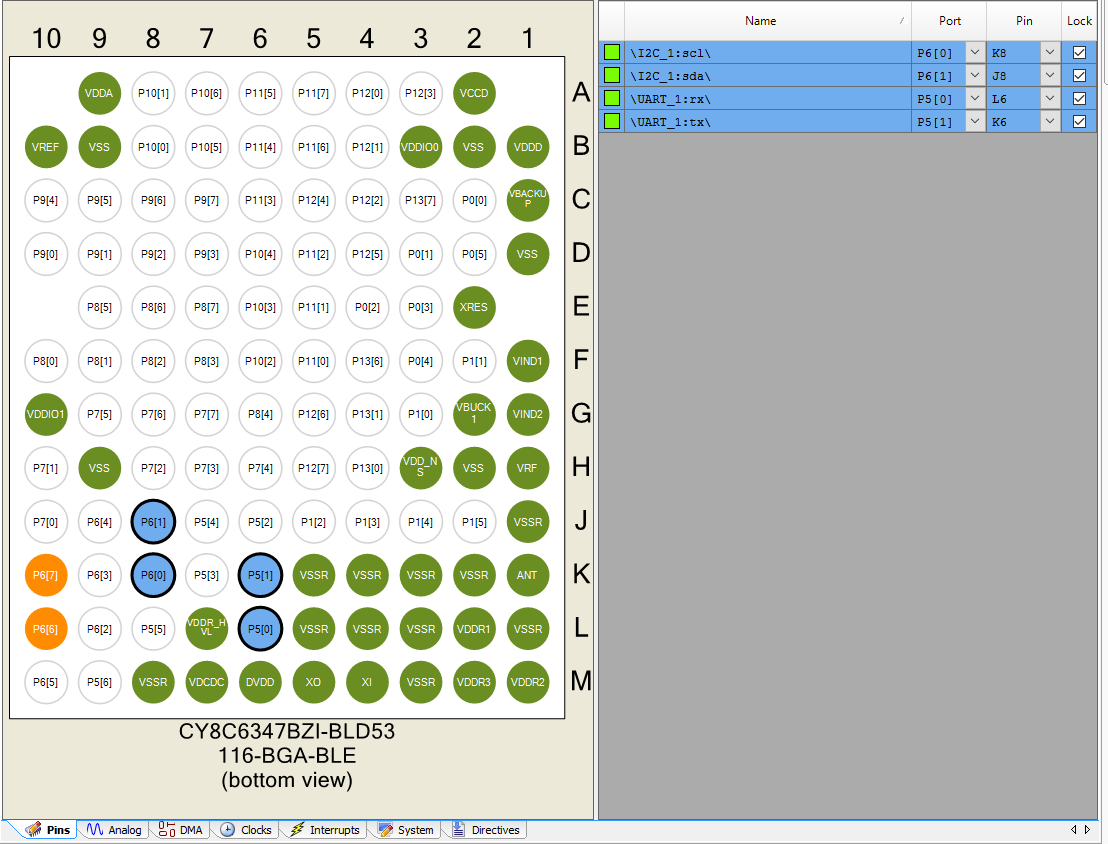
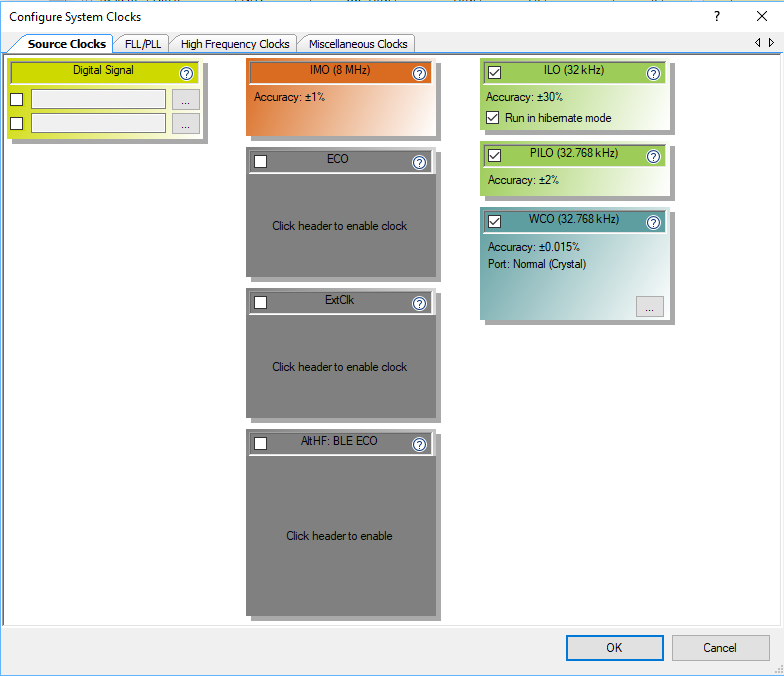
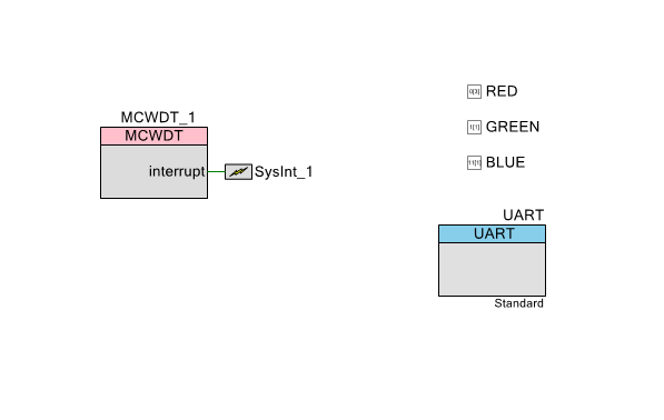
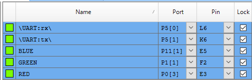
To build this project I started by making a new PSoC Creator Project.  I chose PSoC Creator instead of Modus Toolbox because I wanted to be able to use PSoC 4 component as well as PSoC 6.  My schematic has a SPI connected to DMA.  The DMA is connected to an interrupt.  A digital pin called “Red” which is attached to P0[3] on the board.  And finally a UART connected to the KitProg bridge.

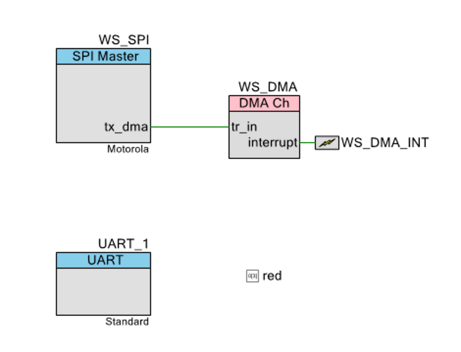
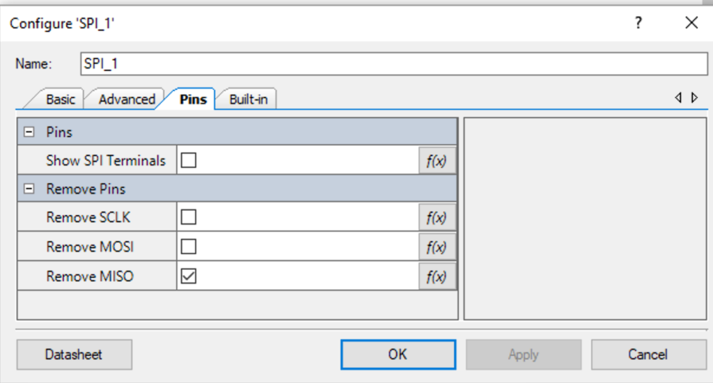
In the SPI Configuration I remove the MISO pin (because we dont need SPI input data).  I could also remove the SCLK pin, but I left it attached so that I could see what was happening with an oscilloscope (which I needed when I was trying to figure out the bugs)

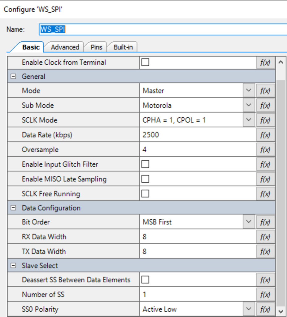
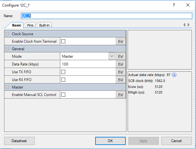
The Basic SPI is configured with a data rate of 2500kbs which is also known as 0.4uS per bit, as well as an oversample rate of 4.  The state machine of the SPI needs an input clock which is at least 2x the data rate.  If the MISO was still attached it might need an even higher input clock rate in order to oversample the input.  Notice that I also have one slave select line, which I was using to trigger the oscilloscope.  In the real system, there is no slave to select so you can use a 0 there.


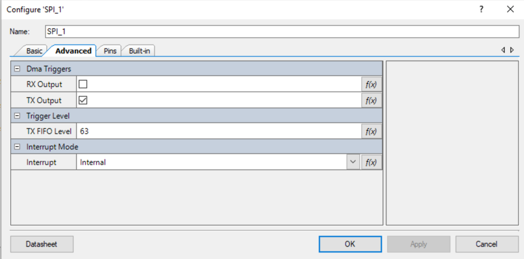
On the Advanced table I enable “Dma Trigger on Tx Output” with the Fifo set to “63”.  This will cause the DMA trigger to be asserted anytime the transmit FIFO falls below 63 bytes.

WS2812 Framebuffer Code

From the schematic above you can see that my plan is to DMA data out of a buffer into the SPI transmit FIFO.  Given that you need a 1 to be 110 and a 0 to be 100 this will require 3 output bytes for each RGV value.  And each pixel will take 3-bits per bit or 3*3*8 bits or 9 bytes total per pixel.

As an Application developer using the WS2812 library, it will be nice to have functions that let you think in 3-bytes (RGB) and the library will translate those values into the 9-bytes required by the SPI.  OK, lets build the library with that in mind.  First I make some defines to get rid of the magic numbers.  Then I make the frame buffer which will hold the 9-byte formatted information.  Notice that I have a define called “WS_OFFSET” which I will talk about in more detail later.

#define WS_ZOFFSET (1)
#define WS_ONE3  (0b110<<24)
#define WS_ZERO3 (0b100<<24)
#define WS_NUM_LEDS (5)
#define WS_SPI_BIT_PER_BIT (3)
#define WS_COLOR_PER_PIXEL (3)
#define WS_BYTES_PER_PIXEL (WS_SPI_BIT_PER_BIT * WS_COLOR_PER_PIXEL)

static uint8_t WS_frameBuffer[WS_NUM_LEDS*WS_BYTES_PER_PIXEL+WS_ZOFFSET];

The next thing I create is a function to turn a 1-byte input into the 3-byte output.  It takes 1 bit at a time and then or’s in either 110 or 100.  It returns a uint32_t … but with the first byte is set to 0x0.

// Function: convert3Code
// This function takes an 8-bit value representing a color
// and turns it into a WS2812 bit code... where 1=110 and 0=011
// 1 input byte turns into three output bytes of a uint32_t
uint32_t WS_convert3Code(uint8_t input)
{
    uint32_t rval=0;
    for(int i=0;i<8;i++)
    {
        if(input%2)
        {
            rval |= WS_ONE3;
        }
        else
        {
            rval |= WS_ZERO3;
        }
        rval = rval >> 3;
        
        input = input >> 1;
    }
    return rval;
}

This first helper function WS_setRGB  will configure a specific pixel in the frameBuffer to be the RGB value encoded as 9-bytes.  Notice that the order in the frameBuffer is Green, Red, Blue (not RGB order)

// Function: WS_setRGB
// Takes a position and a three byte rgb value and updates the WS_frameBuffer with the correct 9-bytes
void WS_setRGB(int led,uint8_t red, uint8_t green, uint8_t blue)
{
    
    typedef union {
    uint8_t bytes[4];
    uint32_t word;
    } WS_colorUnion;
    
    WS_colorUnion color;
    color.word = WS_convert3Code(green);
    WS_frameBuffer[led*WS_BYTES_PER_PIXEL+WS_ZOFFSET] = color.bytes[2];
    WS_frameBuffer[led*WS_BYTES_PER_PIXEL+1+WS_ZOFFSET] = color.bytes[1];
    WS_frameBuffer[led*WS_BYTES_PER_PIXEL+2+WS_ZOFFSET] = color.bytes[0];
    
    color.word = WS_convert3Code(red);
    WS_frameBuffer[led*WS_BYTES_PER_PIXEL+3+WS_ZOFFSET] = color.bytes[2];
    WS_frameBuffer[led*WS_BYTES_PER_PIXEL+4+WS_ZOFFSET] = color.bytes[1];
    WS_frameBuffer[led*WS_BYTES_PER_PIXEL+5+WS_ZOFFSET] = color.bytes[0];

    color.word = WS_convert3Code(blue);
    WS_frameBuffer[led*WS_BYTES_PER_PIXEL+6+WS_ZOFFSET] = color.bytes[2];
    WS_frameBuffer[led*WS_BYTES_PER_PIXEL+7+WS_ZOFFSET] = color.bytes[1];
    WS_frameBuffer[led*WS_BYTES_PER_PIXEL+8+WS_ZOFFSET] = color.bytes[0];
}

DMA Code & Configuration

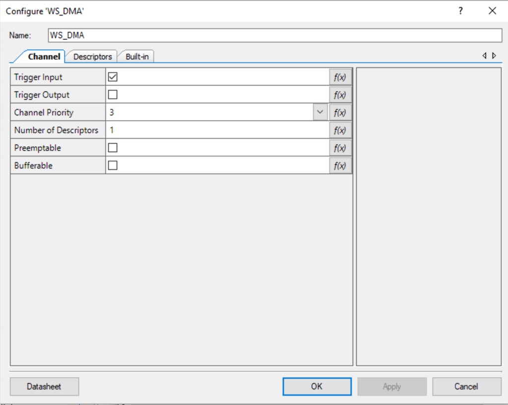
The DMA configuration starts with the defaults.  The channel priority doesn’t matter as I am only using one channel in this design.  I left the default descriptors set to 1 … which actually turns out to be a problem later on in my debugging (more on this later)

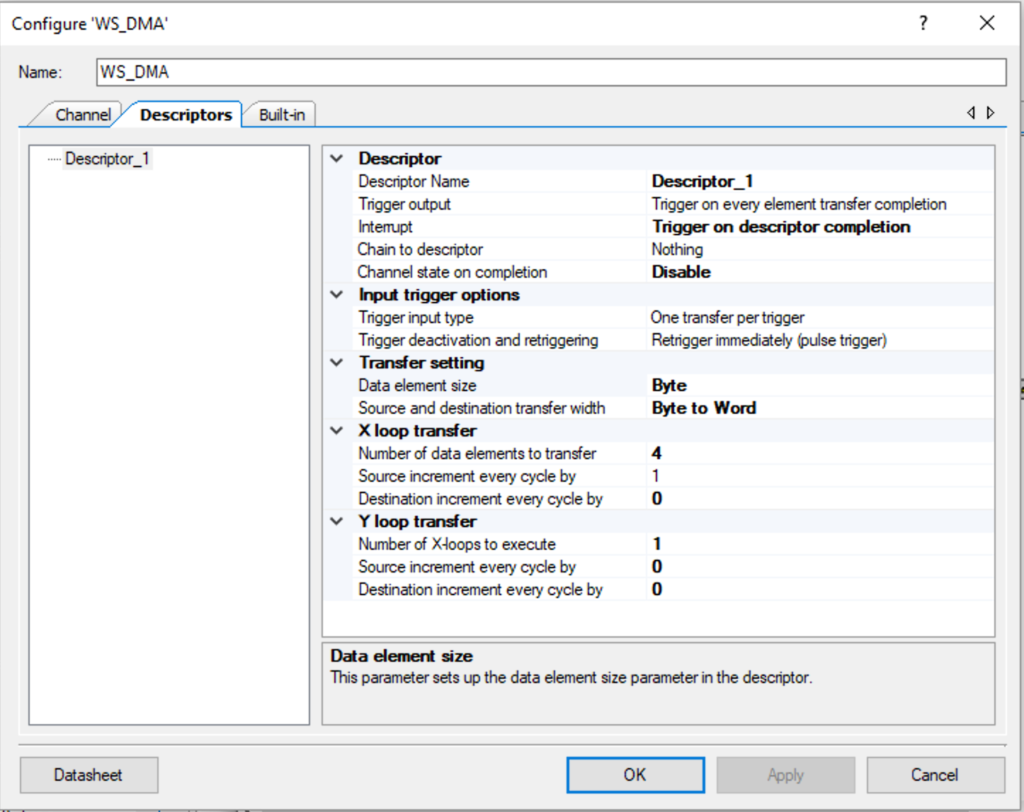
The descriptor is configured like this.  The configuration includes:

  1. The trigger output is unused
  2. An interrupt at the end (which I dont use)
  3. No chaining (meaning only on descriptor)
  4. The channel is disabled at the end (which I reset in software)
  5. One transfer per trigger (1-byte –> 1 word)
  6. As long as the trigger is active keep triggering (retrigger immediately)
  7. My buffer has bytes… but the input to the FIFO is words so setup Byte–>Word
  8. Hardcoded to 4-bytes of transfer, but I change this with the firmware based on the size of the frameBuffer

The first bit of code is an interrupt service routine which is attached to the DMA chain.  When I was trying to debug this originally I used the ISR to toggle an LED when the DMA was complete.  Now it doesnt do anything, but I left it in case I want to add something later.

// This is the interrupt handler for the WS DMA
// It doesnt do anything... and is just a stub
static void WS_DMAComplete(void)
{
    Cy_DMA_Channel_ClearInterrupt(WS_DMA_HW, WS_DMA_DW_CHANNEL);   
}

The function WS_DMAConfigure is used to:

  1. Initializes the DMA Descriptor
  2. Initializes the interrupt (which doenst do anything)
  3. Enables the DMA block
static void WS_DMAConfigure(void)
{
    /* Initialize descriptor */
    Cy_DMA_Descriptor_Init(&WS_DMA_Descriptor_1, &WS_DMA_Descriptor_1_config);
     
    /* Set source and destination for descriptor 1 */
    Cy_DMA_Descriptor_SetSrcAddress(&WS_DMA_Descriptor_1, (uint8_t *)WS_frameBuffer);
    Cy_DMA_Descriptor_SetDstAddress(&WS_DMA_Descriptor_1, (void *)&WS_SPI_HW->TX_FIFO_WR);
    Cy_DMA_Descriptor_SetXloopDataCount(&WS_DMA_Descriptor_1,sizeof(WS_frameBuffer));
    
     /* Initialize and enable the interrupt from WS_DMA */
    Cy_SysInt_Init(&WS_DMA_INT_cfg, &WS_DMAComplete);
    NVIC_EnableIRQ(WS_DMA_INT_cfg.intrSrc);
    Cy_DMA_Channel_SetInterruptMask(WS_DMA_HW, WS_DMA_DW_CHANNEL, WS_DMA_INTR_MASK);
    
    Cy_DMA_Enable(WS_DMA_HW);    
}

To actually make the DMA “go”, the function WS_DMATrigger sets up the DMA Channel, and then enables it.

void WS_DMATrigger()
{
        /* Initialize the DMA channel */
    cy_stc_dma_channel_config_t channelConfig;	
    channelConfig.descriptor  = &WS_DMA_Descriptor_1;
    channelConfig.preemptable = WS_DMA_PREEMPTABLE;
    channelConfig.priority    = WS_DMA_PRIORITY;
    channelConfig.enable      = false;
    Cy_DMA_Channel_Init(WS_DMA_HW, WS_DMA_DW_CHANNEL, &channelConfig);
    Cy_DMA_Channel_Enable(WS_DMA_HW,WS_DMA_DW_CHANNEL);
}

Gluing it all together

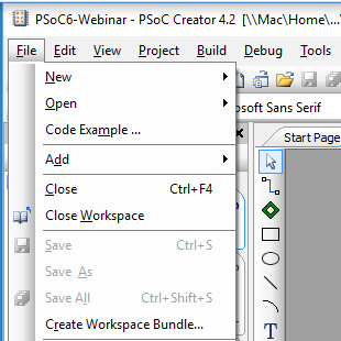
Now that we have a complete library, the last thing to do is build a command line interface to test it.   Lines 299-306 just get things going.  Then lines 308-310 turn on the systick timer and set it to a 1ms period.  I use the timer to trigger the DMA every 33ms.  The last part allows me to type a character and have it test a part of the system.

int main(void)
{
__enable_irq(); /* Enable global interrupts. */
UART_1_Start();
setvbuf( stdin, NULL, _IONBF, 0 ); 
printf("Started\n");   
WS_Start();
Cy_SysTick_Init(CY_SYSTICK_CLOCK_SOURCE_CLK_IMO,8000);
Cy_SysTick_Enable();
Cy_SysTick_SetCallback(0,WS_SysTickHandler);
for(;;)
{
char c=getchar();
switch(c)
{        
case 'u':
printf("Enable auto DMA updating\n");
Cy_SysTick_SetCallback(0,WS_SysTickHandler);
break;
case 'U':
printf("Disable auto DMA updating\n");
Cy_SysTick_SetCallback(0,0);
break;
case 't':
printf("Trigger DMA\n");
WS_DMATrigger();
break;        
case 'r':
WS_setRGB(0,0xFF,0,0);
printf("Set LED0 Red\n");
break;
case 'g':
WS_setRGB(0,0,0xFF,0);
printf("Set LED0 Green\n");
break;            
case 'O':
WS_setRange(0,WS_NUM_LEDS-1,0,0,0);
printf("Turn off all LEDs\n");
break;
case 'o':
WS_setRange(0,WS_NUM_LEDS-1,0xFF,0xFF,0xFF);
printf("Turn on all LEDs\n");
break;
case 'b':
WS_setRGB(0,0,0,0xFF);
printf("Set LED0 Blue\n");
break;        
case 'R':
WS_setRange(0,WS_NUM_LEDS-1,0x80,0,0);
printf("Turn on all LEDs RED\n");
break;
case 'G':
WS_setRange(0,WS_NUM_LEDS-1,0,0x80,0);
printf("Turn on all LEDs Green\n");
break;
case 'B':
WS_setRange(0,WS_NUM_LEDS-1,0,0,0x80);
printf("Turn on all LEDs Blue\n");
break;     
case 'a':
WS_initMixColorRGB();
printf("Turn on all LEDs RGB Pattern\n");
break;
case '?':
printf("u\tEnable Auto Update of LEDs\n");
printf("U\tDisable Auto Update of LEDs\n");
printf("t\tTrigger the DMA\n");
printf("r\tSet the first pixel Red\n");
printf("g\tSet the first pixel Green\n");
printf("b\tSet the first pixel Blue\n");
printf("O\tTurn off all of the pixels\n");
printf("o\tSet the pixels to white full on\n");
printf("R\tSet all of the pixels to Red\n");
printf("G\tSet all of the pixels to Green\n");
printf("B\tSet all of the pixels to Blue\n");
printf("a\tSet pixels to repeating RGBRGB\n");
printf("?\tHelp\n");
break;
}
}
}

Why is it not working?

After all of that I programmed the PSoC…. and… I got nothing.  This made me very unhappy because I wondered what the cause was.  Specifically, I was worried that I didn’t understand how to talk to the WS2812Bs.

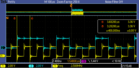
My first step in debugging the problem was to get out the oscilloscope.  When I captured the data here is what I got.  The blue trace is the MOSI line which is driving the LED string, and the yellow trace is the SPI clock.  You can see from the measurement that the clock pulses are 392ns = 0.39uS … thats good.  You can see in the picture that the first “pulse” on the blue line  is 2 clocks long, thats good, but it is immediately followed by a 2 clock long 0.  That isn’t good.

Hang on I need 110 for 1 and 100 for 0… but I got 110 then 011.  No good.  Here is the code with the bug

#define ONE3  (0b110<<24)
#define ZERO3 (0b011<<24)

Once I fix that to be

#define ONE3  (0b110<<24)
#define ZERO3 (0b100<<24)

Things look good now.

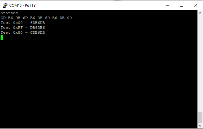
However, this bug is really stupid because I did a partial job putting in unit test.  Here is the stupid part.  I wrote this:

    setRGB(0,0,0x80,0);
for(int i=0;i<10;i++)
{
printf("%02X ",frameBuffer[i]);
}
printf("\n");
printf("Test 0x00 = %0X\n",convert3Code(0));
printf("Test 0xFF = %0X\n",convert3Code(0xFF));
printf("Test 0x80 = %0X\n",convert3Code(0x80));

Which yielded

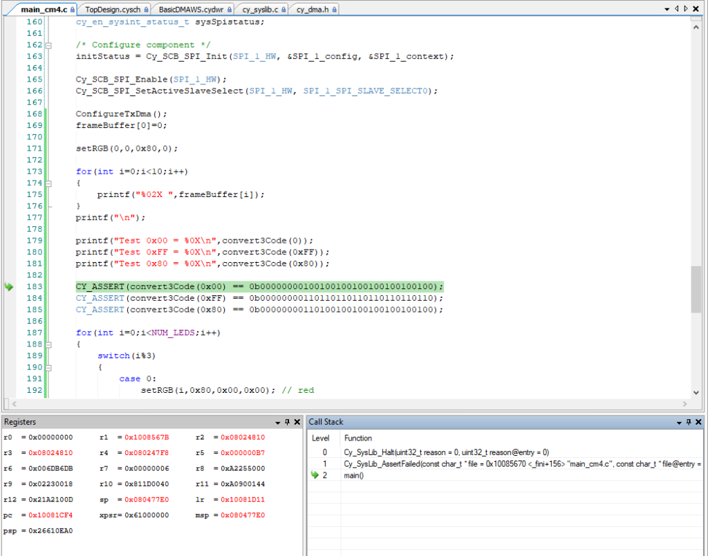
What would have been much better would have been to do this:

    setRGB(0,0,0x80,0);
for(int i=0;i<10;i++)
{
printf("%02X ",frameBuffer[i]);
}
printf("\n");
printf("Test 0x00 = %0X\n",convert3Code(0));
printf("Test 0xFF = %0X\n",convert3Code(0xFF));
printf("Test 0x80 = %0X\n",convert3Code(0x80));
CY_ASSERT(convert3Code(0x00) == 0b00000000100100100100100100100100);
CY_ASSERT(convert3Code(0xFF) == 0b00000000110110110110110110110110);
CY_ASSERT(convert3Code(0x80) == 0b00000000110100100100100100100100);

Which would have put me here when the assert failed:

How long does it take to run?

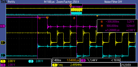
The next thing that I was curious about is how long does it take to dump one frameBuffer into the LED string.  Well, the simplest thing seems to be to setup a longer transaction (25 LEDs) and then measure.  In the screen shot below you can see that is 721 uS for 25 LEDs or about 29uS per LED.

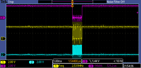
Which I suppose makes sense as 1 LED is 9 bytes or 9*8=72 bits at 0.4uS per but = 28.8uS.  This means 1000 LEDs is about 29 milliseconds.  Which means that you can easily do 1000 LEDs at 30Hz.
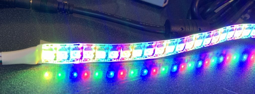
Why is it “yellow”?

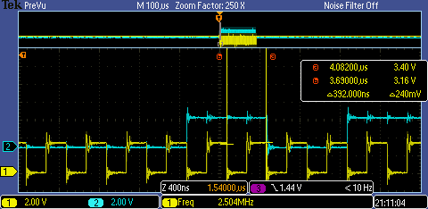
As I was testing the runtime I noticed that the first LED of the chain was always yellow.  Why is that? (Notice that the LEDs are too bright to take a picture of and you can really only see the yellow in the reflection)

When I looked at the oscilloscope trace I notice that the pulse width of the first “1” was 1.2uS (the blue line is the data).  This is a result of the Serial Communication Block SPI pulling up the MOSI line a good while before it enables the chip select (the purple trace) which has the effect of making a very long 1 to start with.  This obviously is not a problem for the SPI protocol as it is clocked by the serial clock line.  But in this case where the LEDs are self-clocked it makes for a long 1.

OK, how do I fix that?  The cheap way to fix this is to make the first bit of the sequence a 0.  But, that would be a major pain because that would effectively shift every bit in the frame buffer over by 1-bit which is a pain in the ass.  So, to fix it I just make the entire first byte of the buffer be 0 which means it takes an extra byte and 8×0.4 uS = 3.2uS longer.  No big deal.

The code change is to add 1 byte to the buffer (which I called the WS_ZOFFSET)

#define WS_ZOFFSET (1)
#define WS_ONE3  (0b110<<24)
#define WS_ZERO3 (0b100<<24)
#define WS_NUM_LEDS (5)
#define WS_SPI_BIT_PER_BIT (3)
#define WS_COLOR_PER_PIXEL (3)
#define WS_BYTES_PER_PIXEL (WS_SPI_BIT_PER_BIT * WS_COLOR_PER_PIXEL)
static uint8_t WS_frameBuffer[WS_NUM_LEDS*WS_BYTES_PER_PIXEL+WS_ZOFFSET];

Then offset all of the writes by WS_ZOFFSET

// Function: WS_setRGB
// Takes a position and a three byte rgb value and updates the WS_frameBuffer with the correct 9-bytes
void WS_setRGB(int led,uint8_t red, uint8_t green, uint8_t blue)
{
typedef union {
uint8_t bytes[4];
uint32_t word;
} WS_colorUnion;
WS_colorUnion color;
color.word = WS_convert3Code(green);
WS_frameBuffer[led*WS_BYTES_PER_PIXEL+WS_ZOFFSET] = color.bytes[2];
WS_frameBuffer[led*WS_BYTES_PER_PIXEL+1+WS_ZOFFSET] = color.bytes[1];
WS_frameBuffer[led*WS_BYTES_PER_PIXEL+2+WS_ZOFFSET] = color.bytes[0];
color.word = WS_convert3Code(red);
WS_frameBuffer[led*WS_BYTES_PER_PIXEL+3+WS_ZOFFSET] = color.bytes[2];
WS_frameBuffer[led*WS_BYTES_PER_PIXEL+4+WS_ZOFFSET] = color.bytes[1];
WS_frameBuffer[led*WS_BYTES_PER_PIXEL+5+WS_ZOFFSET] = color.bytes[0];
color.word = WS_convert3Code(blue);
WS_frameBuffer[led*WS_BYTES_PER_PIXEL+6+WS_ZOFFSET] = color.bytes[2];
WS_frameBuffer[led*WS_BYTES_PER_PIXEL+7+WS_ZOFFSET] = color.bytes[1];
WS_frameBuffer[led*WS_BYTES_PER_PIXEL+8+WS_ZOFFSET] = color.bytes[0];
}

Why did it crash?

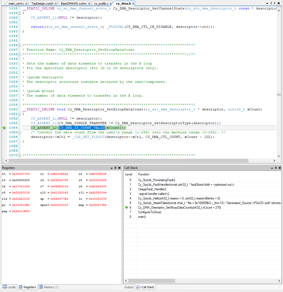
While I was testing the runtime of the DMA loop, I kept increasing the number of LEDs.  When I typed 30, the PSoC crashed and was no longer responsive.  When this happens it is always useful to click on “Debug->Attach to Running Target”.  When I did that I ended up with this screen.  This tells me that there was an assert that was triggered.  When I hovered over the CY_DMA_IS_COUNT_VALID I realized that you can only DMA 256 bytes per descriptor… and with 30 LEDs I need 270 bytes… which means that I need to chain descriptors.

Chaining DMA Descriptors

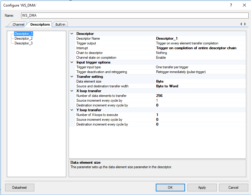
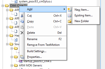
You are allowed to create multiple DMA descriptors in the component configuration like this:

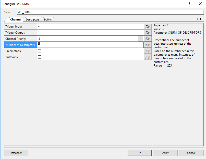
Which will give you three descriptors to configure.

And when you build the code you will find configuration structures for each of the descriptors in the generated source.  Here is a clip of code from then WS_DMA.C (which PSoC Creator generates)

const cy_stc_dma_descriptor_config_t WS_DMA_Descriptor_2_config =
{
.retrigger       = CY_DMA_RETRIG_IM,
.interruptType   = CY_DMA_1ELEMENT,
.triggerOutType  = CY_DMA_1ELEMENT,
.channelState    = CY_DMA_CHANNEL_ENABLED,
.triggerInType   = CY_DMA_1ELEMENT,
.dataSize        = CY_DMA_WORD,
.srcTransferSize = CY_DMA_TRANSFER_SIZE_DATA,
.dstTransferSize = CY_DMA_TRANSFER_SIZE_DATA,
.descriptorType  = CY_DMA_SINGLE_TRANSFER,
.srcAddress      = NULL,
.dstAddress      = NULL,
.srcXincrement   = 1L,
.dstXincrement   = 1L,
.xCount          = 1UL,
.srcYincrement   = 1L,
.dstYincrement   = 1L,
.yCount          = 1UL,
.nextDescriptor  = NULL
};
cy_stc_dma_descriptor_t WS_DMA_Descriptor_2 =
{
.ctl = 0UL,
.src = 0UL,
.dst = 0UL,
.xCtl = 0UL,
.yCtl = 0UL,
.nextPtr = 0UL
};

The problem is that it will be much better for the user of the WS2812 library to be able to configure the number of LEDs have it adjust the DMA chain automatically.  So, to chain the DMA Descriptors together I created my own descriptor initialization code:

  1. Calculate the number of descriptors required by looking at the sizeof the WS_frameBuffer.  You need to have at least 1.
  2. Create an array with enough descriptors
  3. Copy one of the descriptor initialization structures into my code (from the generated source), so that I can use the Cy_DMA_Descriptor_Init function
  4. Loop through all of the descriptors and initialize them.  Notice that I make the next descriptor be the next descriptor in the array
  5. The last descriptor will have less bytes, no next descriptor and you want to disable the channel when it is done
#define WS_NUM_DESCRIPTORS (sizeof(WS_frameBuffer) / 256 + 1)
static cy_stc_dma_descriptor_t WSDescriptors[WS_NUM_DESCRIPTORS];
static void WS_DMAConfigure(void)
{
// I copies this structure from the PSoC Creator Component configuration 
// in generated source
const cy_stc_dma_descriptor_config_t WS_DMA_Descriptors_config =
{
.retrigger       = CY_DMA_RETRIG_IM,
.interruptType   = CY_DMA_DESCR_CHAIN,
.triggerOutType  = CY_DMA_1ELEMENT,
.channelState    = CY_DMA_CHANNEL_ENABLED,
.triggerInType   = CY_DMA_1ELEMENT,
.dataSize        = CY_DMA_BYTE,
.srcTransferSize = CY_DMA_TRANSFER_SIZE_DATA,
.dstTransferSize = CY_DMA_TRANSFER_SIZE_WORD,
.descriptorType  = CY_DMA_1D_TRANSFER,
.srcAddress      = NULL,
.dstAddress      = NULL,
.srcXincrement   = 1L,
.dstXincrement   = 0L,
.xCount          = 256UL,
.srcYincrement   = 0L,
.dstYincrement   = 0L,
.yCount          = 1UL,
.nextDescriptor  = 0
};
for(unsigned int i=0;i<WS_NUM_DESCRIPTORS;i++)
{
Cy_DMA_Descriptor_Init(&WSDescriptors[i], &WS_DMA_Descriptors_config);
Cy_DMA_Descriptor_SetSrcAddress(&WSDescriptors[i], (uint8_t *)&WS_frameBuffer[i*256]);
Cy_DMA_Descriptor_SetDstAddress(&WSDescriptors[i], (void *)&WS_SPI_HW->TX_FIFO_WR);
Cy_DMA_Descriptor_SetXloopDataCount(&WSDescriptors[i],256); // the last
Cy_DMA_Descriptor_SetNextDescriptor(&WSDescriptors[i],&WSDescriptors[i+1]);
}
// The last one needs a bit of change
Cy_DMA_Descriptor_SetXloopDataCount(&WSDescriptors[WS_NUM_DESCRIPTORS-1],sizeof(WS_frameBuffer)-256*(WS_NUM_DESCRIPTORS-1)); // the last
Cy_DMA_Descriptor_SetNextDescriptor(&WSDescriptors[WS_NUM_DESCRIPTORS-1],0);
Cy_DMA_Descriptor_SetChannelState(&WSDescriptors[WS_NUM_DESCRIPTORS-1],CY_DMA_CHANNEL_DISABLED);
/* Initialize and enable the interrupt from WS_DMA */
Cy_SysInt_Init(&WS_DMA_INT_cfg, &WS_DMAComplete);
NVIC_EnableIRQ(WS_DMA_INT_cfg.intrSrc);
Cy_DMA_Channel_SetInterruptMask(WS_DMA_HW, WS_DMA_DW_CHANNEL, WS_DMA_INTR_MASK);
Cy_DMA_Enable(WS_DMA_HW);    
}

With all of that done, the last change is to change the DMA channel initialization code to use the correct first descriptor

void WS_DMATrigger()
{
cy_stc_dma_channel_config_t channelConfig;	
channelConfig.descriptor  = &WSDescriptors[0];
channelConfig.preemptable = WS_DMA_PREEMPTABLE;
channelConfig.priority    = WS_DMA_PRIORITY;
channelConfig.enable      = false;
Cy_DMA_Channel_Init(WS_DMA_HW, WS_DMA_DW_CHANNEL, &channelConfig);
Cy_DMA_Channel_Enable(WS_DMA_HW,WS_DMA_DW_CHANNEL);
}

Automatically send the Frame Buffer

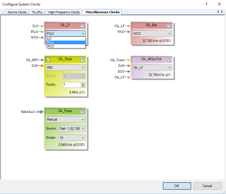
I initially “triggered” the DMA using keyboard commands that called the function WS_DMATrigger.  But after I got things working I realized that what I really wanted to do was update the “screen” aka the strip of LEDs at about 30Hz.  To do this I turn on the ARM SysTick timer to call my function WS_SysTickHandler every 1ms.

    Cy_SysTick_Init(CY_SYSTICK_CLOCK_SOURCE_CLK_IMO,8000);
Cy_SysTick_Enable();

In the WS_SysTickHandler, I count the number of times I have been called and store it in a static variable called “count”.  When count gets to 33 (or greater) meaning that 33mS has gone by, I check to make sure that the DMA is disabled and then I call the update function.  I also reset the timer back to 0.

void WS_SysTickHandler()
{
static int count=0;
if((Cy_DMA_Channel_GetStatus(WS_DMA_HW,WS_DMA_DW_CHANNEL) & CY_DMA_INTR_CAUSE_COMPLETION) && count++>32)
{
WS_DMATrigger();
count = 0;
}
}

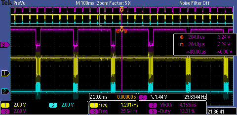
With that installed I get a nice 30Hz update.  The screenshot below is configured with 144 Pixels and it take 4.15mS to update the screen which is about a 12% duty cycle.

I’m Lucky it Works

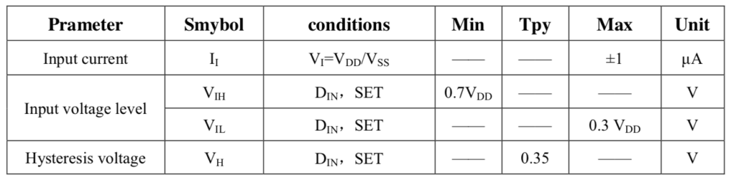
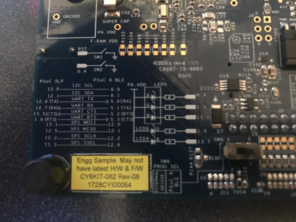
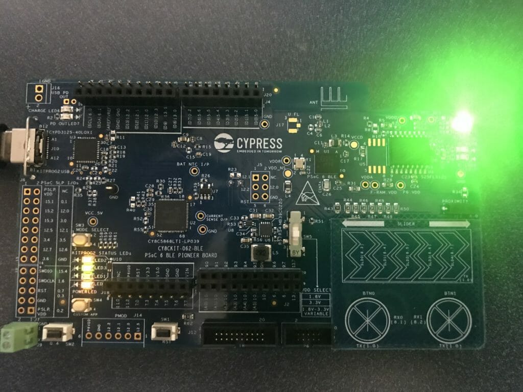
The last thing to observe in all of this is that I am driving the LED string with a 5V wall wart.

And according to the datasheet VIH is 0x7 * VDD = 3.5V … and I am driving it with a PSoC 6 with 3.3V.  Oh well.

All of this source code is available at GitHub or you can clone git@github.com:iotexpert/WS2812.git

Mouser PSoC 6-WiFi-BT L8: Integrate WiFi and AWS Into the Game

Designing low-power, cloud-connected IoT devices with PSoC® 6 MCU’s and WICED® Wi-Fi/Bluetooth

Summary

In this lesson we will move the subscriber app functionality into the main GameBle project (now called GameBleAws).  In order to do this, you need to turn the subscriber into a thread, and fix it so that messages that are sent to the PADDLE topic get turned into messages that can be sent to the paddleQueue.

To implement this lesson I will follow these steps:

  1. Create a New Project starting from L6GameBle
  2. Copy over subscriber.c and wifi_config_dct.h
  3. Update the Makefile
  4. Create subscriber.h
  5. Update main.c
  6. Update subscriber.c
  7. Test

Create a New Project

Copy and paste the L6GameBle project into a new project called L8GameBleAws using Copy/Paste

Create a new Make target for the GameBleAws project

Copy subscriber.c & wifi_config_dct.h

Use copy/paste to make a copy of the subscriber application and paste it into the GameBleAws project.  Once done your folder should look like this:

Update the Makefile

NAME := App_WStudio_L8GameBleAws
$(NAME)_SOURCES := main.c \
CapSenseThread.c \
GameThread.c \
cy_tft_display.c \
GoBleThread.c \
GoBle_db.c \
wiced_bt_cfg.c \
subscriber.c
$(NAME)_COMPONENTS := graphics/ugui \
libraries/drivers/bluetooth/low_energy \
protocols/AWS
WIFI_CONFIG_DCT_H := wifi_config_dct.h
$(NAME)_RESOURCES  := apps/aws/iot/rootca.cer \
apps/aws/iot/subscriber/client.cer \
apps/aws/iot/subscriber/privkey.cer
# To support Low memory platforms, disabling components which are not required
GLOBAL_DEFINES += WICED_CONFIG_DISABLE_SSL_SERVER \
WICED_CONFIG_DISABLE_DTLS \
WICED_CONFIG_DISABLE_ENTERPRISE_SECURITY \
WICED_CONFIG_DISABLE_DES \
WICED_CONFIG_DISABLE_ADVANCED_SECURITY_CURVES

Create subscriber.h

In order for the main.c to know about the awsThread (which is the former application_start of subscriber.c) you should create a file called subscriber.h.  Then you should define the awsThread function to match the wiced_thread_t function prototype (just a function that takes a wiced_thread_arg and returns void).

#pragma once
extern void awsThread( wiced_thread_arg_t arg );

Update main.c

To integrate the awsThread thread into your main project you need to add the “subscriber.h” to the includes:

#include "GameThread.h"
#include "GoBleThread.h"
#include "CapSenseThread.h"
#include "subscriber.h"
#include "wiced.h"

Add a new variable to hold the awsThreadHandle.

wiced_thread_t awsThreadHandle;

Finally you should launch the AWS thread by creating it with wiced_rtos_create_thread.

void application_start( )
{
wiced_init( );
wiced_rtos_init_queue(&paddleQueue,"paddleQueue",sizeof(game_msg_t),10);
wiced_rtos_create_thread(&blinkThreadHandle,7,"Blink Thread",pdlBlinkThread,500,0);
wiced_rtos_create_thread(&capsenseThreadHandle,7,"CapSense Thread",capSenseThread,1024,0);
wiced_rtos_create_thread(&gameThreadHandle,7,"game Thread",gameThread,4096,0);
GoBleThread_start();
wiced_rtos_create_thread(&awsThreadHandle,7,"AWS Thread",awsThread,4096,0);
}

Update subscriber.c

In order for subscriber.c to be useful you need to fix the includes, send the messages from the PADDLE topic to the game thread, and turn application_start into a thread.  Start by fixing the includes (just like we did in the BLE Example in Lesson 6)

#include "SystemGlobal.h"
#include "GameThread.h"

When you get a message to the PADDLE topic, you should parse it, then send a message to the game thread to move the paddle.  You do this exactly the same way as you did in the BLE project.  Notice that I protect the game thread by making sure it send a value less than 100.

        case WICED_AWS_EVENT_PAYLOAD_RECEIVED:
{
uint32_t val;
WPRINT_APP_INFO( ("[Application/AWS] Payload Received[ Topic: %.*s ]:\n", (int)data->message.topic_length, data->message.topic ) );
if(strncmp(WICED_TOPIC,(const char *)data->message.topic,strlen(WICED_TOPIC)) == 0 && data->message.data_length < 4)
{
sscanf((const char *)data->message.data,"%d",(int *)&val);
if(val>100)
val = 100;
WPRINT_APP_INFO(("Val = %d\n",(int)val));
game_msg_t msg;
msg.evt = MSG_POSITION;
msg.val = val;
wiced_rtos_push_to_queue(&paddleQueue,&msg,0);
}
}
break;

Test

I don’t really have a good program (like the GoBle) to test moving the paddle live.  But you can see that when the game is over, you can still move the paddle using AWS console.  In the screen shot below you can see that I moved the paddle to position 0.  And you can see that the BLE started at the same time as AWS.  Score.

Mouser PSoC 6-WiFi-BT L7 : Implement WiFi and AWS

Designing low-power, cloud-connected IoT devices with PSoC® 6 MCU’s and WICED® Wi-Fi/Bluetooth

Summary

In this lesson I am going to update one of the predefined application which we deliver as part of WICED Studio which knows how to connect to the AWS IoT Cloud to work on my network.  This will demonstrate WiFi and MQTT.  I will also fix the application so that it knows about a new MQTT Topic called “PADDLE” which will be used to send messages to move the game paddle.

To implement this project I will:

  1. Copy the subscriber from demo/aws/iot/pub_sub/subscriber
  2. Setup a “thing” on AWS and download the certificates
  3. Update the certificates in the WICED installation
  4. Update the project with my AWS configuration
  5. Test
  6. Update the project to be compatible with the Game
  7. Test

Copy Subscriber & Fix the Makefile

The first thing that I will do is copy/paste the subscriber application which can be found at demo/aws/iot/pub_sub/subscriber into my folder.  I will also rename the project to L7subscriber. Once that is done it should look like this:

Then you need to edit the Makefile to update the name of the project.

NAME := App_WStudio_L7subscriber

Go to Amazon.com and Create a “thing”

In order to connect to the AWS cloud you need to create a “thing”.  Go to the AWS console and click “Create”

We are just going to create one thing.  So, click “Create a single thing”

Give it a name, in this case Mouser.

AWS has device level security which is implemented with RSA certificates for each device.  So,  you need to let AWS create a certificate for you.

Once that is done download the device certificate and the two keys.  You need to 100% make sure you do this now, because you wont get another chance. I’m also going to activate the certificate once I have the certificate and keys.

Now attach a policy to your thing.  I already have the “ww101_policy” setup.

The policy looks like this.  Basically, things are wide open.

Update the Certificates

The last thing that you need is the most recent AWS certificate.  WICED expects that you use the RSA2048 bit key.

Now that you have the four security documents., you need to integrate them into your WICED installation.  To do this, change directories to ~/Documents/WICED-Studio-6.2/43xxx_Wi-Fi/resources/apps/aws/iot  Then copy the files, and then make symbolic links.  If you are not on a Mac or Linux then just copy the files and rename them appropriately.

Update the Project

AWS creates a virtual machine and runs an MQTT server on that machine.  You can find out the DNS name of that machine on the settings screen.  Here you can see my endpoint.  You will need to configure the WICED project to talk to your server.

You need to change the actual endpoint of your MQTT server in the AWS cloud on line 119

static wiced_aws_endpoint_info_t my_subscriber_aws_iot_endpoint = {
.transport           = WICED_AWS_TRANSPORT_MQTT_NATIVE,
.uri                 = "amk6m51qrxr2u-ats.iot.us-east-1.amazonaws.com",
.peer_common_name    = NULL,
.ip_addr             = {0},
.port                = WICED_AWS_IOT_DEFAULT_MQTT_PORT,
.root_ca_certificate = NULL,
.root_ca_length      = 0,
};

In the file wifi_config_dct.h you will need to change the CLIENT_AP_SSID and CLIENT_AP_PASSPHRASE for your network

/* This is the default AP the device will connect to (as a client)*/
#define CLIENT_AP_SSID       "WW101WPA"
#define CLIENT_AP_PASSPHRASE "yourpassword"
#define CLIENT_AP_BSS_TYPE   WICED_BSS_TYPE_INFRASTRUCTURE
#define CLIENT_AP_SECURITY   WICED_SECURITY_WPA2_MIXED_PSK
#define CLIENT_AP_CHANNEL    1
#define CLIENT_AP_BAND       WICED_802_11_BAND_2_4GHZ

Test

In order to test the project you will need to create a make target and program your development kit.

Once that is done you can go to the Amazon.com test console and send MQTT messages to the correct topic.

Here you can see the project attached to my network.  And successfully received the LIGHT ON message.

Update the Project for the Game

We know that the game doesn’t care about the LIGHT topic so, let’s change it to PADDLE.

#define WICED_TOPIC                                 "PADDLE"

And let’s assume that messages to the paddle topic are ASCII numbers <100.  So, we can parse the message and print it out.  Notice that I used sscanf to parse the message and we all know that is super dangerous.

        case WICED_AWS_EVENT_PAYLOAD_RECEIVED:
{
char buff[10];
uint32_t val;
WPRINT_APP_INFO( ("[Application/AWS] Payload Received[ Topic: %.*s ]:\n", (int)data->message.topic_length, data->message.topic ) );
if(strncmp(WICED_TOPIC,data->message.topic,strlen(WICED_TOPIC)) == 0 && data->message.data_length < 4)
{
sscanf(data->message.data,"%d",&val);
WPRINT_APP_INFO(("Val = %d\n",val));
}
}
break;

Test

After making those updates let’s program the whole shooting match again.  Then test by sending some messages to the PADDLE topic.

It’s good.  Things are working.

Mouser PSoC6-WiFi-BT L6 : Integrate GoBle Bluetooth into the Game

Designing low-power, cloud-connected IoT devices with PSoC® 6 MCU’s and WICED® Wi-Fi/Bluetooth

Summary

At this point we have a working BLE Remote Control and a working Game.  In this lesson I’ll merge the two projects together so that the GoBle remote control will be able to control the game paddle.  It will do this by creating messages (just like the CapSense messages) and sending them to the Game thread via the paddleQueue.  And it will send “Button0” messages when “Button A” is pressed.

To implement this lesson I will follow these steps:

  1. Copy everything into a new project
  2. Modify the Makefile
  3. Modify main.c
  4. Create a new make target
  5. Test it all to make sure things are still working
  6. Modify GoBleThread.c
  7. Program and Test

Copy L4Game into a new project L6GameBle

Use “copy” and “paste” to create a new project, when you paste give it the name “L6GameBle” (there is an error in the screenshot)

Copy the files GoBle_db.c/h, GoBleThread.c/h, and wiced_bt_cfg.c from the GoBle project into your new GameBle project.  After that is done your project should look like this:

Modify the Makefile

  1. Change the name of the App to “App_WStudio_L6GameBle”
  2. Add the new source files
  3. Add the BLE Library “libraries/drivers/bluetooth/low_energy”
NAME := App_WStudio_L6GameBle
$(NAME)_SOURCES := main.c \
CapSenseThread.c \
GameThread.c \
cy_tft_display.c \
GoBleThread.c \
GoBle_db.c \
wiced_bt_cfg.c
$(NAME)_COMPONENTS := graphics/ugui \
libraries/drivers/bluetooth/low_energy

Modify main.c

Add the include for the GeBleThread.

#include "GameThread.h"
#include "GoBleThread.h"
#include "CapSenseThread.h"
#include "wiced.h"

In the application_start function add a call GoBleThread_start() to get the GoBle thread going

void application_start( )
{
wiced_init( );
wiced_rtos_init_queue(&paddleQueue,"paddleQueue",sizeof(game_msg_t),10);
wiced_rtos_create_thread(&blinkThreadHandle,7,"Blink Thread",pdlBlinkThread,500,0);
wiced_rtos_create_thread(&capSenseThreadHandle,7,"CapSense Thread",capSenseThread,1024,0);
wiced_rtos_create_thread(&gameThreadHandle,7,"game Thread",gameThread,4096,0);
GoBleThread_start();
}

Create a new make target

Test it all to make sure things are still working

Run the make target and make sure that the game still plays and that you can get remote control messages.

Modify GoBleThread.c

Add the includes for the GameThread (to get access to the game message structure) and SystemGlobal (to get access to the queue)

#include "GameThread.h"
#include "SystemGlobal.h"

I don’t need (or want) the button/slider printout information.  So I will delete the old button code from goble_event_handler. (delete this stuff)

            WPRINT_APP_INFO(("# Buttons = %d ButtonMask=%02X Slider x=%02X Slider Y=%02X Raw=",(int)numButtons,(unsigned int)buttonMask,(unsigned int)sliderX,(unsigned int)sliderY));
for(int i=0;i<p_attr_req->data.write_req.val_len;i++)
{
WPRINT_APP_INFO(("%02X ",p_attr_req->data.write_req.p_val[i]));
}
WPRINT_APP_INFO(("\n"));

Now, update the code to send the slider and button information to the GameThread (via the paddleQueue).  You may have noticed that the slider on GoBle gives you 0->0xFF and the direction is the inverse from the game we setup.  So, I will scale the value to 100 and invert it so that the controller moves the paddle the right way on line 143.  The message format is exactly the same as what we setup for the CapSense.  This means the CapSense slider works at the same time as the GoBle controller.

   case GATT_ATTRIBUTE_REQUEST_EVT:
p_attr_req = &p_event_data->attribute_request;
if( p_attr_req->request_type == GATTS_REQ_TYPE_WRITE  && p_attr_req->data.handle == HDLC_GOBLE_SERIALPORTID_VALUE)
{
uint32_t numButtons = p_attr_req->data.write_req.p_val[3];
uint32_t sliderY = p_attr_req->data.write_req.p_val[5+numButtons];
uint32_t sliderX = p_attr_req->data.write_req.p_val[6+numButtons];
uint32_t buttonMask = 0x00;
for(int i=0;i<numButtons;i++)
{
buttonMask |= (1<<p_attr_req->data.write_req.p_val[5+i]);
}
game_msg_t msg;
msg.evt = MSG_POSITION;
msg.val = 100 - (100*sliderY/255);
wiced_rtos_push_to_queue(&paddleQueue,&msg,0);
if(buttonMask & 0x10)
{
msg.evt = MSG_BUTTON0;
msg.val = 1;
wiced_result_t result=wiced_rtos_push_to_queue(&paddleQueue,&msg,0);
}
status = WICED_BT_GATT_SUCCESS;
}
break;

Program and Test

Mouser PSoC6-WiFi-BT L5 : GoBLE – BLE Remote Control for the Game

Designing low-power, cloud-connected IoT devices with PSoC® 6 MCU’s and WICED® Wi-Fi/Bluetooth

Summary

Although I a like the video game, it is for sure missing something.  That something is IoT.  The first IoT thing that we will do to the game is to add a BLE remote control.  I wanted a pre-done remote control that could be downloaded from the App store.  After looking around a little bit I found GoBle.  I published a detailed article about GoBle here, but I’ll explain enough to make it work with the game.

Here is a screen shot of what the remote control looks like.  You can see that on the left there is a joystick, and on the right there are some buttons.  My son tells me that this is a classic layout for a remote control.

This remote control works as a “Central” meaning it knows how to connect to Peripherals.  For this lesson we will turn on the CYW4343W and make it be a Bluetooth Peripheral.

To implement this lesson I will follow these steps:

  1. Create a folder called “L5GoBle”
  2. Create a makefile called L5GoBle.mk
  3. Setup a GATT database by creating GoBle_db.h and GoBle_db.c
  4. Setup wiced_bt_cfg.c
  5. Create GoBleThread.c
  6. Create GoBle.c to startup the GoBleThread
  7. Build, Program and Test

Create a directory called “L5GoBle”

Create a makefile called L5GoBle.mk

NAME := App_WStudio_L5GoBle
$(NAME)_SOURCES    := GoBle.c \
GoBleThread.c \
GoBle_db.c \
wiced_bt_cfg.c
$(NAME)_INCLUDES   := .
$(NAME)_COMPONENTS += libraries/drivers/bluetooth/low_energy 

Setup a GATT database by creating GoBle_db.h and GoBle_db.c

Create a file called “GoBle_db.h”

// GoBle_db.h
#ifndef __GATT_DATABASE_H__
#define __GATT_DATABASE_H__
#include "wiced.h"
#define __UUID_GOBLE                                 0xfb, 0x34, 0x9b, 0x5f, 0x80, 0x00, 0x00, 0x80, 0x00, 0x10, 0x00, 0x00, 0xb0, 0xdf, 0x00, 0x00
#define __UUID_GOBLE_SERIALPORTID                    0xfb, 0x34, 0x9b, 0x5f, 0x80, 0x00, 0x00, 0x80, 0x00, 0x10, 0x00, 0x00, 0xb1, 0xdf, 0x00, 0x00
// ***** Primary Service 'Generic Attribute'
#define HDLS_GENERIC_ATTRIBUTE                       0x0001
// ***** Primary Service 'Generic Access'
#define HDLS_GENERIC_ACCESS                          0x0014
// ----- Characteristic 'Device Name'
#define HDLC_GENERIC_ACCESS_DEVICE_NAME              0x0015
#define HDLC_GENERIC_ACCESS_DEVICE_NAME_VALUE        0x0016
// ----- Characteristic 'Appearance'
#define HDLC_GENERIC_ACCESS_APPEARANCE               0x0017
#define HDLC_GENERIC_ACCESS_APPEARANCE_VALUE         0x0018
// ***** Primary Service 'GoBle'
#define HDLS_GOBLE                                   0x0028
// ----- Characteristic 'SerialPortId'
#define HDLC_GOBLE_SERIALPORTID                      0x0029
#define HDLC_GOBLE_SERIALPORTID_VALUE                0x002A
// ===== Descriptor 'Client Configuration'
#define HDLD_GOBLE_SERIALPORTID_CLIENT_CONFIGURATION 0x002B
// External definitions
extern const uint8_t  gatt_database[];
extern const uint16_t gatt_database_len;
extern uint8_t BT_LOCAL_NAME[];
extern const uint16_t BT_LOCAL_NAME_CAPACITY;
#endif /* __GATT_DATABASE_H__ */

Create a file called “GoBle.c”

/*
* This file has been automatically generated by the WICED 20719-B1 Designer.
* BLE device's GATT database and device configuration.
*
*/
// GoBle_db.c
#include "GoBle_db.h"
#include "wiced.h"
#include "wiced_bt_uuid.h"
#include "wiced_bt_gatt.h"
/*************************************************************************************
** GATT server definitions
*************************************************************************************/
const uint8_t gatt_database[] = // Define GATT database
{
/* Primary Service 'Generic Attribute' */
PRIMARY_SERVICE_UUID16 (HDLS_GENERIC_ATTRIBUTE, UUID_SERVICE_GATT),
/* Primary Service 'Generic Access' */
PRIMARY_SERVICE_UUID16 (HDLS_GENERIC_ACCESS, UUID_SERVICE_GAP),
/* Primary Service 'GoBle' */
PRIMARY_SERVICE_UUID128 (HDLS_GOBLE, __UUID_GOBLE),
/* Characteristic 'SerialPortId' */
CHARACTERISTIC_UUID128_WRITABLE (HDLC_GOBLE_SERIALPORTID, HDLC_GOBLE_SERIALPORTID_VALUE,
__UUID_GOBLE_SERIALPORTID, LEGATTDB_CHAR_PROP_READ | LEGATTDB_CHAR_PROP_WRITE_NO_RESPONSE | LEGATTDB_CHAR_PROP_WRITE | LEGATTDB_CHAR_PROP_NOTIFY,
LEGATTDB_PERM_READABLE | LEGATTDB_PERM_WRITE_CMD | LEGATTDB_PERM_WRITE_REQ),
/* Descriptor 'Client Characteristic Configuration' */
CHAR_DESCRIPTOR_UUID16_WRITABLE (HDLD_GOBLE_SERIALPORTID_CLIENT_CONFIGURATION,
UUID_DESCRIPTOR_CLIENT_CHARACTERISTIC_CONFIGURATION, LEGATTDB_PERM_READABLE | LEGATTDB_PERM_WRITE_REQ | LEGATTDB_PERM_AUTH_WRITABLE),
};
// Length of the GATT database
const uint16_t gatt_database_len = sizeof(gatt_database);

Setup wiced_bt_cfg.c

The WICED Bluetooth Configuration file is called “wiced_bt_config.c”.  The only change I made from the default is the timeout value of the advertising.  You can copy this directly into your file.

/*
* This file has been automatically generated by the WICED 20719-B1 Designer.
* Device Configuration.
*
*/
/** wiced_bt_cfg.c
*
* Runtime Bluetooth stack configuration parameters
*
*/
#include "wiced_bt_dev.h"
#include "wiced_bt_ble.h"
#include "wiced_bt_uuid.h"
#include "wiced_bt_gatt.h"
#include "wiced_bt_avrc.h"
#include "wiced_bt_cfg.h"
/* Null-Terminated Local Device Name */
uint8_t BT_LOCAL_NAME[] = { 'G','o','B','l','e','T','e','s','t','\0' };
const uint16_t BT_LOCAL_NAME_CAPACITY = sizeof(BT_LOCAL_NAME);
/*******************************************************************
* wiced_bt core stack configuration
******************************************************************/
const wiced_bt_cfg_settings_t wiced_bt_cfg_settings =
{
.device_name =                          (uint8_t*)BT_LOCAL_NAME,                                    /**< Local device name (NULL terminated) */
.device_class =                         {0x00, 0x00, 0x00},                                         /**< Local device class */
.security_requirement_mask =            BTM_SEC_NONE,                                               /**< Security requirements mask (BTM_SEC_NONE, or combination of BTM_SEC_IN_AUTHENTICATE, BTM_SEC_OUT_AUTHENTICATE, BTM_SEC_ENCRYPT */
.max_simultaneous_links =               1,                                                          /**< Maximum number of simultaneous links to different devices */
/* BR/EDR Scan Configuration */
.br_edr_scan_cfg = {
.inquiry_scan_type =                BTM_SCAN_TYPE_STANDARD,                                     /**< Inquiry Scan Type (BTM_SCAN_TYPE_STANDARD or BTM_SCAN_TYPE_INTERLACED) */
.inquiry_scan_interval =            0x0000,                                                     /**< Inquiry Scan Interval (0 to use default) */
.inquiry_scan_window =              0x0000,                                                     /**< Inquiry Scan Window (0 to use default) */
.page_scan_type =                   BTM_SCAN_TYPE_STANDARD,                                     /**< Page Scan Type (BTM_SCAN_TYPE_STANDARD or BTM_SCAN_TYPE_INTERLACED) */
.page_scan_interval =               0x0000,                                                     /**< Page Scan Interval (0 to use default) */
.page_scan_window =                 0x0000,                                                     /**< Page Scan Window (0 to use default) */
},
/* BLE Scan Settings */
.ble_scan_cfg = {
.scan_mode =                        BTM_BLE_SCAN_MODE_PASSIVE,                                  /**< BLE Scan Mode (BTM_BLE_SCAN_MODE_PASSIVE or BTM_BLE_SCAN_MODE_ACTIVE) */
/* Advertisement Scan Configuration */
.high_duty_scan_interval =          WICED_BT_CFG_DEFAULT_HIGH_DUTY_SCAN_INTERVAL,               /**< High Duty Scan Interval */
.high_duty_scan_window =            WICED_BT_CFG_DEFAULT_HIGH_DUTY_SCAN_WINDOW,                 /**< High Duty Scan Window */
.high_duty_scan_duration =          5,                                                          /**< High Duty Scan Duration in seconds (0 for infinite) */
.low_duty_scan_interval =           WICED_BT_CFG_DEFAULT_LOW_DUTY_SCAN_INTERVAL,                /**< Low Duty Scan Interval */
.low_duty_scan_window =             WICED_BT_CFG_DEFAULT_LOW_DUTY_SCAN_WINDOW,                  /**< Low Duty Scan Window */
.low_duty_scan_duration =           5,                                                          /**< Low Duty Scan Duration in seconds (0 for infinite) */
/* Connection Scan Configuration */
.high_duty_conn_scan_interval =     WICED_BT_CFG_DEFAULT_HIGH_DUTY_CONN_SCAN_INTERVAL,          /**< High Duty Connection Cycle Connection Scan Interval */
.high_duty_conn_scan_window =       WICED_BT_CFG_DEFAULT_HIGH_DUTY_CONN_SCAN_WINDOW,            /**< High Duty Connection Cycle Connection Scan Window */
.high_duty_conn_duration =          30,                                                         /**< High Duty Connection Cycle Connection Duration in seconds (0 for infinite) */
.low_duty_conn_scan_interval =      WICED_BT_CFG_DEFAULT_LOW_DUTY_CONN_SCAN_INTERVAL,           /**< Low Duty Connection Cycle Connection Scan Interval */
.low_duty_conn_scan_window =        WICED_BT_CFG_DEFAULT_LOW_DUTY_CONN_SCAN_WINDOW,             /**< Low Duty Connection Cycle Connection Scan Window */
.low_duty_conn_duration =           30,                                                         /**< Low Duty Connection Cycle Connection Duration in seconds (0 for infinite) */
/* Connection Configuration */
.conn_min_interval =                WICED_BT_CFG_DEFAULT_CONN_MIN_INTERVAL,                     /**< Minimum Connection Interval */
.conn_max_interval =                WICED_BT_CFG_DEFAULT_CONN_MAX_INTERVAL,                     /**< Maximum Connection Interval */
.conn_latency =                     WICED_BT_CFG_DEFAULT_CONN_LATENCY,                          /**< Connection Latency */
.conn_supervision_timeout =         WICED_BT_CFG_DEFAULT_CONN_SUPERVISION_TIMEOUT,              /**< Connection Link Supervision Timeout */
},
/* BLE Advertisement Settings */
.ble_advert_cfg = {
.channel_map =                      BTM_BLE_ADVERT_CHNL_37 |                                    /**< Advertising Channel Map (mask of BTM_BLE_ADVERT_CHNL_37, BTM_BLE_ADVERT_CHNL_38, BTM_BLE_ADVERT_CHNL_39) */
BTM_BLE_ADVERT_CHNL_38 |
BTM_BLE_ADVERT_CHNL_39,
.high_duty_min_interval =           WICED_BT_CFG_DEFAULT_HIGH_DUTY_ADV_MIN_INTERVAL,            /**< High Duty Undirected Connectable Minimum Advertising Interval */
.high_duty_max_interval =           WICED_BT_CFG_DEFAULT_HIGH_DUTY_ADV_MAX_INTERVAL,            /**< High Duty Undirected Connectable Maximum Advertising Interval */
.high_duty_duration =               0,                                                         /**< High Duty Undirected Connectable Advertising Duration in seconds (0 for infinite) */
.low_duty_min_interval =            WICED_BT_CFG_DEFAULT_LOW_DUTY_ADV_MIN_INTERVAL,             /**< Low Duty Undirected Connectable Minimum Advertising Interval */
.low_duty_max_interval =            WICED_BT_CFG_DEFAULT_LOW_DUTY_ADV_MAX_INTERVAL,             /**< Low Duty Undirected Connectable Maximum Advertising Interval */
.low_duty_duration =                60,                                                         /**< Low Duty Undirected Connectable Advertising Duration in seconds (0 for infinite) */
.high_duty_directed_min_interval =  WICED_BT_CFG_DEFAULT_HIGH_DUTY_DIRECTED_ADV_MIN_INTERVAL,   /**< High Duty Directed Minimum Advertising Interval */
.high_duty_directed_max_interval =  WICED_BT_CFG_DEFAULT_HIGH_DUTY_DIRECTED_ADV_MAX_INTERVAL,   /**< High Duty Directed Maximum Advertising Interval */
.low_duty_directed_min_interval =   WICED_BT_CFG_DEFAULT_LOW_DUTY_DIRECTED_ADV_MIN_INTERVAL,    /**< Low Duty Directed Minimum Advertising Interval */
.low_duty_directed_max_interval =   WICED_BT_CFG_DEFAULT_LOW_DUTY_DIRECTED_ADV_MAX_INTERVAL,    /**< Low Duty Directed Maximum Advertising Interval */
.low_duty_directed_duration =       30,                                                         /**< Low Duty Directed Advertising Duration in seconds (0 for infinite) */
.high_duty_nonconn_min_interval =   WICED_BT_CFG_DEFAULT_HIGH_DUTY_NONCONN_ADV_MIN_INTERVAL,    /**< High Duty Non-Connectable Minimum Advertising Interval */
.high_duty_nonconn_max_interval =   WICED_BT_CFG_DEFAULT_HIGH_DUTY_NONCONN_ADV_MAX_INTERVAL,    /**< High Duty Non-Connectable Maximum Advertising Interval */
.high_duty_nonconn_duration =       30,                                                         /**< High Duty Non-Connectable Advertising Duration in seconds (0 for infinite) */
.low_duty_nonconn_min_interval =    WICED_BT_CFG_DEFAULT_LOW_DUTY_NONCONN_ADV_MIN_INTERVAL,     /**< Low Duty Non-Connectable Minimum Advertising Interval */
.low_duty_nonconn_max_interval =    WICED_BT_CFG_DEFAULT_LOW_DUTY_NONCONN_ADV_MAX_INTERVAL,     /**< Low Duty Non-Connectable Maximum Advertising Interval */
.low_duty_nonconn_duration =        0,                                                          /**< Low Duty Non-Connectable Advertising Duration in seconds (0 for infinite) */
},
/* GATT Configuration */
.gatt_cfg = {
.appearance =                       0x0000,                                                     /**< GATT Appearance */
.client_max_links =                 1,                                                          /**< Client Config: Maximum number of servers that local client can connect to */
.server_max_links =                 1,                                                          /**< Server Config: Maximum number of remote client connections allowed by local server */
.max_attr_len =                     512,                                                        /**< Maximum attribute length; wiced_bt_cfg must have a corresponding buffer pool that can hold this length */
.max_mtu_size =                     515,                                                        /**< Maximum MTU size for GATT connections, should be between 23 and (max_attr_len + 5) */
},
/* RFCOMM Configuration */
.rfcomm_cfg = {
.max_links =                        0,                                                          /**< Maximum number of simultaneous connected remote devices */
.max_ports =                        0,                                                          /**< Maximum Number of simultaneous RFCOMM ports */
},
/* Application-Managed L2CAP Protocol Configuration */
.l2cap_application = {
.max_links =                        0,                                                          /**< Maximum Number of Application-Managed L2CAP Links (BR/EDR and BLE) */
.max_psm =                          0,                                                          /**< Maximum Number of Application-Managed BR/EDR PSMs */
.max_channels =                     0,                                                          /**< Maximum Number of Application-Managed BR/EDR Channels */
.max_le_psm =                       0,                                                          /**< Maximum Number of Application-Managed LE PSMs */
.max_le_channels =                  0,                                                          /**< Maximum Number of Application-Managed LE Channels */
.max_le_l2cap_fixed_channels =      0,                                                          /**< Maximum Number of Application-Managed LE L2CAP Fixed Channnels supported (in addition to mandatory channels 4, 5, and 6 */
},
/* Audio/Video Distribution Configuration */
.avdt_cfg = {
.max_links =                        0,                                                          /**< Maximum Number of simultaneous Audio/Video links */
.max_seps =                         0,                                                          /**< Maximum Number of stream end points */
},
/* AVRC Configuration */
.avrc_cfg = {
.roles =                            0,                                                          /**< Local Roles supported (AVRC_CONN_INITIATOR or AVRC_CONN_ACCEPTOR) */
.max_links =                        0,                                                          /**< Maximum simultaneous Remote Control links */
},
/* LE Address Resolution Database Settings */
.addr_resolution_db_size =              10,                                                         /**< LE Address Resolution Database Size - Effective only for pre-4.2 controller */
.max_number_of_buffer_pools =           4,                                                          /**< Maximum number of buffer pools in p_btm_cfg_buf_pools and by wiced_create_pool */
.rpa_refresh_timeout =                  0,         /**< Interval of random address refreshing - secs */
};
/*******************************************************************
* wiced_bt_stack buffer pool configuration
*
* Configure buffer pools used by the stack
*
* Pools must be ordered in increasing buf_size.
* If a pools runs out of buffers, the next pool will be used.
******************************************************************/
const wiced_bt_cfg_buf_pool_t wiced_bt_cfg_buf_pools[WICED_BT_CFG_NUM_BUF_POOLS] =
{
/*  { buf_size, buf_count, }, */
{ 64,       12,        }, /* Small Buffer Pool */
{ 360,      4,         }, /* Medium Buffer Pool (used for HCI & RFCOMM control messages, min recommended size is 360) */
{ 512,      4,         }, /* Large Buffer Pool  (used for HCI ACL messages) */
{ 1024,     2,         }, /* Extra Large Buffer Pool (used for AVDT media packets and miscellaneous; if not needed, set buf_count to 0) */
};

Create GoBleThread.c

In  order for the GoBleThread to work you need:

  1. The includes for the GATT Database and the WICED bluetooth stack.
  2. External References to the GATT Database.
  3. A few function prototypes.
  4. A function called “GoBleThread_start” to startup the Bluetooth stack and get things going. This includes providing Bluetooth management and GATT event handler functions.
#include "GoBle_db.h"
#include "wiced.h"
#include "wiced_bt_ble.h"
#include "wiced_bt_gatt.h"
#include "wiced_bt_stack.h"
/*******************************************************************
* Variable Definitions
******************************************************************/
extern const wiced_bt_cfg_settings_t wiced_bt_cfg_settings;
extern const wiced_bt_cfg_buf_pool_t wiced_bt_cfg_buf_pools[WICED_BT_CFG_NUM_BUF_POOLS];
/*******************************************************************
* Function Prototypes
******************************************************************/
static wiced_bt_dev_status_t  goble_management_callback    ( wiced_bt_management_evt_t event, wiced_bt_management_evt_data_t *p_event_data );
static void                   goble_set_advertisement_data ( void );
static wiced_bt_gatt_status_t goble_event_handler          ( wiced_bt_gatt_evt_t  event, wiced_bt_gatt_event_data_t *p_event_data );
/*******************************************************************
* Function Definitions
******************************************************************/
void GoBleThread_start(void)
{
wiced_bt_stack_init(goble_management_callback, &wiced_bt_cfg_settings, wiced_bt_cfg_buf_pools);
}

Create a function to setup the advertising data.  The GoBle iOS App looks for Peripherals that are advertising the UUID of the GoBLE Service.

/* Set Advertisement Data */
void goble_set_advertisement_data( void )
{
wiced_bt_ble_advert_elem_t adv_elem[3] = { 0 };
uint8_t adv_flag = BTM_BLE_GENERAL_DISCOVERABLE_FLAG | BTM_BLE_BREDR_NOT_SUPPORTED;
uint8_t num_elem = 0; 
/* Advertisement Element for Flags */
adv_elem[num_elem].advert_type = BTM_BLE_ADVERT_TYPE_FLAG;
adv_elem[num_elem].len = sizeof(uint8_t);
adv_elem[num_elem].p_data = &adv_flag;
num_elem++;
uint8_t gobleuuid[] = {__UUID_GOBLE};
/* Advertisement Element for Name */
adv_elem[num_elem].advert_type = BTM_BLE_ADVERT_TYPE_128SRV_COMPLETE;
adv_elem[num_elem].len = 16;
adv_elem[num_elem].p_data = gobleuuid;
num_elem++;
/* Set Raw Advertisement Data */
wiced_bt_ble_set_raw_advertisement_data(num_elem, adv_elem);
}

The Bluetooth Management Event Handler needs to take actions when the stack turns on, or one of the pairing events occur.

/* Bluetooth Management Event Handler */
wiced_bt_dev_status_t goble_management_callback( wiced_bt_management_evt_t event, wiced_bt_management_evt_data_t *p_event_data )
{
wiced_bt_dev_status_t status = WICED_BT_SUCCESS;
switch (event)
{
case BTM_ENABLED_EVT:
goble_set_advertisement_data();
wiced_bt_gatt_register( goble_event_handler );
wiced_bt_gatt_db_init( gatt_database, gatt_database_len );
wiced_bt_start_advertisements(BTM_BLE_ADVERT_UNDIRECTED_HIGH, 0, NULL);
break;
case BTM_SECURITY_REQUEST_EVT:
wiced_bt_ble_security_grant(p_event_data->security_request.bd_addr, WICED_BT_SUCCESS);
break;
case BTM_PAIRING_IO_CAPABILITIES_BLE_REQUEST_EVT:
p_event_data->pairing_io_capabilities_ble_request.local_io_cap = BTM_IO_CAPABILITIES_NONE;
p_event_data->pairing_io_capabilities_ble_request.oob_data = BTM_OOB_NONE;
p_event_data->pairing_io_capabilities_ble_request.auth_req = BTM_LE_AUTH_REQ_NO_BOND;
break;
case BTM_USER_CONFIRMATION_REQUEST_EVT: // Just confirm
wiced_bt_dev_confirm_req_reply( WICED_BT_SUCCESS , p_event_data->user_confirmation_request.bd_addr);
break;
case BTM_PAIRED_DEVICE_LINK_KEYS_REQUEST_EVT:
WPRINT_APP_INFO(("Paired linke keys\n"));
status = WICED_BT_ERROR;
break;
case BTM_LOCAL_IDENTITY_KEYS_REQUEST_EVT:
case BTM_PAIRING_COMPLETE_EVT:
case BTM_ENCRYPTION_STATUS_EVT:
case BTM_BLE_ADVERT_STATE_CHANGED_EVT:
case BTM_LPM_STATE_LOW_POWER:
break;
default:
WPRINT_APP_INFO(("Unhandled Bluetooth Management Event: 0x%x (%d)\n", event, event));
break;
}
return status;
}

The GATT Event Handler is called

  1. When a connection is made or terminated
  2. When the GoBle app writes to your GATT database.  When that happens we will just printout the value that was written
/* GATT Event Handler */
wiced_bt_gatt_status_t goble_event_handler( wiced_bt_gatt_evt_t event, wiced_bt_gatt_event_data_t *p_event_data )
{
wiced_bt_gatt_status_t status = WICED_BT_GATT_ERROR;
wiced_bt_gatt_attribute_request_t *p_attr_req = NULL;
switch ( event )
{
case GATT_CONNECTION_STATUS_EVT:
if(!p_event_data->connection_status.connected)
{
WPRINT_APP_INFO(("Disconnected\n"));
wiced_bt_start_advertisements(BTM_BLE_ADVERT_UNDIRECTED_HIGH, 0, NULL);
}
else
WPRINT_APP_INFO(("Connected\n"));
break;
case GATT_ATTRIBUTE_REQUEST_EVT:
p_attr_req = &p_event_data->attribute_request;
if( p_attr_req->request_type == GATTS_REQ_TYPE_WRITE  && p_attr_req->data.handle == HDLC_GOBLE_SERIALPORTID_VALUE)
{
uint32_t numButtons = p_attr_req->data.write_req.p_val[3];
uint32_t sliderY = p_attr_req->data.write_req.p_val[5+numButtons];
uint32_t sliderX = p_attr_req->data.write_req.p_val[6+numButtons];
uint32_t buttonMask = 0x00;
for(int i=0;i<numButtons;i++)
{
buttonMask |= (1<<p_attr_req->data.write_req.p_val[5+i]);
}
WPRINT_APP_INFO(("# Buttons = %d ButtonMask=%02X Slider x=%02X Slider Y=%02X Raw=",(int)numButtons,(unsigned int)buttonMask,(unsigned int)sliderX,(unsigned int)sliderY));
for(int i=0;i<p_attr_req->data.write_req.val_len;i++)
{
WPRINT_APP_INFO(("%02X ",p_attr_req->data.write_req.p_val[i]));
}
WPRINT_APP_INFO(("\n"));
status = WICED_BT_GATT_SUCCESS;
}
break;
default:
status = WICED_BT_GATT_SUCCESS;
break;
}
return status;
}

Create GoBleThread.h

#pragma once
extern void GoBleThread_start(void);

Create GoBle.c to startup the GoBleThread

#include "GoBleThread.h"
#include "wiced.h"
/*******************************************************************
* Function Definitions
******************************************************************/
void application_start(void)
{
wiced_init();
GoBleThread_start();
}

Build, Program and Test

Mouser PSoC6-WiFi-BT L4 : The Video Game

Designing low-power, cloud-connected IoT devices with PSoC® 6 MCU’s and WICED® Wi-Fi/Bluetooth

Summary

In this lesson I’ll finish the video game thread by adding the graphics etc. to play the game.  In addition I’ll fix up the CapSense thread so that it is connected to the game via an RTOS queue.

There are three main things going on in this game.

  1. A state machine for the game screen (Splash, Start, Running, Over)
  2. A 20ms timer that updates the screen while the game is running (moves the Paddle and the Ball)
  3. A GUI queue where the rest of the system – CapSense,  Bluetooth and WiFi – can send Button and Paddle messages.

To implement this project I will:

  1. Setup the project and makefile by copying L3CapSenseTft
  2. Update gamethread.h to define the GUI queue messages
  3. Fix main.c to create the queue
  4. Create SystemGlobal.h to give the rest of the files access to the gui queue
  5. Updating the CapSenseThread to send GUI messages
  6. Update the includes in GameThread.c
  7. Add some #define macros to define game parameters
  8. Add a State Machine for the game & define some paddle movement methods
  9. Make forward declarations for the thread functions
  10. Create some variables to maintain game state
  11. Add display functions for the score and the speed
  12. Add functions to start and end the game
  13. Add helper functions to calculate the top and bottom of the paddle
  14. Add a function to update and draw the paddle
  15. Add a function to update and draw the ball
  16. Add a function for the game timer to call
  17. Update the main game thread

Setup the project and makefile by copying L3CapSenseTft

Use copy/paste to copy the L3CapSenseTft project to a new folder name L4Game.   Change the name of the makefile to be L4Game.mk.

Edit the makefile and change the name of the application.

NAME := App_WStudio_L4Game
$(NAME)_SOURCES := main.c \
CapSenseThread.c \
GameThread.c \
cy_tft_display.c
$(NAME)_COMPONENTS := graphics/ugui

Create a make target for this project

Update GameThread.h to Define the GUI Messages

All of the threads in the system (CapSense, Bluetooth, and WiFi) will control the paddle and the button by sending messages to an RTOS queue.  In gameThread.h we will add a definition of that message.  The message is just a structure with two values – which GUI element and what value to send.

#pragma once
#include "wiced.h"
typedef enum {
MSG_POSITION,
MSG_BUTTON0,
MSG_BUTTON1,
} game_evt_t;
typedef struct {
game_evt_t evt;
uint32_t val;
} game_msg_t;
void gameThread(wiced_thread_arg_t arg);

Fix main.c to Create the Queue

I typically believe that the RTOS primitives should be owned by the main.c.  To do this edit main.c and fix the includes.

#include "GameThread.h"
#include "wiced.h"
#include "CapSenseThread.h"
#include "SystemGlobal.h"

Then define the queue variable “paddleQueue” which I should have names “guiQueue” but it is way to late to fix it now — oh well.

/******************************************************
*               Variable Definitions
******************************************************/
wiced_thread_t blinkThreadHandle;
wiced_thread_t capSenseThreadHandle;
wiced_thread_t gameThreadHandle;
wiced_queue_t paddleQueue;

Create the queue

void application_start( )
{
wiced_init( );
wiced_rtos_init_queue(&paddleQueue,"paddleQueue",sizeof(game_msg_t),10);
wiced_rtos_create_thread(&blinkThreadHandle,7,"Blink Thread",pdlBlinkThread,500,0);
wiced_rtos_create_thread(&capSenseThreadHandle,7,"CapSense Thread",capSenseThread,1024,0);
wiced_rtos_create_thread(&gameThreadHandle,7,"game Thread",gameThread,4096,0);
}

Create SystemGlobal.h

Each of the threads in the system need to have access to the paddleQueue.  In order to do that create a file called SystemGlobal.h and extern the variable to give them that access.

#pragma once
extern wiced_queue_t paddleQueue;

Updating the CapSenseThread to send GUI messages

Remember that when we setup the CapSenseThread originally, it just printed out the values.  Let’s fix it so send messages.  So, edit CapSenseThread.c.

  1. Add a message variable (line 8)
  2. Fix the button0 and button 1 to make and send RTOS messages (lines 20/21 and 26/27)
  3. Fix the slider to send the position (lines 33-35)
#include "wiced.h"
#include "GameThread.h"
#include "SystemGlobal.h"
void capSenseThread(wiced_thread_arg_t arg)
{
game_msg_t msg;
CapSense_Start();
CapSense_ScanAllWidgets();
while(1)
{
if(!CapSense_IsBusy())
{
CapSense_ProcessAllWidgets();
if(CapSense_IsWidgetActive(CapSense_BUTTON0_WDGT_ID))
{
msg.evt = MSG_BUTTON0;
wiced_rtos_push_to_queue(&paddleQueue,&msg,0);
}
if(CapSense_IsWidgetActive(CapSense_BUTTON1_WDGT_ID))
{
msg.evt = MSG_BUTTON1;
wiced_rtos_push_to_queue(&paddleQueue,&msg,0);
}
uint32_t val = CapSense_GetCentroidPos(CapSense_LINEARSLIDER0_WDGT_ID);
if(val < 0xFFFF)
{
msg.evt = MSG_POSITION;
msg.val = val;
wiced_rtos_push_to_queue(&paddleQueue,&msg,0);
}
CapSense_ScanAllWidgets();
}
wiced_rtos_delay_milliseconds(25); // Poll every 25ms (actual scan time ~8ms)
}
}

Update the includes in GameThread.c

Now let’s fix GameThread.c.  Start by editing the includes to add a new file called “SystemGlobal.h” which contains the global variable for the GUI queue.

#include "GameThread.h"
#include "cy_tft_display.h"
#include "SystemGlobal.h"
#include "ugui.h"

Add some #define macros in GameThread.c

There are a number of constants which I use in the game.  In this section I use #define macros to define them.

#define UPDATE_SCREEN_TIME (20) // Update the screen every 20ms
#define SPEED (2)
#define SCREEN_X (320)
#define SCREEN_Y (240)
#define TOP_FIELD (21)
#define PD_WIDTH (10)
#define PD_LEN (70)
#define DOTS (3)
#define PADDLE0_COLOR (C_BLUE)
#define BALL_COLOR (C_GREEN)
#define BALL_SIZE (10)

Add a State Machine for the Game & Define Paddle Movement

Open up GameThread.c – all of the game control functions will go there.

There will be four screens in the game.  A splash screen to display Cypress and Mouser, a Ready Player 1 Screen, the actual game screen and a game over screen.

In addition the paddle can move a little bit at a time (increment) or jump directly to the position (absolute)

// States of the game
typedef enum {
GS_SPLASH,
GS_START,
GS_RUNNING,
GS_OVER
} game_state_t;
// Methods to move the paddle
typedef enum {
PADDLE_INCREMENT,
PADDLE_ABSOLUTE
} paddle_update_t;

Fix the gameState statemachine

In the splash screen I need to set the state machine to GS_SPLASH

static void displaySplashScreen()
{
gameState = GS_SPLASH;
UG_FontSelect( &FONT_22X36 );
UG_PutStringCenter(SCREEN_X/2,SCREEN_Y/5,22,36,"Cypress");
UG_PutStringCenter(SCREEN_X/2,SCREEN_Y/5*2,22,36,"Mouser");
UG_PutStringCenter(SCREEN_X/2,SCREEN_Y/5*3,22,36,"PSoC 6");
UG_PutStringCenter(SCREEN_X/2,SCREEN_Y/5*4,22,36,"WICED 4343");
wiced_rtos_delay_milliseconds(2000);
}

In the start screen I need to set the state machine to GS_START

// Display the Start Screen
static void  displayStartScreen()
{
gameState = GS_START;
UG_FillScreen( C_BLACK );
UG_FontSelect( &FONT_22X36 );
UG_PutStringCenter(SCREEN_X/2,SCREEN_Y/2 -2 - 18 ,22,36,"Ready");
UG_PutStringCenter(SCREEN_X/2,SCREEN_Y/2 + 2 + 18 ,22,36,"Player 1");
displayStartButton();
}

Make Forward Declarations for Functions

You should define the functions in advance of using them

/******************************************************
*               Static Function Declarations
******************************************************/
static void UG_PutStringCenter(uint32_t x, uint32_t y, uint32_t fontx, uint32_t fonty,char *string);
static void displaySplashScreen();
static void displayStartButton();
static void  displayStartScreen();
static void displayScore();
static void displaySpeed();
static void endGame();
static inline uint32_t calcPaddleTop();
static inline uint32_t calcPaddleBottom();
static void updatePaddle(paddle_update_t type);
static void updateBall();
static void updateScreen(void *arg);

Create some variables to maintain game state

The updateScreenTimer is used while the game is running to call the updateScreen every 20ms.  The rest of the variables are self explanatory.

/******************************************************
*               Variable Definitions
******************************************************/
static UG_GUI   gui;
static wiced_timer_t updateScreenTimer;
static uint32_t gameScore;
static game_state_t gameState;
// position of the paddle
static uint32_t paddle0_desire_pos=0;
static uint32_t paddle0_cur_pos=0;
// Position, direction and speed of the ball
static uint32_t ballx,bally;
static int32_t ballXdir, ballYdir;
static uint32_t ballSpeed;

Add Display Functions for the Score & Speed

These two functions print the speed and score at the top of the screen.

// This function displays the score
static void displayScore()
{
char buff[10];
sprintf(buff,"%2X",(unsigned int)gameScore);
UG_FontSelect(&FONT_12X20);
UG_PutString( 75, 0, buff);
}
// This function displays the speed
static void displaySpeed()
{
char buff[10];
sprintf(buff,"%2X",(unsigned int)ballSpeed-1);
UG_FontSelect(&FONT_12X20);
UG_PutString( 275, 0, buff);
}

Add Function to Start the Game

When the game needs to start you:

  1. Reset the score
  2. Set the paddle position
  3. Move the ball to the middle of the paddle
  4. Set the ball to move to the right and down
  5. Clear the screen, display score and speed
  6. Start the game running
// This function initializes everything and starts a new game
static void startGame()
{
gameScore = 0;
paddle0_desire_pos = 50; // start the game with the paddle moving
paddle0_cur_pos = 0;
ballx = PD_WIDTH ;                   // start the ball on the paddle on the right of the screen
bally  = calcPaddleTop() + PD_LEN/2; // start the ball in the middle of the paddle
ballSpeed = SPEED;
ballXdir = ballSpeed;
ballYdir = ballSpeed;
UG_FillScreen( C_BLACK );  // clear screen
UG_FontSelect(&FONT_12X20);
UG_PutString( 0, 0,  "Score:");
displayScore();
UG_PutString(200,0,"Speed:");
displaySpeed();
UG_DrawLine(0,20,SCREEN_X,20,C_RED); // red line under text to represent top of play screen
gameState = GS_RUNNING;
wiced_rtos_start_timer(&updateScreenTimer); // Timer to update screen
}

Add Function to End the Game

When the game is over you should:

  1. Move the game state to over
  2. Stop the timer
  3. Display game over
  4. Display press button 0 to start
// Stop the game
static void endGame()
{
gameState = GS_OVER;
wiced_rtos_stop_timer(&updateScreenTimer);
UG_FontSelect( &FONT_22X36 );
UG_PutStringCenter(SCREEN_X/2,SCREEN_Y/2,22,36,"Game Over");
displayStartButton();
}

Add Helper Functions to Calculate Paddle Top & Bottom

There are two places where you need to know the position of the Paddle.  Specifically:

  1. To draw the paddle
  2. To figure out if the ball hit the paddle or not.

These two functions calculate the pixel position of the top and bottom of the paddle based on it current position

// Figure out the y position of the top of the paddle
static inline uint32_t calcPaddleTop()
{
return (paddle0_cur_pos)*DOTS+TOP_FIELD;
}
// Figure out the y position of the bottom of the paddle
static inline uint32_t calcPaddleBottom()
{
return (paddle0_cur_pos)*DOTS+PD_LEN+TOP_FIELD;
}

Add a Function to Update & Draw the Paddle

While the game is running you need the paddle to move.  There are two methods:

  1. Absolute just moves the current position immediately to the desired position.
  2. Incremental, which moves the paddle a little bit towards the desired position.
// Move the paddle either to : PADDLE_INCREMENT the next location or PADDLE_ABSOLUTE - final location
static void updatePaddle(paddle_update_t type)
{
// If the paddle is where it is supposed to be then just return
if(paddle0_cur_pos == paddle0_desire_pos)
return;
// erase the current paddle
UG_FillFrame(0,calcPaddleTop(),PD_WIDTH,calcPaddleBottom(),C_BLACK);
switch (type)
{
case PADDLE_INCREMENT:
if(paddle0_cur_pos < paddle0_desire_pos)
paddle0_cur_pos += SPEED;
else
paddle0_cur_pos -= SPEED;
// If the paddle is within one move of the final spot, put it there
if(abs((int)paddle0_cur_pos-(int)paddle0_desire_pos) < SPEED)
paddle0_cur_pos = paddle0_desire_pos;
break;
case PADDLE_ABSOLUTE:
paddle0_cur_pos = paddle0_desire_pos;
break;
}
// draw the paddle
UG_FillFrame(0,calcPaddleTop(),PD_WIDTH,calcPaddleBottom(),PADDLE0_COLOR);
}

Add a function to update and draw the ball

You need a function to:

  1. Move the ball
  2. Figure out if it hit the right/left/top/bottom of the screen and do the right thing.

When the ball hits one of those surfaces it needs to change direction to either plus or minus.

Every time it hits the paddle the score should increase and possibly speed up.

If it misses the paddle the game is over.

// Move the ball to the next location
static void updateBall()
{
static const uint32_t BallFudgeFactor=3;
UG_DrawCircle(ballx,bally,BALL_SIZE,C_BLACK);
ballx += ballXdir;
bally += ballYdir;
// Check to see if the ball hit the far right side
if(ballx > SCREEN_X - BALL_SIZE)
{
ballx = SCREEN_X - BALL_SIZE;
ballXdir = -ballSpeed;
}
// check to see if the ball hit the far left side... or the paddle
if(ballx < (BALL_SIZE + PD_WIDTH + BallFudgeFactor))
{
// See if the ball missed the paddle
if(bally + BALL_SIZE < calcPaddleTop() || bally - BALL_SIZE > calcPaddleBottom())
{
endGame();
//WPRINT_APP_INFO(("Missed Paddle\r\n"));
}
gameScore = gameScore + 1;
displayScore();
if(gameScore % 3 == 0) // Speed up every three hits
{
ballSpeed +=1;
displaySpeed();
}
ballx = BALL_SIZE + PD_WIDTH + BallFudgeFactor;
ballXdir = +ballSpeed;
}
// Check to see if the ball hit the top or bottom
if(bally > SCREEN_Y - BALL_SIZE) // bottom
{
bally = SCREEN_Y - BALL_SIZE;
ballYdir = -ballSpeed;
}
if(bally < TOP_FIELD+BALL_SIZE) // top
{
bally = BALL_SIZE+TOP_FIELD;
ballYdir = +ballSpeed;
}
UG_DrawCircle(ballx,bally,BALL_SIZE,BALL_COLOR);
}

Create a Function for the Game Timer

An RTOS timer runs every 20ms.  That timer needs a function to move the paddle and move the ball.

// This function is called every UPADTE_SCREEN_TIME milliseconds by the updateScreenTimer
static void updateScreen(void *arg)
{
updatePaddle(PADDLE_INCREMENT);
updateBall();
}

Update the Main Game Thread

The main game thread needs to get messages out of the queue and then do the right thing based on the game state.

// Main game thread
void gameThread(wiced_thread_arg_t arg)
{
game_msg_t msg;
Cy_TFT_Init();                                             // Init the TFT
UG_Init( &gui, Cy_TFT_displayDriver, SCREEN_X, SCREEN_Y ); // Connect the driver
UG_FillScreen( C_BLACK );   // Clear the screen
UG_SetBackcolor( C_BLACK );
UG_SetForecolor( C_WHITE );
wiced_rtos_init_timer(&updateScreenTimer,UPDATE_SCREEN_TIME,updateScreen,0);
displaySplashScreen();
displayStartScreen();
while(1)
{
wiced_rtos_pop_from_queue(&paddleQueue,&msg,WICED_WAIT_FOREVER);
switch(msg.evt)
{
case MSG_POSITION:
if(gameState == GS_RUNNING)
paddle0_desire_pos = msg.val/2;
if(gameState == GS_OVER)
{
paddle0_desire_pos = msg.val/2;
updatePaddle(PADDLE_ABSOLUTE);
}
break;
case MSG_BUTTON0:
if(gameState == GS_OVER || gameState == GS_START)
startGame();
break;
case MSG_BUTTON1:
break;
}
}
}

Program and Test

Now that it is all done… program and test it.

GameThread.c

Here is the whole thread is here so you can copy/paste it into your file.

#include "GameThread.h"
#include "cy_tft_display.h"
#include "SystemGlobal.h"
#include "ugui.h"
/******************************************************
*                      Macros
******************************************************/
#define UPDATE_SCREEN_TIME (20) // Update the screen every 20ms
#define SPEED (2)
#define SCREEN_X (320)
#define SCREEN_Y (240)
#define TOP_FIELD (21)
#define PD_WIDTH (10)
#define PD_LEN (70)
#define DOTS (3)
#define PADDLE0_COLOR (C_BLUE)
#define BALL_COLOR (C_GREEN)
#define BALL_SIZE (10)
/******************************************************
*                    Constants
******************************************************/
/******************************************************
*                   Enumerations
******************************************************/
/******************************************************
*                 Type Definitions
******************************************************/
// States of the game
typedef enum {
GS_SPLASH,
GS_START,
GS_RUNNING,
GS_OVER
} game_state_t;
// Methods to move the paddle
typedef enum {
PADDLE_INCREMENT,
PADDLE_ABSOLUTE
} paddle_update_t;
/******************************************************
*                    Structures
******************************************************/
/******************************************************
*               Static Function Declarations
******************************************************/
static void UG_PutStringCenter(uint32_t x, uint32_t y, uint32_t fontx, uint32_t fonty,char *string);
static void displaySplashScreen();
static void displayStartButton();
static void  displayStartScreen();
static void displayScore();
static void displaySpeed();
static void endGame();
static inline uint32_t calcPaddleTop();
static inline uint32_t calcPaddleBottom();
static void updatePaddle(paddle_update_t type);
static void updateBall();
static void updateScreen(void *arg);
/******************************************************
*               Variable Definitions
******************************************************/
static UG_GUI   gui;
static wiced_timer_t updateScreenTimer;
static uint32_t gameScore;
static game_state_t gameState;
// position of the paddle
static uint32_t paddle0_desire_pos=0;
static uint32_t paddle0_cur_pos=0;
// Position, direction and speed of the ball
static uint32_t ballx,bally;
static int32_t ballXdir, ballYdir;
static uint32_t ballSpeed;
/******************************************************
*               Functions
******************************************************/
// ARH Function to put text in the center of a point (UG_PutString does upper left)
static void UG_PutStringCenter(uint32_t x, uint32_t y, uint32_t fontx, uint32_t fonty,char *string)
{
y = y - fonty/2;
x = x - (strlen(string)/2)*fontx;
if(strlen(string)%2)
x = x - fontx/2;
UG_PutString(x,y,string);
}
// Display the splash screen
static void displaySplashScreen()
{
gameState = GS_SPLASH;
UG_FontSelect( &FONT_22X36 );
UG_PutStringCenter(SCREEN_X/2,SCREEN_Y/5,22,36,"Cypress");
UG_PutStringCenter(SCREEN_X/2,SCREEN_Y/5*2,22,36,"Mouser");
UG_PutStringCenter(SCREEN_X/2,SCREEN_Y/5*3,22,36,"PSoC 6");
UG_PutStringCenter(SCREEN_X/2,SCREEN_Y/5*4,22,36,"WICED 4343");
wiced_rtos_delay_milliseconds(2000);
}
// This function displays the start button message
static void displayStartButton()
{
UG_FontSelect(&FONT_12X20);
UG_PutStringCenter(SCREEN_X/2 , SCREEN_Y - 30 ,12,22,  "Press B0 To Start");
}
// Display the Start Screen
static void  displayStartScreen()
{
gameState = GS_START;
UG_FillScreen( C_BLACK );
UG_FontSelect( &FONT_22X36 );
UG_PutStringCenter(SCREEN_X/2,SCREEN_Y/2 -2 - 18 ,22,36,"Ready");
UG_PutStringCenter(SCREEN_X/2,SCREEN_Y/2 + 2 + 18 ,22,36,"Player 1");
displayStartButton();
}
// This function displays the score
static void displayScore()
{
char buff[10];
sprintf(buff,"%2X",(unsigned int)gameScore);
UG_FontSelect(&FONT_12X20);
UG_PutString( 75, 0, buff);
}
// This function displays the speed
static void displaySpeed()
{
char buff[10];
sprintf(buff,"%2X",(unsigned int)ballSpeed-1);
UG_FontSelect(&FONT_12X20);
UG_PutString( 275, 0, buff);
}
// This function initializes everything and starts a new game
static void startGame()
{
gameScore = 0;
paddle0_desire_pos = 50; // start the game with the paddle moving
paddle0_cur_pos = 0;
ballx = PD_WIDTH ;                   // start the ball on the paddle on the right of the screen
bally  = calcPaddleTop() + PD_LEN/2; // start the ball in the middle of the paddle
ballSpeed = SPEED;
ballXdir = ballSpeed;
ballYdir = ballSpeed;
UG_FillScreen( C_BLACK );  // clear screen
UG_FontSelect(&FONT_12X20);
UG_PutString( 0, 0,  "Score:");
displayScore();
UG_PutString(200,0,"Speed:");
displaySpeed();
UG_DrawLine(0,20,SCREEN_X,20,C_RED); // red line under text to represent top of play screen
gameState = GS_RUNNING;
wiced_rtos_start_timer(&updateScreenTimer); // Timer to update screen
}
// Stop the game
static void endGame()
{
gameState = GS_OVER;
wiced_rtos_stop_timer(&updateScreenTimer);
UG_FontSelect( &FONT_22X36 );
UG_PutStringCenter(SCREEN_X/2,SCREEN_Y/2,22,36,"Game Over");
displayStartButton();
}
// Figure out the y position of the top of the paddle
static inline uint32_t calcPaddleTop()
{
return (paddle0_cur_pos)*DOTS+TOP_FIELD;
}
// Figure out the y position of the bottom of the paddle
static inline uint32_t calcPaddleBottom()
{
return (paddle0_cur_pos)*DOTS+PD_LEN+TOP_FIELD;
}
// Move the paddle either to : PADDLE_INCREMENT the next location or PADDLE_ABSOLUTE - final location
static void updatePaddle(paddle_update_t type)
{
// If the paddle is where it is supposed to be then just return
if(paddle0_cur_pos == paddle0_desire_pos)
return;
// erase the current paddle
UG_FillFrame(0,calcPaddleTop(),PD_WIDTH,calcPaddleBottom(),C_BLACK);
switch (type)
{
case PADDLE_INCREMENT:
if(paddle0_cur_pos < paddle0_desire_pos)
paddle0_cur_pos += SPEED;
else
paddle0_cur_pos -= SPEED;
// If the paddle is within one move of the final spot, put it there
if(abs((int)paddle0_cur_pos-(int)paddle0_desire_pos) < SPEED)
paddle0_cur_pos = paddle0_desire_pos;
break;
case PADDLE_ABSOLUTE:
paddle0_cur_pos = paddle0_desire_pos;
break;
}
// draw the paddle
UG_FillFrame(0,calcPaddleTop(),PD_WIDTH,calcPaddleBottom(),PADDLE0_COLOR);
}
// Move the ball to the next location
static void updateBall()
{
static const uint32_t BallFudgeFactor=3;
UG_DrawCircle(ballx,bally,BALL_SIZE,C_BLACK);
ballx += ballXdir;
bally += ballYdir;
// Check to see if the ball hit the far right side
if(ballx > SCREEN_X - BALL_SIZE)
{
ballx = SCREEN_X - BALL_SIZE;
ballXdir = -ballSpeed;
}
// check to see if the ball hit the far left side... or the paddle
if(ballx < (BALL_SIZE + PD_WIDTH + BallFudgeFactor))
{
// See if the ball missed the paddle
if(bally + BALL_SIZE < calcPaddleTop() || bally - BALL_SIZE > calcPaddleBottom())
{
endGame();
//WPRINT_APP_INFO(("Missed Paddle\r\n"));
}
gameScore = gameScore + 1;
displayScore();
if(gameScore % 3 == 0) // Speed up every three hits
{
ballSpeed +=1;
displaySpeed();
}
ballx = BALL_SIZE + PD_WIDTH + BallFudgeFactor;
ballXdir = +ballSpeed;
}
// Check to see if the ball hit the top or bottom
if(bally > SCREEN_Y - BALL_SIZE) // bottom
{
bally = SCREEN_Y - BALL_SIZE;
ballYdir = -ballSpeed;
}
if(bally < TOP_FIELD+BALL_SIZE) // top
{
bally = BALL_SIZE+TOP_FIELD;
ballYdir = +ballSpeed;
}
UG_DrawCircle(ballx,bally,BALL_SIZE,BALL_COLOR);
}
// This function is called every UPADTE_SCREEN_TIME milliseconds by the updateScreenTimer
static void updateScreen(void *arg)
{
updatePaddle(PADDLE_INCREMENT);
updateBall();
}
// Main game thread
void gameThread(wiced_thread_arg_t arg)
{
game_msg_t msg;
Cy_TFT_Init();                                             // Init the TFT
UG_Init( &gui, Cy_TFT_displayDriver, SCREEN_X, SCREEN_Y ); // Connect the driver
UG_FillScreen( C_BLACK );   // Clear the screen
UG_SetBackcolor( C_BLACK );
UG_SetForecolor( C_WHITE );
wiced_rtos_init_timer(&updateScreenTimer,UPDATE_SCREEN_TIME,updateScreen,0);
displaySplashScreen();
displayStartScreen();
while(1)
{
wiced_rtos_pop_from_queue(&paddleQueue,&msg,WICED_WAIT_FOREVER);
switch(msg.evt)
{
case MSG_POSITION:
if(gameState == GS_RUNNING)
paddle0_desire_pos = msg.val/2;
if(gameState == GS_OVER)
{
paddle0_desire_pos = msg.val/2;
updatePaddle(PADDLE_ABSOLUTE);
}
break;
case MSG_BUTTON0:
if(gameState == GS_OVER || gameState == GS_START)
startGame();
break;
case MSG_BUTTON1:
break;
}
}
}


Mouser PSoC 6-WiFi-BT L3: Using the CY8CKIT-028-TFT Shield

Designing low-power, cloud-connected IoT devices with PSoC® 6 MCU’s and WICED® Wi-Fi/Bluetooth

Summary

In this lesson we will start making the game.  The first thing that it will need is a display and we will use the CY8CKIT-028-TFT.  In order to talk to the display we will use a library built into WICED called ugui.  That library needs a driver configuration which we will copy of out the code example we provide.  Finally we will start building a thread called the “GameThread” which will actually make up the game.

  1. Download CE222494_PSoC6_WICED_WiFi
  2. Copy the L2CapSense into L3CapSenseTft
  3. Copy cy_tft_display.c/h into the project
  4. Make a file GameThread.h
  5. Make a file GameThread.c
  6. Rename L2CapSense.mk to be L3CapSenseTft.mk & Fix
  7. Update main.c
  8. Test

Download CE222494_PSoC6_WICED_WiFi

If you click on the CY8CKIT-062-WiFi-BT webpage you will find that there are a bunch of files which are associated with the development kit, including CY8CKIT-062-WiFi-BT PSoC® 6 WiFi-BT Pioneer Kit Code Examples.zip.

Download that folder, then copy the directory into your WICED Studio Apps/WStudio folder.

Once you do that it should look like this:

Copy L3CapSense into L3CapSenseTft

Now copy/paste the L2CapSense project into a new project called L3CapSenseTft

Copy cy_tft_display.c/h into the project

Open up the CE222494 code example directory and copy the two files cy_tft_display.c andcy_tft_display.c which are drivers for the ugui library and then paste them into your new project L3CapSenseTft.

Make a file GameThread.h

Create a new file called GamThread.h and a definition of the GameThread which will be used by the main.c to get the game thread going.

#pragma once
#include "wiced.h"
void gameThread(wiced_thread_arg_t arg);

Make a file GameThread.c

Now create a file called GameThread.c it will have 5 functions.  Here is the whole file to make it simpler to copy and paste, but Ill explain each function one by one

#include "GameThread.h"
#include "cy_tft_display.h"
#define SCREEN_X (320)
#define SCREEN_Y (240)
static UG_GUI   gui;
// ARH Function to put text in the center of a point (UG_PutString does upper left)
static void UG_PutStringCenter(uint32_t x, uint32_t y, uint32_t fontx, uint32_t fonty,char *string)
{
y = y - fonty/2;
x = x - (strlen(string)/2)*fontx;
if(strlen(string)%2)
x = x - fontx/2;
UG_PutString(x,y,string);
}
// Display the splash screen
static void displaySplashScreen()
{
UG_FontSelect( &FONT_22X36 );
UG_PutStringCenter(SCREEN_X/2,SCREEN_Y/5,22,36,"Cypress");
UG_PutStringCenter(SCREEN_X/2,SCREEN_Y/5*2,22,36,"Mouser");
UG_PutStringCenter(SCREEN_X/2,SCREEN_Y/5*3,22,36,"PSoC 6");
UG_PutStringCenter(SCREEN_X/2,SCREEN_Y/5*4,22,36,"WICED 4343");
wiced_rtos_delay_milliseconds(2000);
}
// This function displays the start button message
static void displayStartButton()
{
UG_FontSelect(&FONT_12X20);
UG_PutStringCenter(SCREEN_X/2 , SCREEN_Y - 30 ,12,22,  "Press B0 To Start");
}
// Display the Start Screen
static void  displayStartScreen()
{
UG_FillScreen( C_BLACK );
UG_FontSelect( &FONT_22X36 );
UG_PutStringCenter(SCREEN_X/2,SCREEN_Y/2 -2 - 18 ,22,36,"Ready");
UG_PutStringCenter(SCREEN_X/2,SCREEN_Y/2 + 2 + 18 ,22,36,"Player 1");
displayStartButton();
}
// Main game thread
void gameThread(wiced_thread_arg_t arg)
{
Cy_TFT_Init();                                             // Init the TFT
UG_Init( &gui, Cy_TFT_displayDriver, SCREEN_X, SCREEN_Y ); // Connect the driver
UG_FillScreen( C_BLACK );   // Clear the screen
UG_SetBackcolor( C_BLACK );
UG_SetForecolor( C_WHITE );
displaySplashScreen();
displayStartScreen();
while(1)
{
wiced_rtos_delay_milliseconds(1000);
}
}

The main game thread function is: void gameThread(wiced_thread_arg_t arg).  This function

  1. Initializes the TFT
  2. Initializes the UGUI library
  3. Clears the screen (by setting it all black)
  4. Sets the colors to draw white on black
  5. Displays the splash screen (which takes 2 seconds)
  6. Displays the start screen
  7. Waits until the end of time
// Main game thread
void gameThread(wiced_thread_arg_t arg)
{
Cy_TFT_Init();                                             // Init the TFT
UG_Init( &gui, Cy_TFT_displayDriver, SCREEN_X, SCREEN_Y ); // Connect the driver
UG_FillScreen( C_BLACK );   // Clear the screen
UG_SetBackcolor( C_BLACK );
UG_SetForecolor( C_WHITE );
displaySplashScreen();
displayStartScreen();
while(1)
{
wiced_rtos_delay_milliseconds(1000);
}
}

The function displaySplashScreen simply sets the font, then draws 4 text strings, then waits for a few seconds… then moves on

// Display the splash screen
static void displaySplashScreen()
{
UG_FontSelect( &FONT_22X36 );
UG_PutStringCenter(SCREEN_X/2,SCREEN_Y/5,22,36,"Cypress");
UG_PutStringCenter(SCREEN_X/2,SCREEN_Y/5*2,22,36,"Mouser");
UG_PutStringCenter(SCREEN_X/2,SCREEN_Y/5*3,22,36,"PSoC 6");
UG_PutStringCenter(SCREEN_X/2,SCREEN_Y/5*4,22,36,"WICED 4343");
wiced_rtos_delay_milliseconds(2000);
}

The displayStartScreen put the “Ready Player 1 on the screen” and then tells the user to press the B0 to start the game.

// This function displays the start button message
static void displayStartButton()
{
UG_FontSelect(&FONT_12X20);
UG_PutStringCenter(SCREEN_X/2 , SCREEN_Y - 30 ,12,22,  "Press B0 To Start");
}
// Display the Start Screen
static void  displayStartScreen()
{
UG_FillScreen( C_BLACK );
UG_FontSelect( &FONT_22X36 );
UG_PutStringCenter(SCREEN_X/2,SCREEN_Y/2 -2 - 18 ,22,36,"Ready");
UG_PutStringCenter(SCREEN_X/2,SCREEN_Y/2 + 2 + 18 ,22,36,"Player 1");
displayStartButton();
}

The U8G_PutString function uses coordinates x and y to set the upper left of the text.  For formatting purposes it is easier for me to think about the middle of the string.  This function just calculates the upper left (x,y) given the middle center (x,y).  To do this you need to also know the (x,y) size of the font.

static void UG_PutStringCenter(uint32_t x, uint32_t y, uint32_t fontx, uint32_t fonty,char *string)

// ARH Function to put text in the center of a point (UG_PutString does upper left)
static void UG_PutStringCenter(uint32_t x, uint32_t y, uint32_t fontx, uint32_t fonty,char *string)
{
y = y - fonty/2;
x = x - (strlen(string)/2)*fontx;
if(strlen(string)%2)
x = x - fontx/2;
UG_PutString(x,y,string);
}

Rename L2CapSense.mk to be L3CapSenseTft.mk & Fix

To make this build we need to modify the makefile to know about the new thread as well as the tft driver.  In addition we need to tell the linker to link with the graphics library.

NAME := App_WStudio_L3CapSenseTft
$(NAME)_SOURCES := 	main.c \
CapSenseThread.c \
GameThread.c \
cy_tft_display.c
$(NAME)_COMPONENTS := graphics/ugui

Update main.c

In main.c I will:

  1. Include the GameThread.h
  2. Add a variable to hold the gameThreadHandle
  3. Then start the gameThread
#include "wiced.h"
#include "CapSenseThread.h"
#include "GameThread.h"
/******************************************************
*                      Macros
******************************************************/
/******************************************************
*                    Constants
******************************************************/
/******************************************************
*                   Enumerations
******************************************************/
/******************************************************
*                 Type Definitions
******************************************************/
/******************************************************
*                    Structures
******************************************************/
/******************************************************
*               Static Function Declarations
******************************************************/
/******************************************************
*               Variable Definitions
******************************************************/
wiced_thread_t blinkThreadHandle;
wiced_thread_t capSenseThreadHandle;
wiced_thread_t gameThreadHandle;
/******************************************************
*               Function Definitions
******************************************************/
void pdlBlinkThread(wiced_thread_arg_t arg)
{
while(1)
{
Cy_GPIO_Inv(GPIO_PRT0,3);
wiced_rtos_delay_milliseconds(500);
}
}
void application_start( )
{
wiced_init();
WPRINT_APP_INFO(("Started Application\n"));
wiced_rtos_create_thread(&blinkThreadHandle,7,"Blink Thread",pdlBlinkThread,500,0);
wiced_rtos_create_thread(&capSenseThreadHandle,7,"CapSense Thread",capSenseThread,1024,0);
wiced_rtos_create_thread(&gameThreadHandle,7,"game Thread",gameThread,4096,0);
}

Test

Now it is ready to test.  So create a Make Target, then Build and Program.  Hopefully you are now Ready Player 1.


Mouser PSoC 6-WiFi-BT L2 : WICED Studio & CapSense

Designing low-power, cloud-connected IoT devices with PSoC® 6 MCU’s and WICED® Wi-Fi/Bluetooth

Summary

In this lesson we will build your first WICED Studio project (the blinking LED)  and make sure that you can program the development kit.  Then we will update the project to include a thread for managing the CapSense block.  This thread will be carried into the other projects.

To implement this lesson I will follow these steps:

  1. Start WICED Studio 6.2
  2. Select 43xxx
  3. Create a folder called L2CapSense
  4. Create main.c and build a blinking LED thread
  5. Create L2CapSense.mk
  6. Create a make target
  7. Build Program and test it
  8. Create CapSenseThread.c
  9. Create CapSenseThread.h
  10. Update main.c
  11. Update the makefile
  12. Build Program and Test

Create the L2CapSense Folder

Create main.c

Right click on the folder and create a new file.  Name it L2CapSense

Insert the blinking LED code into main.c

#include "wiced.h"
/******************************************************
*                      Macros
******************************************************/
/******************************************************
*                    Constants
******************************************************/
/******************************************************
*                   Enumerations
******************************************************/
/******************************************************
*                 Type Definitions
******************************************************/
/******************************************************
*                    Structures
******************************************************/
/******************************************************
*               Static Function Declarations
******************************************************/
/******************************************************
*               Variable Definitions
******************************************************/
wiced_thread_t blinkThreadHandle;
/******************************************************
*               Function Definitions
******************************************************/
void pdlBlinkThread(wiced_thread_arg_t arg)
{
while(1)
{
Cy_GPIO_Inv(GPIO_PRT0,3);
wiced_rtos_delay_milliseconds(500);
}
}
void application_start( )
{
WPRINT_APP_INFO(("Started Application\n"));
wiced_rtos_create_thread(&blinkThreadHandle,7,"Blink Thread",pdlBlinkThread,500,0);
}

Create L2CapSense.mk

Create a makefile called L2CapSense.mk

Put the build information into the L2CapSense.mk

NAME := App_WStudio_L2CapSense
$(NAME)_SOURCES := 	main.c

Create a Make Target to run the project

Build and Test the Blinking LED

Create/Edit a File called CapSenseThread.c

#include "wiced.h"
void capSenseThread(wiced_thread_arg_t arg)
{
CapSense_Start();
CapSense_ScanAllWidgets();
while(1)
{
if(!CapSense_IsBusy())
{
CapSense_ProcessAllWidgets();
if(CapSense_IsWidgetActive(CapSense_BUTTON0_WDGT_ID))
{
WPRINT_APP_INFO(("Button 0 Active\n"));
}
if(CapSense_IsWidgetActive(CapSense_BUTTON1_WDGT_ID))
{
WPRINT_APP_INFO(("Button 1 Active\n"));
}
uint32_t val = CapSense_GetCentroidPos(CapSense_LINEARSLIDER0_WDGT_ID);
if(val < 0xFFFF)
{
WPRINT_APP_INFO(("Slider = %d\n",(int)val));
}
CapSense_ScanAllWidgets();
}
wiced_rtos_delay_milliseconds(25); // Poll every 25ms (actual scan time ~8ms)
}
}

Create/Edit a File Called CapSenseThread.h

#pragma once
#include "wiced.h"
void capSenseThread(wiced_thread_arg_t arg);

Update main.c

#include "wiced.h"
#include "CapSenseThread.h"

Add a variable to hold the handle for the capSenseThread at the top of main.c

wiced_thread_t capSenseThreadHandle;

Update the main function to start the CapSenseThread

void application_start( )
{
WPRINT_APP_INFO(("Started Application\n"));
wiced_rtos_create_thread(&blinkThreadHandle,7,"Blink Thread",pdlBlinkThread,500,0);
wiced_rtos_create_thread(&capSenseThreadHandle,7,"CapSense Thread",capSenseThread,1024,0);
}

Update the L2CapsenseThread.mk

NAME := App_WStudio_L2CapSense
$(NAME)_SOURCES := 	main.c \
CapSenseThread.c

Build, Program and Test the CapSenseThread


Mouser PSoC 6-WiFi-BT L1 : Developer Resources

Designing low-power, cloud-connected IoT devices with PSoC® 6 MCU’s and WICED® Wi-Fi/Bluetooth

Summary

This is an index of links to all of the PSoC 6 & CYW4343W learning resources.  You can click the links to go the website or see screen captures of the resources.

  1. PSoC 6 Product Page
  2. WiFi + Bluetooth Combo Product Page
  3. PSoC 6 Documentation
  4. PSoC 6 Community
  5. Wireless Combo Community
  6. CY8CKIT-062-BT-WiFi Development Kit Product Page
  7. CY8CKIT-062-BT-WiFi Development Kit Guide
  8. PSoC 6 Datasheet
  9. CYW4343W Datasheet
  10. PSoC 6 Technical Reference Manuals
  11. PSoC 6 Application Notes
  12. WiFi + Bluetooth Combo Application Notes
  13. PSoC 6 Code Examples
  14. Video Tutorials
  15. PSoC 6 Knowledge Base
  16. Peripheral Driver Library Documentation (Doxygen)
  17. WICED Documentation

PSoC 6 Product Page

You can find the PSoC 6 Product landing page for PSoC 6 here

WiFi + Bluetooth Combo Page

PSoC 6 Documentation

On the PSoC 6 Product Landing page there is a documentation tab that has links to all of the current documentation.

PSoC 6 Community

Cypress has an active development community and forum.  It can be found here.

Wireless WiFi + Bluetooth Combo Community

CY8CKIT-062-WiFi-BT Development Kit Web Page

Every Cypress development kit has a web page that contains all of the information about it, including links to the documentation and store.  The CY8CKIT-062-WiFi-BT kit page is here.

CY8CKIT-062-WiFi-BT Development Kit Guide

You can find the development kit guide here.


PSoC 6 Datasheet

The PSoC 6 Datasheet is available on Cypress.com here.


CYW4343W Datasheet

The CYW4343W datasheet can be found here.

PSoC 6 Technical Reference Manual

Each of the PSoC 6 devices has a lengthy discussion of the Technical Resources.  These documents can be found here

PSoC 6 Application Notes

You can get them all on our website… here is a link to the filtered list of PSoC 6 Application Notes.

The best application note is always the “Getting Started”.  In this case it is AN210781 “Getting Started with PSoC 6 MCU with Bluetooth Low Energy (BLE) Connectivity”

WiFi + Bluetooth Combo Application Notes

Here is a link to all of the WiFI Bluetooth Combo Application Notes.

PSoC 6 Code Examples

You can find all of the PSoC 6 code examples on the web.  In addition they are built into PSoC Creator.

Or in PSoC Creator:

Videos

Cypress has made a bunch of videos that take you step by step through an introduction to PSoC 6.  You can find them on the Cypress training website.

PSoC 6 Knowledge Base

The Cypress technical support team writes “Knowledge Base” articles when there are repeated issues reported by customers.  You can find them here.

Peripheral Driver Library Documentation (Doxygen)

All of the APIs in the PDL are documented in a Doxygen generated HTML document.  You can get there from

  • Help -> Peripheral Driver Library (this link is live only when you have a PSoC 6 project open)
  • Right click on a component -> Open PDL Documentation

Mouser PSoC 6-WiFi-BT L0 : Designing low-power, cloud-connected IoT devices with PSoC® 6 MCU’s and WICED® Wi-Fi/Bluetooth

Summary

Hello everyone.  This is lesson 0 of a series of 9 lessons about creating applications for the Cypress CY8CKIT-062-WiFi-BLE development kit.  The marketing guys call the class “Designing low-power, cloud-connected IoT devices with PSoC® 6 MCU’s and WICED® Wi-Fi/Bluetooth” … which although a really long name, is a good description of what we are going to do.

What I will do today is take you lesson by lesson through the class and talk about how it all works and what you need to do.  When I built the class it was absolutely my goal to have every button click and line of code described.  That being said,  it is likely that I made some errors.  So, during the class you will be able to send messages to my team who will answer the questions, or ask me and Ill answer live.  If you missed the class, that’s OK, you will be able to watch it on replay.  In addition if you have a question after the live stream is over, leave a comment here and Ill answer.

I will attempt to go slowly enough for you to follow along, but if I go to fast, don’t worry you should be able to follow along with the instructions on this website.

Todays virtual workshop is going to go like this.  Every lesson will have this table in it and you will be able to click to the right place.

Designing low-power, cloud-connected IoT devices with PSoC® 6 MCU’s and WICED® Wi-Fi/Bluetooth

You will need a few things for this class:

  • CY8CKIT-062-WiFi-BT
  • WICED Studio 6.2
  • CySmart or LightBlue a BLE
  • GoBle an iOS Remote Control App
  • An Amazon AWS IoT Account
  • A WiFi Access Point connected to the Internet

CY8CKIT-062-WiFi-BT

All of the projects in this series of lesson will be built to be programmed onto a CY8CKIT-062-WiFi-BT.  You can get the development kit from Mouser.  This development kit has a bunch of cool stuff including

  • PSoC 6 – The lowest power, most secure MCU for the IoT
  • CYW4343W – A WICED WiFi Bluetooth Combo Radio
  • S25FL512SAGMFI011 – A Cypress 512Mb Quad SPI Flash
  • CCG2 – A Cypress Type C Controller to manage Power

The CY8CKIT-028-TFT a full color 320×240 TFT display with an ST7789S display controller.

Here is the whole thing together

WICED Studio 6.2

This class is build around WICED Studio 6.2, the Cypress IDE built on top of Eclipse.  WICED Studio has all of the tools, examples and SDKs to build projects for the Cypress WICED Bluetooth and WiFi products.  We support Windows, Mac and Linux and you can download it from our community website: https://community.cypress.com/community/wireless (which I hope you have done by now)

CySmart or LightBlue a BLE

CySmart is a BLE GATT Browser which you can get from the iOS App store or the Google Play store


GoBle an iOS Remote Control App

GoBle is a Robot Remote Control App which can be downloaded from the iOS App Store.

An Amazon AWS IoT Account

In order to connect Amazon AWS IoT you will need to create an Amazon AWS Account.  It is essentially free to test you simple applications (obviously there are fees if you deploy many devices)


Mouser Video Training Workshop – October 24

On October 24, I will be teaching a Mouser video training workshop … live streaming on the internet.  The workshop will be about PSoC, WICED, WiFi and Bluetooth.  I am going to show PSoC Creator, WICED Studio and Cypress’s new development tool Modus Toolbox.

You can register for the workshop at this link.

I am going to build the whole class around the CY8CKIT-062-BLE-WiFi Development Kit.  You can get the devlopment kit from Mouser.

Here is the introduction:


PSoC 6 BLE – Find Me Profile (Target)

Summary

I have been working on making some new videos for Cypress about the PSoC 6 BLE.  Everyone always likes to start with an easy BLE example, and the go to example is the “Find Me”.  I started by building a Find Me Profile example, but when I looked my example I decided that I wanted to trace the actual application all the way back to the Bluetooth Special Interest Group (SIG) specification.  So, that is exactly what I do for this article.

  • Bluetooth SIG Find Me Profile
  • Bluetooth SIG Immediate Alert Service
  • Configure PSoC 6 BLE Schematic & Pins
  • Setup FreeRTOS and Retarget I/O
  • PSoC 6 BLE Firmware Architecture
  • Firmware for the alertTask
  • Firmware for the Immediate Alert Service Callback
  • Firmware for the BLE Callback
  • Firmware for the BLE Task
  • Firmware to start the system

Bluetooth SIG Find Me Profile

The Bluetooth SIG defines a bunch of standard profiles.  A standard Profile is just some combination of standardized Services and Characteristics.  One of those Profiles is the Find Me Profile.  The concept behind the Find Me Profile was that you could connect to a device with the Find Me Profile, and then send it an alert, at which point it would start “alerting” (presumably blinking or beeping).  You could imagine a tag attached to your car keys for instance.  You can get the Find Me Profile Specification from the Bluetooth SIG website.  The spec is a 10ish page pdf that says a Find Me Profile is just a device with an Immediate Alert Service server or client.  Here is a picture from the spec:

The other interesting part of the specification defines how the advertising is supposed to work

Immediate Alert Service

But, what is an Immediate Alert Service?  Well, you can get the Immediate Alert Service specification from the Bluetooth SIG website as well.  It basically says that there is one Service called Immediate Alert with a UUID of 0x1802 and that Service has one Characteristic called “Alert Level” with a UUID of 0x2A06. Here is a screen shot.

Unfortunately the spec doesnt have the UUIDs in it, and you have to follow the [1] to the website.  On the Bluetooth SIG GATT Services UUID definition webpage you can see the UUID of the Immediate Alert Service (0x1802)

And on the Bluetooth SIG GATT Characteristics definition webpage you can see the UUID of the Alert Level (0x2A06)

It also says the alert characteristic is writable with three values (No, Mild, High) and if you click on Alert Level you can see the definition of those:

Next you can see information about the Alert Characteristic.

Configure PSoC 6 BLE Schematic & Pins

Now, lets build the project.  Create a new PSoC 6 BLE project and edit the schematic to have a BLE, UART, and two digital output pins (red, led9).

Assign the pins to the correct place on the CY8CKIT-062-BLE development kit.  I am going to use led9 to show when the device is connected (or not)

Change the build settings to add FreeRTOS (Heap 4) and Retarget I/O

Configure the BLE to be dual core and a peripheral

Add the Find Me Target (GATT Server) profile

Once that is done you will see the Immediate Alert Service (with the correct UUID from above)

And the Alert Level with the correct UUID

Next give the device a name (“FindMe”)

The spec calls for the advertising setup to be as follows

But I have to admit that I dont like to wait… so I configured it like this:

Next, configure the advertising packet to have the name of the device and the fact that it has a IAS Service

Setup FreeRTOS and Retarget I/O

Run “Generate Application” to bring in all of the BLE and PDL firmware.  Then edit “stdio_user.h” to setup the stdio support.

#include "project.h"
/* Must remain uncommented to use this utility */
#define IO_STDOUT_ENABLE
#define IO_STDIN_ENABLE
#define IO_STDOUT_UART      UART_1_HW
#define IO_STDIN_UART       UART_1_HW

Next, modify FreeRTOSConfig.h to include support for semaphores.

#define configUSE_COUNTING_SEMAPHORES           1

and a much bigger stack

#define configTOTAL_HEAP_SIZE                   (48*1024)

And finally the interrupts to support BLE

/* Put KERNEL_INTERRUPT_PRIORITY in top __NVIC_PRIO_BITS bits of CM4 register */
#define configKERNEL_INTERRUPT_PRIORITY         0xFF
/* Put MAX_SYSCALL_INTERRUPT_PRIORITY in top __NVIC_PRIO_BITS bits of CM4 register */
//#define configMAX_SYSCALL_INTERRUPT_PRIORITY    0xBF
#ifdef __NVIC_PRIO_BITS
/* __BVIC_PRIO_BITS will be specified when CMSIS is being used. */
#define configPRIO_BITS                   __NVIC_PRIO_BITS
#else
#define configPRIO_BITS                   4        /* 15 priority levels */
#endif    
#define configMAX_SYSCALL_INTERRUPT_PRIORITY    ( 1 << (8 - configPRIO_BITS) )

Firmware Architecture

There will be two tasks

  1. The alertTask which will be responsible for setting the state of the red LED.  To set the state of the LED any other task can set the EventGroup bits.
  2. The bleTask which will handle running the BLE and the generic BLE callback and the IAS callback.

Firmware for the alertTask

The alert task will

  1. Set things up including eventBits which I call “alertState”
  2. Turn off the red led
  3. Go into an infinite loop
  4. The loop will either 1) wait until the end of time or 2) timeout at 500ms)
  5. Then it will determine the cause of the timeout and set the state of the red LED
// These BITs are used to set the state of the red LED
EventGroupHandle_t alertState;
#define ALERT_NO_MASK   1<<0
#define ALERT_MILD_MASK 1<<1
#define ALERT_HIGH_MASK 1<<2
/*****************************************************************************\
* Function:    alertTask
* Input:       FreeRTOS Template - unused argument
* Returns:     void
* Description: 
*     This funtion is the mainloop for the alertTask.  It manages the state of
*     the RED led.  Other tasks communitcate with this task using the alertState
*     event bits.
\*****************************************************************************/
void alertTask(void *arg)
{
(void)arg;
printf("Alert Task Started\r\n");
TickType_t delay=portMAX_DELAY;
EventBits_t currentBits;
alertState = xEventGroupCreate();
xEventGroupSetBits(alertState,ALERT_NO_MASK);
Cy_GPIO_Write(red_PORT,red_NUM,LED_OFF);
while(1)
{
currentBits = xEventGroupWaitBits(alertState,ALERT_HIGH_MASK|ALERT_MILD_MASK|ALERT_NO_MASK,
pdTRUE,pdFALSE,delay);
switch(currentBits)
{
case ALERT_NO_MASK:
delay = portMAX_DELAY;
Cy_GPIO_Write(red_PORT,red_NUM,LED_OFF);
break;
case ALERT_HIGH_MASK:
delay = portMAX_DELAY;
Cy_GPIO_Write(red_PORT,red_NUM,LED_ON);
break;
case 0: // case 0 means timer expired & no bits set.   
case ALERT_MILD_MASK:
delay = 500;
Cy_GPIO_Inv(red_PORT,red_NUM);
break;
}   
}
}

Firmware for the Immediate Alert Service Callback

Cypress setup a bunch of APIs that know how to handle a bunch of the Bluetooth SIG Profiles/Services.  First lets look at the PSoC 6 BLE Middleware PDL Documentation to find the IAS Service.  It is in the “BLE Service-Specific API” section.

We want to implement a “GATT Server”… meaning our device has the IAS Server running on it so that a GATT Client can write into our database.  When I click on “IAS Server Functions” it takes me to this section of the documentation.  Basically what you do in your firmware is

  1. Register a callback with Cy_BLE_IAS_RegisterAttrCallback
  2. Setup the function that will be called back when the Alert Level characteristic is written.

Here is the documentation for the callback.  You can see that you need to make a function that matches the prototype of “cy_ble_callback_t”)

When you are called back you will get a void * which you can then cast into a pointer of type “cy_stc_ble_ias_char_value_t *”.  This structure will contain the value of the alert in the “cy_stc_ble_gatt_value_t *value” member.

If you look at the “cy_stc_ble_Gatt_value_t” structure you will find that it contains a pointer to an array of uint8_t (actually one one)

Now to actually write the callback function.  It just:

  1. Looks and sees if it is a write callback
  2. finds the value using the “Cy_BLE_IASS_GetCharacteristicValue” function.
  3. Then sends a message to the alertTask
/*****************************************************************************\
* Function:    iasCallback
* Input:       BLE IAS Service Handler Function: 
*      - eventCode (which only can be CY_BLE_EVT_IASS_WRITE_CHAR_CMD
*      - eventParam which is a pointer to  (and unused)
* Returns:     void
* Description: 
*   This is called back by the BLE stack when there is a write to the IAS
*   service.  This only occurs when the GATT Client Writes a new value
*   for the alert.  The function figures out the state of the alert then
*   sends a message to the alertTask usign the EventGroup alterState
\*****************************************************************************/
void iasCallback(uint32_t eventCode, void *eventParam)
{
(void)eventParam;
uint8_t alertLevel;
if(eventCode == CY_BLE_EVT_IASS_WRITE_CHAR_CMD)
{
/* Read the updated Alert Level value from the GATT database */
Cy_BLE_IASS_GetCharacteristicValue(CY_BLE_IAS_ALERT_LEVEL, 
sizeof(alertLevel), &alertLevel);
// The value of the characteristic could also be gotten like this:
//switch(((cy_stc_ble_ias_char_value_t *)eventParam)->value->val[0])
switch(alertLevel)
{
case CY_BLE_NO_ALERT:
printf("No alert\n");
xEventGroupSetBits(alertState,ALERT_NO_MASK);               
break;
case CY_BLE_MILD_ALERT:
printf("Medium alert\n");
xEventGroupSetBits(alertState,ALERT_MILD_MASK);               
break;
case CY_BLE_HIGH_ALERT:        
printf("High alert\n");
xEventGroupSetBits(alertState,ALERT_HIGH_MASK);               
break;
}   
}   
}

Instead of calling the function to get the values, you could have also been done this:

switch(((cy_stc_ble_ias_char_value_t *)eventParam)->value->val[0])

Firmware for the Ble Event Handler

The BLE event handler is really simple,  it just prints out some debugging information depending on the event.  It also starts the advertising when the stack starts or when it has been disconnected.

/*****************************************************************************\
* Function:    customEventHandler
* Input:       Cy_BLE Event Handler event and eventParameter
* Returns:     void
* Description: 
*   This funtion is the BLE Event Handler function.  It is called by the BLE
*   stack when an event occurs 
\*****************************************************************************/
void customEventHandler(uint32_t event, void *eventParameter)
{
(void)eventParameter; // not used
switch (event)
{
case CY_BLE_EVT_STACK_ON:
printf("Stack Started\r\n");
Cy_BLE_GAPP_StartAdvertisement(CY_BLE_ADVERTISING_FAST, CY_BLE_PERIPHERAL_CONFIGURATION_0_INDEX);
break;
case CY_BLE_EVT_GAP_DEVICE_DISCONNECTED:
printf("Disconnected\r\n");
Cy_GPIO_Write(led9_PORT,led9_NUM,LED_OFF); // Turn the LED9 Off
Cy_BLE_GAPP_StartAdvertisement(CY_BLE_ADVERTISING_FAST, CY_BLE_PERIPHERAL_CONFIGURATION_0_INDEX);
break;
case CY_BLE_EVT_GATT_CONNECT_IND:
printf("Connected\r\n");
Cy_GPIO_Write(led9_PORT,led9_NUM,LED_ON); // Turn the LED9 On             
break;
default:
break;
}
}

Firmware for the bleTask

The bleTask has two functions

  1. an ISR that is called whenever an IPC event happens (so that it can unlock the semaphore to process events)
  2. a main function which starts the system, registers the callback and runs process events at the right time.
/*****************************************************************************\
* Function:    bleInterruptNotify
* Input:       void (it is called inside of the ISR)
* Returns:     void
* Description: 
*   This is called back in the BLE ISR when an event has occured and needs to
*   be processed.  It will then set/give the sempahore to tell the BLE task to
*   process events.
\*****************************************************************************/
void bleInterruptNotify()
{
BaseType_t xHigherPriorityTaskWoken;
xHigherPriorityTaskWoken = pdFALSE;
xSemaphoreGiveFromISR(bleSemaphore, &xHigherPriorityTaskWoken); 
portYIELD_FROM_ISR( xHigherPriorityTaskWoken );
}
/*****************************************************************************\
* Function:    bleTask
* Input:       A FreeRTOS Task - void * that is unused
* Returns:     void
* Description: 
*  This task starts the BLE stack... and processes events when the bleSempahore
*  is set by the ISR.
\*****************************************************************************/
void bleTask(void *arg)
{
(void)arg;
printf("BLE Task Started\n");
bleSemaphore = xSemaphoreCreateCounting(UINT_MAX,0);
Cy_BLE_Start(customEventHandler);
Cy_BLE_IPC_RegisterAppHostCallback(bleInterruptNotify);
while(Cy_BLE_GetState() != CY_BLE_STATE_ON) // Get the stack going
{
Cy_BLE_ProcessEvents();
}
Cy_BLE_IAS_RegisterAttrCallback (iasCallback);
for(;;)
{
xSemaphoreTake(bleSemaphore,portMAX_DELAY);
Cy_BLE_ProcessEvents();
}
}

Main Firmware

Finally the main firmware just starts all of the tasks.

// Starts the system
int main(void)
{
__enable_irq(); 
UART_1_Start();
setvbuf( stdin, NULL, _IONBF, 0 ); 
setvbuf( stdout, NULL, _IONBF, 0 ); 
printf("System Started\r\n");
xTaskCreate(bleTask,"bleTask",8*1024,0,2,&bleTaskHandle);
xTaskCreate(alertTask,"AlertTask",configMINIMAL_STACK_SIZE,0,1,0);
vTaskStartScheduler();
for(;;)
{
}
}

Test

After doing all of this, you can run CySmart to test the system:


Bosch BMI160 w/PSoC 6 CY8CKIT-028-EPD

Summary

I have been working on a bunch of PSoC 6 projects in preparation for some new videos and for use at Embedded World.  For one of those project I need a motion sensitive remote control… and conveniently enough we put a Bosch BMI160 motion sensor onto the new CY8CKIT-028-EPD shield that comes with the CY8CKIT-062-BLE development kit.

In this article I will show you how to make a complete test system using PSoC 6 to talk to the BMI160.  The steps are:

  1. Clone the Bosch BMI160 Driver Library
  2. Create a new PSoC 6 project & add the driver library
  3. Create the HAL for the Bosch Driver
  4. Create the main firmware and test

Clone the Bosch BMI160 Driver Library

When I started this, I knew that the board had a motion sensor but I didnt know what kind.  I assumed that it was an I2C based sensor, so I attached the bridge control panel and probed the I2C bus.  But this is what it said:

Bridge Control Panel

So… what the hell?  Then I looked at the board to try to figure out what was going on… and low and behold… the board that I had was a prototype that was done before we added the motion sensor.  Here it is:

And here is a board with the sensor on it.

CY8CKIT-028-EPD with Bosch BMI160

When I plug in that board and test it with the Bridge Control Panel I get:

The next thing that I did was look at the schematics.  OK, you can see that the Inertial Measurement Unit (IMU) is a BMI160 that is connected to the I2C bus.  The other cool thing is that the devkit team hooked up the two interrupt lines.  These lines are typically used for the IMU to signal the PSoC 6 that something has happened (like maybe the user started moving).

After looking at the schematics, the next step was to look at the BMI160 datasheet and try to figure out how to interface with the device. Typically these devices have a boatload of registers with a mind boggling number of bit fields.  This is always the un-fun part of the process.  But this time when I went to the BMI160 device page on Bosch’s website, there was a button that says “Documents and Drivers” and when you click it, there is a link to GitHub with a BMI160 driver.  Score!

To make this work you just “git clone git@github.com:BoschSensortec/BMI160_driver.git”

Create New PSoC 6 project & with Bosch BMI160 driver library

So, lets get on with testing it.  First create a new PSoC 63 Project

Use a blank schematic

Give it a name

Add the Retarget I/O and FreeRTOS (from the build settings menu)

Add a UART and an I2C Master

To get the I2C to be a master you need to double click it and change it into a master

Then assign the pins

Run “Build -> Generate Application” to get all of the PDL firmware you need.

Edit stdio_user.h to use the UART (scan down the stdio_user.h to find the right place)

#include "project.h"
/* Must remain uncommented to use this utility */
#define IO_STDOUT_ENABLE
#define IO_STDIN_ENABLE
#define IO_STDOUT_UART      UART_1_HW
#define IO_STDIN_UART       UART_1_HW

Add the “BMI_driver” directory to the include path of the CM4 project.  (To get to this menu right click the project and pick “build settings”)

Add the Bosch Driver files to the project


Create the HAL for the Bosch driver

It is simple to use the Bosch driver.  All you need to do is update the HAL.

  1. Provide a function to write I2C registers
  2. Provide a function to read I2C registers
  3. Provide a function to delay for a specified number of milliseconds
  4. Create a structure to hold initialization information and function pointers

This device implements what Cypress calls the “EZI2C” protocol which is also known as an I2C EEPROM protocol.  The device is organized as an array of registers.  Each register has an address from 0->0xFF (a single byte of addresses).  To write to a register you need to

  1. Send an I2C Start
  2. Send the 7-bit I2C address
  3. Send a write bit (aka a 0)
  4. Send the register address you want to write to (dont confuse I2C address with the internal BMI160 address)
  5. Send the 8-bit value that you want to write
  6. Send a stop

A cool thing with EZI2C is that it keeps track of the address, and automatically increments the register address each time you write.  This means you can write a sequence of address without having to do a complete transaction for each address.

Given that introduction the write function is simple:

static int8_t BMI160BurstWrite(uint8_t dev_addr, uint8_t reg_addr,uint8_t *data, uint16_t len)
{
Cy_SCB_I2C_MasterSendStart(I2C_1_HW,dev_addr,CY_SCB_I2C_WRITE_XFER,0,&I2C_1_context);
Cy_SCB_I2C_MasterWriteByte(I2C_1_HW,reg_addr,0,&I2C_1_context);
for(int i = 0;i<len; i++)
{ 
Cy_SCB_I2C_MasterWriteByte(I2C_1_HW,data[i],0,&I2C_1_context);
}
Cy_SCB_I2C_MasterSendStop(I2C_1_HW,0,&I2C_1_context);
return 0;
}

In order to read you do a similar transaction to write.  Specifically the steps are:

  1. Send an I2C Start
  2. Send the 7-bit I2c address
  3. Send a WRITE bit aka 0
  4. Send the address of the register you want to read
  5. Send an I2C re-start
  6. Read a byte
  7. Send a NAK
  8. Send a stop

The read transaction is similar to the write in that you can continue to read sequential bytes by sending an ACK.  The last byte you read should be NAK-ed to tell the remote device that you are done reading. Given that the code is also straight forward.

// This function supports the BMP180 library and read I2C Registers
static int8_t BMI160BurstRead(uint8_t dev_addr, uint8_t reg_addr,uint8_t *data, uint16_t len)
{
Cy_SCB_I2C_MasterSendStart(I2C_1_HW,dev_addr,CY_SCB_I2C_WRITE_XFER,0,&I2C_1_context);
Cy_SCB_I2C_MasterWriteByte(I2C_1_HW,reg_addr,0,&I2C_1_context);
Cy_SCB_I2C_MasterSendReStart(I2C_1_HW,dev_addr,CY_SCB_I2C_READ_XFER,0,&I2C_1_context);
for(int i = 0;i<len-1; i++)
{
Cy_SCB_I2C_MasterReadByte(I2C_1_HW,CY_SCB_I2C_ACK,&data[i],0,&I2C_1_context);
}
Cy_SCB_I2C_MasterReadByte(I2C_1_HW,CY_SCB_I2C_NAK,&data[len-1],0,&I2C_1_context);
Cy_SCB_I2C_MasterSendStop(I2C_1_HW,0,&I2C_1_context);
return 0;
}

There is one error with both my read and write functions.  And that error is?  No error checking.  I have seen some intermittent weirdness in which the I2C bus gets locked that ends up requiring a reset to fix.  This could be prevented by checking error codes on the I2C functions.

Now that we have a read and write function we can setup our device:  To do this:

  1. Setup a structure of type bmi160_dev
  2. Initialize the function pointers
  3. Initialize the settings for the device
  4. Finally send the settings
static struct bmi160_dev bmi160Dev;
static void sensorsDeviceInit(void)
{
int8_t rslt;
vTaskDelay(500); // guess
/* BMI160 */
bmi160Dev.read = (bmi160_com_fptr_t)BMI160BurstRead;
bmi160Dev.write = (bmi160_com_fptr_t)BMI160BurstWrite;
bmi160Dev.delay_ms = (bmi160_delay_fptr_t)vTaskDelay;
bmi160Dev.id = BMI160_I2C_ADDR;  // I2C device address
rslt = bmi160_init(&bmi160Dev); // initialize the device
if (rslt == 0)
{
printf("BMI160 I2C connection [OK].\n");
bmi160Dev.gyro_cfg.odr = BMI160_GYRO_ODR_800HZ;
bmi160Dev.gyro_cfg.range = BMI160_GYRO_RANGE_125_DPS;
bmi160Dev.gyro_cfg.bw = BMI160_GYRO_BW_OSR4_MODE;
/* Select the power mode of Gyroscope sensor */
bmi160Dev.gyro_cfg.power = BMI160_GYRO_NORMAL_MODE;
bmi160Dev.accel_cfg.odr = BMI160_ACCEL_ODR_1600HZ;
bmi160Dev.accel_cfg.range = BMI160_ACCEL_RANGE_4G;
bmi160Dev.accel_cfg.bw = BMI160_ACCEL_BW_OSR4_AVG1;
bmi160Dev.accel_cfg.power = BMI160_ACCEL_NORMAL_MODE;
/* Set the sensor configuration */
bmi160_set_sens_conf(&bmi160Dev);
bmi160Dev.delay_ms(50);
}
else
{
printf("BMI160 I2C connection [FAIL].\n");
}
}

Create the main firmware and test

Finally I test the firmware by running an infinite loop that prints out acceleration data.

void motionTask(void *arg)
{
(void)arg;
I2C_1_Start();
sensorsDeviceInit();
struct bmi160_sensor_data acc;
while(1)
{
bmi160_get_sensor_data(BMI160_ACCEL_ONLY, &acc, NULL, &bmi160Dev);      
printf("x=%4d y=%4d z=%4d\r\n",acc.x,acc.y,acc.z,);       
vTaskDelay(200);
}
}

Now you should have this:

And finally the whole program in one shot

#include "project.h"
#include "FreeRTOS.h"
#include "task.h"
#include <stdio.h>
#include "bmi160.h"
static struct bmi160_dev bmi160Dev;
static int8_t BMI160BurstWrite(uint8_t dev_addr, uint8_t reg_addr,uint8_t *data, uint16_t len)
{
Cy_SCB_I2C_MasterSendStart(I2C_1_HW,dev_addr,CY_SCB_I2C_WRITE_XFER,0,&I2C_1_context);
Cy_SCB_I2C_MasterWriteByte(I2C_1_HW,reg_addr,0,&I2C_1_context);
for(int i = 0;i<len; i++)
{ 
Cy_SCB_I2C_MasterWriteByte(I2C_1_HW,data[i],0,&I2C_1_context);
}
Cy_SCB_I2C_MasterSendStop(I2C_1_HW,0,&I2C_1_context);
return 0;
}
// This function supports the BMP180 library and read I2C Registers
static int8_t BMI160BurstRead(uint8_t dev_addr, uint8_t reg_addr,uint8_t *data, uint16_t len)
{
Cy_SCB_I2C_MasterSendStart(I2C_1_HW,dev_addr,CY_SCB_I2C_WRITE_XFER,0,&I2C_1_context);
Cy_SCB_I2C_MasterWriteByte(I2C_1_HW,reg_addr,0,&I2C_1_context);
Cy_SCB_I2C_MasterSendReStart(I2C_1_HW,dev_addr,CY_SCB_I2C_READ_XFER,0,&I2C_1_context);
for(int i = 0;i<len-1; i++)
{
Cy_SCB_I2C_MasterReadByte(I2C_1_HW,CY_SCB_I2C_ACK,&data[i],0,&I2C_1_context);
}
Cy_SCB_I2C_MasterReadByte(I2C_1_HW,CY_SCB_I2C_NAK,&data[len-1],0,&I2C_1_context);
Cy_SCB_I2C_MasterSendStop(I2C_1_HW,0,&I2C_1_context);
return 0;
}
static void sensorsDeviceInit(void)
{
int8_t rslt;
vTaskDelay(500); // guess
/* BMI160 */
bmi160Dev.read = (bmi160_com_fptr_t)BMI160BurstRead;
bmi160Dev.write = (bmi160_com_fptr_t)BMI160BurstWrite;
bmi160Dev.delay_ms = (bmi160_delay_fptr_t)vTaskDelay;
bmi160Dev.id = BMI160_I2C_ADDR;  // I2C device address
rslt = bmi160_init(&bmi160Dev); // initialize the device
if (rslt == 0)
{
printf("BMI160 I2C connection [OK].\n");
bmi160Dev.gyro_cfg.odr = BMI160_GYRO_ODR_800HZ;
bmi160Dev.gyro_cfg.range = BMI160_GYRO_RANGE_125_DPS;
bmi160Dev.gyro_cfg.bw = BMI160_GYRO_BW_OSR4_MODE;
/* Select the power mode of Gyroscope sensor */
bmi160Dev.gyro_cfg.power = BMI160_GYRO_NORMAL_MODE;
bmi160Dev.accel_cfg.odr = BMI160_ACCEL_ODR_1600HZ;
bmi160Dev.accel_cfg.range = BMI160_ACCEL_RANGE_4G;
bmi160Dev.accel_cfg.bw = BMI160_ACCEL_BW_OSR4_AVG1;
bmi160Dev.accel_cfg.power = BMI160_ACCEL_NORMAL_MODE;
/* Set the sensor configuration */
bmi160_set_sens_conf(&bmi160Dev);
bmi160Dev.delay_ms(50);
}
else
{
printf("BMI160 I2C connection [FAIL].\n");
}
}
#define MAXACCEL 8000
void motionTask(void *arg)
{
(void)arg;
I2C_1_Start();
sensorsDeviceInit();
struct bmi160_sensor_data acc;
while(1)
{
bmi160_get_sensor_data(BMI160_ACCEL_ONLY, &acc, NULL, &bmi160Dev);
printf("x=%4d y=%4d z=%4d\r\n",acc.x,acc.y,acc.z);
vTaskDelay(200);
}
}
int main(void)
{
__enable_irq(); /* Enable global interrupts. */
UART_1_Start();
xTaskCreate( motionTask, "Motion Task",400,0,1,0);
vTaskStartScheduler();
while(1);
}
/* [] END OF FILE */


PSoC 6 Low Power MCWDT

Summary

In the last article I wrote about using the PSoC 4 Watch Dog Counter as a deep sleep timer.  It seems kind of obvious that I should probably mostly do PSoC 6 articles.  So, in this article, Ill show you how to use the PSoC 6 Low Power MCWDT as a deep sleep timer.  What is a “MCWDT?”, well, the MC stands for Multi-Counter.  And as best I can tell, is exactly the same as the PSoC 4 WDT, except there are two of them in the PSoC 63 instead of the 1 in the PSoC 4.  There is also a dedicated 16-bit WDT (which I will write about in a few days).

Specifically in this article I will show you:

  • The PSoC 6 Low Power MCWDT Multi-Counter WatchDog Timer
  • How to configure the Low Frequency Clock Sources
  • Configuring the Clk_LF Source in Firmware
  • Overall Project Schematic Configuration for the PSoC 6 Low Power MCWDT
  • Configuring the Interrupts
  • Configuring the PSoC 6 Low Power MCWDT
  • The PSoC 6 Low Power MCWDT Firmware

The Multi-Counter WatchDog Timer (MCWDT)

The PSoC 6 Low Power MCWDT is almost exactly the same as the PSoC 4 WDT – except it is in 40nm instead of 130nm.  It has 2x 16-bit counters and 1x 32-bit counter.  The three counters can be cascaded to create long period timers.  Each counter can be configured to clear on match, or free-run.  Each counter can also be configured to cause a device reset if the interrupt is not processed.  The MCWDT works in Active, Low Power Active, Sleep, Low Power Sleep and Deep Sleep power modes.

The design intent is that one MCWDT would be “assigned” to each of the MCUs (i.e. the M4, M0+), but that is not required.  The picture below is a snapshot from the PSoC 63 TRM and explains pretty well how one of the PSoC 6 Low Power MCWDT work.

PSoC 6 Low Power MCWDT

Low Frequency Clock Sources (CLK_LF)

From the picture above you can see that the MCWDT uses the LFLK as the source clock for the counters.  Fortunately or unfortunately there is an inconsistency in the PSoC 63 TRM and PSoC Creator.  The PSoC Creator team decided to unify the names of all of the clocks by calling them all “Clk_*”.  Which is inconsistent with the TRM which calls it “LFLK”.  The LFCLK in the TRM is called the “Clk_LF” in the PSoC Creator GUIs and it is called “CLK_LF” or “ClkLf” in the firmware (confused yet?).  If not then you should be as I was the first time I saw it.

The Clk_LF can be driven by one of three source oscillators.  The PILO, ILO or the WCO.  Look at the upper left hand box where I have pulled down the selection menu.

PSoC 6 Clock Configuration

But what is WCO, PILO and ILO?  These are clock sources which you can select the Clk_LF clock source on the “Source Clocks” page.  It can be:

  • The Internal Low Speed Oscillator (ILO) which is a super low power 32KHz RC Oscillator (but not very accurate)
  • The Precision Internal Low Speed Oscillator (PILO) is a more accurate, trim-able RC? oscillator, and presumably higher power (though I don’t know how much).
  • The Watch Crystal Oscillator (WCO) which is a very accurate crystal oscillator that gives you accurate timing at a higher power cost.

With the “Configure System Clocks” window in the DWR you can configure the behavior of the Clock Sources.  Notice that I have turned on all three of the Clock sources (ILO, PILO and WCO) something which you probably wouldn’t actually do.

PSoC 6 Source Clock Configuration

When you click those buttons, PSoC Creator will create a function called “ClockInit” in the file “cyfitter_cfg.c” that is called by the PSoC startup code (and runs before your main() ).  You can see that the firmware enables the PILO and WCO (as well as the ILO which is on by default)

static void ClockInit(void)
{
uint32_t status;
/* Enable all source clocks */
Cy_SysClk_PiloEnable();
Cy_SysClk_WcoEnable(900u);
Cy_SysClk_ClkLfSetSource(CY_SYSCLK_CLKLF_IN_PILO);
/* Configure CPU clock dividers */
Cy_SysClk_ClkFastSetDivider(0u);
Cy_SysClk_ClkPeriSetDivider(1u);
Cy_SysClk_ClkSlowSetDivider(0u);

Configuring the Clk_LF Source in Firmware

You can also configure the Clk_LF sources in your firmware.  In the firmware below, I check to see if the WCO is running.  If it is, then I set it to be the source of the Clk_LF.  If it is not running, then I try to start it.  And, finally, I print out the current source of the Clk_LF.

    // Is the Watch Crystal Osc running?
if(Cy_SysClk_WcoOkay())
{
printf("Switching ClkLf to WCO\n");
Cy_SysClk_ClkLfSetSource(CY_SYSCLK_CLKLF_IN_WCO);
}
else
{
printf("WCO Not functioning attempting a start\n");
Cy_SysClk_WcoEnable(0); // come back immediately
for(int i=0;i<100;i++) 
{
CyDelay(10);
if(Cy_SysClk_WcoOkay())
{
printf("Suceeded in starting WCO in %dms\n",i*10);
Cy_SysClk_ClkLfSetSource(CY_SYSCLK_CLKLF_IN_WCO);
break;
}
}
if(!Cy_SysClk_WcoOkay())
{
printf("Unable to start WCO in 1000ms\n");
}
}
// What is the clock source of the ClkLf?
switch(Cy_SysClk_ClkLfGetSource ())
{
case CY_SYSCLK_CLKLF_IN_ILO:
printf("Clk LF = ILO\n");
break;
case CY_SYSCLK_CLKLF_IN_ALTLF:
printf("Clk LF = ALTLF\n");
break;
case CY_SYSCLK_CLKLF_IN_PILO:
printf("Clk LF = PILO\n");
break;
case CY_SYSCLK_CLKLF_IN_WCO:
printf("Clk LF = WCO\n");
break;
}

Overall Project Schematic Configuration

To demonstrate the PSoC 6 Low Power MCWDT, I start by creating a schematic.  It has the three color LEDs pins (RED, GREEN and BLUE), a UART to print out debugging information and finally the MCWDT connected to an interrupt.

PSoC 6 Low Power MCWDT Schematic

The pin assignment is chosen to match the pins on my CY8CKIT-062-BLE Development kit. (look on the back)

PSoC 6 Pin Configuration

CY8CKIT-062-BLE

Configuring the Interrupts

When you place an interrupt component in PSoC Creator (which I did in the above schematic), it will then appear in the DWR on the interrupt page.  Here you can assign the interrupt to either of the MCU Cores, or I suppose both, though I think that is  probably a horrible idea.

PSoC Creators “fitter” sees that the interrupt is connected to a MCWDT.  It then does the job of attaching the interrupt to the correct interrupt number, in this case 19

PSoC 6 Interrupts

All the screen above does is create a little block of code in the firmware file cyfitter_sysint_cfg.c.  Look at the structure called cy_stc_sysint_t SysInt_1_cfg in the automatically generated code:

/*******************************************************************************
* File Name: cyfitter_sysint_cfg.c
* 
* PSoC Creator  4.2 Nightly Build 543
*
* Description:
* 
* This file is automatically generated by PSoC Creator.
*
********************************************************************************
* Copyright (c) 2007-2017 Cypress Semiconductor.  All rights reserved.
* You may use this file only in accordance with the license, terms, conditions, 
* disclaimers, and limitations in the end user license agreement accompanying 
* the software package with which this file was provided.
********************************************************************************/
#include "cyfitter_sysint.h"
#include "cyfitter_sysint_cfg.h"
/* ARM CM4 */
#if (((__CORTEX_M == 4) && (CY_CORE_ID == 0)))
/* SysInt_1 */
const cy_stc_sysint_t SysInt_1_cfg = {
.intrSrc = (IRQn_Type)SysInt_1__INTC_NUMBER,
.intrPriority = SysInt_1__INTC_CORTEXM4_PRIORITY
};
/* UART_SCB_IRQ */
const cy_stc_sysint_t UART_SCB_IRQ_cfg = {
.intrSrc = (IRQn_Type)UART_SCB_IRQ__INTC_NUMBER,
.intrPriority = UART_SCB_IRQ__INTC_CORTEXM4_PRIORITY
};
#endif /* ((__CORTEX_M == 4) && (CY_CORE_ID == 0)) */

So, where does SysInt_1__INTC_NUMBER get set?  That is done by the fitter in cyfitter_sysint.h.  Here is the automatically generated code:

/*******************************************************************************
* File Name: cyfitter_sysint.h
* 
* PSoC Creator  4.2 Nightly Build 543
*
* Description:
* 
* This file is automatically generated by PSoC Creator.
*
********************************************************************************
* Copyright (c) 2007-2017 Cypress Semiconductor.  All rights reserved.
* You may use this file only in accordance with the license, terms, conditions, 
* disclaimers, and limitations in the end user license agreement accompanying 
* the software package with which this file was provided.
********************************************************************************/
#ifndef INCLUDED_CYFITTER_SYSINT_H
#define INCLUDED_CYFITTER_SYSINT_H
#include "cy_device_headers.h"
/* SysInt_1 */
#define SysInt_1__INTC_CORTEXM4_ASSIGNED 1
#define SysInt_1__INTC_CORTEXM4_PRIORITY 7u
#define SysInt_1__INTC_NUMBER 19u
#define SysInt_1_INTC_CORTEXM4_ASSIGNED 1
#define SysInt_1_INTC_CORTEXM4_PRIORITY 7u
#define SysInt_1_INTC_NUMBER 19u
/* UART_SCB_IRQ */
#define UART_SCB_IRQ__INTC_CORTEXM4_ASSIGNED 1
#define UART_SCB_IRQ__INTC_CORTEXM4_PRIORITY 7u
#define UART_SCB_IRQ__INTC_NUMBER 46u
#define UART_SCB_IRQ_INTC_CORTEXM4_ASSIGNED 1
#define UART_SCB_IRQ_INTC_CORTEXM4_PRIORITY 7u
#define UART_SCB_IRQ_INTC_NUMBER 46u
#endif /* INCLUDED_CYFITTER_SYSINT_H */

To make all of this work, you simply need to install the interrupt handler by calling Cy_SysInt_Init in your main.c.

    // install ISR...
Cy_SysInt_Init(&SysInt_1_cfg,myWDT);
NVIC_EnableIRQ(SysInt_1_INTC_NUMBER);

Configuring the PSoC 6 Low Power MCWDT with the GUI

As with all (or almost all) PSoC components, you can configure them in the GUI.  In the picture below you can see that you can set

  1. Enable/Disable
  2. The Match Value
  3. The Mode (interrupt, watchdog, none)
  4. Free Running or Clear on Match
  5. The Cascade (meaning connect the counters together)

PSoC 6 Low Power MCWDT Configuration GUI

All of those configuration items will end up in the file MCWDT_1_PDL.c in a structure that looks like this:

/** The instance-specific configuration structure. This should be used in the 
*  associated MCWDT_1_Init() function.
*/ 
const cy_stc_mcwdt_config_t MCWDT_1_config =
{
.c0Match     = MCWDT_1_C0_MATCH,
.c1Match     = MCWDT_1_C1_MATCH,
.c0Mode      = MCWDT_1_C0_MODE,
.c1Mode      = MCWDT_1_C1_MODE,
.c2ToggleBit = MCWDT_1_C2_PERIOD,
.c2Mode      = MCWDT_1_C2_MODE,
.c0ClearOnMatch = (bool)MCWDT_1_C0_CLEAR_ON_MATCH,
.c1ClearOnMatch = (bool)MCWDT_1_C1_CLEAR_ON_MATCH,
.c0c1Cascade = (bool)MCWDT_1_CASCADE_C0C1,
.c1c2Cascade = (bool)MCWDT_1_CASCADE_C1C2
};

Then you can either call the MCWDT_1_Start() function or you can call the PDL function Cy_MCWDT_Init(&MCWDT_1_config);

PSoC 6 Low Power MCWDT Firmware

You can also configure the PSoC 6 Low Power MCWDT in your firmware as I have done below:

   Cy_MCWDT_Unlock(MCWDT_STRUCT0);
// Turn off all of the counters
Cy_MCWDT_Disable(MCWDT_STRUCT0,CY_MCWDT_CTR0 | CY_MCWDT_CTR1 | CY_MCWDT_CTR2,100);
Cy_MCWDT_ResetCounters(MCWDT_STRUCT0,CY_MCWDT_CTR0,100);
Cy_MCWDT_ResetCounters(MCWDT_STRUCT0,CY_MCWDT_CTR1,100);
Cy_MCWDT_SetMode(MCWDT_STRUCT0,0,CY_MCWDT_MODE_NONE); // 0=Counter 0
Cy_MCWDT_SetMode(MCWDT_STRUCT0,1,CY_MCWDT_MODE_INT);  // 1=Counter 1
Cy_MCWDT_SetCascade(MCWDT_STRUCT0,CY_MCWDT_CASCADE_C0C1 );
Cy_MCWDT_SetInterruptMask(MCWDT_STRUCT0,CY_MCWDT_CTR1); // Only take ints from counter 1
// delay = 32768*16 = 8 seconds & 32khz
Cy_MCWDT_SetMatch(MCWDT_STRUCT0,0,32768,100);
Cy_MCWDT_SetMatch(MCWDT_STRUCT0,1,16,100);
Cy_MCWDT_SetClearOnMatch(MCWDT_STRUCT0,0,1);
Cy_MCWDT_SetClearOnMatch(MCWDT_STRUCT0,1,1);
Cy_MCWDT_Enable(MCWDT_STRUCT0,CY_MCWDT_CTR0|CY_MCWDT_CTR1,100);

The Interrupt Service Routine (ISR) for the MCWDT is pretty simple.  It just reads the cause of the interrupt, which could be any one of the counters in the MCWDT (or more than one of them).  Then it inverts either the Red, Green or Blue LED.  And finally it clears the interrupt source inside of the MCWDT.

void myWDT(void)
{
uint32_t cause;
cause = Cy_MCWDT_GetInterruptStatusMasked(MCWDT_STRUCT0);
if(cause & CY_MCWDT_CTR0)
{
Cy_GPIO_Inv(RED_PORT,RED_NUM);
}
if(cause & CY_MCWDT_CTR1)
{
Cy_GPIO_Inv(GREEN_PORT,GREEN_NUM);
}
if(cause & CY_MCWDT_CTR2)
{
Cy_GPIO_Inv(BLUE_PORT,BLUE_NUM);
}
Cy_MCWDT_ClearInterrupt(MCWDT_STRUCT0,cause);
}

When I run this program I get a slowly blinking Green LED in Low Power mode:

PSoC 6 Low Power MCWDT