Summary: FreeRTOS PSoC Examples
Although in my last Article I said that I would get back to BLE Centrals this week, that turns out to not be the case because I have found myself down the FreeRTOS rabbit hole. This week I will publish several FreeRTOS PSoC examples using PSoC 4 and PSoC 6. I found myself here because I was working on BLE centrals on PSoC4, and I thought that I should try it on PSoC 6 to see how well it worked. But, given the expansive capabilities of the chip, the reality is that PSoC 6 will almost certainly be programmed using an RTOS. So, I decided to use FreeRTOS to try out the different features of PSoC 6. But given that I don’t really know PSoC 6 yet … and I don’t really know FreeRTOS … I decided to experiment first on PSoC 4 examples first then once I understood what to with FreeRTOS, try the same things on PSoC 6.
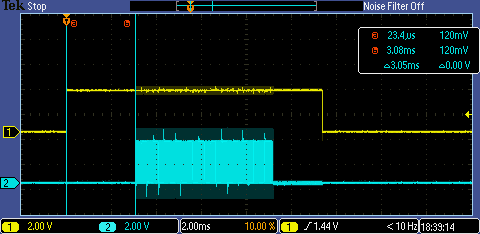
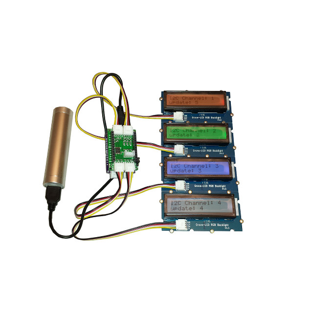
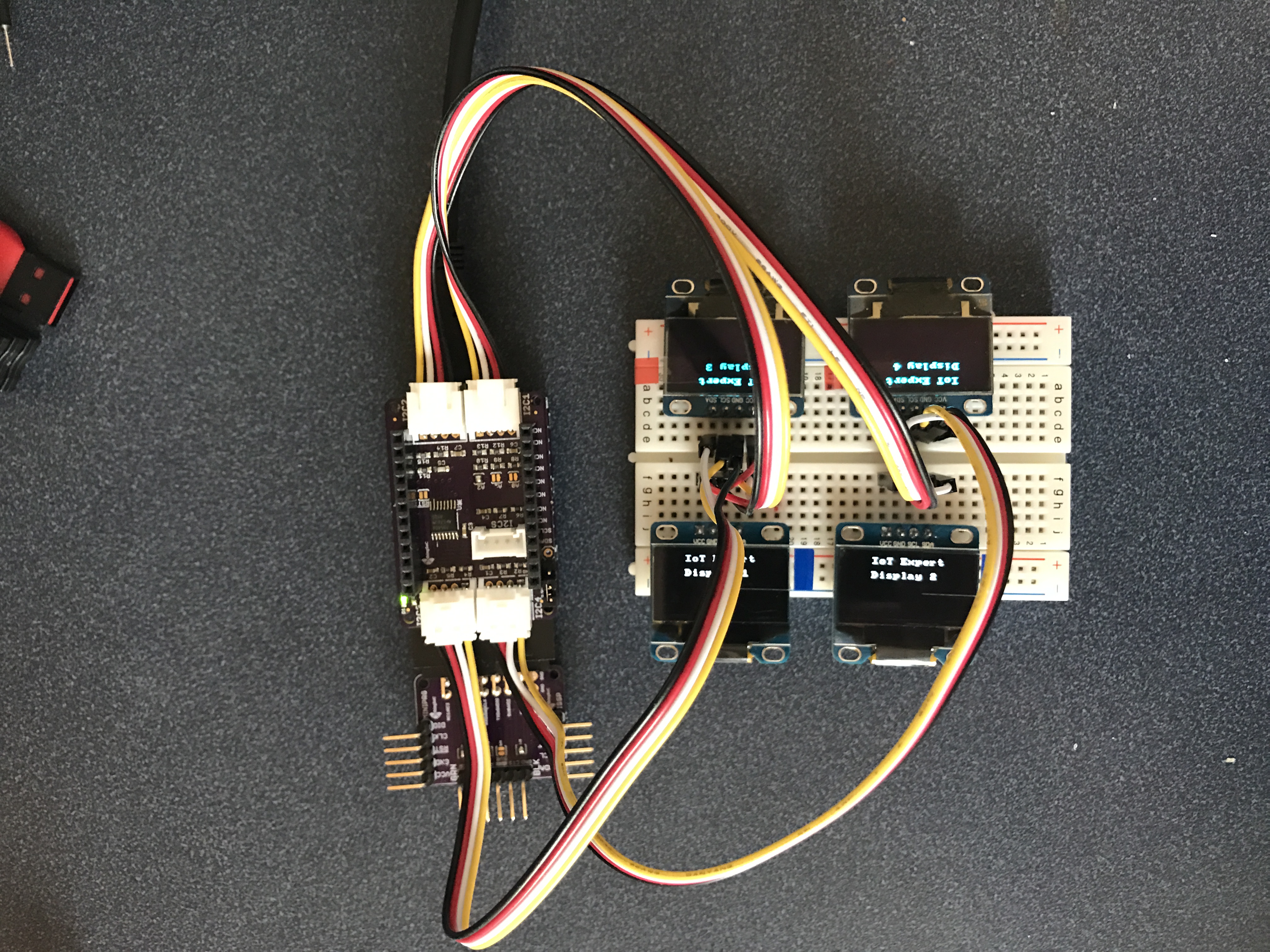
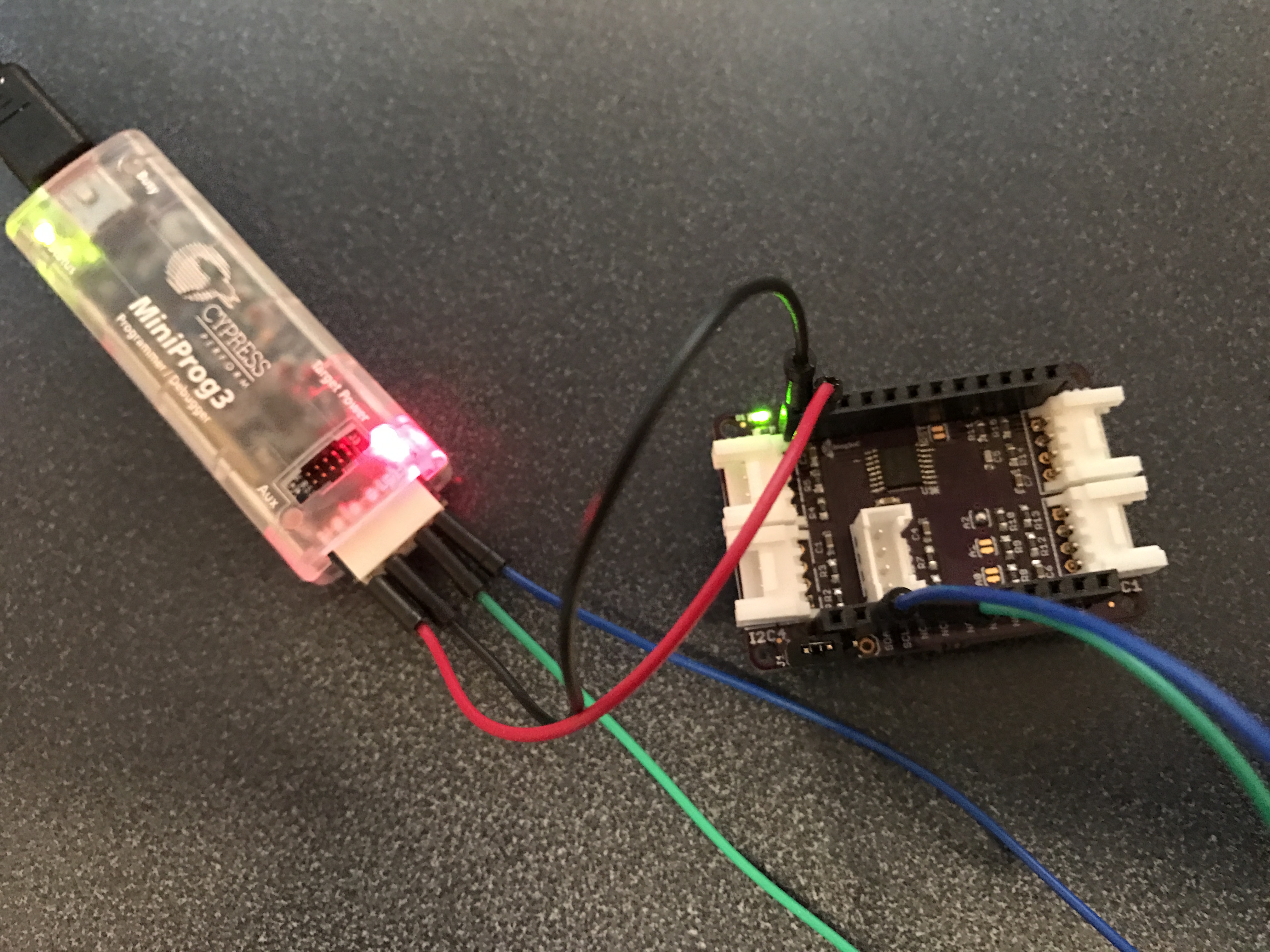
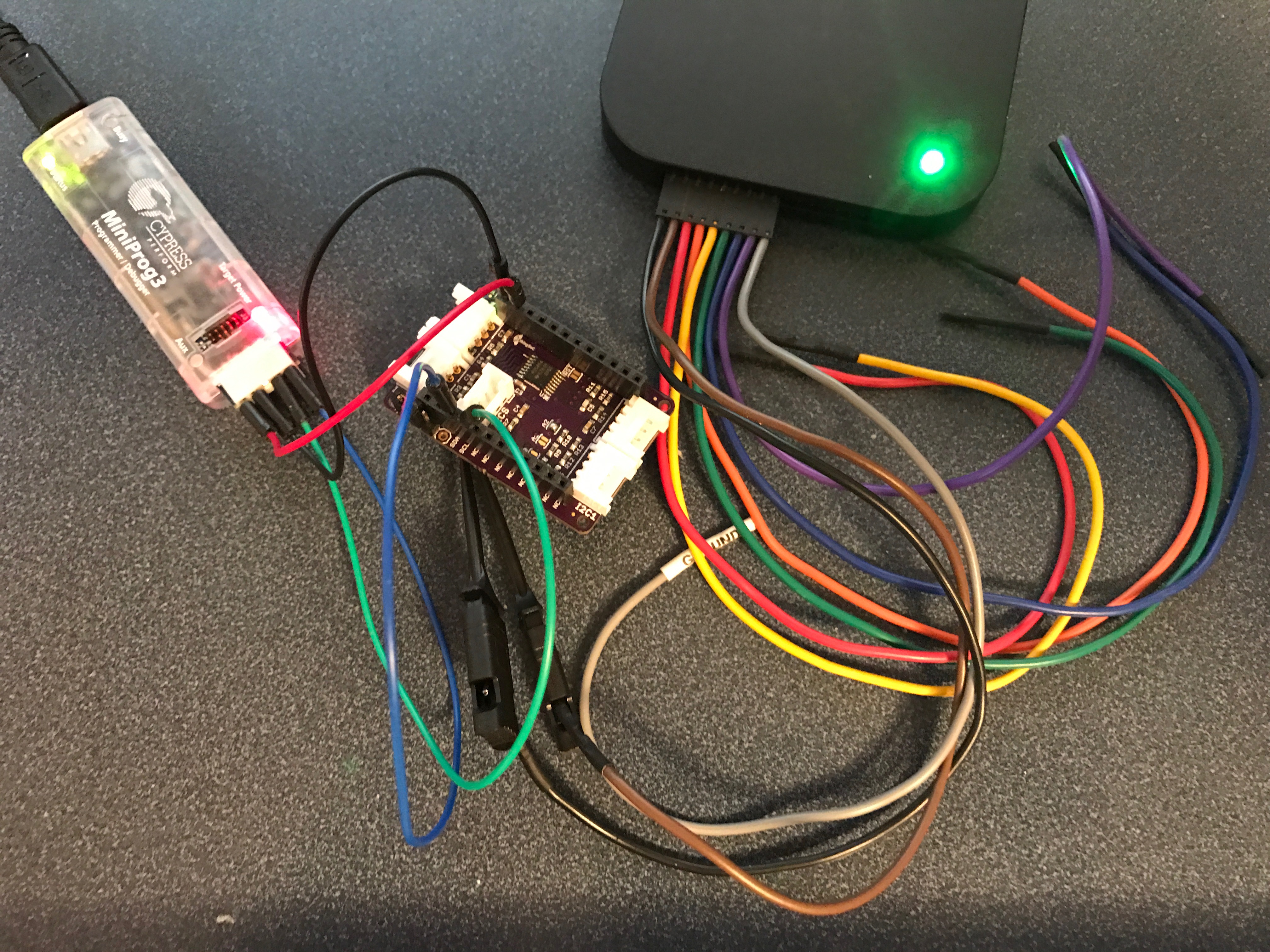
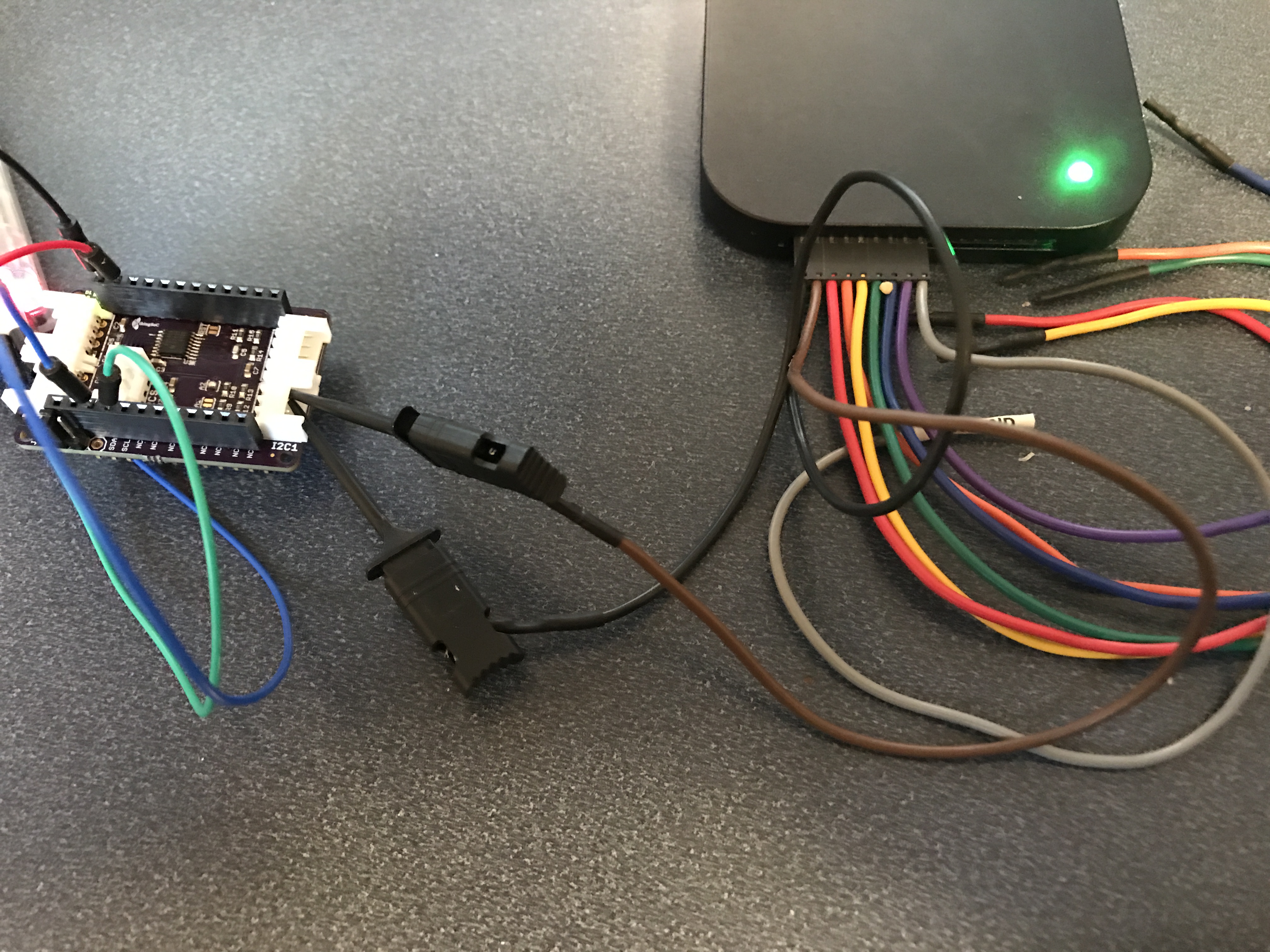
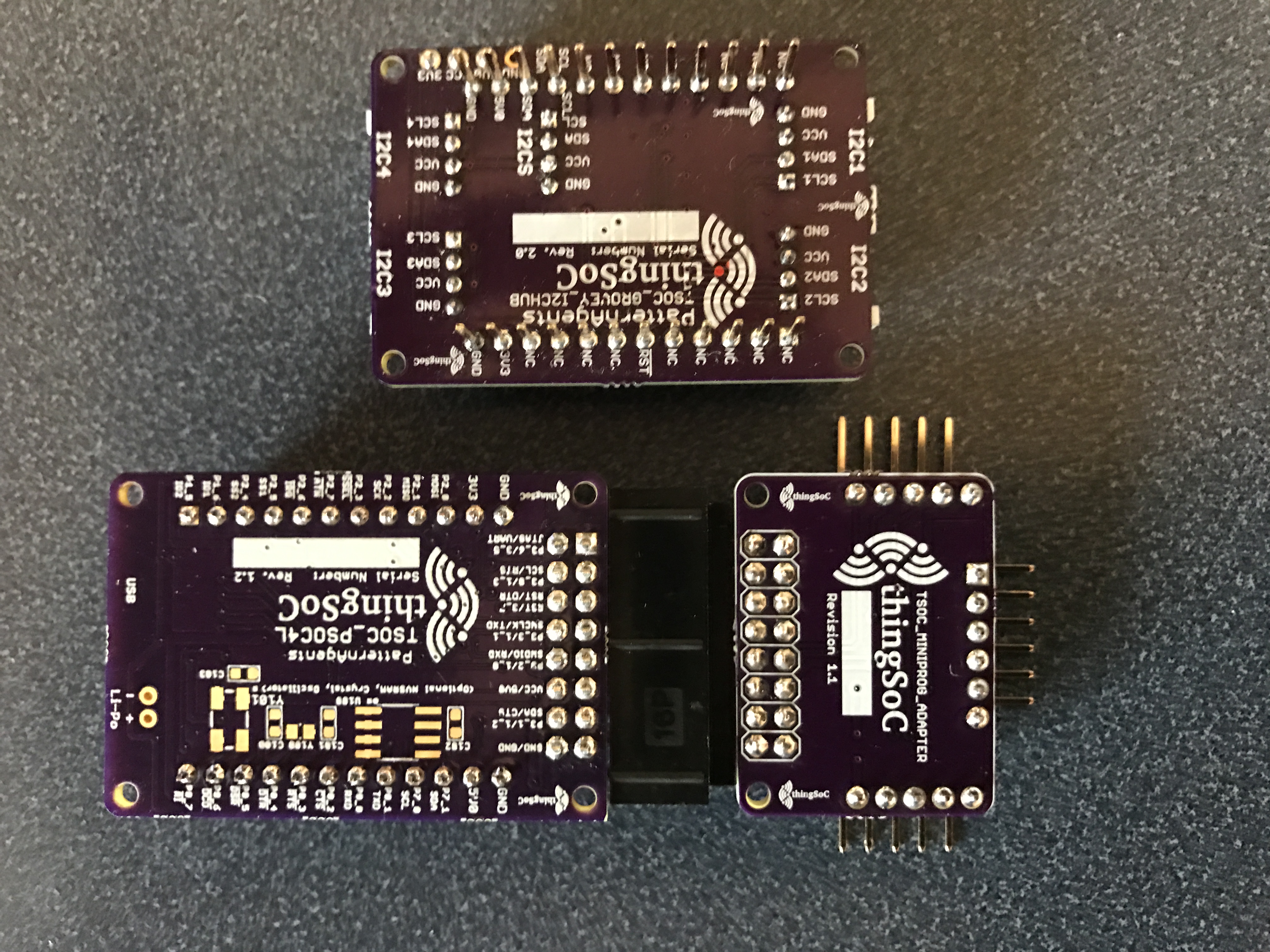
Here is a video I took on Saturday in my office with three different PSoCs (PSoC 4 BLE, PSoC 4M, and PSoC 6) running FreeRTOS. (yes my office looks like a tornado hit it). The moral of the story is never underestimate the power of the blinking LED (to figure out what is going on).
In this article I will show FreeRTOS PSoC Examples:
- Start with a single blinking LED Task
- Add 2nd UART based command processor thread
In the upcoming articles I will add more FreeRTOS PSoC Examples:
- Issue commands via a queue between the two threads
- Interrupt processing & a Semaphore
- Im not sure what else yet 🙂
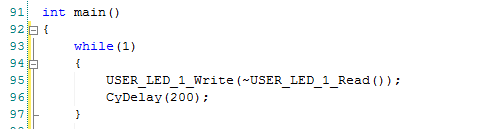
Single Blinking LED
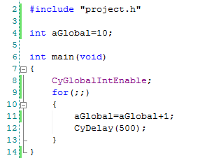
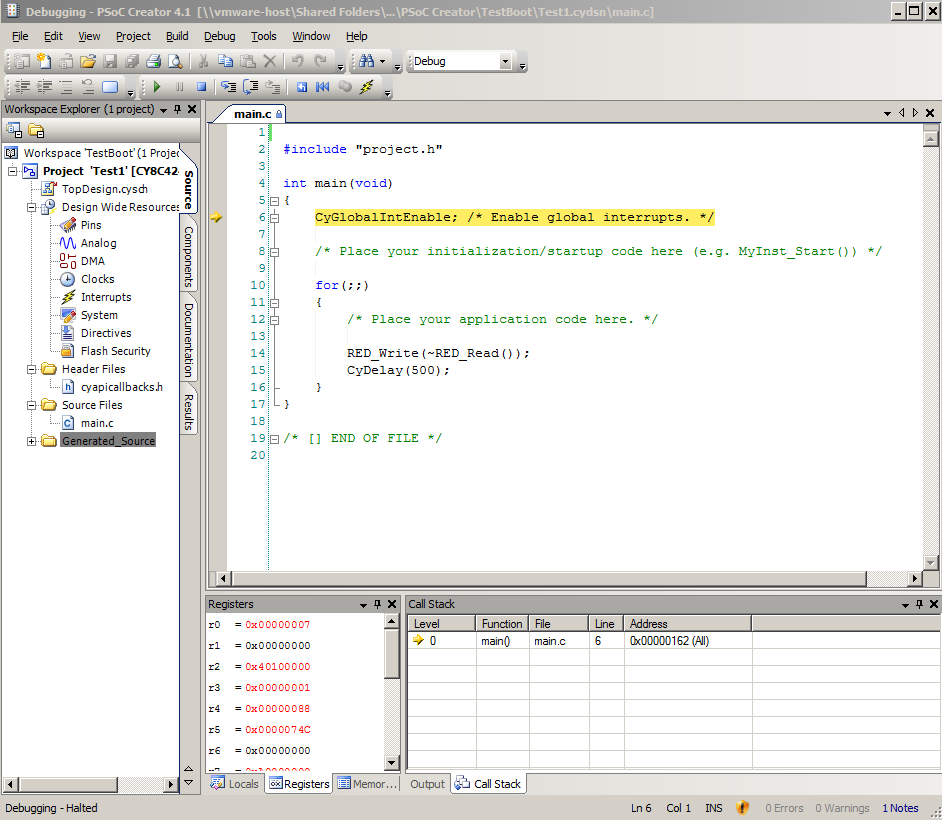
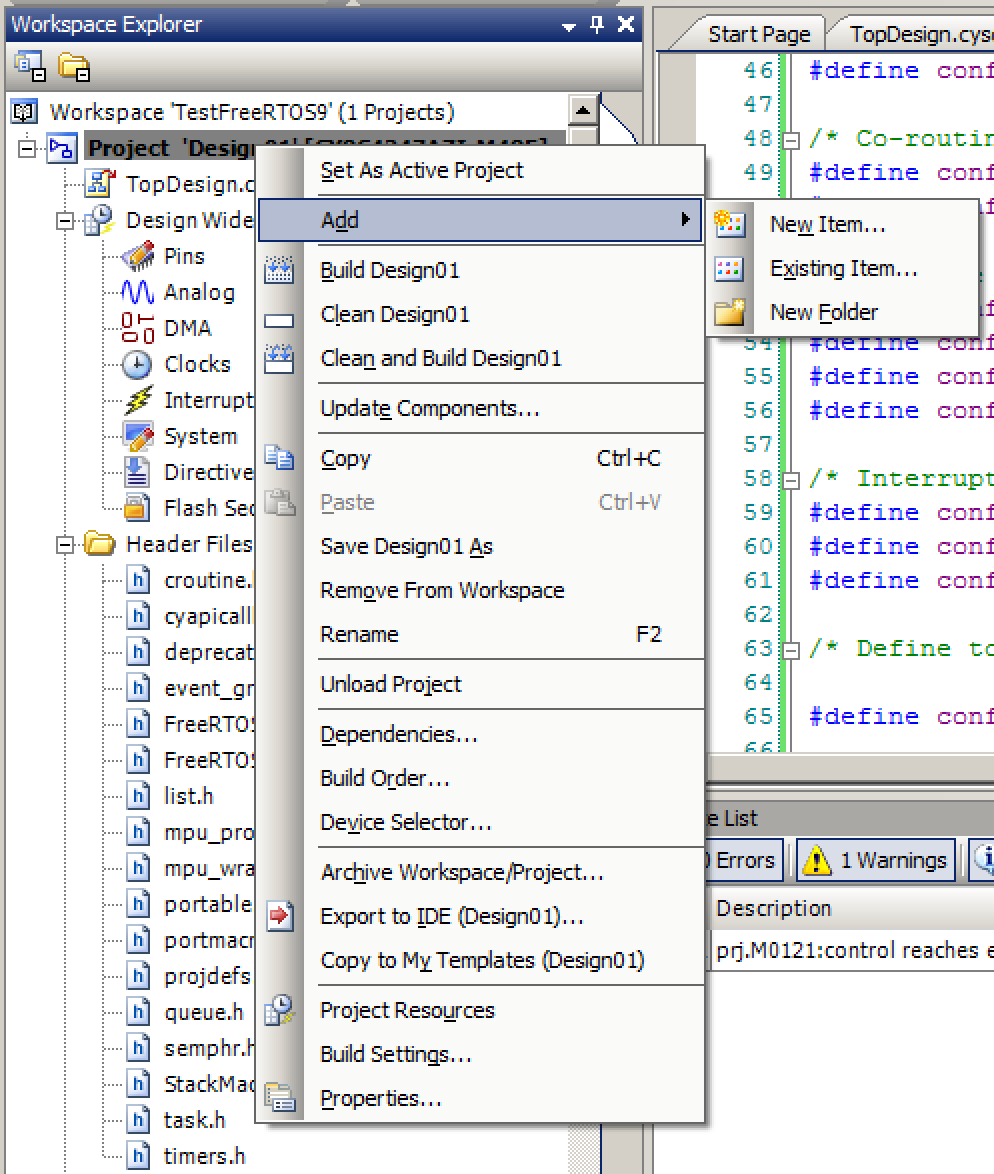
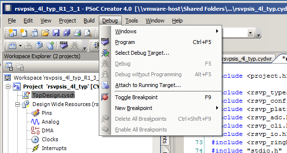
I start this process by following the instruction in my previous post to create a FreeRTOS example. The project is straight forward, it does:
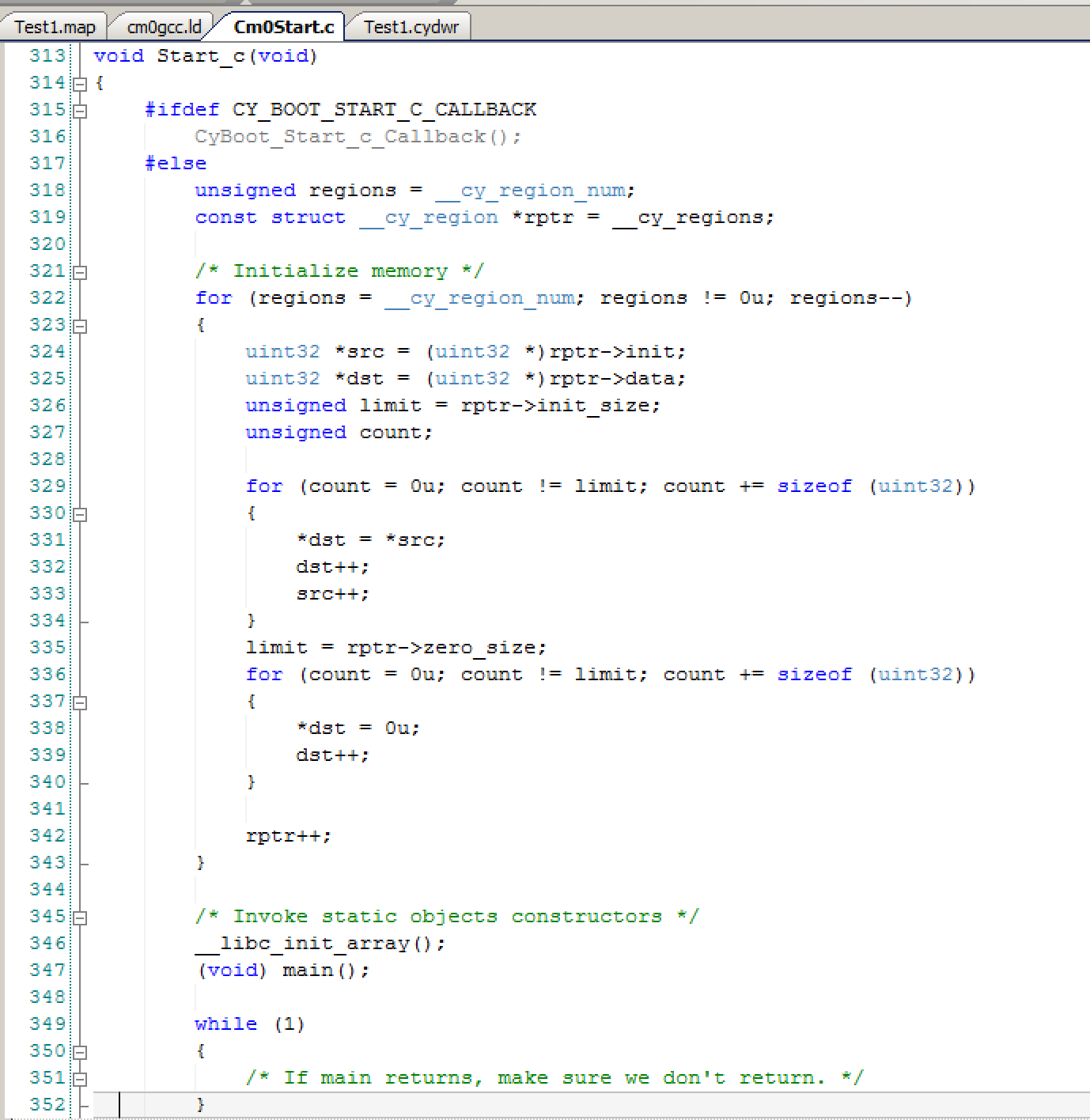
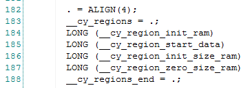
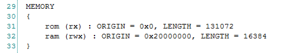
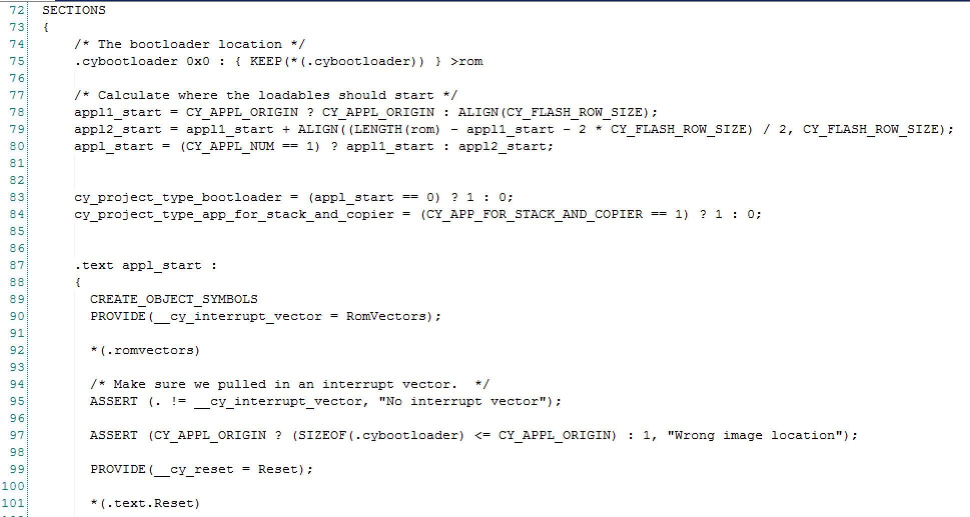
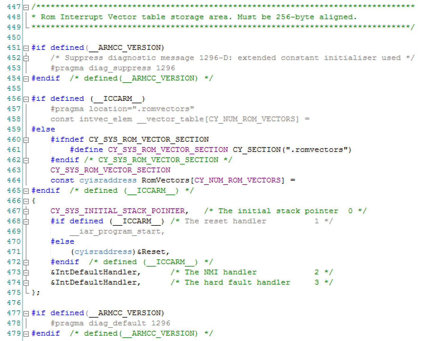
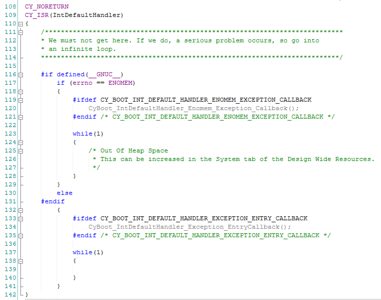
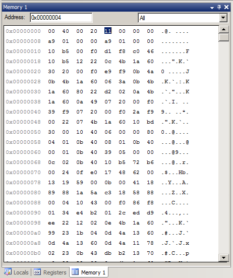
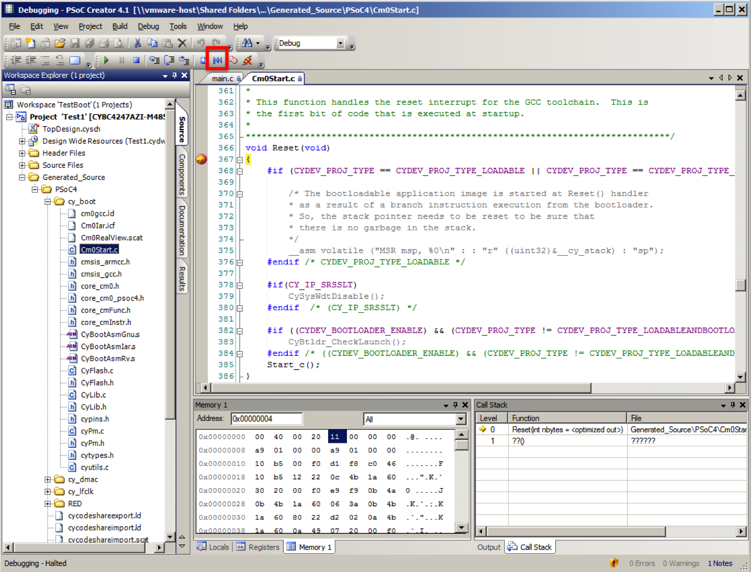
- Installs the FreeRTOS vectors (lines 9-22)
- Creates the LED Task (lines 41-48)
- Starts the scheduler (line 50)
- Runs the LED_Task until the end of time, blinking the LED (lines 25-33)
#include "project.h"
#include "FreeRTOS.h"
#include "timers.h"
extern void xPortPendSVHandler(void);
extern void xPortSysTickHandler(void);
extern void vPortSVCHandler(void);
#define CORTEX_INTERRUPT_BASE (16)
void setupFreeRTOS()
{
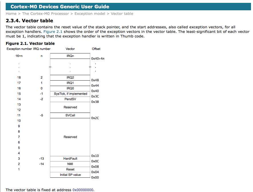
/* Handler for Cortex Supervisor Call (SVC, formerly SWI) - address 11 */
CyIntSetSysVector( CORTEX_INTERRUPT_BASE + SVCall_IRQn,
(cyisraddress)vPortSVCHandler );
/* Handler for Cortex PendSV Call - address 14 */
CyIntSetSysVector( CORTEX_INTERRUPT_BASE + PendSV_IRQn,
(cyisraddress)xPortPendSVHandler );
/* Handler for Cortex SYSTICK - address 15 */
CyIntSetSysVector( CORTEX_INTERRUPT_BASE + SysTick_IRQn,
(cyisraddress)xPortSysTickHandler );
}
void LED_Task(void *arg)
{
(void)arg;
while(1) {
RED_Write(~RED_Read());
vTaskDelay(500);
}
}
int main(void)
{
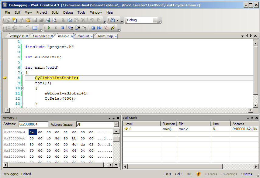
CyGlobalIntEnable; /* Enable global interrupts. */
setupFreeRTOS();
/* Create LED task, which will blink the LED */
xTaskCreate(
LED_Task, /* Task function */
"LED Blink", /* Task name (string) */
200, /* Task stack, allocated from heap */
0, /* No param passed to task function */
1, /* Low priority */
0 ); /* Not using the task handle */
vTaskStartScheduler();
while(1); // get rid of the stupid warning
}
You can see the blinking LED in the video from above.
UART Thread
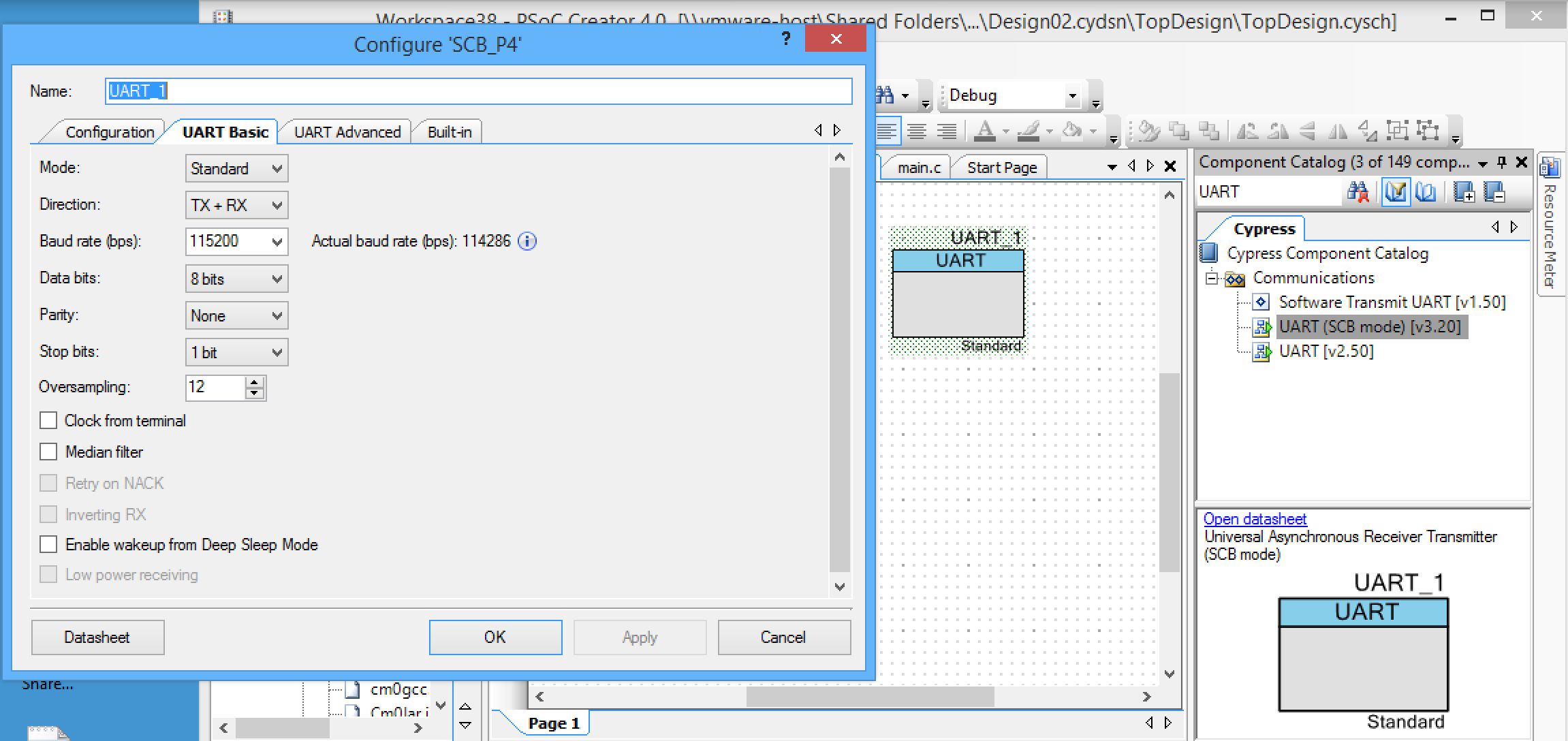
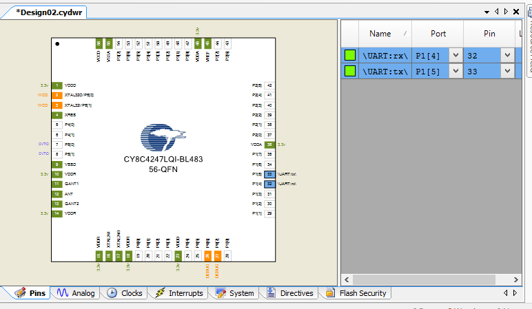
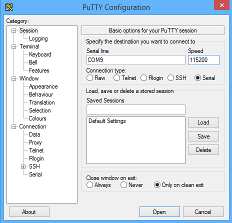
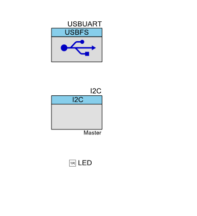
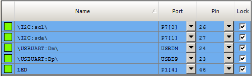
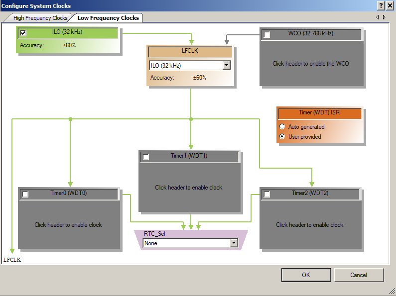
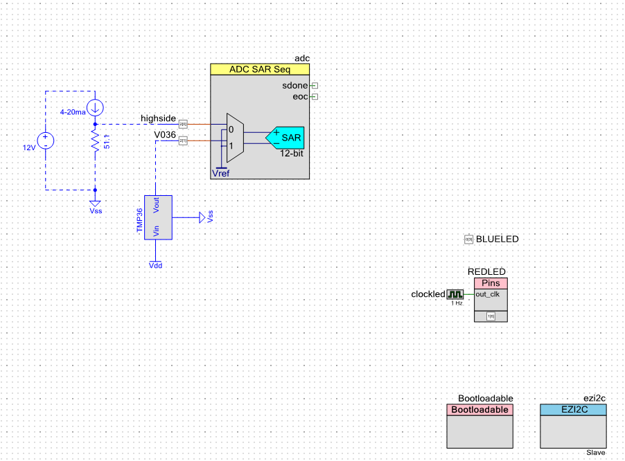
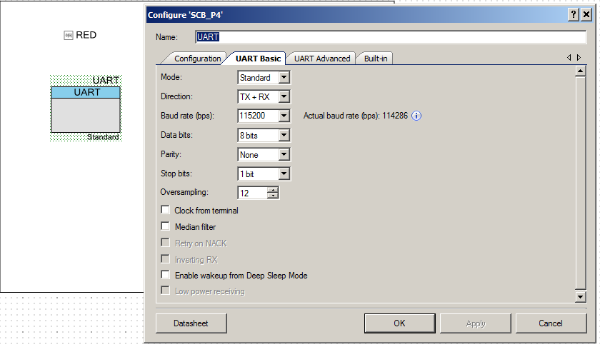
Once you have the blinking LED working, that means you have all of the environment setup etc… for some reason this always feels like a big step. I then copy the BlinkingLED project and give it the name “UART-Thread”. Then add a debugging UART to the schematic:
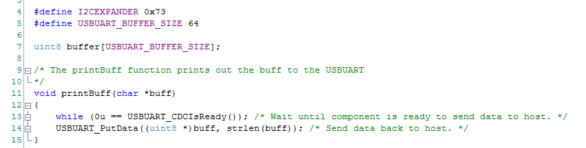
Now you can add the UART Thread to your project. It is pretty simple:
- Starts the UART
- Gets a key from the keyboard (line 47)
- If it is an ‘a’ it prints out “Working” (line 51)
- If it is a ‘t’ it calls the function vTaskList which makes a dump of the process currently running (more on this later) (lines 54-60)
#include "project.h"
#include "FreeRTOS.h"
#include "task.h"
#include "queue.h"
#include "event_groups.h"
#include "timers.h"
extern void xPortPendSVHandler(void);
extern void xPortSysTickHandler(void);
extern void vPortSVCHandler(void);
#define CORTEX_INTERRUPT_BASE (16)
void setupFreeRTOS()
{
/* Handler for Cortex Supervisor Call (SVC, formerly SWI) - address 11 */
CyIntSetSysVector( CORTEX_INTERRUPT_BASE + SVCall_IRQn,
(cyisraddress)vPortSVCHandler );
/* Handler for Cortex PendSV Call - address 14 */
CyIntSetSysVector( CORTEX_INTERRUPT_BASE + PendSV_IRQn,
(cyisraddress)xPortPendSVHandler );
/* Handler for Cortex SYSTICK - address 15 */
CyIntSetSysVector( CORTEX_INTERRUPT_BASE + SysTick_IRQn,
(cyisraddress)xPortSysTickHandler );
}
void LED_Task(void *arg)
{
(void)arg;
while(1) {
RED_Write(~RED_Read());
vTaskDelay(500);
}
}
void UART_Task(void *arg)
{
(void)arg;
static char buff[500];
UART_Start();
UART_UartPutString("Started UART\n\r");
char c;
while(1) {
c = UART_UartGetChar();
switch(c)
{
case 'a':
UART_UartPutString("Working\n\r");
break;
case 't':
UART_UartPutString("********************************************\n\r");
UART_UartPutString("Task State Prio Stack Num\n\r");
UART_UartPutString("********************************************\n\r");
vTaskList(buff);
UART_UartPutString(buff);
UART_UartPutString("*********************************************\n\r");
break;
}
taskYIELD();
}
}
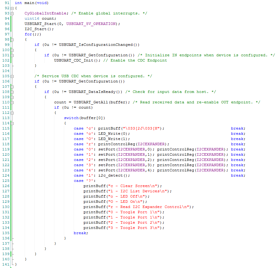
int main(void)
{
CyGlobalIntEnable; /* Enable global interrupts. */
setupFreeRTOS();
/* Create LED task, which will blink the LED */
xTaskCreate(
LED_Task, /* Task function */
"LED Blink", /* Task name (string) */
200, /* Task stack, allocated from heap */
0, /* No param passed to task function */
1, /* Low priority */
0 ); /* Not using the task handle */
/* Create UART Task which will control the serial port */
xTaskCreate(
UART_Task, /* Task function */
"UART", /* Task name (string) */
0x400, /* Task stack, allocated from heap */
0, /* No param passed to task function */
1, /* Low priority */
0 ); /* Not using the task handle */
vTaskStartScheduler();
while(1);
}
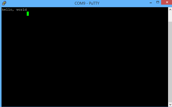
Testing the project
When I program the development kit, the LED starts blinking. That is good. Then I press ‘t’ which dumps out a table of the processes running. The columns are
- The name of the task
- The state of the task (R-Running, B-Blocked, S-Suspended)
- The priority (0-configMAX_PRIORITIES from FreeRTOSConfig.h)
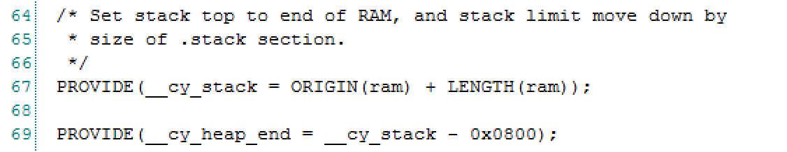
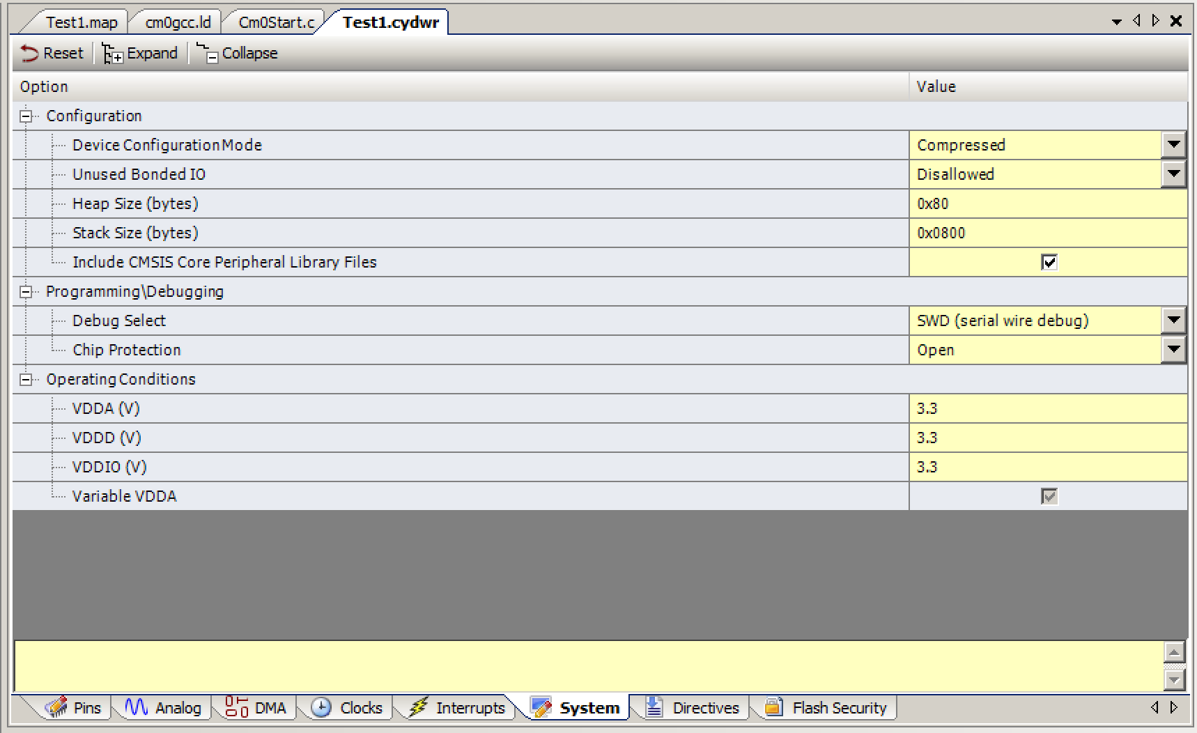
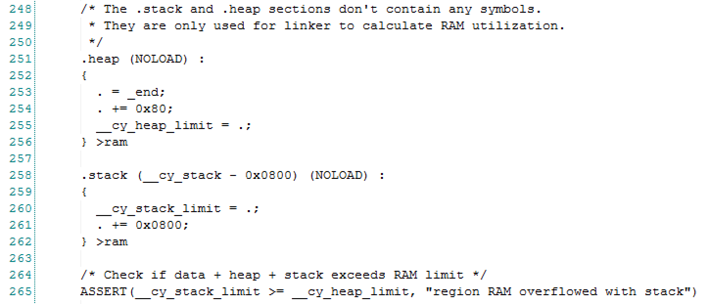
- The highwater mark of the stack usage of that thread. In the UART thread I declared 0x400 (1024) so it appears I have used most of the RAM.
- The task number
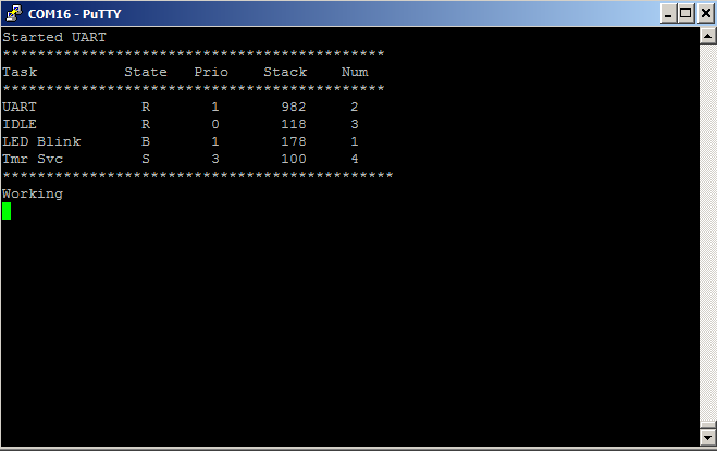
It is interesting that there are two tasks that I didnt create. The FreeRTOS requires that there alway be some task, so it automatically creates an IDLE tasks which it runs when there is nothing else available to run. It is possible to put the chip to sleep by adding to the IDLE task. The other task is the Timer Service task which is what enables me to use the software delay (vTaskDelay).
If you have more FreeRTOS PSoC Examples that you are interested in please make a comment and maybe Ill create them.
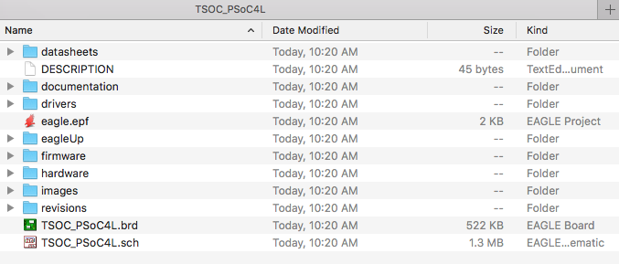
As always, you can find the FreeRTOS PSoC Examples on the IoT Expert GitHub site or git@github.com:iotexpert/PSoC-FreeRTOS-Examples.git
Topic
Description
FreeRTOS: A PSoC4 FreeRTOS Port
An introduction to making FreeRTOS work on PSoC 4
FreeRTOS PSoC Examples
Using multiple tasks in FreeRTOS
FreeRTOS Queue Example
Using a queue to communicate between tasks
PSoC 6 FreeRTOS - The First Example
Booting FreeRTOS on PSoC 6
FreeRTOS Binary Semaphore
An first example of a binary semaphore
FreeRTOS Binary Semaphore (Part 2)
Removing polling in the UART Task
FreeRTOS Counting Semaphore
An example using a counting semaphore
PSoC FreeRTOS
Reading I2C Sensors with a shared I2C Bus
PSoC FreeRTOS Task Notify
A light weight scheme to replace Semaphores
PSoC FreeRTOS Task Notification Values
A very light weight method to transfer one word of information into a task